EP4339010B1 - Vorrichtung zur übertragung elektrischer energie mit einem zentriersystem - Google Patents
Vorrichtung zur übertragung elektrischer energie mit einem zentriersystem Download PDFInfo
- Publication number
- EP4339010B1 EP4339010B1 EP23181030.0A EP23181030A EP4339010B1 EP 4339010 B1 EP4339010 B1 EP 4339010B1 EP 23181030 A EP23181030 A EP 23181030A EP 4339010 B1 EP4339010 B1 EP 4339010B1
- Authority
- EP
- European Patent Office
- Prior art keywords
- energy transfer
- lateral surface
- electrical
- housing
- electrical energy
- Prior art date
- Legal status (The legal status is an assumption and is not a legal conclusion. Google has not performed a legal analysis and makes no representation as to the accuracy of the status listed.)
- Active
Links
Images


Classifications
-
- H—ELECTRICITY
- H02—GENERATION; CONVERSION OR DISTRIBUTION OF ELECTRIC POWER
- H02J—CIRCUIT ARRANGEMENTS OR SYSTEMS FOR SUPPLYING OR DISTRIBUTING ELECTRIC POWER; SYSTEMS FOR STORING ELECTRIC ENERGY
- H02J50/00—Circuit arrangements or systems for wireless supply or distribution of electric power
- H02J50/90—Circuit arrangements or systems for wireless supply or distribution of electric power involving detection or optimisation of position, e.g. alignment
-
- B—PERFORMING OPERATIONS; TRANSPORTING
- B60—VEHICLES IN GENERAL
- B60L—PROPULSION OF ELECTRICALLY-PROPELLED VEHICLES; SUPPLYING ELECTRIC POWER FOR AUXILIARY EQUIPMENT OF ELECTRICALLY-PROPELLED VEHICLES; ELECTRODYNAMIC BRAKE SYSTEMS FOR VEHICLES IN GENERAL; MAGNETIC SUSPENSION OR LEVITATION FOR VEHICLES; MONITORING OPERATING VARIABLES OF ELECTRICALLY-PROPELLED VEHICLES; ELECTRIC SAFETY DEVICES FOR ELECTRICALLY-PROPELLED VEHICLES
- B60L53/00—Methods of charging batteries, specially adapted for electric vehicles; Charging stations or on-board charging equipment therefor; Exchange of energy storage elements in electric vehicles
- B60L53/30—Constructional details of charging stations
- B60L53/35—Means for automatic or assisted adjustment of the relative position of charging devices and vehicles
- B60L53/38—Means for automatic or assisted adjustment of the relative position of charging devices and vehicles specially adapted for charging by inductive energy transfer
-
- B—PERFORMING OPERATIONS; TRANSPORTING
- B60—VEHICLES IN GENERAL
- B60L—PROPULSION OF ELECTRICALLY-PROPELLED VEHICLES; SUPPLYING ELECTRIC POWER FOR AUXILIARY EQUIPMENT OF ELECTRICALLY-PROPELLED VEHICLES; ELECTRODYNAMIC BRAKE SYSTEMS FOR VEHICLES IN GENERAL; MAGNETIC SUSPENSION OR LEVITATION FOR VEHICLES; MONITORING OPERATING VARIABLES OF ELECTRICALLY-PROPELLED VEHICLES; ELECTRIC SAFETY DEVICES FOR ELECTRICALLY-PROPELLED VEHICLES
- B60L53/00—Methods of charging batteries, specially adapted for electric vehicles; Charging stations or on-board charging equipment therefor; Exchange of energy storage elements in electric vehicles
- B60L53/10—Methods of charging batteries, specially adapted for electric vehicles; Charging stations or on-board charging equipment therefor; Exchange of energy storage elements in electric vehicles characterised by the energy transfer between the charging station and the vehicle
- B60L53/12—Inductive energy transfer
-
- B—PERFORMING OPERATIONS; TRANSPORTING
- B60—VEHICLES IN GENERAL
- B60L—PROPULSION OF ELECTRICALLY-PROPELLED VEHICLES; SUPPLYING ELECTRIC POWER FOR AUXILIARY EQUIPMENT OF ELECTRICALLY-PROPELLED VEHICLES; ELECTRODYNAMIC BRAKE SYSTEMS FOR VEHICLES IN GENERAL; MAGNETIC SUSPENSION OR LEVITATION FOR VEHICLES; MONITORING OPERATING VARIABLES OF ELECTRICALLY-PROPELLED VEHICLES; ELECTRIC SAFETY DEVICES FOR ELECTRICALLY-PROPELLED VEHICLES
- B60L53/00—Methods of charging batteries, specially adapted for electric vehicles; Charging stations or on-board charging equipment therefor; Exchange of energy storage elements in electric vehicles
- B60L53/30—Constructional details of charging stations
- B60L53/302—Cooling of charging equipment
-
- B—PERFORMING OPERATIONS; TRANSPORTING
- B60—VEHICLES IN GENERAL
- B60L—PROPULSION OF ELECTRICALLY-PROPELLED VEHICLES; SUPPLYING ELECTRIC POWER FOR AUXILIARY EQUIPMENT OF ELECTRICALLY-PROPELLED VEHICLES; ELECTRODYNAMIC BRAKE SYSTEMS FOR VEHICLES IN GENERAL; MAGNETIC SUSPENSION OR LEVITATION FOR VEHICLES; MONITORING OPERATING VARIABLES OF ELECTRICALLY-PROPELLED VEHICLES; ELECTRIC SAFETY DEVICES FOR ELECTRICALLY-PROPELLED VEHICLES
- B60L53/00—Methods of charging batteries, specially adapted for electric vehicles; Charging stations or on-board charging equipment therefor; Exchange of energy storage elements in electric vehicles
- B60L53/30—Constructional details of charging stations
- B60L53/34—Plug-like or socket-like devices specially adapted for contactless inductive charging of electric vehicles
-
- B—PERFORMING OPERATIONS; TRANSPORTING
- B60—VEHICLES IN GENERAL
- B60L—PROPULSION OF ELECTRICALLY-PROPELLED VEHICLES; SUPPLYING ELECTRIC POWER FOR AUXILIARY EQUIPMENT OF ELECTRICALLY-PROPELLED VEHICLES; ELECTRODYNAMIC BRAKE SYSTEMS FOR VEHICLES IN GENERAL; MAGNETIC SUSPENSION OR LEVITATION FOR VEHICLES; MONITORING OPERATING VARIABLES OF ELECTRICALLY-PROPELLED VEHICLES; ELECTRIC SAFETY DEVICES FOR ELECTRICALLY-PROPELLED VEHICLES
- B60L53/00—Methods of charging batteries, specially adapted for electric vehicles; Charging stations or on-board charging equipment therefor; Exchange of energy storage elements in electric vehicles
- B60L53/30—Constructional details of charging stations
- B60L53/35—Means for automatic or assisted adjustment of the relative position of charging devices and vehicles
-
- H—ELECTRICITY
- H01—ELECTRIC ELEMENTS
- H01F—MAGNETS; INDUCTANCES; TRANSFORMERS; SELECTION OF MATERIALS FOR THEIR MAGNETIC PROPERTIES
- H01F38/00—Adaptations of transformers or inductances for specific applications or functions
- H01F38/14—Inductive couplings
-
- H—ELECTRICITY
- H02—GENERATION; CONVERSION OR DISTRIBUTION OF ELECTRIC POWER
- H02J—CIRCUIT ARRANGEMENTS OR SYSTEMS FOR SUPPLYING OR DISTRIBUTING ELECTRIC POWER; SYSTEMS FOR STORING ELECTRIC ENERGY
- H02J50/00—Circuit arrangements or systems for wireless supply or distribution of electric power
- H02J50/005—Mechanical details of housing or structure aiming to accommodate the power transfer means, e.g. mechanical integration of coils, antennas or transducers into emitting or receiving devices
-
- H—ELECTRICITY
- H02—GENERATION; CONVERSION OR DISTRIBUTION OF ELECTRIC POWER
- H02J—CIRCUIT ARRANGEMENTS OR SYSTEMS FOR SUPPLYING OR DISTRIBUTING ELECTRIC POWER; SYSTEMS FOR STORING ELECTRIC ENERGY
- H02J50/00—Circuit arrangements or systems for wireless supply or distribution of electric power
- H02J50/10—Circuit arrangements or systems for wireless supply or distribution of electric power using inductive coupling
-
- H02J7/70—
-
- B—PERFORMING OPERATIONS; TRANSPORTING
- B60—VEHICLES IN GENERAL
- B60L—PROPULSION OF ELECTRICALLY-PROPELLED VEHICLES; SUPPLYING ELECTRIC POWER FOR AUXILIARY EQUIPMENT OF ELECTRICALLY-PROPELLED VEHICLES; ELECTRODYNAMIC BRAKE SYSTEMS FOR VEHICLES IN GENERAL; MAGNETIC SUSPENSION OR LEVITATION FOR VEHICLES; MONITORING OPERATING VARIABLES OF ELECTRICALLY-PROPELLED VEHICLES; ELECTRIC SAFETY DEVICES FOR ELECTRICALLY-PROPELLED VEHICLES
- B60L2200/00—Type of vehicles
- B60L2200/10—Air crafts
-
- H—ELECTRICITY
- H02—GENERATION; CONVERSION OR DISTRIBUTION OF ELECTRIC POWER
- H02J—CIRCUIT ARRANGEMENTS OR SYSTEMS FOR SUPPLYING OR DISTRIBUTING ELECTRIC POWER; SYSTEMS FOR STORING ELECTRIC ENERGY
- H02J7/00—Circuit arrangements for charging or depolarising batteries or for supplying loads from batteries
- H02J7/02—Circuit arrangements for charging or depolarising batteries or for supplying loads from batteries for charging batteries from AC mains by converters
Definitions
- the present application relates to an electrical energy transfer device comprising a centering system. This device is intended to equip a flying vehicle and a ground module.
- a contactless electrical energy transfer device comprises an electrical energy transmitter system 10 and an electrical energy receiver system 12, the transmitter and receiver systems being movable relative to each other and configured to allow a transfer of electrical energy by magnetic induction when they are in a close state, close to each other.
- first and second coils 16, 24 each have a double-D shape and the first and second housings 14, 22 are filled with a filling resin.
- the first and second portions are necessarily positioned so as to ensure optimum electrical energy transfer by virtue of the housing which allows the first and second electrical energy transfer elements to be centered relative to each other.
- At least one of the first and second portions comprises a guidance sensor to assist in positioning the first and second portions relative to each other in a centered manner.
- the first part comprises at least one cooling system configured to maintain the layer of ferromagnetic elements at a temperature below a given threshold.
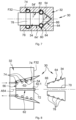
- the transfer of electrical energy can be used to recharge at least one electrical energy storage system present in the flying vehicle 38 and/or to power at least one electrical equipment present in the flying vehicle 38.
- the ground module 36 is static. According to other applications visible on the Figures 9 and 10 , the ground module 36 is mobile and corresponds to a land vehicle. According to a configuration visible on the figure 9 , the ground module 36, mobile, is connected by an electric cable 36.1 to an electric power supply 40 to power the first part 32 of the electric energy transfer device 30. According to another configuration visible on the figure 10 , the ground module 36, mobile, comprises at least one rechargeable electrical energy storage system 36.2 for powering the first part 32 of the electrical energy transfer device 30.
- the electrical energy transfer device 30 comprises a contactless electrical energy transfer system between a first electrical circuit C32 secured to the first part 32 and a second electrical circuit C34 secured to the second part 34.
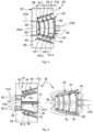
- the contactless energy transfer system comprises at least a first coil 42 secured to the first part 32 and connected to the first electrical circuit C32 as well as a second coil 44 secured to the second part 34 and connected to the second electrical circuit C34.
- the first part 32 comprises, in addition to the first coil 42, a first front face F32 substantially perpendicular to the direction of approach, at least one layer of ferromagnetic elements 46, made of ferrite for example, as well as a first support 48 supporting the first coil 42 and the layer of ferromagnetic elements 46.
- the first part 32 can comprise at least one shielding plate.
- this first axis of revolution A54 is perpendicular to the first frontal face F32 of the first part 32.
- the first support 48 is a block of material, for example resin, which has a first surface corresponding to the first front face F32 as well as a hollow corresponding to the first housing 52.
- the turns of the first coil 42 or the first coils 42 are completely embedded in the block of material of the first support 48 and offset towards the inside of the first support 48 relative to the first lateral surface 54 while being slightly spaced from said first lateral surface 54.
- the turns of the first coil 42 or the first coils 42 are partially embedded in the block of material of the first support 48 and positioned astride the first lateral surface 54.
- the turns of the first coil 42 or the first coils 42 are not embedded in the block of material of the first support 48 and offset towards the outside of the first support 48 relative to the first lateral surface 54 while being slightly spaced from said first lateral surface 54.
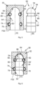
- the first part 32 comprises at least one centering pin 62, oriented parallel to the approach direction, which has a first end connected to the first part 32 as well as a second free end 62.1.
- the centering pin 62 is cylindrical and its free end 62.1 is positioned approximately in the same plane as the first front face F32 of the first part 32.
- the cylindrical centering pin 62 has an axis coincident with the first axis of revolution A54.
- At least one ferromagnetic element 63 is positioned in the centering pin 62.
- the second part 34 has at least one second lateral surface 64 substantially identical to a homothety near the first surface 54 of the first housing 52 of the first part 32.
- the second lateral surface 64 has at least one second axis of revolution A64 and a second lateral surface 64 for each first lateral surface 54 of the housing 52 of the first part 32, each second lateral surface 64 being substantially identical to a homothety near the corresponding first lateral surface 54.
- the second part 34 has a general shape complementary to the shape of the first housing 52.
- the second part 34 comprises several second coils 44 wound at the second lateral surface 64, offset from each other in the direction of approach.
- the second coils 44 are regularly distributed in the direction of approach.
- the second support 50 is a block of material, for example made of resin, which has a first surface corresponding to the second front face 66 as well as a lateral face corresponding to the second lateral surface 64.
- the turns of the second coil 44 or the second coils 44 are held stationary relative to the first part 34 by any suitable holding system.
- the second part 34 comprises a second housing 70 for each centering pin 62, configured to house the latter in a fitted manner.
- This second housing 70 comprises a cylindrical side wall having a diameter substantially identical to that of the centering pin 62. According to one arrangement, the second housing 70 has an axis coincident with the second axis of revolution A64.
- At least one of the first and second portions 32, 34 comprises a guidance sensor 72 for assisting in positioning the first and second portions 32, 34 relative to each other in a centered manner.
- the guidance sensor 72 is a positioning sensor.
- the guidance sensor 72 is positioned at the second free end 62.1 of the centering pin 62 of the first portion 32.
- the second part 34 is at least partially housed in the first housing 52 of the first part 32 and the first and second coils 42, 44 are positioned opposite each other, the second coils 44 being positioned inside the first coils 44 in a centered manner.
- Providing a housing 52 with cross sections which decrease from the first front face F32 of the first part 32 allows, when introducing the second part 34 into the housing 52, self-centering to be achieved.
- the electrical energy transfer device 30 comprises at least one electrical energy transfer system with contact configured to ensure a transfer of electrical energy between a first electrical circuit C32 secured to the first part 32 and a second electrical circuit C34 secured to the second part 34.
- the first lateral surface 54 comprises at least one portion of a surface of revolution having a first axis of revolution A54.
- the first lateral surface 54 or only a portion of the first lateral surface 54 is a surface of revolution and has a first axis of revolution A54.
- this first axis of revolution A54 is perpendicular to the first frontal face F32 of the first part 32.
- the first housing 52 may comprise a bottom 56 substantially perpendicular to the axis of revolution A54.
- the first housing 52 or the first lateral surface 54 has cross-sections (in planes perpendicular to the first axis of revolution A54) which decrease as they move away from the first front face F32. This configuration makes it possible to obtain self-centering when inserting the second part 34 into the first housing 52 of the first part 32.
- the housing 52 comprises two first lateral surfaces 54, 54', a first distal lateral surface 54, spaced from the first front face F32, having cross sections which decrease as they move away from the first front face F32 as well as a first emerging lateral surface 54', adjacent to the first front face F32, positioned between the first distal lateral surface 54 and the first front face F32, having constant cross sections.
- the first distal lateral surface 54 is semi-spherical and the first emerging lateral surface 54' is cylindrical.
- the first distal lateral surface 54 is conical and the first emerging lateral surface 54' is cylindrical.
- the housing 52 comprises a single first lateral surface 54, for example frustoconical.
- the electrical energy transfer system with contact comprises at least one torus-shaped helical spring 74 and connected to the first or second electrical circuit C32, C34 which, when the first and second parts 32, 34 are in the close state as illustrated in the figure 6 , is interposed between the first and second lateral surfaces 54, 64 of the first and second parts 32, 34 and ensures electrical continuity between the first and second electrical circuits C32, C34 of the first and second parts 32, 34.
- At least one of the first and second portions 32, 34 comprises a peripheral groove 76, positioned at a first or second lateral surface 54, 64, configured to partially accommodate the torus-shaped coil spring 74 such that the latter projects relative to the first or second lateral surface 54, 64.
- the peripheral groove 76 is provided on the first part 32.
- the electrical energy transfer system with contact comprises a contact terminal 78 connected to a first or second electrical circuit C32, C34 different from that to which the torus-shaped helical spring 74 is connected.
- the latter and the contact terminal 78 are arranged such that the torus-shaped helical spring 74 is in contact with the contact terminal 78 when the first and second parts 32, 34 are in the close state.
Landscapes
- Engineering & Computer Science (AREA)
- Power Engineering (AREA)
- Transportation (AREA)
- Mechanical Engineering (AREA)
- Computer Networks & Wireless Communication (AREA)
- Charge And Discharge Circuits For Batteries Or The Like (AREA)
- Current-Collector Devices For Electrically Propelled Vehicles (AREA)
- Transmission Devices (AREA)
- Battery Mounting, Suspending (AREA)
Claims (6)
- Vorrichtung zur Übertragung elektrischer Energie durch magnetische Induktion, beinhaltend einen ersten Teil (32), der eine erste Stirnfläche (F32) und mindestens ein erstes Element zur Übertragung elektrischer Energie umfasst, sowie einen zweiten Teil (34), der mindestens ein zweites Element zur Übertragung elektrischer Energie umfasst, wobei der erste und der zweite Teil (32, 34) entlang einer Annäherungsrichtung zwischen einem beabstandeten Zustand und einem angenäherten Zustand relativ zueinander beweglich sind, wobei das erste und das zweite Element zur Übertragung elektrischer Energie dazu konfiguriert sind, im angenäherten Zustand eine Übertragung elektrischer Energie zwischen sich zu gewährleisten; wobei der erste Teil (32) eine erste Aufnahme (52) beinhaltet, die an der ersten Stirnfläche (F32) des ersten Teils (32) mündet und mindestens eine erste Seitenoberfläche (54) umfasst, wobei die erste Aufnahme (52) dazu konfiguriert ist, den zweiten Teil (34) mindestens teilweise aufzunehmen, wobei der zweite Teil (34) für jede erste Seitenoberfläche (54) der ersten Aufnahme (52) des ersten Teils (32) eine zweite Seitenoberfläche (64) aufweist, wobei der zweite Teil (34) eine zu der Form der ersten Aufnahme (52) komplementäre allgemeine Form aufweist, wobei jedes erste Element zur Übertragung elektrischer Energie an der ersten Seitenoberfläche (54) positioniert ist und jedes zweite Element zur Übertragung elektrischer Energie an der zweiten Seitenoberfläche (64) und relativ zu einem der ersten Elemente zur Übertragung elektrischer Energie ungefähr zentriert positioniert ist, wenn sich der erste und der zweite Teil (32, 34) im angenäherten Zustand befinden, wobei der erste Teil (32) ferner mindestens eine Schicht ferromagnetischer Elemente (46) beinhaltet, die die erste Seitenoberfläche (54) umgibt, wobei jedes erste Element zur Übertragung elektrischer Energie zwischen der Schicht ferromagnetischer Elemente (46) und der ersten Oberfläche (54) positioniert ist, dadurch gekennzeichnet, dass mindestens eine erste Seitenoberfläche (54) Querschnitte aufweist, die mit zunehmenden Abstand von der ersten Stirnfläche (F32) abnehmen, dass die Schicht ferromagnetischer Elemente (46) eine Geometrie aufweist, die zu der ersten Seitenoberfläche (54) bis auf eine Homothetie im Wesentlichen identisch ist, dass der erste Teil (32) mindestens einen Zentrierstift (62) in der ersten Aufnahme (52) beinhaltet, der zu der Annäherungsrichtung parallel ausgerichtet ist, dass der zweite Teil (34) mindestens eine zweite Aufnahme (70) beinhaltet, die dazu konfiguriert ist, den mindestens einen Zentrierstift (62) aufzunehmen, und dass der erste Teil (32) ein ferromagnetisches Element (63) beinhaltet, das in dem Zentrierstift (62) positioniert ist.
- Vorrichtung zur Übertragung elektrischer Energie nach dem vorhergehenden Anspruch, dadurch gekennzeichnet, dass die Vorrichtung mehrere erste oder zweite Elemente zur Übertragung elektrischer Energie beinhaltet, die entlang der Annäherungsrichtung relativ zueinander versetzt sind.
- Vorrichtung zur Übertragung elektrischer Energie nach einem der vorhergehenden Ansprüche, dadurch gekennzeichnet, dass jede erste Seitenoberfläche (54) eine rotationssymmetrische Oberfläche ist.
- Vorrichtung zur Übertragung elektrischer Energie nach einem der vorhergehenden Ansprüche, dadurch gekennzeichnet, dass die erste Aufnahme (52) zwei erste Seitenoberflächen (54, 54') beinhaltet, darunter eine erste distale Seitenoberfläche (54), die von der ersten Stirnfläche (F32) beabstandet ist und Querschnitte aufweist, die mit zunehmendem Abstand von der ersten Stirnfläche (F32) abnehmen, sowie eine erste mündende Seitenoberfläche (54'), die an die erste Stirnfläche (F32) angrenzt, zwischen der ersten distalen Seitenoberfläche (54) und der ersten Stirnfläche (F32) positioniert ist und konstante Querschnitte aufweist.
- Vorrichtung zur Übertragung elektrischer Energie nach einem der vorhergehenden Ansprüche, dadurch gekennzeichnet, dass mindestens einer der Teile von dem ersten und dem zweiten Teil (32, 34) einen Führungssensor (72) beinhaltet, um dabei zu helfen, den ersten und den zweiten Teil (32, 34) auf zentrierte Weise relativ zueinander zu positionieren.
- Vorrichtung zur Übertragung elektrischer Energie nach einem der vorhergehenden Ansprüche, dadurch gekennzeichnet, dass jedes erste Element zur Übertragung elektrischer Energie eine erste Spule (42) oder eine Windung (42.1, 42.2) einer ersten Spule (42) ist und dass jedes zweite Element zur Übertragung elektrischer Energie eine zweite Spule (48) oder eine Windung (44.1, 44.2) einer zweiten Spule (42) ist.
Applications Claiming Priority (1)
| Application Number | Priority Date | Filing Date | Title |
|---|---|---|---|
| FR2208460 | 2022-08-23 |
Publications (3)
| Publication Number | Publication Date |
|---|---|
| EP4339010A2 EP4339010A2 (de) | 2024-03-20 |
| EP4339010A3 EP4339010A3 (de) | 2024-05-22 |
| EP4339010B1 true EP4339010B1 (de) | 2025-01-01 |
Family
ID=83506560
Family Applications (1)
| Application Number | Title | Priority Date | Filing Date |
|---|---|---|---|
| EP23181030.0A Active EP4339010B1 (de) | 2022-08-23 | 2023-06-22 | Vorrichtung zur übertragung elektrischer energie mit einem zentriersystem |
Country Status (3)
| Country | Link |
|---|---|
| US (1) | US12214687B2 (de) |
| EP (1) | EP4339010B1 (de) |
| CN (1) | CN117639300A (de) |
Family Cites Families (9)
| Publication number | Priority date | Publication date | Assignee | Title |
|---|---|---|---|---|
| JP2000114079A (ja) * | 1998-10-01 | 2000-04-21 | Harness Syst Tech Res Ltd | 電磁誘導型コネクタ |
| DE10055090A1 (de) * | 2000-11-07 | 2002-05-08 | Conducta Endress & Hauser | Steckverbinder zum Anschluss einer Übertragungsleitung an mindestens einen Sensor |
| JP3864094B2 (ja) * | 2002-01-10 | 2006-12-27 | Fdk株式会社 | 非接触給電カプラ |
| EP2581993B1 (de) * | 2011-10-13 | 2014-06-11 | TE Connectivity Nederland B.V. | Kontaktlose Steckdose und kontaktloses Steckdosensystem |
| JP5852873B2 (ja) * | 2011-12-16 | 2016-02-03 | Udトラックス株式会社 | 非接触給電システム |
| US8971072B2 (en) * | 2011-12-30 | 2015-03-03 | Bedrock Automation Platforms Inc. | Electromagnetic connector for an industrial control system |
| EP2770645B1 (de) * | 2013-02-21 | 2018-01-31 | Nxp B.V. | Nichtgalavnischer Verbinder |
| JP2019045163A (ja) * | 2017-08-30 | 2019-03-22 | 日立Geニュークリア・エナジー株式会社 | 無人移動体を用いた構造体点検システム及び構造体点検方法 |
| JP7015734B2 (ja) * | 2018-05-14 | 2022-02-03 | 株式会社東芝 | 送電装置、移動体および無線電力伝送装置 |
-
2023
- 2023-06-22 EP EP23181030.0A patent/EP4339010B1/de active Active
- 2023-08-03 CN CN202310972080.6A patent/CN117639300A/zh active Pending
- 2023-08-21 US US18/452,786 patent/US12214687B2/en active Active
Also Published As
| Publication number | Publication date |
|---|---|
| US20240067020A1 (en) | 2024-02-29 |
| CN117639300A (zh) | 2024-03-01 |
| EP4339010A3 (de) | 2024-05-22 |
| EP4339010A2 (de) | 2024-03-20 |
| US12214687B2 (en) | 2025-02-04 |
Similar Documents
| Publication | Publication Date | Title |
|---|---|---|
| EP3624298B1 (de) | Batteriesatz aus akkus, das magnetische nebenschlüsse umfasst, die bei bedarf zum elektrischen schalten eines oder mehrerer dieser akkus betätigt werden können | |
| EP3547001A1 (de) | Optische vorrichtung für fahrzeug, die mit einem heizelement ausgestattet ist | |
| EP2539167B1 (de) | System zum anschliessen von batterien für ein elektrofahrzeug und entsprechender satz von batterien | |
| EP2863493B1 (de) | Elektrische Steckdose, die mit Identifizierungsmitteln ausgestattet ist | |
| EP3636481B1 (de) | Automatische entkoppelungsvorrichtug eines in eine steckdose eines elektrofahrzeugs eingesteckten steckverbinders | |
| FR2961026A1 (fr) | Element male de raccordement electrique, vehicule et station de recharge comportant un tel element male, et ensemble de raccordement electrique | |
| EP2733012B1 (de) | Vorrichtung zur drahtlosen Stromversorgung von Geräten, die im Innern eines Luftfahrzeugs eingebaut sind | |
| CA3009899A1 (fr) | Systeme de securisation pour un ensemble de couplage electromecanique, station de recharge d'un vehicule electrique munie d'un tel systeme et procede de couplage associe | |
| EP4339010B1 (de) | Vorrichtung zur übertragung elektrischer energie mit einem zentriersystem | |
| FR3048560B1 (fr) | Ensemble de rechargement d'une batterie et procede de recharge mettant en oeuvre un tel ensemble | |
| WO2017084928A1 (fr) | Prise et fiche electriques pour le rechargement d'un vehicule electrique | |
| FR3078836A1 (fr) | Systeme de rechargement electrique multimodal pour un vehicule electrique, et vehicule electrique equipe d'un tel systeme | |
| WO2021121914A1 (fr) | Procede de connexion entre une prise electrique de vehicule et un connecteur | |
| FR3067453B1 (fr) | Systeme nomade de mesure comportant un module d'alimentation comportant un tore electrique | |
| EP3879050B1 (de) | Schnittstellenadapter mit integrierter magnetischer verriegelung, der mindestens einen akkumulator aufnimmt oder durch diesen gebildet wird und dessen magnetische befestigung mit elektrischer leitung an einer stromschiene (b1) gewährleistet | |
| EP3701589B1 (de) | Parametermesssystem für eine montierte anordnung | |
| EP3667688A1 (de) | Elektrische einheit, die ein kapazitives element umfasst | |
| FR2926019A1 (fr) | Fauteuil roulant motorise a batterie integree | |
| EP0442411B1 (de) | Konische Feder für einen elektrischen Kontakt | |
| FR2699673A1 (fr) | Perfectionnement aux capteurs de température comportant une thermistance. | |
| FR3046501A1 (fr) | Connecteur magnetique et systeme associe | |
| FR3164693A1 (fr) | Installation aéroportuaire comportant un dispositif de transfert d’énergie électrique sans contact comprenant un système émetteur solidaire d’un équipement aéroportuaire ainsi qu’un système récepteur solidaire d’un aéronef | |
| FR2985868A1 (fr) | Systeme d'alimentation pour recharger des batteries d'un vehicule automobile | |
| EP4494220A1 (de) | Verbinder für ein elektrisches verteilnetz eines flugzeugs | |
| EP1464916B1 (de) | Abschusseinheit mit Kupplungsvorrichtung für die Datenübertragung zur Munition |
Legal Events
| Date | Code | Title | Description |
|---|---|---|---|
| PUAI | Public reference made under article 153(3) epc to a published international application that has entered the european phase |
Free format text: ORIGINAL CODE: 0009012 |
|
| STAA | Information on the status of an ep patent application or granted ep patent |
Free format text: STATUS: REQUEST FOR EXAMINATION WAS MADE |
|
| 17P | Request for examination filed |
Effective date: 20230622 |
|
| AK | Designated contracting states |
Kind code of ref document: A2 Designated state(s): AL AT BE BG CH CY CZ DE DK EE ES FI FR GB GR HR HU IE IS IT LI LT LU LV MC ME MK MT NL NO PL PT RO RS SE SI SK SM TR |
|
| PUAL | Search report despatched |
Free format text: ORIGINAL CODE: 0009013 |
|
| STAA | Information on the status of an ep patent application or granted ep patent |
Free format text: STATUS: EXAMINATION IS IN PROGRESS |
|
| AK | Designated contracting states |
Kind code of ref document: A3 Designated state(s): AL AT BE BG CH CY CZ DE DK EE ES FI FR GB GR HR HU IE IS IT LI LT LU LV MC ME MK MT NL NO PL PT RO RS SE SI SK SM TR |
|
| RIC1 | Information provided on ipc code assigned before grant |
Ipc: B60L 53/35 20190101ALI20240417BHEP Ipc: H02J 50/10 20160101ALI20240417BHEP Ipc: B60L 53/34 20190101ALI20240417BHEP Ipc: B60L 53/302 20190101ALI20240417BHEP Ipc: B60L 53/12 20190101AFI20240417BHEP |
|
| 17Q | First examination report despatched |
Effective date: 20240506 |
|
| GRAP | Despatch of communication of intention to grant a patent |
Free format text: ORIGINAL CODE: EPIDOSNIGR1 |
|
| STAA | Information on the status of an ep patent application or granted ep patent |
Free format text: STATUS: GRANT OF PATENT IS INTENDED |
|
| INTG | Intention to grant announced |
Effective date: 20241008 |
|
| GRAS | Grant fee paid |
Free format text: ORIGINAL CODE: EPIDOSNIGR3 |
|
| GRAA | (expected) grant |
Free format text: ORIGINAL CODE: 0009210 |
|
| STAA | Information on the status of an ep patent application or granted ep patent |
Free format text: STATUS: THE PATENT HAS BEEN GRANTED |
|
| AK | Designated contracting states |
Kind code of ref document: B1 Designated state(s): AL AT BE BG CH CY CZ DE DK EE ES FI FR GB GR HR HU IE IS IT LI LT LU LV MC ME MK MT NL NO PL PT RO RS SE SI SK SM TR |
|
| RBV | Designated contracting states (corrected) |
Designated state(s): AL AT BE BG CH CY CZ DE DK EE ES FI FR GB GR HR HU IE IS IT LI LT LU LV MC ME MK MT NL NO PL PT RO RS SE SI SK SM TR |
|
| REG | Reference to a national code |
Ref country code: GB Ref legal event code: FG4D Free format text: NOT ENGLISH |
|
| REG | Reference to a national code |
Ref country code: DE Ref legal event code: R096 Ref document number: 602023001571 Country of ref document: DE |
|
| REG | Reference to a national code |
Ref country code: CH Ref legal event code: EP |
|
| REG | Reference to a national code |
Ref country code: IE Ref legal event code: FG4D Free format text: LANGUAGE OF EP DOCUMENT: FRENCH |
|
| REG | Reference to a national code |
Ref country code: LT Ref legal event code: MG9D |
|
| REG | Reference to a national code |
Ref country code: NL Ref legal event code: MP Effective date: 20250101 |
|
| REG | Reference to a national code |
Ref country code: AT Ref legal event code: MK05 Ref document number: 1755922 Country of ref document: AT Kind code of ref document: T Effective date: 20250101 |
|
| PG25 | Lapsed in a contracting state [announced via postgrant information from national office to epo] |
Ref country code: NL Free format text: LAPSE BECAUSE OF FAILURE TO SUBMIT A TRANSLATION OF THE DESCRIPTION OR TO PAY THE FEE WITHIN THE PRESCRIBED TIME-LIMIT Effective date: 20250101 |
|
| PG25 | Lapsed in a contracting state [announced via postgrant information from national office to epo] |
Ref country code: FI Free format text: LAPSE BECAUSE OF FAILURE TO SUBMIT A TRANSLATION OF THE DESCRIPTION OR TO PAY THE FEE WITHIN THE PRESCRIBED TIME-LIMIT Effective date: 20250101 |
|
| PG25 | Lapsed in a contracting state [announced via postgrant information from national office to epo] |
Ref country code: PL Free format text: LAPSE BECAUSE OF FAILURE TO SUBMIT A TRANSLATION OF THE DESCRIPTION OR TO PAY THE FEE WITHIN THE PRESCRIBED TIME-LIMIT Effective date: 20250101 |
|
| PGFP | Annual fee paid to national office [announced via postgrant information from national office to epo] |
Ref country code: DE Payment date: 20250618 Year of fee payment: 3 |
|
| PG25 | Lapsed in a contracting state [announced via postgrant information from national office to epo] |
Ref country code: ES Free format text: LAPSE BECAUSE OF FAILURE TO SUBMIT A TRANSLATION OF THE DESCRIPTION OR TO PAY THE FEE WITHIN THE PRESCRIBED TIME-LIMIT Effective date: 20250101 |
|
| PG25 | Lapsed in a contracting state [announced via postgrant information from national office to epo] |
Ref country code: IS Free format text: LAPSE BECAUSE OF FAILURE TO SUBMIT A TRANSLATION OF THE DESCRIPTION OR TO PAY THE FEE WITHIN THE PRESCRIBED TIME-LIMIT Effective date: 20250501 Ref country code: NO Free format text: LAPSE BECAUSE OF FAILURE TO SUBMIT A TRANSLATION OF THE DESCRIPTION OR TO PAY THE FEE WITHIN THE PRESCRIBED TIME-LIMIT Effective date: 20250401 |
|
| PG25 | Lapsed in a contracting state [announced via postgrant information from national office to epo] |
Ref country code: HR Free format text: LAPSE BECAUSE OF FAILURE TO SUBMIT A TRANSLATION OF THE DESCRIPTION OR TO PAY THE FEE WITHIN THE PRESCRIBED TIME-LIMIT Effective date: 20250101 |
|
| PG25 | Lapsed in a contracting state [announced via postgrant information from national office to epo] |
Ref country code: PT Free format text: LAPSE BECAUSE OF FAILURE TO SUBMIT A TRANSLATION OF THE DESCRIPTION OR TO PAY THE FEE WITHIN THE PRESCRIBED TIME-LIMIT Effective date: 20250502 Ref country code: LV Free format text: LAPSE BECAUSE OF FAILURE TO SUBMIT A TRANSLATION OF THE DESCRIPTION OR TO PAY THE FEE WITHIN THE PRESCRIBED TIME-LIMIT Effective date: 20250101 |
|
| PGFP | Annual fee paid to national office [announced via postgrant information from national office to epo] |
Ref country code: FR Payment date: 20250627 Year of fee payment: 3 |
|
| PG25 | Lapsed in a contracting state [announced via postgrant information from national office to epo] |
Ref country code: BG Free format text: LAPSE BECAUSE OF FAILURE TO SUBMIT A TRANSLATION OF THE DESCRIPTION OR TO PAY THE FEE WITHIN THE PRESCRIBED TIME-LIMIT Effective date: 20250101 Ref country code: GR Free format text: LAPSE BECAUSE OF FAILURE TO SUBMIT A TRANSLATION OF THE DESCRIPTION OR TO PAY THE FEE WITHIN THE PRESCRIBED TIME-LIMIT Effective date: 20250402 |
|
| PG25 | Lapsed in a contracting state [announced via postgrant information from national office to epo] |
Ref country code: AT Free format text: LAPSE BECAUSE OF FAILURE TO SUBMIT A TRANSLATION OF THE DESCRIPTION OR TO PAY THE FEE WITHIN THE PRESCRIBED TIME-LIMIT Effective date: 20250101 |
|
| PG25 | Lapsed in a contracting state [announced via postgrant information from national office to epo] |
Ref country code: CZ Free format text: LAPSE BECAUSE OF FAILURE TO SUBMIT A TRANSLATION OF THE DESCRIPTION OR TO PAY THE FEE WITHIN THE PRESCRIBED TIME-LIMIT Effective date: 20250101 |
|
| PG25 | Lapsed in a contracting state [announced via postgrant information from national office to epo] |
Ref country code: SE Free format text: LAPSE BECAUSE OF FAILURE TO SUBMIT A TRANSLATION OF THE DESCRIPTION OR TO PAY THE FEE WITHIN THE PRESCRIBED TIME-LIMIT Effective date: 20250101 |
|
| REG | Reference to a national code |
Ref country code: DE Ref legal event code: R097 Ref document number: 602023001571 Country of ref document: DE |
|
| PG25 | Lapsed in a contracting state [announced via postgrant information from national office to epo] |
Ref country code: SM Free format text: LAPSE BECAUSE OF FAILURE TO SUBMIT A TRANSLATION OF THE DESCRIPTION OR TO PAY THE FEE WITHIN THE PRESCRIBED TIME-LIMIT Effective date: 20250101 |
|
| PG25 | Lapsed in a contracting state [announced via postgrant information from national office to epo] |
Ref country code: DK Free format text: LAPSE BECAUSE OF FAILURE TO SUBMIT A TRANSLATION OF THE DESCRIPTION OR TO PAY THE FEE WITHIN THE PRESCRIBED TIME-LIMIT Effective date: 20250101 |
|
| PG25 | Lapsed in a contracting state [announced via postgrant information from national office to epo] |
Ref country code: IT Free format text: LAPSE BECAUSE OF FAILURE TO SUBMIT A TRANSLATION OF THE DESCRIPTION OR TO PAY THE FEE WITHIN THE PRESCRIBED TIME-LIMIT Effective date: 20250101 |
|
| PG25 | Lapsed in a contracting state [announced via postgrant information from national office to epo] |
Ref country code: EE Free format text: LAPSE BECAUSE OF FAILURE TO SUBMIT A TRANSLATION OF THE DESCRIPTION OR TO PAY THE FEE WITHIN THE PRESCRIBED TIME-LIMIT Effective date: 20250101 |
|
| PG25 | Lapsed in a contracting state [announced via postgrant information from national office to epo] |
Ref country code: RO Free format text: LAPSE BECAUSE OF FAILURE TO SUBMIT A TRANSLATION OF THE DESCRIPTION OR TO PAY THE FEE WITHIN THE PRESCRIBED TIME-LIMIT Effective date: 20250101 |
|
| PG25 | Lapsed in a contracting state [announced via postgrant information from national office to epo] |
Ref country code: SK Free format text: LAPSE BECAUSE OF FAILURE TO SUBMIT A TRANSLATION OF THE DESCRIPTION OR TO PAY THE FEE WITHIN THE PRESCRIBED TIME-LIMIT Effective date: 20250101 |
|
| PLBE | No opposition filed within time limit |
Free format text: ORIGINAL CODE: 0009261 |
|
| STAA | Information on the status of an ep patent application or granted ep patent |
Free format text: STATUS: NO OPPOSITION FILED WITHIN TIME LIMIT |
|
| 26N | No opposition filed |
Effective date: 20251002 |
|
| PG25 | Lapsed in a contracting state [announced via postgrant information from national office to epo] |
Ref country code: MC Free format text: LAPSE BECAUSE OF FAILURE TO SUBMIT A TRANSLATION OF THE DESCRIPTION OR TO PAY THE FEE WITHIN THE PRESCRIBED TIME-LIMIT Effective date: 20250101 |