EP0024235B1 - Verbinder für optische Fasern - Google Patents
Verbinder für optische Fasern Download PDFInfo
- Publication number
- EP0024235B1 EP0024235B1 EP19800401157 EP80401157A EP0024235B1 EP 0024235 B1 EP0024235 B1 EP 0024235B1 EP 19800401157 EP19800401157 EP 19800401157 EP 80401157 A EP80401157 A EP 80401157A EP 0024235 B1 EP0024235 B1 EP 0024235B1
- Authority
- EP
- European Patent Office
- Prior art keywords
- rods
- assembly
- sheath
- diameter
- cylindrical
- Prior art date
- Legal status (The legal status is an assumption and is not a legal conclusion. Google has not performed a legal analysis and makes no representation as to the accuracy of the status listed.)
- Expired
Links
- 230000003287 optical effect Effects 0.000 title description 3
- 239000013307 optical fiber Substances 0.000 claims description 20
- 239000007788 liquid Substances 0.000 claims description 4
- 239000000463 material Substances 0.000 claims description 2
- 230000006835 compression Effects 0.000 claims 1
- 238000007906 compression Methods 0.000 claims 1
- 239000000835 fiber Substances 0.000 description 10
- 230000005855 radiation Effects 0.000 description 3
- 239000002184 metal Substances 0.000 description 2
- 239000007769 metal material Substances 0.000 description 2
- 240000008042 Zea mays Species 0.000 description 1
- 238000007872 degassing Methods 0.000 description 1
- 230000005489 elastic deformation Effects 0.000 description 1
- 239000003302 ferromagnetic material Substances 0.000 description 1
- 230000037431 insertion Effects 0.000 description 1
- 238000003780 insertion Methods 0.000 description 1
- 238000004519 manufacturing process Methods 0.000 description 1
Images

Classifications
-
- G—PHYSICS
- G02—OPTICS
- G02B—OPTICAL ELEMENTS, SYSTEMS OR APPARATUS
- G02B6/00—Light guides; Structural details of arrangements comprising light guides and other optical elements, e.g. couplings
- G02B6/24—Coupling light guides
- G02B6/36—Mechanical coupling means
- G02B6/38—Mechanical coupling means having fibre to fibre mating means
- G02B6/3807—Dismountable connectors, i.e. comprising plugs
- G02B6/3833—Details of mounting fibres in ferrules; Assembly methods; Manufacture
- G02B6/3834—Means for centering or aligning the light guide within the ferrule
- G02B6/3841—Means for centering or aligning the light guide within the ferrule using rods, balls for light guides
-
- G—PHYSICS
- G02—OPTICS
- G02B—OPTICAL ELEMENTS, SYSTEMS OR APPARATUS
- G02B6/00—Light guides; Structural details of arrangements comprising light guides and other optical elements, e.g. couplings
- G02B6/24—Coupling light guides
- G02B6/36—Mechanical coupling means
- G02B6/38—Mechanical coupling means having fibre to fibre mating means
- G02B6/3801—Permanent connections, i.e. wherein fibres are kept aligned by mechanical means
- G02B6/3806—Semi-permanent connections, i.e. wherein the mechanical means keeping the fibres aligned allow for removal of the fibres
-
- G—PHYSICS
- G02—OPTICS
- G02B—OPTICAL ELEMENTS, SYSTEMS OR APPARATUS
- G02B6/00—Light guides; Structural details of arrangements comprising light guides and other optical elements, e.g. couplings
- G02B6/24—Coupling light guides
- G02B6/36—Mechanical coupling means
- G02B6/38—Mechanical coupling means having fibre to fibre mating means
- G02B6/3807—Dismountable connectors, i.e. comprising plugs
- G02B6/3833—Details of mounting fibres in ferrules; Assembly methods; Manufacture
- G02B6/3834—Means for centering or aligning the light guide within the ferrule
- G02B6/3841—Means for centering or aligning the light guide within the ferrule using rods, balls for light guides
- G02B6/3842—Means for centering or aligning the light guide within the ferrule using rods, balls for light guides for a plurality of light guides
-
- G—PHYSICS
- G02—OPTICS
- G02B—OPTICAL ELEMENTS, SYSTEMS OR APPARATUS
- G02B6/00—Light guides; Structural details of arrangements comprising light guides and other optical elements, e.g. couplings
- G02B6/44—Mechanical structures for providing tensile strength and external protection for fibres, e.g. optical transmission cables
- G02B6/4401—Optical cables
- G02B6/4415—Cables for special applications
- G02B6/4427—Pressure resistant cables, e.g. undersea cables
- G02B6/4428—Penetrator systems in pressure-resistant devices
-
- G—PHYSICS
- G02—OPTICS
- G02B—OPTICAL ELEMENTS, SYSTEMS OR APPARATUS
- G02B6/00—Light guides; Structural details of arrangements comprising light guides and other optical elements, e.g. couplings
- G02B6/24—Coupling light guides
- G02B6/36—Mechanical coupling means
- G02B6/38—Mechanical coupling means having fibre to fibre mating means
- G02B6/3807—Dismountable connectors, i.e. comprising plugs
- G02B6/381—Dismountable connectors, i.e. comprising plugs of the ferrule type, e.g. fibre ends embedded in ferrules, connecting a pair of fibres
- G02B6/3818—Dismountable connectors, i.e. comprising plugs of the ferrule type, e.g. fibre ends embedded in ferrules, connecting a pair of fibres of a low-reflection-loss type
- G02B6/382—Dismountable connectors, i.e. comprising plugs of the ferrule type, e.g. fibre ends embedded in ferrules, connecting a pair of fibres of a low-reflection-loss type with index-matching medium between light guides
-
- G—PHYSICS
- G02—OPTICS
- G02B—OPTICAL ELEMENTS, SYSTEMS OR APPARATUS
- G02B6/00—Light guides; Structural details of arrangements comprising light guides and other optical elements, e.g. couplings
- G02B6/24—Coupling light guides
- G02B6/36—Mechanical coupling means
- G02B6/38—Mechanical coupling means having fibre to fibre mating means
- G02B6/3807—Dismountable connectors, i.e. comprising plugs
- G02B6/3873—Connectors using guide surfaces for aligning ferrule ends, e.g. tubes, sleeves, V-grooves, rods, pins, balls
- G02B6/3885—Multicore or multichannel optical connectors, i.e. one single ferrule containing more than one fibre, e.g. ribbon type
Definitions
- the invention relates to fiber optic connection systems and more particularly relates to a self-centering connector allowing end-to-end splicing of at least one pair of optical fibers.
- connection means ensuring good optical continuity in the connected fibers.
- the fibers serving as a guide for optical radiation consist of two coaxial refractive media formed by a central part (or core) of circular section, with high refractive index, and by a coaxial annular part (or sheath) of index less Student.
- the radial index variation is determined so as to completely reflect the radiation at the sheath level so as to propagate this radiation in the central part of the optical fiber.
- optical fibers are very small, the central part or core of the fiber having, depending on the propagation case, diameters between a few microns and a few hundred microns.
- the end-to-end connection of two of these fibers therefore requires very high assembly precision.
- Document FR-A-2 386 061 discloses a fiber connector comprising three rods compressed radially by a double metal cone.
- DE-OS-2 602 661 a self-centering connector with three rods, in which the tightening of the rods is obtained by elastic deformation of seals when screwing two plugs threaded at each end of the rods.
- This device only allows punctual tightening of the rods, and the rods are not clamped against each other at the place where the fibers are butted.
- This device requires, moreover for its production, several mechanical parts which increase the cost.
- the present invention relates to a device which does not have these drawbacks.
- This device is defined in claim 1.
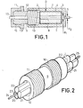
- the assembly of the three rods 20, 21, 22 has at its ends, over a determined length, a turning of diameter d 2 less than d 1 (FIG. 3).
- the axial orifice 5 of the sleeve 1 can then have two portions having diameters d 1 and d 2 respectively (FIG. 1).
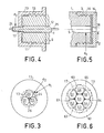
- the connector can be provided at its ends with two cylindrical covers 13 and 14 (FIGS. 4 and 5) respectively comprising axial orifices 17 and 18 of diameter substantially equal to d 2 .
- covers 13 and 14 are screwed at each end of the connector, the necked parts of the adjoining rods 20, 21, 22 engaging in the axial orifices 17 and 18 respectively, these covers 17 and 18 ensuring the proper positioning of the assembly rods 20, 21, 22 in the sleeve 7 and preventing the rotation of these three rods 20, 21, 22 about their axis.
- this inter-rod space 23 may comprise, as shown in FIG. 3, an axial flare (a conical bore 26 for example).
- this connector comprises seven rods 50 to 56, the six rods 51 to 56 being arranged around the central rod 50. All of the seven rods 50 to 56 joined together delimit six inter-rod spaces into which can be slid and connected six pairs of optical fibers 60 to 65. Each of the inter-rod spaces can be provided at its end with an axial flaring and all of the rods 50 at 56 adjoining can be turned at each end, the turned parts are inserted into the axial orifices of the covers 17 and 18 of diameter substantially equal to the diameter of the turning of all the rods 50 to 56.
- the rods 20, 21, 22 or the rods 50 to 56 may be made of ferromagnetic material and magnetized so that they repel each other in order to facilitate the insertion of the pairs of optical fibers into the spaces corresponding inter-rods.
- FIG. 7 shows a box intended to receive several connectors according to the invention.
- These connectors C 1 , C 2 , C 3 ... are held by pairs of clips 40, 41; 42, 43; ... the cables 70 and 71 of optical fibers enter the box 30 by sealed passages 72 and 73.
- the box 30, which is waterproof, is provided on one of its faces with a tube 31 for filling and d 'a degassing pipe 32, these pipes 31, 32 making it possible to introduce into the box 30, a liquid of determined index.
- a primary vacuum is created in the box 30 using the tubing 32, before the introduction by the tubing 31 of a liquid with a determined refractive index. This liquid can then fill the box 30 and enter the connectors C 1 , C 2 , C 3 , ...
Landscapes
- Physics & Mathematics (AREA)
- General Physics & Mathematics (AREA)
- Optics & Photonics (AREA)
- Mechanical Coupling Of Light Guides (AREA)
Claims (7)
Applications Claiming Priority (2)
| Application Number | Priority Date | Filing Date | Title |
|---|---|---|---|
| FR7920523A FR2463422A1 (fr) | 1979-08-10 | 1979-08-10 | Connecteur pour fibres optiques |
| FR7920523 | 1979-08-10 |
Publications (2)
| Publication Number | Publication Date |
|---|---|
| EP0024235A1 EP0024235A1 (de) | 1981-02-25 |
| EP0024235B1 true EP0024235B1 (de) | 1984-01-18 |
Family
ID=9228793
Family Applications (1)
| Application Number | Title | Priority Date | Filing Date |
|---|---|---|---|
| EP19800401157 Expired EP0024235B1 (de) | 1979-08-10 | 1980-08-06 | Verbinder für optische Fasern |
Country Status (3)
| Country | Link |
|---|---|
| EP (1) | EP0024235B1 (de) |
| DE (1) | DE3066178D1 (de) |
| FR (1) | FR2463422A1 (de) |
Families Citing this family (4)
| Publication number | Priority date | Publication date | Assignee | Title |
|---|---|---|---|---|
| FR2520515B1 (fr) * | 1982-01-27 | 1985-10-18 | Telecommunications Sa | Dispositif de raccordement de deux ensembles gaines de fibres optiques et moyens de support et d'aboutement de fibres inclus dans le dispositif |
| CH659528A5 (de) * | 1982-03-16 | 1987-01-30 | V Elektrotech I V I Lenina | Einrichtung zur uebertragung und verteilung einer lichtstrahlung. |
| CH660423A5 (de) * | 1982-05-12 | 1987-04-15 | Diamond Sa | Verfahren zum zentrieren und fixieren einer lichtleitfaser in einem lichtleiterendstueck, nach diesem verfahren hergestelltes lichtleiterendstueck, und vorrichtung zur durchfuehrung des verfahrens. |
| CN105891970A (zh) * | 2016-06-07 | 2016-08-24 | 苏州禾昌聚合材料股份有限公司 | 一种光纤适配器 |
Family Cites Families (3)
| Publication number | Priority date | Publication date | Assignee | Title |
|---|---|---|---|---|
| DE2602661C3 (de) * | 1976-01-24 | 1981-01-08 | Felten & Guilleaume Carlswerk Ag, 5000 Koeln | Kopplungsvorrichtung für Lichtleitfasern |
| IT1072041B (it) * | 1976-11-25 | 1985-04-10 | Cselt Centro Studi Lab Telecom | Sistema per l effettuazione di guinti in cavi ottici |
| FR2386061A1 (fr) * | 1977-03-31 | 1978-10-27 | Felten & Guilleaume Carlswerk | Dispositif de couplage pour fibres conductrices de la lumiere |
-
1979
- 1979-08-10 FR FR7920523A patent/FR2463422A1/fr active Granted
-
1980
- 1980-08-06 EP EP19800401157 patent/EP0024235B1/de not_active Expired
- 1980-08-06 DE DE8080401157T patent/DE3066178D1/de not_active Expired
Also Published As
| Publication number | Publication date |
|---|---|
| EP0024235A1 (de) | 1981-02-25 |
| FR2463422A1 (fr) | 1981-02-20 |
| FR2463422B1 (de) | 1983-02-04 |
| DE3066178D1 (en) | 1984-02-23 |
Similar Documents
| Publication | Publication Date | Title |
|---|---|---|
| EP0008329B1 (de) | Vorrichtung zum Verbinden optischer Fasern | |
| EP0011011B1 (de) | Endhülle eines Verbindungsstücks für eine optische Einzelfaser und mit derartiger Endhülle versehenes Verbindungsstück | |
| FR2553199A1 (fr) | Connecteur de fibres optiques | |
| FR2493050A1 (fr) | Connecteur pour cable coaxial | |
| FR2612343A1 (fr) | Connecteur pour une ligne coaxiale a conducteur exterieur ondule ou pour un guide d'ondes a tube ondule | |
| FR2519776A1 (fr) | Appareil de raccordement et connecteur de fibres optiques | |
| FR2503877A1 (fr) | Connecteur pour fibres optiques et procede pour sa realisation | |
| FR2682487A1 (fr) | Connecteur optique, notamment sous-marin. | |
| EP0427613B1 (de) | Dichtungsvorrichtung für Kabeleinführung in einen zelligen mehrpoligen Verbinder | |
| EP0024235B1 (de) | Verbinder für optische Fasern | |
| FR2588387A1 (fr) | Element de connecteur hermaphrodite pour fibres optiques | |
| FR2689650A1 (fr) | Ensemble d'accumulation de fibres optiques pour répéteur de télécommunications. | |
| EP0036814B1 (de) | Kupplungshülse für optische Monofaser-Verbinder und mit einer solchen Hülse versehener Verbinder | |
| EP0014610A1 (de) | Lösbare Verbindungsvorrichtung für optische Fasern | |
| EP0016911A1 (de) | Rohrförmiger Verbinder zum Ausrichten zweier zylindrischer Teile, insbesondere zum Ausrichten zweier optischer Fasern | |
| FR2780209A1 (fr) | Procede de raccordement de cables, et dispositif pour sa mise en oeuvre | |
| FR2526174A1 (fr) | Perfectionnements aux dispositifs de liaison optique | |
| FR2512218A1 (fr) | Connecteur de fibres optiques | |
| EP0068423B1 (de) | Verbindung für optische Monofasern | |
| FR2546308A1 (fr) | Traversee etanche pour fibres optiques | |
| EP0483338B1 (de) | Optisches verbindungssystem zur anwendung in der übertragung von video-signalen | |
| EP0034987A1 (de) | Verbindungsvorrichtung für optische Fasern | |
| CA1119859A (en) | Guide-connector assembly for joining optical fibers | |
| FR3085238A1 (fr) | Dispositif d'etancheite du type presse-etoupe pour un cable electrique | |
| EP0508884B1 (de) | Verbinder für optische Faserkabel |
Legal Events
| Date | Code | Title | Description |
|---|---|---|---|
| PUAI | Public reference made under article 153(3) epc to a published international application that has entered the european phase |
Free format text: ORIGINAL CODE: 0009012 |
|
| AK | Designated contracting states |
Designated state(s): DE GB IT |
|
| 17P | Request for examination filed |
Effective date: 19810313 |
|
| ITF | It: translation for a ep patent filed | ||
| RBV | Designated contracting states (corrected) |
Designated state(s): DE GB IT |
|
| GRAA | (expected) grant |
Free format text: ORIGINAL CODE: 0009210 |
|
| AK | Designated contracting states |
Designated state(s): DE GB IT |
|
| REF | Corresponds to: |
Ref document number: 3066178 Country of ref document: DE Date of ref document: 19840223 |
|
| PGFP | Annual fee paid to national office [announced via postgrant information from national office to epo] |
Ref country code: DE Payment date: 19840723 Year of fee payment: 5 |
|
| PLBE | No opposition filed within time limit |
Free format text: ORIGINAL CODE: 0009261 |
|
| STAA | Information on the status of an ep patent application or granted ep patent |
Free format text: STATUS: NO OPPOSITION FILED WITHIN TIME LIMIT |
|
| 26N | No opposition filed | ||
| PG25 | Lapsed in a contracting state [announced via postgrant information from national office to epo] |
Ref country code: DE Effective date: 19880503 |
|
| GBPC | Gb: european patent ceased through non-payment of renewal fee | ||
| PG25 | Lapsed in a contracting state [announced via postgrant information from national office to epo] |
Ref country code: GB Free format text: LAPSE BECAUSE OF NON-PAYMENT OF DUE FEES Effective date: 19881118 |