EP0024235B1 - Connector for optical fibres - Google Patents
Connector for optical fibres Download PDFInfo
- Publication number
- EP0024235B1 EP0024235B1 EP19800401157 EP80401157A EP0024235B1 EP 0024235 B1 EP0024235 B1 EP 0024235B1 EP 19800401157 EP19800401157 EP 19800401157 EP 80401157 A EP80401157 A EP 80401157A EP 0024235 B1 EP0024235 B1 EP 0024235B1
- Authority
- EP
- European Patent Office
- Prior art keywords
- rods
- assembly
- sheath
- diameter
- cylindrical
- Prior art date
- Legal status (The legal status is an assumption and is not a legal conclusion. Google has not performed a legal analysis and makes no representation as to the accuracy of the status listed.)
- Expired
Links
Images

Classifications
-
- G—PHYSICS
- G02—OPTICS
- G02B—OPTICAL ELEMENTS, SYSTEMS OR APPARATUS
- G02B6/00—Light guides; Structural details of arrangements comprising light guides and other optical elements, e.g. couplings
- G02B6/24—Coupling light guides
- G02B6/36—Mechanical coupling means
- G02B6/38—Mechanical coupling means having fibre to fibre mating means
- G02B6/3807—Dismountable connectors, i.e. comprising plugs
- G02B6/3833—Details of mounting fibres in ferrules; Assembly methods; Manufacture
- G02B6/3834—Means for centering or aligning the light guide within the ferrule
- G02B6/3841—Means for centering or aligning the light guide within the ferrule using rods, balls for light guides
-
- G—PHYSICS
- G02—OPTICS
- G02B—OPTICAL ELEMENTS, SYSTEMS OR APPARATUS
- G02B6/00—Light guides; Structural details of arrangements comprising light guides and other optical elements, e.g. couplings
- G02B6/24—Coupling light guides
- G02B6/36—Mechanical coupling means
- G02B6/38—Mechanical coupling means having fibre to fibre mating means
- G02B6/3801—Permanent connections, i.e. wherein fibres are kept aligned by mechanical means
- G02B6/3806—Semi-permanent connections, i.e. wherein the mechanical means keeping the fibres aligned allow for removal of the fibres
-
- G—PHYSICS
- G02—OPTICS
- G02B—OPTICAL ELEMENTS, SYSTEMS OR APPARATUS
- G02B6/00—Light guides; Structural details of arrangements comprising light guides and other optical elements, e.g. couplings
- G02B6/24—Coupling light guides
- G02B6/36—Mechanical coupling means
- G02B6/38—Mechanical coupling means having fibre to fibre mating means
- G02B6/3807—Dismountable connectors, i.e. comprising plugs
- G02B6/3833—Details of mounting fibres in ferrules; Assembly methods; Manufacture
- G02B6/3834—Means for centering or aligning the light guide within the ferrule
- G02B6/3841—Means for centering or aligning the light guide within the ferrule using rods, balls for light guides
- G02B6/3842—Means for centering or aligning the light guide within the ferrule using rods, balls for light guides for a plurality of light guides
-
- G—PHYSICS
- G02—OPTICS
- G02B—OPTICAL ELEMENTS, SYSTEMS OR APPARATUS
- G02B6/00—Light guides; Structural details of arrangements comprising light guides and other optical elements, e.g. couplings
- G02B6/44—Mechanical structures for providing tensile strength and external protection for fibres, e.g. optical transmission cables
- G02B6/4401—Optical cables
- G02B6/4415—Cables for special applications
- G02B6/4427—Pressure resistant cables, e.g. undersea cables
- G02B6/4428—Penetrator systems in pressure-resistant devices
-
- G—PHYSICS
- G02—OPTICS
- G02B—OPTICAL ELEMENTS, SYSTEMS OR APPARATUS
- G02B6/00—Light guides; Structural details of arrangements comprising light guides and other optical elements, e.g. couplings
- G02B6/24—Coupling light guides
- G02B6/36—Mechanical coupling means
- G02B6/38—Mechanical coupling means having fibre to fibre mating means
- G02B6/3807—Dismountable connectors, i.e. comprising plugs
- G02B6/381—Dismountable connectors, i.e. comprising plugs of the ferrule type, e.g. fibre ends embedded in ferrules, connecting a pair of fibres
- G02B6/3818—Dismountable connectors, i.e. comprising plugs of the ferrule type, e.g. fibre ends embedded in ferrules, connecting a pair of fibres of a low-reflection-loss type
- G02B6/382—Dismountable connectors, i.e. comprising plugs of the ferrule type, e.g. fibre ends embedded in ferrules, connecting a pair of fibres of a low-reflection-loss type with index-matching medium between light guides
-
- G—PHYSICS
- G02—OPTICS
- G02B—OPTICAL ELEMENTS, SYSTEMS OR APPARATUS
- G02B6/00—Light guides; Structural details of arrangements comprising light guides and other optical elements, e.g. couplings
- G02B6/24—Coupling light guides
- G02B6/36—Mechanical coupling means
- G02B6/38—Mechanical coupling means having fibre to fibre mating means
- G02B6/3807—Dismountable connectors, i.e. comprising plugs
- G02B6/3873—Connectors using guide surfaces for aligning ferrule ends, e.g. tubes, sleeves, V-grooves, rods, pins, balls
- G02B6/3885—Multicore or multichannel optical connectors, i.e. one single ferrule containing more than one fibre, e.g. ribbon type
Definitions
- the invention relates to fiber optic connection systems and more particularly relates to a self-centering connector allowing end-to-end splicing of at least one pair of optical fibers.
- connection means ensuring good optical continuity in the connected fibers.
- the fibers serving as a guide for optical radiation consist of two coaxial refractive media formed by a central part (or core) of circular section, with high refractive index, and by a coaxial annular part (or sheath) of index less Student.
- the radial index variation is determined so as to completely reflect the radiation at the sheath level so as to propagate this radiation in the central part of the optical fiber.
- optical fibers are very small, the central part or core of the fiber having, depending on the propagation case, diameters between a few microns and a few hundred microns.
- the end-to-end connection of two of these fibers therefore requires very high assembly precision.
- Document FR-A-2 386 061 discloses a fiber connector comprising three rods compressed radially by a double metal cone.
- DE-OS-2 602 661 a self-centering connector with three rods, in which the tightening of the rods is obtained by elastic deformation of seals when screwing two plugs threaded at each end of the rods.
- This device only allows punctual tightening of the rods, and the rods are not clamped against each other at the place where the fibers are butted.
- This device requires, moreover for its production, several mechanical parts which increase the cost.
- the present invention relates to a device which does not have these drawbacks.
- This device is defined in claim 1.
- the assembly of the three rods 20, 21, 22 has at its ends, over a determined length, a turning of diameter d 2 less than d 1 (FIG. 3).
- the axial orifice 5 of the sleeve 1 can then have two portions having diameters d 1 and d 2 respectively (FIG. 1).
- the connector can be provided at its ends with two cylindrical covers 13 and 14 (FIGS. 4 and 5) respectively comprising axial orifices 17 and 18 of diameter substantially equal to d 2 .
- covers 13 and 14 are screwed at each end of the connector, the necked parts of the adjoining rods 20, 21, 22 engaging in the axial orifices 17 and 18 respectively, these covers 17 and 18 ensuring the proper positioning of the assembly rods 20, 21, 22 in the sleeve 7 and preventing the rotation of these three rods 20, 21, 22 about their axis.
- this inter-rod space 23 may comprise, as shown in FIG. 3, an axial flare (a conical bore 26 for example).
- this connector comprises seven rods 50 to 56, the six rods 51 to 56 being arranged around the central rod 50. All of the seven rods 50 to 56 joined together delimit six inter-rod spaces into which can be slid and connected six pairs of optical fibers 60 to 65. Each of the inter-rod spaces can be provided at its end with an axial flaring and all of the rods 50 at 56 adjoining can be turned at each end, the turned parts are inserted into the axial orifices of the covers 17 and 18 of diameter substantially equal to the diameter of the turning of all the rods 50 to 56.
- the rods 20, 21, 22 or the rods 50 to 56 may be made of ferromagnetic material and magnetized so that they repel each other in order to facilitate the insertion of the pairs of optical fibers into the spaces corresponding inter-rods.
- FIG. 7 shows a box intended to receive several connectors according to the invention.
- These connectors C 1 , C 2 , C 3 ... are held by pairs of clips 40, 41; 42, 43; ... the cables 70 and 71 of optical fibers enter the box 30 by sealed passages 72 and 73.
- the box 30, which is waterproof, is provided on one of its faces with a tube 31 for filling and d 'a degassing pipe 32, these pipes 31, 32 making it possible to introduce into the box 30, a liquid of determined index.
- a primary vacuum is created in the box 30 using the tubing 32, before the introduction by the tubing 31 of a liquid with a determined refractive index. This liquid can then fill the box 30 and enter the connectors C 1 , C 2 , C 3 , ...
Description
L'invention se rapporte aux systèmes de connexion de fibres optiques et concerne plus particulièrement un connecteur autocentrant permettant un épissurage bout à bout d'au moins une paire de fibres optiques.The invention relates to fiber optic connection systems and more particularly relates to a self-centering connector allowing end-to-end splicing of at least one pair of optical fibers.
L'utilisation des fibres optiques nécessite des moyens de connexion assurant une bonne continuité optique dans les fibres connectées.The use of optical fibers requires connection means ensuring good optical continuity in the connected fibers.
Les fibres servant de guide aux rayonnements optiques sont constituées par deux milieux réfringents coaxiaux formés d'une partie centrale (ou âme) de section circulaire, à haut indice de réfraction, et d'une partie annulaire coaxiale (ou gaine) d'indice moins élevé. La variation radiale d'indice est déterminée de façon à réfléchir totalement le rayonnement au niveau de gaine de façon à propager ce rayonnement dans la partie centrale de la fibre optique.The fibers serving as a guide for optical radiation consist of two coaxial refractive media formed by a central part (or core) of circular section, with high refractive index, and by a coaxial annular part (or sheath) of index less Student. The radial index variation is determined so as to completely reflect the radiation at the sheath level so as to propagate this radiation in the central part of the optical fiber.
Ces fibres optiques sont de très petites dimensions, la partie centrale ou âme de la fibre ayant, suivant les cas de propagation, des diamètres compris entre quelques microns et quelques centaines de microns. La connexion bout à bout de deux de ces fibres nécessite donc une très grande précision de montage.These optical fibers are very small, the central part or core of the fiber having, depending on the propagation case, diameters between a few microns and a few hundred microns. The end-to-end connection of two of these fibers therefore requires very high assembly precision.
Il est connu d'utiliser des embouts multi-fibres à rangement hexagonal, ces embouts étant munis d'un système de détrompage. Il est également connu de maintenir en position convenable une fibre optique au moyen de trois tiges rigides insérées dans un manchon rétractable et muni de moyens de pincement mécaniques. Mais cette solution conduit à un positionnement imprécis de la fibre par rapport à l'axe du système de connexion.It is known to use multi-fiber tips with hexagonal storage, these tips being provided with a keying system. It is also known to keep an optical fiber in a suitable position by means of three rigid rods inserted in a retractable sleeve and provided with mechanical pinching means. However, this solution leads to imprecise positioning of the fiber relative to the axis of the connection system.
On connaît du document FR-A-2 386 061 un connecteur de fibres comportant trois tiges comprimées radialement par un double cône métallique.Document FR-A-2 386 061 discloses a fiber connector comprising three rods compressed radially by a double metal cone.
On connaît de la demande de brevet allemand . DE-OS-2 602 661 un connecteur auto-centrant à trois tiges, dans lequel le serrage des tiges est obtenu par déformation élastique de joints lors du vissage de deux bouchons enfilés à chaque extrémité des tiges.We know of the German patent application. DE-OS-2 602 661 a self-centering connector with three rods, in which the tightening of the rods is obtained by elastic deformation of seals when screwing two plugs threaded at each end of the rods.
Ce dispositif ne permet qu'un serrage ponctuel des tiges, et les tiges ne sont pas serrées les unes contre les autres à l'endroit où les fibres sont aboutées.This device only allows punctual tightening of the rods, and the rods are not clamped against each other at the place where the fibers are butted.
Ce dispositif demande, en outre pour sa réalisation, plusieurs pièces mécaniques qui en grèvent le coût.This device requires, moreover for its production, several mechanical parts which increase the cost.
La présente invention a pour objet un dispositif ne présentant pas ces inconvénients. Ce dispositif est défini dans la revendication 1.The present invention relates to a device which does not have these drawbacks. This device is defined in claim 1.
L'invention sera mieux comprise et d'autres aspects apparaîtront à l'aide de la description ci-après et des dessins qui l'accompagnent et sur lesquels :
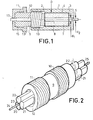
- la figure 1 représente, en coupe longitudinale, un connecteur de fibres optiques suivant l'invention ;
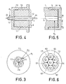
- les figures 2 à 5 montrent des détails de réalisation du connecteur suivant l'invention ;
- la figure 6 montre un détail d'un autre exemple de réalisation d'un connecteur de fibres optiques suivant l'invention ;
- la figure 7 montre, en coupe, un coffret dans lequel sont disposés plusieurs connecteurs suivant l'invention.
- FIG. 1 represents, in longitudinal section, a connector of optical fibers according to the invention;
- Figures 2 to 5 show details of embodiment of the connector according to the invention;
- Figure 6 shows a detail of another embodiment of an optical fiber connector according to the invention;
- Figure 7 shows, in section, a box in which are arranged several connectors according to the invention.
Dans un exemple de réalisation, le connecteur suivant l'invention comporte, comme montré en figures 1 et 2 :
- - trois
tiges espace 23 inter-tiges dans lequel peuvent être glissées des fibres optiques 24, 25. Le diamètre de ces fibres optiques 24, 25 est sensiblement égal au diamètre du cercle inscrit dans l'espace 23 inter-tiges ; - - un fourreau 1 cylindrique (figure 1), en matériau métallique par exemple, ce fourreau 1 étant fermé à l'une de ses extrémités par une
paroi 3 munie d'un orifice 5 axial de diamètre d1, ce fourreau comportant à son autre extrémité unfiletage 2 intérieur ; - - un
manchon 7 cylindrique, en matériau élastique et incompressible, c'est-à-dire déformable mais de volume sensiblement constant, muni axialement d'uncanal 8 de diamètre d1, ce diamètre d1 étant sensiblement égal au diamètre du cercle circonscrit à l'ensemble destiges manchon 7 étant un peu inférieur au diamètre intérieur du fourreau 1 dans lequel il est destiné à être placé ; - - un
bouchon 9 de serrage (figures 1 et 2) en matériau métallique par exemple, muni axialement d'uncanal 12, de diamètre d1, cebouchon 9, qui comporte à l'une de ses extrémités unfiletage 10 extérieur, étant destiné à venir se visser dans lefiletage 2 intérieur du fourreau 1.
- - Three
identical metal rods inter-rod space 23 in whichoptical fibers optical fibers space 23 between rods; - a cylindrical sheath 1 (FIG. 1), made of metallic material for example, this sheath 1 being closed at one of its ends by a
wall 3 provided with anaxial orifice 5 of diameter d 1 , this sheath having at its other end with aninternal thread 2; - - A
cylindrical sleeve 7, made of elastic and incompressible material, that is to say deformable but of substantially constant volume, provided axially with achannel 8 of diameter d 1 , this diameter d 1 being substantially equal to the diameter of the circumscribed circle to all of therods sleeve 7 is slightly less than the inside diameter of the sleeve 1 in which it is intended to be placed; - - A tightening plug 9 (Figures 1 and 2) in metallic material for example, provided axially with a
channel 12, of diameter d 1 , thisplug 9, which comprises at one of its ends anexternal thread 10, being intended to be screwed into theinternal thread 2 of the sleeve 1.
L'opération de connexion des fibres optiques 24, 25 s'effectue de la façon suivante :
- - les trois
tiges manchon 7 élastique, lui- même placé dans le fourreau 1, ces troistiges espace 23 inter-tiges dans lequel sont glissées lesfibres 24 et 25 à connecter. Lorsque ces fibres optiques 24, 25 sont au contact l'une de l'autre, lebouchon 9, dont lecanal 12 est traversé par l'ensemble destiges manchon 7 élastique qui comprime à son tour radialement les troistiges
- the three
rods elastic sleeve 7, itself placed in the sheath 1, these threerods space 23 between rods in which thefibers 24 are slid and 25 to connect. When theseoptical fibers plug 9, thechannel 12 of which is crossed by all of therods elastic sleeve 7 which in turn compresses radially the threerods optical fibers
Dans un autre exemple de réalisation, l'assemblage des trois tiges 20, 21, 22 présente à ses extrémités, sur une longueur déterminée, un décolletage de diamètre d2 inférieur à d1 (figure 3). L'orifice axial 5 du fourreau 1 peut alors présenter deux portions ayant respectivement des diamètres d1 et d2 (figure 1). Dans un autre exemple de réalisation, le connecteur peut être muni à ses extrémités de deux capots 13 et 14 cylindriques (figures 4 et 5) comportant respectivement des orifices axiaux 17 et 18 de diamètre sensiblement égal à d2. Ces capots 13 et 14 viennent se visser à chaque extrémité du connecteur, les parties décolletées des tiges accolées 20, 21, 22 s'engageant dans les orifices axiaux 17 et 18 respectivement, ces capots 17 et 18 assurant le positionnement convenable de l'ensemble des tiges 20, 21, 22 dans le manchon 7 et empêchant la rotation de ces trois tiges 20, 21, 22 autour de leur axe.In another exemplary embodiment, the assembly of the three
Afin de faciliter l'introduction des fibres optiques dans l'espace inter-tiges 23, cet espace 23 inter-tiges peut comporter, comme le montre la figure 3, un évasement axial (un alésage conique 26 par exemple).In order to facilitate the introduction of the optical fibers into the
Dans un autre exemple de réalisation d'un connecteur suivant l'invention, montré en figure 6, ce connecteur comporte sept tiges 50 à 56, les six tiges 51 à 56 étant arrangées autour de la tige centrale 50. L'ensemble des sept tiges 50 à 56 accolées délimitent six espaces inter-tiges dans lesquels peuvent être glissées et connectées six paires de fibres optiques 60 à 65. Chacun des espaces inter-tiges peut être muni à son extrémité d'un évasement axial et l'ensemble des tiges 50 à 56 accolées peut être décolleté à chaque extrémité, les parties décolletées venant s'insérer dans les orifices axiaux des capots 17 et 18 de diamètre sensiblement égal au diamètre du décolletage de l'ensemble des tiges 50 à 56.In another embodiment of a connector according to the invention, shown in FIG. 6, this connector comprises seven
Dans les exemples décrits et représentés, les tiges 20, 21, 22 ou les tiges 50 à 56 peuvent être en matériau ferromagnétique et aimantées de telle sorte qu'elles se repoussent mutuellement afin de faciliter l'insertion des paires de fibres optiques dans les espaces inter-tiges correspondants.In the examples described and shown, the
La figure 7 montre un coffret destiné à recevoir plusieurs connecteurs suivant l'invention. Ces connecteurs C1, C2, C3 ... sont maintenus par des paires de clips 40, 41 ; 42, 43 ; ... les câbles 70 et 71 de fibres optiques pénètrent dans le coffret 30 par des passages étanches 72 et 73. Le coffret 30, qui est étanche, est muni sur l'une de ses faces d'une tubulure 31 de remplissage et d'une tubulure 32 de dégazage, ces tubulures 31, 32 permettant d'introduire dans le coffret 30, un liquide d'indice déterminé. Un vide primaire est effectué dans le coffret 30 en utilisant la tubulure 32, avant l'introduction par la tubulure 31 d'un liquide d'indice de réfraction déterminé. Ce liquide peut alors remplir le coffret 30 et pénétrer dans les connecteurs C1, C2, C3, ...FIG. 7 shows a box intended to receive several connectors according to the invention. These connectors C 1 , C 2 , C 3 ... are held by pairs of
Claims (7)
Applications Claiming Priority (2)
| Application Number | Priority Date | Filing Date | Title |
|---|---|---|---|
| FR7920523 | 1979-08-10 | ||
| FR7920523A FR2463422A1 (en) | 1979-08-10 | 1979-08-10 | CONNECTOR FOR OPTICAL FIBERS |
Publications (2)
| Publication Number | Publication Date |
|---|---|
| EP0024235A1 EP0024235A1 (en) | 1981-02-25 |
| EP0024235B1 true EP0024235B1 (en) | 1984-01-18 |
Family
ID=9228793
Family Applications (1)
| Application Number | Title | Priority Date | Filing Date |
|---|---|---|---|
| EP19800401157 Expired EP0024235B1 (en) | 1979-08-10 | 1980-08-06 | Connector for optical fibres |
Country Status (3)
| Country | Link |
|---|---|
| EP (1) | EP0024235B1 (en) |
| DE (1) | DE3066178D1 (en) |
| FR (1) | FR2463422A1 (en) |
Families Citing this family (4)
| Publication number | Priority date | Publication date | Assignee | Title |
|---|---|---|---|---|
| FR2520515B1 (en) * | 1982-01-27 | 1985-10-18 | Telecommunications Sa | DEVICE FOR CONNECTING TWO OPTICAL FIBER SHEATHING ASSEMBLIES AND MEANS FOR SUPPORTING AND FITTING FIBERS INCLUDED IN THE DEVICE |
| CH659528A5 (en) * | 1982-03-16 | 1987-01-30 | V Elektrotech I V I Lenina | DEVICE FOR TRANSMITTING AND DISTRIBUTING A LIGHT RADIATION. |
| CH660423A5 (en) * | 1982-05-12 | 1987-04-15 | Diamond Sa | METHOD FOR CENTERING AND FIXING A LIGHT-FIBER FIBER IN A LIGHT-GUIDE END PIECE, LIGHT-GUIDE END PIECE PRODUCED BY THIS METHOD, AND DEVICE FOR CARRYING OUT THE METHOD. |
| CN105891970A (en) * | 2016-06-07 | 2016-08-24 | 苏州禾昌聚合材料股份有限公司 | Optical fiber adapter |
Family Cites Families (3)
| Publication number | Priority date | Publication date | Assignee | Title |
|---|---|---|---|---|
| DE2602661C3 (en) * | 1976-01-24 | 1981-01-08 | Felten & Guilleaume Carlswerk Ag, 5000 Koeln | Coupling device for optical fibers |
| IT1072041B (en) * | 1976-11-25 | 1985-04-10 | Cselt Centro Studi Lab Telecom | SYSTEM FOR MAKING GUINTI IN OPTICAL CABLES |
| FR2386061A1 (en) * | 1977-03-31 | 1978-10-27 | Felten & Guilleaume Carlswerk | COUPLING DEVICE FOR LIGHT CONDUCTING FIBERS |
-
1979
- 1979-08-10 FR FR7920523A patent/FR2463422A1/en active Granted
-
1980
- 1980-08-06 DE DE8080401157T patent/DE3066178D1/en not_active Expired
- 1980-08-06 EP EP19800401157 patent/EP0024235B1/en not_active Expired
Also Published As
| Publication number | Publication date |
|---|---|
| FR2463422A1 (en) | 1981-02-20 |
| FR2463422B1 (en) | 1983-02-04 |
| DE3066178D1 (en) | 1984-02-23 |
| EP0024235A1 (en) | 1981-02-25 |
Similar Documents
| Publication | Publication Date | Title |
|---|---|---|
| EP0008329B1 (en) | Device for connecting optical fibres | |
| EP0011011B1 (en) | Termination for optical minofibre connector and connector provided with such a termination | |
| FR2553199A1 (en) | OPTICAL FIBER CONNECTOR | |
| FR2493050A1 (en) | CONNECTOR FOR COAXIAL CABLE | |
| FR2612343A1 (en) | CONNECTOR FOR A COAXIAL LINE WITH EXTERNAL CONDUCTOR ONDULE OR FOR A WAVEGUIDE GUIDE WITH CORRUGATED TUBE | |
| FR2519776A1 (en) | CONNECTING APPARATUS AND OPTICAL FIBER CONNECTOR | |
| EP0305247A1 (en) | Coupling arrangement between two coaxial microwave structures with different diameters | |
| FR2682487A1 (en) | OPTICAL CONNECTOR, ESPECIALLY UNDERWATER. | |
| EP0024235B1 (en) | Connector for optical fibres | |
| EP0427613A1 (en) | Sealing arrangement for cable entry into an alveolar multicontact connector | |
| FR2588387A1 (en) | HERMAPHRODITE CONNECTOR ELEMENT FOR OPTICAL FIBERS | |
| FR2689650A1 (en) | Fiber optic accumulator assembly for telecommunications repeater. | |
| EP0036814B1 (en) | Connector's coupling sleeve for optical single fibre, and connector provided with such a sleeve | |
| EP0014610A1 (en) | Detachable coupling for optical fibres | |
| EP0016911A1 (en) | Tubular connector for aligning two cylindrical parts, especially for aligning two optical fibres | |
| FR2780209A1 (en) | Sealing device for cables at entry to underground connection box | |
| FR2526174A1 (en) | IMPROVEMENTS ON OPTICAL LINK DEVICES | |
| EP0068423B1 (en) | Connector for optical monofibres | |
| FR2546308A1 (en) | Sealed penetration (lead-in) for optical fibres | |
| EP0483338B1 (en) | Optical connection system for use in the transmission of video signals | |
| EP0034987A1 (en) | Connecting device for optical fibres | |
| FR3085238A1 (en) | SEALING DEVICE OF THE GLAND TYPE FOR AN ELECTRICAL CABLE | |
| EP0508884B1 (en) | Optical fibre cable connector | |
| FR2612302A1 (en) | Device for assembling optical fibres | |
| CA1317021C (en) | Sensing device for water-borne sound waves |
Legal Events
| Date | Code | Title | Description |
|---|---|---|---|
| PUAI | Public reference made under article 153(3) epc to a published international application that has entered the european phase |
Free format text: ORIGINAL CODE: 0009012 |
|
| AK | Designated contracting states |
Designated state(s): DE GB IT |
|
| 17P | Request for examination filed |
Effective date: 19810313 |
|
| ITF | It: translation for a ep patent filed |
Owner name: JACOBACCI & PERANI S.P.A. |
|
| RBV | Designated contracting states (corrected) |
Designated state(s): DE GB IT |
|
| GRAA | (expected) grant |
Free format text: ORIGINAL CODE: 0009210 |
|
| AK | Designated contracting states |
Designated state(s): DE GB IT |
|
| REF | Corresponds to: |
Ref document number: 3066178 Country of ref document: DE Date of ref document: 19840223 |
|
| PGFP | Annual fee paid to national office [announced via postgrant information from national office to epo] |
Ref country code: DE Payment date: 19840723 Year of fee payment: 5 |
|
| PLBE | No opposition filed within time limit |
Free format text: ORIGINAL CODE: 0009261 |
|
| STAA | Information on the status of an ep patent application or granted ep patent |
Free format text: STATUS: NO OPPOSITION FILED WITHIN TIME LIMIT |
|
| 26N | No opposition filed | ||
| PG25 | Lapsed in a contracting state [announced via postgrant information from national office to epo] |
Ref country code: DE Effective date: 19880503 |
|
| GBPC | Gb: european patent ceased through non-payment of renewal fee | ||
| PG25 | Lapsed in a contracting state [announced via postgrant information from national office to epo] |
Ref country code: GB Free format text: LAPSE BECAUSE OF NON-PAYMENT OF DUE FEES Effective date: 19881118 |