EP4336522A1 - Expandierbarer gesinterter neodym-eisen-bor-magnet, herstellungsverfahren dafür und anwendung davon - Google Patents
Expandierbarer gesinterter neodym-eisen-bor-magnet, herstellungsverfahren dafür und anwendung davon Download PDFInfo
- Publication number
- EP4336522A1 EP4336522A1 EP22819665.5A EP22819665A EP4336522A1 EP 4336522 A1 EP4336522 A1 EP 4336522A1 EP 22819665 A EP22819665 A EP 22819665A EP 4336522 A1 EP4336522 A1 EP 4336522A1
- Authority
- EP
- European Patent Office
- Prior art keywords
- expandable
- coating
- iron
- expansion
- magnet
- Prior art date
- Legal status (The legal status is an assumption and is not a legal conclusion. Google has not performed a legal analysis and makes no representation as to the accuracy of the status listed.)
- Granted
Links
Images

Classifications
-
- H—ELECTRICITY
- H01—ELECTRIC ELEMENTS
- H01F—MAGNETS; INDUCTANCES; TRANSFORMERS; SELECTION OF MATERIALS FOR THEIR MAGNETIC PROPERTIES
- H01F1/00—Magnets or magnetic bodies characterised by the magnetic materials therefor; Selection of materials for their magnetic properties
- H01F1/01—Magnets or magnetic bodies characterised by the magnetic materials therefor; Selection of materials for their magnetic properties of inorganic materials
- H01F1/03—Magnets or magnetic bodies characterised by the magnetic materials therefor; Selection of materials for their magnetic properties of inorganic materials characterised by their coercivity
- H01F1/032—Magnets or magnetic bodies characterised by the magnetic materials therefor; Selection of materials for their magnetic properties of inorganic materials characterised by their coercivity of hard-magnetic materials
- H01F1/04—Magnets or magnetic bodies characterised by the magnetic materials therefor; Selection of materials for their magnetic properties of inorganic materials characterised by their coercivity of hard-magnetic materials metals or alloys
- H01F1/047—Alloys characterised by their composition
- H01F1/053—Alloys characterised by their composition containing rare earth metals
- H01F1/055—Alloys characterised by their composition containing rare earth metals and magnetic transition metals, e.g. SmCo5
- H01F1/057—Alloys characterised by their composition containing rare earth metals and magnetic transition metals, e.g. SmCo5 and IIIa elements, e.g. Nd2Fe14B
- H01F1/0571—Alloys characterised by their composition containing rare earth metals and magnetic transition metals, e.g. SmCo5 and IIIa elements, e.g. Nd2Fe14B in the form of particles, e.g. rapid quenched powders or ribbon flakes
- H01F1/0575—Alloys characterised by their composition containing rare earth metals and magnetic transition metals, e.g. SmCo5 and IIIa elements, e.g. Nd2Fe14B in the form of particles, e.g. rapid quenched powders or ribbon flakes pressed, sintered or bonded together
- H01F1/0577—Alloys characterised by their composition containing rare earth metals and magnetic transition metals, e.g. SmCo5 and IIIa elements, e.g. Nd2Fe14B in the form of particles, e.g. rapid quenched powders or ribbon flakes pressed, sintered or bonded together sintered
-
- H—ELECTRICITY
- H01—ELECTRIC ELEMENTS
- H01F—MAGNETS; INDUCTANCES; TRANSFORMERS; SELECTION OF MATERIALS FOR THEIR MAGNETIC PROPERTIES
- H01F1/00—Magnets or magnetic bodies characterised by the magnetic materials therefor; Selection of materials for their magnetic properties
- H01F1/01—Magnets or magnetic bodies characterised by the magnetic materials therefor; Selection of materials for their magnetic properties of inorganic materials
- H01F1/03—Magnets or magnetic bodies characterised by the magnetic materials therefor; Selection of materials for their magnetic properties of inorganic materials characterised by their coercivity
- H01F1/032—Magnets or magnetic bodies characterised by the magnetic materials therefor; Selection of materials for their magnetic properties of inorganic materials characterised by their coercivity of hard-magnetic materials
- H01F1/04—Magnets or magnetic bodies characterised by the magnetic materials therefor; Selection of materials for their magnetic properties of inorganic materials characterised by their coercivity of hard-magnetic materials metals or alloys
- H01F1/047—Alloys characterised by their composition
- H01F1/053—Alloys characterised by their composition containing rare earth metals
- H01F1/055—Alloys characterised by their composition containing rare earth metals and magnetic transition metals, e.g. SmCo5
- H01F1/057—Alloys characterised by their composition containing rare earth metals and magnetic transition metals, e.g. SmCo5 and IIIa elements, e.g. Nd2Fe14B
- H01F1/0571—Alloys characterised by their composition containing rare earth metals and magnetic transition metals, e.g. SmCo5 and IIIa elements, e.g. Nd2Fe14B in the form of particles, e.g. rapid quenched powders or ribbon flakes
-
- B—PERFORMING OPERATIONS; TRANSPORTING
- B22—CASTING; POWDER METALLURGY
- B22F—WORKING METALLIC POWDER; MANUFACTURE OF ARTICLES FROM METALLIC POWDER; MAKING METALLIC POWDER; APPARATUS OR DEVICES SPECIALLY ADAPTED FOR METALLIC POWDER
- B22F3/00—Manufacture of workpieces or articles from metallic powder characterised by the manner of compacting or sintering; Apparatus specially adapted therefor ; Presses and furnaces
- B22F3/24—After-treatment of workpieces or articles
-
- C—CHEMISTRY; METALLURGY
- C22—METALLURGY; FERROUS OR NON-FERROUS ALLOYS; TREATMENT OF ALLOYS OR NON-FERROUS METALS
- C22C—ALLOYS
- C22C38/00—Ferrous alloys, e.g. steel alloys
- C22C38/002—Ferrous alloys, e.g. steel alloys containing In, Mg, or other elements not provided for in one single group C22C38/001 - C22C38/60
-
- C—CHEMISTRY; METALLURGY
- C22—METALLURGY; FERROUS OR NON-FERROUS ALLOYS; TREATMENT OF ALLOYS OR NON-FERROUS METALS
- C22C—ALLOYS
- C22C38/00—Ferrous alloys, e.g. steel alloys
- C22C38/005—Ferrous alloys, e.g. steel alloys containing rare earths, i.e. Sc, Y, Lanthanides
-
- H—ELECTRICITY
- H01—ELECTRIC ELEMENTS
- H01F—MAGNETS; INDUCTANCES; TRANSFORMERS; SELECTION OF MATERIALS FOR THEIR MAGNETIC PROPERTIES
- H01F1/00—Magnets or magnetic bodies characterised by the magnetic materials therefor; Selection of materials for their magnetic properties
- H01F1/01—Magnets or magnetic bodies characterised by the magnetic materials therefor; Selection of materials for their magnetic properties of inorganic materials
- H01F1/03—Magnets or magnetic bodies characterised by the magnetic materials therefor; Selection of materials for their magnetic properties of inorganic materials characterised by their coercivity
- H01F1/032—Magnets or magnetic bodies characterised by the magnetic materials therefor; Selection of materials for their magnetic properties of inorganic materials characterised by their coercivity of hard-magnetic materials
- H01F1/04—Magnets or magnetic bodies characterised by the magnetic materials therefor; Selection of materials for their magnetic properties of inorganic materials characterised by their coercivity of hard-magnetic materials metals or alloys
- H01F1/047—Alloys characterised by their composition
- H01F1/053—Alloys characterised by their composition containing rare earth metals
- H01F1/055—Alloys characterised by their composition containing rare earth metals and magnetic transition metals, e.g. SmCo5
- H01F1/057—Alloys characterised by their composition containing rare earth metals and magnetic transition metals, e.g. SmCo5 and IIIa elements, e.g. Nd2Fe14B
- H01F1/0571—Alloys characterised by their composition containing rare earth metals and magnetic transition metals, e.g. SmCo5 and IIIa elements, e.g. Nd2Fe14B in the form of particles, e.g. rapid quenched powders or ribbon flakes
- H01F1/0575—Alloys characterised by their composition containing rare earth metals and magnetic transition metals, e.g. SmCo5 and IIIa elements, e.g. Nd2Fe14B in the form of particles, e.g. rapid quenched powders or ribbon flakes pressed, sintered or bonded together
- H01F1/0576—Alloys characterised by their composition containing rare earth metals and magnetic transition metals, e.g. SmCo5 and IIIa elements, e.g. Nd2Fe14B in the form of particles, e.g. rapid quenched powders or ribbon flakes pressed, sintered or bonded together pressed, e.g. hot working
-
- H—ELECTRICITY
- H01—ELECTRIC ELEMENTS
- H01F—MAGNETS; INDUCTANCES; TRANSFORMERS; SELECTION OF MATERIALS FOR THEIR MAGNETIC PROPERTIES
- H01F1/00—Magnets or magnetic bodies characterised by the magnetic materials therefor; Selection of materials for their magnetic properties
- H01F1/01—Magnets or magnetic bodies characterised by the magnetic materials therefor; Selection of materials for their magnetic properties of inorganic materials
- H01F1/03—Magnets or magnetic bodies characterised by the magnetic materials therefor; Selection of materials for their magnetic properties of inorganic materials characterised by their coercivity
- H01F1/032—Magnets or magnetic bodies characterised by the magnetic materials therefor; Selection of materials for their magnetic properties of inorganic materials characterised by their coercivity of hard-magnetic materials
- H01F1/04—Magnets or magnetic bodies characterised by the magnetic materials therefor; Selection of materials for their magnetic properties of inorganic materials characterised by their coercivity of hard-magnetic materials metals or alloys
- H01F1/047—Alloys characterised by their composition
- H01F1/053—Alloys characterised by their composition containing rare earth metals
- H01F1/055—Alloys characterised by their composition containing rare earth metals and magnetic transition metals, e.g. SmCo5
- H01F1/057—Alloys characterised by their composition containing rare earth metals and magnetic transition metals, e.g. SmCo5 and IIIa elements, e.g. Nd2Fe14B
- H01F1/0571—Alloys characterised by their composition containing rare earth metals and magnetic transition metals, e.g. SmCo5 and IIIa elements, e.g. Nd2Fe14B in the form of particles, e.g. rapid quenched powders or ribbon flakes
- H01F1/0575—Alloys characterised by their composition containing rare earth metals and magnetic transition metals, e.g. SmCo5 and IIIa elements, e.g. Nd2Fe14B in the form of particles, e.g. rapid quenched powders or ribbon flakes pressed, sintered or bonded together
- H01F1/0578—Alloys characterised by their composition containing rare earth metals and magnetic transition metals, e.g. SmCo5 and IIIa elements, e.g. Nd2Fe14B in the form of particles, e.g. rapid quenched powders or ribbon flakes pressed, sintered or bonded together bonded together
-
- H—ELECTRICITY
- H01—ELECTRIC ELEMENTS
- H01F—MAGNETS; INDUCTANCES; TRANSFORMERS; SELECTION OF MATERIALS FOR THEIR MAGNETIC PROPERTIES
- H01F41/00—Apparatus or processes specially adapted for manufacturing or assembling magnets, inductances or transformers; Apparatus or processes specially adapted for manufacturing materials characterised by their magnetic properties
- H01F41/02—Apparatus or processes specially adapted for manufacturing or assembling magnets, inductances or transformers; Apparatus or processes specially adapted for manufacturing materials characterised by their magnetic properties for manufacturing cores, coils, or magnets
- H01F41/0253—Apparatus or processes specially adapted for manufacturing or assembling magnets, inductances or transformers; Apparatus or processes specially adapted for manufacturing materials characterised by their magnetic properties for manufacturing cores, coils, or magnets for manufacturing permanent magnets
- H01F41/026—Apparatus or processes specially adapted for manufacturing or assembling magnets, inductances or transformers; Apparatus or processes specially adapted for manufacturing materials characterised by their magnetic properties for manufacturing cores, coils, or magnets for manufacturing permanent magnets protecting methods against environmental influences, e.g. oxygen, by surface treatment
-
- H—ELECTRICITY
- H01—ELECTRIC ELEMENTS
- H01F—MAGNETS; INDUCTANCES; TRANSFORMERS; SELECTION OF MATERIALS FOR THEIR MAGNETIC PROPERTIES
- H01F41/00—Apparatus or processes specially adapted for manufacturing or assembling magnets, inductances or transformers; Apparatus or processes specially adapted for manufacturing materials characterised by their magnetic properties
- H01F41/02—Apparatus or processes specially adapted for manufacturing or assembling magnets, inductances or transformers; Apparatus or processes specially adapted for manufacturing materials characterised by their magnetic properties for manufacturing cores, coils, or magnets
- H01F41/0253—Apparatus or processes specially adapted for manufacturing or assembling magnets, inductances or transformers; Apparatus or processes specially adapted for manufacturing materials characterised by their magnetic properties for manufacturing cores, coils, or magnets for manufacturing permanent magnets
- H01F41/0266—Moulding; Pressing
-
- H—ELECTRICITY
- H01—ELECTRIC ELEMENTS
- H01F—MAGNETS; INDUCTANCES; TRANSFORMERS; SELECTION OF MATERIALS FOR THEIR MAGNETIC PROPERTIES
- H01F7/00—Magnets
- H01F7/02—Permanent magnets [PM]
- H01F7/0205—Magnetic circuits with PM in general
- H01F7/0221—Mounting means for PM, supporting, coating, encapsulating PM
-
- H—ELECTRICITY
- H02—GENERATION; CONVERSION OR DISTRIBUTION OF ELECTRIC POWER
- H02K—DYNAMO-ELECTRIC MACHINES
- H02K1/00—Details of the magnetic circuit
- H02K1/02—Details of the magnetic circuit characterised by the magnetic material
-
- B—PERFORMING OPERATIONS; TRANSPORTING
- B22—CASTING; POWDER METALLURGY
- B22F—WORKING METALLIC POWDER; MANUFACTURE OF ARTICLES FROM METALLIC POWDER; MAKING METALLIC POWDER; APPARATUS OR DEVICES SPECIALLY ADAPTED FOR METALLIC POWDER
- B22F3/00—Manufacture of workpieces or articles from metallic powder characterised by the manner of compacting or sintering; Apparatus specially adapted therefor ; Presses and furnaces
- B22F3/24—After-treatment of workpieces or articles
- B22F2003/241—Chemical after-treatment on the surface
- B22F2003/242—Coating
-
- B—PERFORMING OPERATIONS; TRANSPORTING
- B22—CASTING; POWDER METALLURGY
- B22F—WORKING METALLIC POWDER; MANUFACTURE OF ARTICLES FROM METALLIC POWDER; MAKING METALLIC POWDER; APPARATUS OR DEVICES SPECIALLY ADAPTED FOR METALLIC POWDER
- B22F3/00—Manufacture of workpieces or articles from metallic powder characterised by the manner of compacting or sintering; Apparatus specially adapted therefor ; Presses and furnaces
- B22F3/24—After-treatment of workpieces or articles
- B22F2003/247—Removing material: carving, cleaning, grinding, hobbing, honing, lapping, polishing, milling, shaving, skiving, turning the surface
-
- B—PERFORMING OPERATIONS; TRANSPORTING
- B22—CASTING; POWDER METALLURGY
- B22F—WORKING METALLIC POWDER; MANUFACTURE OF ARTICLES FROM METALLIC POWDER; MAKING METALLIC POWDER; APPARATUS OR DEVICES SPECIALLY ADAPTED FOR METALLIC POWDER
- B22F3/00—Manufacture of workpieces or articles from metallic powder characterised by the manner of compacting or sintering; Apparatus specially adapted therefor ; Presses and furnaces
- B22F3/24—After-treatment of workpieces or articles
- B22F2003/248—Thermal after-treatment
-
- B—PERFORMING OPERATIONS; TRANSPORTING
- B22—CASTING; POWDER METALLURGY
- B22F—WORKING METALLIC POWDER; MANUFACTURE OF ARTICLES FROM METALLIC POWDER; MAKING METALLIC POWDER; APPARATUS OR DEVICES SPECIALLY ADAPTED FOR METALLIC POWDER
- B22F2301/00—Metallic composition of the powder or its coating
- B22F2301/35—Iron
- B22F2301/355—Rare Earth - Fe intermetallic alloys
-
- B—PERFORMING OPERATIONS; TRANSPORTING
- B22—CASTING; POWDER METALLURGY
- B22F—WORKING METALLIC POWDER; MANUFACTURE OF ARTICLES FROM METALLIC POWDER; MAKING METALLIC POWDER; APPARATUS OR DEVICES SPECIALLY ADAPTED FOR METALLIC POWDER
- B22F2998/00—Supplementary information concerning processes or compositions relating to powder metallurgy
- B22F2998/10—Processes characterised by the sequence of their steps
-
- B—PERFORMING OPERATIONS; TRANSPORTING
- B22—CASTING; POWDER METALLURGY
- B22F—WORKING METALLIC POWDER; MANUFACTURE OF ARTICLES FROM METALLIC POWDER; MAKING METALLIC POWDER; APPARATUS OR DEVICES SPECIALLY ADAPTED FOR METALLIC POWDER
- B22F2999/00—Aspects linked to processes or compositions used in powder metallurgy
-
- H—ELECTRICITY
- H02—GENERATION; CONVERSION OR DISTRIBUTION OF ELECTRIC POWER
- H02K—DYNAMO-ELECTRIC MACHINES
- H02K15/00—Processes or apparatus specially adapted for manufacturing, assembling, maintaining or repairing of dynamo-electric machines
- H02K15/02—Processes or apparatus specially adapted for manufacturing, assembling, maintaining or repairing of dynamo-electric machines of stator or rotor bodies
- H02K15/03—Processes or apparatus specially adapted for manufacturing, assembling, maintaining or repairing of dynamo-electric machines of stator or rotor bodies having permanent magnets
Definitions
- the present disclosure relates to the technical field of surface protection of magnetic materials, in particular to an expandable sintered neodymium-iron-boron magnet, a preparation method therefor and use thereof.
- the sintered neodymium-iron-boron magnet is known as the modem "magnet king" due to excellent remanence, coercivity, and magnetic energy product, and thus is widely applied to the industries of energy, transportation, machinery, medical care, IT, household appliances, and the like. Particularly, the demand and application of the sintered neodymium-iron-boron magnet are expanding along with the development and utilization of new energy.
- the sintered neodymium-iron-boron magnet greatly promotes the development of the permanent magnet motor, so that the sintered neodymium-iron-boron permanent magnet is used to replace the original product equipped with a ferrite or samarium-cobalt magnet as a motor stator or rotor, thereby reducing the weight of the motor, improving the power coefficient, and increasing the output power.
- the sintered neodymium-iron-boron consists of a main phase Nd 2 Fe 14 B, an Nd-rich phase, and a B-rich phase, in which the metal Nd element has the strongest chemical activity and is extremely easy to corrode in humid, high-temperature and electrochemical environments, so that the further expansion of the application fields of the sintered neodymium-iron-boron magnet are greatly limited.
- an electrophoretic epoxy resin coating is commonly used for surface protection in the motor industry.
- the coating has a thickness of 15-30 ⁇ m, strong binding ability to a substrate, and the outstanding advantages of acid resistance, base resistance, and the like.
- resin adhesive filling is required for assembly in the motor assembly process, that is, inserting a magnetite into a magnetic steel groove, injecting an resin adhesive, and heating and curing the resin adhesive to fix the magnet in the magnetic steel groove.
- the factors such as the flowability, the adhesion, the heat conductivity, the oil resistivity, and the environmental protection property of the resin adhesive need to be considered, and meanwhile, due to the long time of heating and curing of the resin adhesive, it usually takes more than 24 h to perform heating and curing to meet the requirements for the bonding force in motor assembly.
- the epoxy resin bonding coating has excellent performance, the coating has low hardness and extremely poor wear resistance, and is prone to damage in packaging, transportation and motor assembly.
- the epoxy resin bonding coating is a cathode protection coating, once the coating was damaged, the magnet will suffer serious corrosion. Therefore, how to fix the magnet in the magnetic steel groove and make the coating have relatively high hardness and wear resistance becomes a technical problem to be solved urgently in the field.
- the present disclosure provides an expandable sintered neodymium-iron-boron magnet, which comprises a sintered neodymium-iron-boron magnet and an expandable coating that coats on the surface of the sintered neodymium-iron-boron magnet.
- the expandable coating has a thickness of 50-300 ⁇ m, preferably 80-150 ⁇ m, illustratively 50 ⁇ m, 80 ⁇ m, 110 ⁇ m, 150 ⁇ m, 180 ⁇ m, 200 ⁇ m, 250 ⁇ m, or 300 ⁇ m.
- the expandable coating softens at 60-100 °C, illustratively 60 °C, 70 °C, 80 °C, 90 °C, or 100 °C.
- the expandable coating in a pressure-free state, has a thickness at an expansion rate of 200-400%, preferably 300-400%, illustratively 200%, 220%, 250%, 280%, 300%, 350%, or 400%.
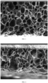
- the expandable coating is honeycomb-shaped after expansion.
- the expandable coating has a morphology substantially as shown in FIG. 1 after expansion.
- the expansion rate thickness of the coating in a free state after expansion/thickness of the expandable coating before expansion.
- the expandable coating comprises at least a water-soluble resin and a foaming agent.
- the water-soluble resin is selected from at least one of a water-soluble acrylic resin, a water-based epoxy resin, and a water-based polyurethane resin.
- the water-soluble resin is selected from a water-soluble acrylic resin.
- the solid content of the water soluble resin in the expandable coating is 30%-50%, illustratively 30%, 35%, 40%, or 50%.
- the foaming agent is thermoplastic expandable microspheres, and preferably, the thermoplastic expandable microsphere have a diameter of 5-30 ⁇ m, preferably 5-20 ⁇ m, illustratively 5 ⁇ m, 8 ⁇ m, 10 ⁇ m, 12 ⁇ m, 15 ⁇ m, 18 ⁇ m, 20 ⁇ m, 25 ⁇ m, or 30 ⁇ m.
- the area of the expandable microspheres accounts for 60%-90%, illustratively 60%, 70%, 80%, or 90% of the cross-sectional area of the expandable coating.
- the expandable microspheres in the expandable coating are expanded in a stepped manner at 110-210 °C (illustratively 110 °C, 120 °C, 130 °C, 140 °C, 150 °C, or 160 °C).
- thermoplastic expandable microspheres have an average diameter of 10-15 ⁇ m, illustratively 10 ⁇ m, 12 ⁇ m, or 15 ⁇ m.
- thermoplastic expandable microspheres have an expansion temperature of 110-210 °C, illustratively 110 °C, 120 °C, 150 °C, 160 °C, 170 °C, 180 °C, or 200 °C.
- thermoplastic expandable microspheres have a maximum heat-resistant temperature of 145-235 °C, illustratively 145 °C, 160 °C, 180 °C, 200 °C, 215 °C, or 235 °C.
- the expandable coating is prepared by coating with an expandable coating material comprising at least components of a water-soluble resin and a foaming agent.
- the water-soluble resin in the expandable coating material has a weight percentage of 45%-65%, e.g., 50%-60%.
- the foaming agent in the expandable coating material has a weight percentage of 10%-30%, e.g., 15%-25%.
- the expandable coating material further optionally comprises hectorite.
- the hectorite has a weight percentage of 0.1%-0.5%, e.g., 0.2%-0.4%.
- the expandable coating material further optionally comprises diethylene glycol butyl ether.
- the diethylene glycol butyl ether has a weight percentage of 0.5%-3%, e.g., 0.8%-2.5%.
- the expandable coating material further optionally comprises propylene glycol.
- the propylene glycol has a weight percentage of 1%-3%, e.g., 1.5%-2.5%.
- the expandable coating material further optionally comprises an acrylic thickener.
- the acrylic thickener has a weight percentage of 0.2%-0.8%, e.g., 0.3%-0.6%.
- the expandable coating material further optionally comprises a dispersant.
- the dispersant has a weight percentage of 0.1%-0.5%, e.g., 0.2%-0.4%.
- the dispersant is ethylene glycol, sodium oleate, carboxylate, or the like.
- the expandable coating further optionally comprises a leveling agent.
- the leveling agent has a weight percentage of 0.1%-0.5%, e.g., 0.2%-0.4%.
- the leveling agent is silicone oil, organosiloxane, or the like.
- the expandable coating material further comprises water.
- the sum of the weight percentages of the components in the expandable coating material is 100%.
- the preparation method for the expandable coating material comprises mixing the components described above to obtain the expandable coating material.
- the preparation method for the expandable coating material further comprises dispersing the mixed components in water to obtain a dispersion liquid. Further, the method also comprises stirring the dispersion liquid described above for homogeneous mixing.
- the expandable microspheres are sieved by a sieving machine to select expandable microspheres with the particle size range of 5-30 ⁇ m, which are mixed with a water-soluble resin and stirred for 30-60 min at normal temperature.
- the expandable coating is prepared by coating with an expandable coating material comprising the following components in percentage by weight: 45%-65% of water-soluble resin, 10%-30% of foaming agent, 0.1%-0.5% of hectorite, 0.5%-3% of diethylene glycol butyl ether, 1%-3% of propylene glycol, 0.2%-0.8% of acrylic acid thickener, 0.1%-0.5% of dispersant, and 0.1%-0.5% of leveling agent.
- an expandable coating material comprising the following components in percentage by weight: 45%-65% of water-soluble resin, 10%-30% of foaming agent, 0.1%-0.5% of hectorite, 0.5%-3% of diethylene glycol butyl ether, 1%-3% of propylene glycol, 0.2%-0.8% of acrylic acid thickener, 0.1%-0.5% of dispersant, and 0.1%-0.5% of leveling agent.
- the inventors of the present disclosure unexpectedly find that in the heating expansion process, the expansion rate needs to be controlled within the range of 300%-400%.
- the expansion rate is less than 200%, the gap between the magnet and the magnetic steel groove cannot be tightly filled; whereas if the expansion rate is more than 400%, the cross-linking inside the coating layer will be disrupted, and the thrust force is insufficient.
- the expansion rate is related to the content, the particle size, the expansion temperature, the expansion time, the coating thickness, and other conditions of the microspheres in the coating.
- the expansion rate can be controlled within an appropriate range by optimizing the amount and the expansion conditions of starting materials of all the components in the expandable coating, so as to further prepare the sintered neodymium-iron-boron magnet with excellent bonding thrust force.
- the sintered neodymium-iron-boron magnet consists of a main phase Nd 2 Fe 14 B, a Nd-rich phase, and a B-rich phase.
- the present disclosure also provides a preparation method for the expandable sintered magnet described above, which comprises coating with the expandable coating material comprising the components described above the surface of the sintered neodymium-iron-boron magnet, and performing pre-curing treatment to prepare the expandable sintered magnet.
- the sintered neodymium-iron-boron magnet further comprises a step of performing surface pretreatment before coating the expandable coating material.
- the surface pretreatment comprises processes of chemical ultrasonic degreasing, acid washing, and water washing of the surface of the sintered neodymium-iron-boron magnet.
- the degreasing liquid used in the degreasing process is a composite solution of a base and a surfactant.
- the base is sodium hydroxide or sodium carbonate at a concentration of 10-20 g/L, illustratively 10 g/L, 15 g/L, or 20 g/L.
- the surfactant is sodium dodecyl sulfonate or sodium dodecyl sulfate at a concentration of 2-6 g/L, illustratively 2 g/L, 3 g/L, 4 g/L, 5 g/L, or 6 g/L.
- the degreasing liquid has a temperature of 30-70 °C, illustratively 30 °C, 40 °C, 50 °C, 60 °C, or 70 °C. Further, the degreasing is performed for 1-20 min, illustratively 1 min, 5 min, 10 min, 15 min, or 20 min.
- the acid used for acid washing can be an aqueous nitric acid or citric acid solution.
- the acid used for acid washing is at a concentration of 5-30 wt%, illustratively 5 wt%, 10 wt%, 15 wt%, 20 wt%, 25 wt%, or 30 wt%.
- the acid washing is performed for 5-30 s, illustratively 5 s, 10 s, 15 s, 20 s, 25 s, or 30 s.
- the water washing includes ultrasonic water washing using pure water. Further, the washing is performed for 20-120 s, illustratively 20 s, 30 s, 50 s, 80 s, 100 s, or 120 s.
- the coating method includes, but is not limited to, spray coating, printing, dipping, applying, and the like.
- the coating method is spray coating.
- the coating has a thickness of 50-300 ⁇ m, preferably 80-150 ⁇ m, illustratively 50 ⁇ m, 80 ⁇ m, 110 ⁇ m, 150 ⁇ m, 180 ⁇ m, 200 ⁇ m, 250 ⁇ m, or 300 ⁇ m.
- the inventors of the present disclosure unexpectedly find that the expandable coating with too small coating thickness will result in insufficient expansion force in the assembly process, so that the predetermined thrust force requirements cannot be met.
- the coating thickness of the expandable coating is too large, the surface of the coating is liable to peel off and crack.
- the coating thickness of the expandable coating is related to the reserved size in the magnetic steel groove, and the larger the reserved size is, the thicker the required coating thickness is.
- the inventors of the present disclosure unexpectedly find that after the coating expands, the coating exhibits the best effect when the compression rate of expansion of the coating in the magnetic steel groove is 35-65%, and at this time, the bonding force between the magnet and the magnetic steel groove is best, and the magnet has maximum thrust force in the magnetic steel groove.
- Compression rate of expansion m (H 1 -H 0 )/(H 2 -H 0 ); wherein: H 0 is the coating thickness of the expandable coating, H 1 is the thickness of the expandable coating after expansion in the magnetic steel groove, and H 2 is the thickness of the expandable coating after expansion in the natural state.
- the pre-curing treatment involves natural drying of the coating under normal temperature conditions (15-35 °C) or under medium-low temperature (35-90 °C) baking conditions to form a complete coating.
- the present disclosure also provides application of the expandable sintered neodymium-iron-boron magnet described above in a motor rotor.
- the present disclosure also provides a motor rotor workpiece which comprises the expandable sintered neodymium-iron-boron magnet described above.
- the present disclosure also provides an assembly method of the motor rotor workpiece described above, which comprises assembling the expandable sintered neodymium-iron-boron magnet described above into a magnetic steel groove, and performing heating expansion treatment to prepare the motor rotor workpiece.
- the inventors of the present disclosure unexpectedly find that the final performance of the expandable coating are related to the expansion temperature, the heating rate, and the holding time in the expansion assembly process, wherein the expansion temperature has a direct effect on the structure of the final expandable coating.
- the heating expansion treatment is performed by a two-stage heating method.
- the first expansion stage has an expansion temperature of 110-160 °C, illustratively 110 °C, 120 °C, 130 °C, 140 °C, 150 °C, or 160 °C. Further, the first expansion stage is at a heating rate of 5-15 °C/min, illustratively 5 °C/min, 10 °C/min, or 15 °C/min.
- the expansion temperature of the first expansion stage When the expansion temperature of the first expansion stage is lower than 110 °C, a large number of microspheres will fail to expand and cannot reach the required expansion rate; however, when the expansion temperature of the first expansion stage is higher than 160 °C, the microspheres will expand rapidly, but due to different particle sizes of the microspheres in the coating, the microspheres with small particle sizes will expand rapidly and rupture, so that the coating collapses in advance, and thus the corresponding supporting force cannot be obtained.
- the heating rate of the first expansion stage is controlled to be 5-15 °C/min, the expandable coating can be uniformly expanded, and liquefied hydrocarbon gas in the expandable microspheres is fully gasified in the heating process, so that the coating is slowly and uniformly expanded.
- the second expansion stage of the heat expansion treatment has an expansion temperature of 180-210 °C, illustratively 180 °C, 190 °C, 200 °C, or 210 °C. Further, the second expansion stage is at a heating rate of 30-60 °C/min, illustratively 30 °C/min, 40 °C/min, 50 °C/min, or 60 °C/min. After the coating is uniformly expanded, heating is performed at an accelerated rate, so that the thermoplastic resin in the coating is quickly cured.
- thermoplastic expandable microsphere of the present disclosure comprises a thermoplastic resin shell and a propellant encapsulated therein, wherein more than 70% of the propellant is composed of isooctane.
- the propellant can be selected from the group consisting of butane, pentane, heptane, and other liquids within an appropriate boiling point range.
- the propellant evaporates to raise the internal pressure of the microspheres to cause the volume change of the propellant, so that the shell which becomes soft after being heated deforms and expands, and softens at the same time, thereby causing the limited expansion of the microspheres.
- the temperature at which expansion starts is Tstar and the temperature at which the maximum degree of expansion is reached is Tmax. When the temperature exceeds Tmax, the propellant is released through the thermoplastic resin shell to such an extent that the microspheres start to rupture.
- the high-boiling-point solvent in the coating volatilizes to dissolve the shell of expandable microspheres with a particle size ⁇ 10 ⁇ m and a wall thickness ⁇ 3 ⁇ m, so that the wall of the shell becomes thinner and the microspheres rupture before the maximum expansion temperature is reached. More than 60% of the microspheres in the expandable coating rupture. After the rupture of the microspheres, the propellant in the microspheres is released. The microspheres do not accelerate to expand any more so as to form a hole structure, and the thermoplastic resin on the outer wall of the microspheres is cross-linked with the water-soluble resin in the coating to form a network structure so as to increase the bonding force of the magnet in the magnetic steel groove.
- the expandable microspheres with a particle size > 10 ⁇ m in the coating continues to expand, but the high-boiling-point solvent in the coating has volatilized and cannot accelerate the rupture of the shells of the expandable microspheres.
- the maximum expansion temperature of the second expansion stage is lower than the maximum expansion temperature of microspheres with a particle size > 10 ⁇ m, and the release of the propellant is slowed down.
- the releasing agent in the expandable microspheres consists of more than 70% of isooctane, so that the expansion rate of the coating can be controlled by detecting the release amount of the isooctane in the expansion process, and more than 60% of microspheres in the coating are controlled to rupture, and then the microspheres are cross-linked with the water-soluble resin to form a network structure.
- the present disclosure can determine the gas release amount of isooctane in the expansion process by detecting the collected gas, thereby controlling the rupture proportion of the expandable microspheres.
- the detection method comprises: taking a magnet (the specification is 35.5 mm ⁇ 16.5 mm ⁇ 5.5 mm) coated with an expandable coating, placing the magnet in a sealed sampling bottle, heating the magnet at the same heating temperature and heating rate as the expansion process conditions in the expansion assembly process, naturally cooling the magnet to 60 °C after heating, purging gas in the sampling bottle into a GC column for detection by using nitrogen, and recording the content w 1 of isooctane at this time; continuously heating the magnet in the sampling bottle at a temperature (240 °C) higher than the maximum expansion temperature T max of the expandable microspheres for 3 h to thoroughly rupture the microspheres in the expandable coating and thoroughly release the isooctane in the microspheres, and recording the content w 2 of the isooctane at this time.
- the rupture proportion of the microspheres q w 1 /(w 1 + w 2 ) is calculated from the released amount of isooctane.
- the inventors unexpectedly find through a large number of experiments that: when the rupture proportion q of the microspheres is within the range of 60-85%, the expandable coating has excellent supporting effect, the expandable magnet has relatively high thrust force in the use environment, and the coating has the best bonding effect.
- the expandable coating first undergoes softening process.
- the expandable microspheres in the coating increase in volume due to heating, and the overall thickness of the expandable coating increases, resulting in extrusion force on the inner wall of the motor tooling. Meanwhile, the hot melt resin in the expandable coating will produce a certain bonding force after softening to fix the sintered magnet in the motor tooling, thus completing the assembly process.
- a sintered neodymium-iron-boron magnet (not magnetized) with the specification of 35.5 mm ⁇ 16.5 mm ⁇ 5.5 mm was used, and a magnetic steel groove with the assembled motor rotor had a size of 36 mm ⁇ 17 mm ⁇ 6 mm.
- the sintered neodymium-iron-boron magnet was degreased at 60 °C for 2 min by using a composite degreasing liquid with sodium hydroxide at a concentration of 15 g/L and sodium dodecyl sulfonate at a concentration of 3 g/L, and then subjected to acid washing for 15 s by using 25 wt% of an aqueous citric acid solution, and finally placed in deionized water for ultrasonic cleaning for 2 min.
- Expandable coating preparation the expandable coating material was formulated according to the following components (in percentage by weight): 55% of water-soluble acrylic resin, 30% of water, 10% of foaming agent, 0.2% of hectorite, 1.5% of diethylene glycol butyl ether, 2% of propylene glycol, 0.5% of acrylic acid thickener, 0.4% of ethylene glycol, and 0.4% of polydimethylsiloxane, wherein the foaming agent was selected from thermoplastic expandable microspheres with an average particle size of 13 ⁇ m.
- Coating treatment the expandable coating material described above was coated on the surface of the magnet by compressed air spray coating, wherein the spray coating speed was 120 mm/s, the coating thickness was 110 ⁇ m, the distance between a nozzle and a workpiece was 15 cm, the angle between a spray gun and the workpiece was 25°, and the argon pressure of the spray gun was 0.6 MPa.
- Pre-curing treatment the surface of the magnet coated with the expandable coating material was heated to 50 °C, and subjected to a pre-curing treatment to obtain a coating with a thickness of 110 ⁇ m.
- Coating expansion the magnet coated with the expandable coating was placed into a high-temperature oven under a non-pressure state, and subjected to two-stage heating, that is, the magnet was first heated to 120 °C and maintained at this temperature for 5 min, and then quickly heated to 170 °C and maintained at this temperature for 3 min.
- the first heating stage was at a heating rate of 5 °C/min
- the second heating stage was at a heating stage of 50 °C/min.
- the resin within the expandable coating softens, and the thickness of the expandable coating increases with the increase of the volume of the expandable microspheres.
- FIG. 1 it can be seen that the microspheres expand uniformly, and the walls of the microspheres and the resin are cross-linked with each other to form a stable supporting structure.
- the expandable coating consists of a water-soluble acrylic resin and expandable microspheres.
- the thickness of the expandable coating was increased from 110 ⁇ m to 394 ⁇ m after the pre-curing treatment, with an expansion rate of 358%. After expansion, the expandable coating is honeycomb-shaped, and the cross-sectional area of the expandable microspheres accounts for 82% of that of the expandable coating.
- the proportion of the cross-sectional area of the expandable microspheres to the cross-sectional area of the expandable coating in a cross section is calculated as follows: firstly, taking a scanning electron microscope photo of the cross-section of the expandable coating, then identifying gaps in the cross section through the image, calculating the sum of the areas of the gaps, and taking the areas of the gaps as the proportion of the cross section of the expandable microspheres to the cross section of the expandable coating).
- the magnet coated with the expandable coating was assembled into a magnetic steel groove of a motor rotor, placed into a high-temperature oven, and subjected to two-stage heating, that is, the magnet was first heated to 120 °C and maintained at this temperature for 5 min, and then quickly heated to 170 °C and maintained at this temperature for 3 min.
- the first heating stage was at a heating rate of 5 °C/min
- the second heating stage was at a heating stage of 50 °C/min.
- the expandable coating extrudes the inner wall of the magnetic steel groove after being heated to expand, and the gap between the magnetic steel groove and the magnet is filled, and meanwhile, the resin in the coating is cross-linked with the expandable microspheres to form a honeycomb-shaped coating structure. Due to the limitation of the inner wall of the magnetic steel groove, the coating cannot expand to the maximum in the expansion process, so that the expanded honeycomb-shaped structure is compressed and wrinkled.) After the heating, the motor rotor was cooled under natural conditions. The volume of the expandable microspheres increased due to the change of ambient temperature, and the change was irreversible. Due to the increase in the volume of the coating, the gap between the magnet and the inner wall of the magnetic steel groove was filled, so that the magnet was tightly fixed in the magnetic steel. At this time, the magnet product obtained was named sample 1.
- the bonding thrust force at room temperature (25 °C) was 1200 N/cm 2
- the bonding thrust force at high temperature (170 °C) was 530 N/cm 2 .
- the surface pretreatment method, the expandable coating material, and the coating process were the same as those in Example 1.
- a magnet with an expandable coating with a thickness of 110 ⁇ m was inserted into a magnetic steel groove, and different first expansion temperature, second expansion temperature, heating rate, and expansion time were used to obtain the optimal assembly process conditions.
- the results are shown in Table 1 below.
- the rupture proportion of the microspheres was deduced by determining the release amount of isooctane, and it could be found that when the ruptured microspheres were cross-linked with the resin coating in the case of the rupture proportion in the range of 60%-85%, the obtained coating has a stable structure and can stably support the gap between the magnet and the magnetic steel groove.
- FIG. 1 shows the state of the coating after the expansion of sample 1, from which it can be seen that: the microspheres expand uniformly to cross-link with the walls of the microspheres and the resin, thereby forming a stable support structure.
- FIG. 2 shows the state of the coating after the expansion of sample 5, from which it can be seen that there are many ruptured microspheres, and the microspheres are fused and adhered to each other to form relatively large voids, so that the coating has lower bonding force in a high-temperature state.
- a sintered neodymium-iron-boron magnet (not magnetized) with the specification of 35.5 mm ⁇ 16.5 mm ⁇ 5.5 mm was used, and a magnetic steel groove with the assembled motor rotor had a size of 36 mm ⁇ 17 mm ⁇ 6 mm.
- the surface pretreatment method same as that in Example 1 was used.
- the sintered neodymium-iron-boron magnet was degreased at 60 °C for 2 min by using a composite degreasing liquid with sodium hydroxide at a concentration of 15 g/L and sodium dodecyl sulfonate at a concentration of 3 g/L, and then subjected to acid washing for 15 s by using 25 wt% of an aqueous citric acid solution, and finally placed in deionized water for ultrasonic cleaning for 2 min.
- the expandable powder coating material produced by AKZO-Nobel company was selected.
- the coating consists of 50% of epoxy resin powder, 20% of curing agent, 10% of elastomer resin, and 20% of thermoplastic expandable microspheres.
- the expandable coating material described above was coated on the surface of the magnet by compressed air spray coating, wherein the spray coating speed was 60 mm/s, the coating thickness was 110 ⁇ m, the distance between a nozzle and a workpiece was 10 cm, the angle between a spray gun and the workpiece was 25°, and the argon pressure of the spray gun was 0.6 MPa.
- the magnet coated with the expandable coating was assembled into a magnetic steel groove of a motor rotor, placed into a high-temperature oven, and heated at 190 °C for 20 min.
- the volume of the thermoplastic expandable microspheres was increased due to temperature change, resulting in the expansion of the overall coating.
- the epoxy resin was cured, making the coating stable and non-retractable.
- the cross-sectional structure of the expandable coating was observed using an electron microscope. As shown in FIG. 3 , the thickness of the expandable coating was increased from 110 ⁇ m to 180 ⁇ m after the pre-curing treatment, with the expansion rate reaching 163%. After expansion, the edges of the thermoplastic expandable microspheres can be clearly seen.
- the expandable microspheres under heating conditions, increased in microsphere volume solely due to the vaporization of the liquid alkane within the microspheres. Whether the microspheres in the coating are ruptured is speculated by determining the released amount of isooctane in the expandable microspheres.
- the released amount w1 of isooctane is determined to be 1.52 mg/L.
- the expandable microspheres in the coating are completely ruptured, and the released amount w2 of isooctane is 5.34 mg/L.
- the cross-sectional area of the expandable microspheres accounts for 35% of that of the expandable coating.
- the normal-temperature bonding thrust force and the high-temperature bonding thrust force of the magnet were determined.
- the normal-temperature (25 °C) bonding thrust force was 920 N/cm 2
- the high-temperature (170 °C) bonding thrust force was 310 N/cm 2 .
- a sintered neodymium-iron-boron magnet (not magnetized) with the specification of 35.5 mm ⁇ 16.5 mm ⁇ 5.5 mm was used, and a magnetic steel groove with the assembled motor rotor had a size of 36 mm ⁇ 17 mm ⁇ 6 mm.
- the surface pretreatment process and expandable coating material same as those in Example 1 were used.
- the expandable coating described above was coated on the surface of the magnet by compressed air spray coating, wherein the thicknesses for the spray coating were 80 ⁇ m, 90 ⁇ m, 100 ⁇ m, 110 ⁇ m, 120 ⁇ m, 130 ⁇ m, 140 ⁇ m, and 150 ⁇ m, respectively.
- the magnet coated with the expandable coating was assembled into a magnetic steel groove of a motor rotor, placed into a high-temperature oven, and subjected to two-stage heating, that is, the magnet was first heated to 120 °C and maintained at this temperature for 5 min, and then quickly heated to 170 °C and maintained at this temperature for 3 min.
- the first heating stage was at a heating rate of 5 °C/min
- the second heating stage was at a heating stage of 50 °C/min.
- the normal-temperature thrust force and the high-temperature thrust force of the magnet in the operating state were determined.
- FIG. 4 shows the coating state of sample 10 in the magnetic steel groove.
- the expandable coating is compressed and wrinkled due to the limitation of the inner wall of the magnetic steel groove.
- the contact surface of the expandable coating and the contact surface of the inner wall of the magnetic steel groove generate relatively strong stress.
- the stress on the unit area of the coating is increased, and the internal defects of the coating are exponentially increased, so that the cohesive strength of an adhesive layer is reduced. Therefore, by controlling the compression rate to be above 35%, the magnet with better normal-temperature thrust force and high-temperature thrust force can be prepared.
- the inventors find through a large number of experiments that: when the compression rate is greater than 65%, the coating is more sensitive to the shrinkage stress and thermal stress caused by temperature change, which will result in the loss of cohesive strength of the magnet, thereby reducing normal-temperature thrust force and high-temperature thrust force of the magnet.
Landscapes
- Engineering & Computer Science (AREA)
- Power Engineering (AREA)
- Chemical & Material Sciences (AREA)
- Crystallography & Structural Chemistry (AREA)
- Inorganic Chemistry (AREA)
- Manufacturing & Machinery (AREA)
- Mechanical Engineering (AREA)
- Materials Engineering (AREA)
- Organic Chemistry (AREA)
- Metallurgy (AREA)
- Physics & Mathematics (AREA)
- Electromagnetism (AREA)
- Environmental & Geological Engineering (AREA)
- Hard Magnetic Materials (AREA)
- Other Surface Treatments For Metallic Materials (AREA)
- Manufacturing Cores, Coils, And Magnets (AREA)
- Laminated Bodies (AREA)
- Powder Metallurgy (AREA)
- Paints Or Removers (AREA)
Applications Claiming Priority (2)
| Application Number | Priority Date | Filing Date | Title |
|---|---|---|---|
| CN202110657206.1A CN113764150B (zh) | 2021-06-11 | 2021-06-11 | 一种可膨胀烧结钕铁硼磁体及其制备方法和应用 |
| PCT/CN2022/098424 WO2022258069A1 (zh) | 2021-06-11 | 2022-06-13 | 一种可膨胀烧结钕铁硼磁体及其制备方法和应用 |
Publications (4)
| Publication Number | Publication Date |
|---|---|
| EP4336522A1 true EP4336522A1 (de) | 2024-03-13 |
| EP4336522A4 EP4336522A4 (de) | 2024-11-06 |
| EP4336522C0 EP4336522C0 (de) | 2025-10-08 |
| EP4336522B1 EP4336522B1 (de) | 2025-10-08 |
Family
ID=78787448
Family Applications (1)
| Application Number | Title | Priority Date | Filing Date |
|---|---|---|---|
| EP22819665.5A Active EP4336522B1 (de) | 2021-06-11 | 2022-06-13 | Expandierbarer gesinterter neodym-eisen-bor-magnet, herstellungsverfahren dafür und anwendung davon |
Country Status (6)
| Country | Link |
|---|---|
| US (1) | US20240274332A1 (de) |
| EP (1) | EP4336522B1 (de) |
| JP (1) | JP7703053B2 (de) |
| KR (1) | KR102755970B1 (de) |
| CN (1) | CN113764150B (de) |
| WO (1) | WO2022258069A1 (de) |
Families Citing this family (5)
| Publication number | Priority date | Publication date | Assignee | Title |
|---|---|---|---|---|
| CN113764150B (zh) * | 2021-06-11 | 2023-01-10 | 烟台正海磁性材料股份有限公司 | 一种可膨胀烧结钕铁硼磁体及其制备方法和应用 |
| CN114574013A (zh) * | 2022-05-06 | 2022-06-03 | 天津三环乐喜新材料有限公司 | 一种高附着力磁体无机膨胀涂层 |
| CN115572558A (zh) * | 2022-09-07 | 2023-01-06 | 安徽大地熊新材料股份有限公司 | 环境友好型磁体固定材料及其制备方法和应用 |
| CN117820937B (zh) * | 2022-09-27 | 2026-01-16 | 烟台正海磁性材料股份有限公司 | 一种膨胀涂层及其制备方法和应用、包含该膨胀涂层的永磁体 |
| CN116936214B (zh) * | 2023-09-15 | 2024-01-16 | 广东尚朋电磁科技有限公司 | 一种宽频域软磁铁氧体磁性元件、生产工艺及生产设备 |
Family Cites Families (17)
| Publication number | Priority date | Publication date | Assignee | Title |
|---|---|---|---|---|
| US4935080A (en) * | 1988-01-29 | 1990-06-19 | Kollmorgen Corporation | Protection and bonding of neodymium-boron-iron magnets used in the formation of magnet assemblies |
| WO2009091987A2 (en) * | 2008-01-18 | 2009-07-23 | Wild River Consulting Group, Llc | Melt molding polymer composite and method of making and using the same |
| DE102009028180A1 (de) * | 2009-08-03 | 2011-02-10 | Henkel Ag & Co. Kgaa | Verfahren zum Befestigen eines Magneten auf oder in einem Rotor oder Stator |
| JP2014096480A (ja) * | 2012-11-09 | 2014-05-22 | Tanaka Seimitsu Kogyo Kk | 磁性強化樹脂 |
| KR102090921B1 (ko) * | 2013-06-11 | 2020-03-19 | 현대모비스 주식회사 | 자동차 부품 질감 도료용 조성물 및 이를 포함하는 자동차 부품 |
| JP5972249B2 (ja) * | 2013-11-27 | 2016-08-17 | 三菱電機株式会社 | 磁石埋込型回転子 |
| DE102014214381A1 (de) * | 2014-07-23 | 2016-01-28 | Volkswagen Aktiengesellschaft | Pulverlack, Verwendung desselben und Verfahren zur Herstellung von Rotoren für permanentmagneterregte E-Maschinen |
| KR102229282B1 (ko) * | 2015-11-09 | 2021-03-18 | 현대모비스 주식회사 | 희토류 소결자석의 표면 처리방법 |
| US10658892B2 (en) * | 2016-03-31 | 2020-05-19 | Aisin Aw Co., Ltd. | Rotor for rotating electrical machine |
| DE102016206121A1 (de) * | 2016-04-13 | 2017-10-19 | Volkswagen Aktiengesellschaft | Verfahren zur Herstellung eines für eine elektrische Maschine vorgesehenen Kühlmantels und Kühlmantel für eine elektrische Maschine |
| CN107134362B (zh) * | 2017-06-12 | 2019-04-16 | 佛山市川东磁电股份有限公司 | 一种钕铁硼磁铁包覆结构及方法 |
| CN108047480B (zh) * | 2017-12-05 | 2020-11-27 | 山东瑞丰高分子材料股份有限公司 | 高温膨胀聚合物微球及其制备方法 |
| CN108015293B (zh) * | 2017-12-21 | 2021-04-13 | 宁波金轮磁材技术有限公司 | 一种双合金钕铁硼稀土永磁体及其制造方法 |
| EP3819922B1 (de) * | 2019-11-07 | 2024-09-11 | Volkswagen AG | Verfahren zur beschichten eines magneten für einen rotor |
| CN113388306B (zh) * | 2021-04-02 | 2022-08-16 | 烟台高氏化工科技有限公司 | 一种涂料组合物及其制备方法和应用 |
| CN113150366B (zh) * | 2021-04-02 | 2022-12-09 | 烟台高氏化工科技有限公司 | 一种可加热膨胀微球的组合物及其应用 |
| CN113764150B (zh) * | 2021-06-11 | 2023-01-10 | 烟台正海磁性材料股份有限公司 | 一种可膨胀烧结钕铁硼磁体及其制备方法和应用 |
-
2021
- 2021-06-11 CN CN202110657206.1A patent/CN113764150B/zh active Active
-
2022
- 2022-06-13 KR KR1020237041585A patent/KR102755970B1/ko active Active
- 2022-06-13 EP EP22819665.5A patent/EP4336522B1/de active Active
- 2022-06-13 JP JP2023576226A patent/JP7703053B2/ja active Active
- 2022-06-13 US US18/568,830 patent/US20240274332A1/en active Pending
- 2022-06-13 WO PCT/CN2022/098424 patent/WO2022258069A1/zh not_active Ceased
Also Published As
| Publication number | Publication date |
|---|---|
| WO2022258069A1 (zh) | 2022-12-15 |
| EP4336522C0 (de) | 2025-10-08 |
| KR20240004870A (ko) | 2024-01-11 |
| JP2024527250A (ja) | 2024-07-24 |
| EP4336522B1 (de) | 2025-10-08 |
| US20240274332A1 (en) | 2024-08-15 |
| JP7703053B2 (ja) | 2025-07-04 |
| EP4336522A4 (de) | 2024-11-06 |
| CN113764150A (zh) | 2021-12-07 |
| KR102755970B1 (ko) | 2025-01-15 |
| CN113764150B (zh) | 2023-01-10 |
Similar Documents
| Publication | Publication Date | Title |
|---|---|---|
| EP4336522A1 (de) | Expandierbarer gesinterter neodym-eisen-bor-magnet, herstellungsverfahren dafür und anwendung davon | |
| EP4317278A1 (de) | Zusammensetzung aus wärmeexpandierbaren mikrokugeln und ihre verwendung | |
| JP3956760B2 (ja) | フレキシブル磁石の製造方法とその永久磁石型モ−タ | |
| EP1818955A1 (de) | Permanentmagnet für einen motor, motorgehäuse und motoreinrichtung | |
| EP3828904A1 (de) | Verfahren zur verbesserung der koerzivität eines bogenförmigen nd-fe-b-magneten | |
| JP2022044560A (ja) | Nd-Fe-B系永久磁性体表面へのセラミック前駆体溶液吹き付け装置、及びNd-Fe-B系永久磁性体表面へのセラミック層形成方法。 | |
| EP4345139A1 (de) | Expandierte beschichtung, herstellungsverfahren und verwendung davon sowie permanentmagnet damit | |
| CN112038080B (zh) | R-t-b系永久磁体的制造方法 | |
| CN113453526A (zh) | 一种低压缩应力电磁屏蔽材料及其制备方法 | |
| US20220356378A1 (en) | Method of Preparing Elastic Pressure-Sensitive Adhesive Tape and Elastic Pressure-Sensitive Adhesive Tape | |
| Huang et al. | A highly reliable die bonding approach for high power devices by low temperature pressureless sintering using a novel Cu nanoparticle paste | |
| CN118919277A (zh) | 一种绝缘包覆型软磁粉体及其制备方法和应用 | |
| CN106783768A (zh) | 一种预成型纳米银膜 | |
| JPWO2022258069A5 (de) | ||
| CN108122655B (zh) | 一种烧结NdFeB磁体及其制备方法 | |
| CN113881258B (zh) | 一种铝合金隔热耐冲刷复合涂层及其制备方法 | |
| CN115815587B (zh) | 一种叠层片式电感内电极银浆用改性银粉及其制备方法 | |
| CN111696742A (zh) | 一种无重稀土高性能钕铁硼永磁材料及其制备方法 | |
| WO1999023676A1 (fr) | Procede de fabrication d'aimants a liaison r-fe-b presentant une haute resistance a la corrosion | |
| CN110517882B (zh) | 一种钕铁硼表面渗铽方法 | |
| KR20230172100A (ko) | 희토류 영구자석의 제조 방법 및 이에 의해 제조된 희토류 영구자석 | |
| CN117565301A (zh) | 一种提升聚三氟氯乙烯和铝合金复合结构界面性能的制备方法 | |
| JPWO2006022101A1 (ja) | 自己組織化した網目状境界相を有する異方性希土類ボンド磁石とそれを用いた永久磁石型モータ | |
| JP2023137382A (ja) | 物品、物品の製造方法、発泡性接着シートおよび接着剤組成物 | |
| CN113394015B (zh) | 一种大深度晶界扩散的钕铁硼磁体的制备方法 |
Legal Events
| Date | Code | Title | Description |
|---|---|---|---|
| STAA | Information on the status of an ep patent application or granted ep patent |
Free format text: STATUS: THE INTERNATIONAL PUBLICATION HAS BEEN MADE |
|
| PUAI | Public reference made under article 153(3) epc to a published international application that has entered the european phase |
Free format text: ORIGINAL CODE: 0009012 |
|
| STAA | Information on the status of an ep patent application or granted ep patent |
Free format text: STATUS: REQUEST FOR EXAMINATION WAS MADE |
|
| 17P | Request for examination filed |
Effective date: 20231208 |
|
| AK | Designated contracting states |
Kind code of ref document: A1 Designated state(s): AL AT BE BG CH CY CZ DE DK EE ES FI FR GB GR HR HU IE IS IT LI LT LU LV MC MK MT NL NO PL PT RO RS SE SI SK SM TR |
|
| DAV | Request for validation of the european patent (deleted) | ||
| DAX | Request for extension of the european patent (deleted) | ||
| REG | Reference to a national code |
Ref country code: DE Ref legal event code: R079 Free format text: PREVIOUS MAIN CLASS: H01F0001057000 Ipc: H01F0041020000 Ref country code: DE Ref legal event code: R079 Ref document number: 602022022807 Country of ref document: DE Free format text: PREVIOUS MAIN CLASS: H01F0001057000 Ipc: H01F0041020000 |
|
| STAA | Information on the status of an ep patent application or granted ep patent |
Free format text: STATUS: EXAMINATION IS IN PROGRESS |
|
| A4 | Supplementary search report drawn up and despatched |
Effective date: 20241008 |
|
| RIC1 | Information provided on ipc code assigned before grant |
Ipc: C09D 163/00 20060101ALI20241001BHEP Ipc: H01F 7/02 20060101ALI20241001BHEP Ipc: H01F 1/057 20060101ALI20241001BHEP Ipc: H01F 41/02 20060101AFI20241001BHEP |
|
| 17Q | First examination report despatched |
Effective date: 20241018 |
|
| GRAP | Despatch of communication of intention to grant a patent |
Free format text: ORIGINAL CODE: EPIDOSNIGR1 |
|
| STAA | Information on the status of an ep patent application or granted ep patent |
Free format text: STATUS: GRANT OF PATENT IS INTENDED |
|
| INTG | Intention to grant announced |
Effective date: 20250520 |
|
| GRAS | Grant fee paid |
Free format text: ORIGINAL CODE: EPIDOSNIGR3 |
|
| GRAA | (expected) grant |
Free format text: ORIGINAL CODE: 0009210 |
|
| STAA | Information on the status of an ep patent application or granted ep patent |
Free format text: STATUS: THE PATENT HAS BEEN GRANTED |
|
| AK | Designated contracting states |
Kind code of ref document: B1 Designated state(s): AL AT BE BG CH CY CZ DE DK EE ES FI FR GB GR HR HU IE IS IT LI LT LU LV MC MK MT NL NO PL PT RO RS SE SI SK SM TR |
|
| REG | Reference to a national code |
Ref country code: GB Ref legal event code: FG4D Ref country code: CH Ref legal event code: F10 Free format text: ST27 STATUS EVENT CODE: U-0-0-F10-F00 (AS PROVIDED BY THE NATIONAL OFFICE) Effective date: 20251008 |
|
| REG | Reference to a national code |
Ref country code: DE Ref legal event code: R096 Ref document number: 602022022807 Country of ref document: DE |
|
| REG | Reference to a national code |
Ref country code: IE Ref legal event code: FG4D |
|
| U01 | Request for unitary effect filed |
Effective date: 20251027 |
|
| U07 | Unitary effect registered |
Designated state(s): AT BE BG DE DK EE FI FR IT LT LU LV MT NL PT RO SE SI Effective date: 20251031 |