EP4335828B1 - Herstellen von wasserstoff und lithiumhydroxid im basischen milieu - Google Patents
Herstellen von wasserstoff und lithiumhydroxid im basischen milieu Download PDFInfo
- Publication number
- EP4335828B1 EP4335828B1 EP22195067.8A EP22195067A EP4335828B1 EP 4335828 B1 EP4335828 B1 EP 4335828B1 EP 22195067 A EP22195067 A EP 22195067A EP 4335828 B1 EP4335828 B1 EP 4335828B1
- Authority
- EP
- European Patent Office
- Prior art keywords
- process according
- working medium
- compartment
- membrane
- lithium hydroxide
- Prior art date
- Legal status (The legal status is an assumption and is not a legal conclusion. Google has not performed a legal analysis and makes no representation as to the accuracy of the status listed.)
- Active
Links
Images


Classifications
-
- C—CHEMISTRY; METALLURGY
- C02—TREATMENT OF WATER, WASTE WATER, SEWAGE, OR SLUDGE
- C02F—TREATMENT OF WATER, WASTE WATER, SEWAGE, OR SLUDGE
- C02F1/00—Treatment of water, waste water, or sewage
- C02F1/46—Treatment of water, waste water, or sewage by electrochemical methods
- C02F1/461—Treatment of water, waste water, or sewage by electrochemical methods by electrolysis
- C02F1/46104—Devices therefor; Their operating or servicing
- C02F1/4618—Devices therefor; Their operating or servicing for producing "ionised" acidic or basic water
-
- C—CHEMISTRY; METALLURGY
- C25—ELECTROLYTIC OR ELECTROPHORETIC PROCESSES; APPARATUS THEREFOR
- C25B—ELECTROLYTIC OR ELECTROPHORETIC PROCESSES FOR THE PRODUCTION OF COMPOUNDS OR NON-METALS; APPARATUS THEREFOR
- C25B1/00—Electrolytic production of inorganic compounds or non-metals
- C25B1/01—Products
- C25B1/34—Simultaneous production of alkali metal hydroxides and chlorine, oxyacids or salts of chlorine, e.g. by chlor-alkali electrolysis
- C25B1/46—Simultaneous production of alkali metal hydroxides and chlorine, oxyacids or salts of chlorine, e.g. by chlor-alkali electrolysis in diaphragm cells
-
- B—PERFORMING OPERATIONS; TRANSPORTING
- B01—PHYSICAL OR CHEMICAL PROCESSES OR APPARATUS IN GENERAL
- B01D—SEPARATION
- B01D61/00—Processes of separation using semi-permeable membranes, e.g. dialysis, osmosis or ultrafiltration; Apparatus, accessories or auxiliary operations specially adapted therefor
- B01D61/42—Electrodialysis; Electro-osmosis ; Electro-ultrafiltration; Membrane capacitive deionization
- B01D61/422—Electrodialysis
-
- B—PERFORMING OPERATIONS; TRANSPORTING
- B01—PHYSICAL OR CHEMICAL PROCESSES OR APPARATUS IN GENERAL
- B01D—SEPARATION
- B01D69/00—Semi-permeable membranes for separation processes or apparatus characterised by their form, structure or properties; Manufacturing processes specially adapted therefor
- B01D69/06—Flat membranes
-
- B—PERFORMING OPERATIONS; TRANSPORTING
- B01—PHYSICAL OR CHEMICAL PROCESSES OR APPARATUS IN GENERAL
- B01D—SEPARATION
- B01D71/00—Semi-permeable membranes for separation processes or apparatus characterised by the material; Manufacturing processes specially adapted therefor
- B01D71/02—Inorganic material
-
- C—CHEMISTRY; METALLURGY
- C01—INORGANIC CHEMISTRY
- C01D—COMPOUNDS OF ALKALI METALS, i.e. LITHIUM, SODIUM, POTASSIUM, RUBIDIUM, CAESIUM, OR FRANCIUM
- C01D15/00—Lithium compounds
- C01D15/02—Oxides; Hydroxides
-
- C—CHEMISTRY; METALLURGY
- C01—INORGANIC CHEMISTRY
- C01D—COMPOUNDS OF ALKALI METALS, i.e. LITHIUM, SODIUM, POTASSIUM, RUBIDIUM, CAESIUM, OR FRANCIUM
- C01D15/00—Lithium compounds
- C01D15/08—Carbonates; Bicarbonates
-
- C—CHEMISTRY; METALLURGY
- C02—TREATMENT OF WATER, WASTE WATER, SEWAGE, OR SLUDGE
- C02F—TREATMENT OF WATER, WASTE WATER, SEWAGE, OR SLUDGE
- C02F1/00—Treatment of water, waste water, or sewage
- C02F1/38—Treatment of water, waste water, or sewage by centrifugal separation
-
- C—CHEMISTRY; METALLURGY
- C02—TREATMENT OF WATER, WASTE WATER, SEWAGE, OR SLUDGE
- C02F—TREATMENT OF WATER, WASTE WATER, SEWAGE, OR SLUDGE
- C02F1/00—Treatment of water, waste water, or sewage
- C02F1/44—Treatment of water, waste water, or sewage by dialysis, osmosis or reverse osmosis
- C02F1/444—Treatment of water, waste water, or sewage by dialysis, osmosis or reverse osmosis by ultrafiltration or microfiltration
-
- C—CHEMISTRY; METALLURGY
- C02—TREATMENT OF WATER, WASTE WATER, SEWAGE, OR SLUDGE
- C02F—TREATMENT OF WATER, WASTE WATER, SEWAGE, OR SLUDGE
- C02F1/00—Treatment of water, waste water, or sewage
- C02F1/46—Treatment of water, waste water, or sewage by electrochemical methods
- C02F1/461—Treatment of water, waste water, or sewage by electrochemical methods by electrolysis
- C02F1/46104—Devices therefor; Their operating or servicing
-
- C—CHEMISTRY; METALLURGY
- C02—TREATMENT OF WATER, WASTE WATER, SEWAGE, OR SLUDGE
- C02F—TREATMENT OF WATER, WASTE WATER, SEWAGE, OR SLUDGE
- C02F1/00—Treatment of water, waste water, or sewage
- C02F1/46—Treatment of water, waste water, or sewage by electrochemical methods
- C02F1/469—Treatment of water, waste water, or sewage by electrochemical methods by electrochemical separation, e.g. by electro-osmosis, electrodialysis, electrophoresis
- C02F1/4693—Treatment of water, waste water, or sewage by electrochemical methods by electrochemical separation, e.g. by electro-osmosis, electrodialysis, electrophoresis electrodialysis
-
- C—CHEMISTRY; METALLURGY
- C02—TREATMENT OF WATER, WASTE WATER, SEWAGE, OR SLUDGE
- C02F—TREATMENT OF WATER, WASTE WATER, SEWAGE, OR SLUDGE
- C02F1/00—Treatment of water, waste water, or sewage
- C02F1/52—Treatment of water, waste water, or sewage by flocculation or precipitation of suspended impurities
-
- C—CHEMISTRY; METALLURGY
- C22—METALLURGY; FERROUS OR NON-FERROUS ALLOYS; TREATMENT OF ALLOYS OR NON-FERROUS METALS
- C22B—PRODUCTION AND REFINING OF METALS; PRETREATMENT OF RAW MATERIALS
- C22B26/00—Obtaining alkali, alkaline earth metals or magnesium
- C22B26/10—Obtaining alkali metals
- C22B26/12—Obtaining lithium
-
- C—CHEMISTRY; METALLURGY
- C22—METALLURGY; FERROUS OR NON-FERROUS ALLOYS; TREATMENT OF ALLOYS OR NON-FERROUS METALS
- C22B—PRODUCTION AND REFINING OF METALS; PRETREATMENT OF RAW MATERIALS
- C22B3/00—Extraction of metal compounds from ores or concentrates by wet processes
- C22B3/20—Treatment or purification of solutions, e.g. obtained by leaching
- C22B3/22—Treatment or purification of solutions, e.g. obtained by leaching by physical processes, e.g. by filtration, by magnetic means, or by thermal decomposition
-
- C—CHEMISTRY; METALLURGY
- C25—ELECTROLYTIC OR ELECTROPHORETIC PROCESSES; APPARATUS THEREFOR
- C25B—ELECTROLYTIC OR ELECTROPHORETIC PROCESSES FOR THE PRODUCTION OF COMPOUNDS OR NON-METALS; APPARATUS THEREFOR
- C25B1/00—Electrolytic production of inorganic compounds or non-metals
- C25B1/01—Products
- C25B1/02—Hydrogen or oxygen
- C25B1/04—Hydrogen or oxygen by electrolysis of water
-
- C—CHEMISTRY; METALLURGY
- C25—ELECTROLYTIC OR ELECTROPHORETIC PROCESSES; APPARATUS THEREFOR
- C25B—ELECTROLYTIC OR ELECTROPHORETIC PROCESSES FOR THE PRODUCTION OF COMPOUNDS OR NON-METALS; APPARATUS THEREFOR
- C25B1/00—Electrolytic production of inorganic compounds or non-metals
- C25B1/01—Products
- C25B1/14—Alkali metal compounds
- C25B1/16—Hydroxides
-
- C—CHEMISTRY; METALLURGY
- C25—ELECTROLYTIC OR ELECTROPHORETIC PROCESSES; APPARATUS THEREFOR
- C25B—ELECTROLYTIC OR ELECTROPHORETIC PROCESSES FOR THE PRODUCTION OF COMPOUNDS OR NON-METALS; APPARATUS THEREFOR
- C25B13/00—Diaphragms; Spacing elements
- C25B13/04—Diaphragms; Spacing elements characterised by the material
- C25B13/05—Diaphragms; Spacing elements characterised by the material based on inorganic materials
-
- C—CHEMISTRY; METALLURGY
- C25—ELECTROLYTIC OR ELECTROPHORETIC PROCESSES; APPARATUS THEREFOR
- C25B—ELECTROLYTIC OR ELECTROPHORETIC PROCESSES FOR THE PRODUCTION OF COMPOUNDS OR NON-METALS; APPARATUS THEREFOR
- C25B15/00—Operating or servicing cells
- C25B15/02—Process control or regulation
- C25B15/023—Measuring, analysing or testing during electrolytic production
- C25B15/025—Measuring, analysing or testing during electrolytic production of electrolyte parameters
- C25B15/029—Concentration
- C25B15/031—Concentration pH
-
- C—CHEMISTRY; METALLURGY
- C25—ELECTROLYTIC OR ELECTROPHORETIC PROCESSES; APPARATUS THEREFOR
- C25B—ELECTROLYTIC OR ELECTROPHORETIC PROCESSES FOR THE PRODUCTION OF COMPOUNDS OR NON-METALS; APPARATUS THEREFOR
- C25B15/00—Operating or servicing cells
- C25B15/08—Supplying or removing reactants or electrolytes; Regeneration of electrolytes
- C25B15/083—Separating products
-
- C—CHEMISTRY; METALLURGY
- C25—ELECTROLYTIC OR ELECTROPHORETIC PROCESSES; APPARATUS THEREFOR
- C25B—ELECTROLYTIC OR ELECTROPHORETIC PROCESSES FOR THE PRODUCTION OF COMPOUNDS OR NON-METALS; APPARATUS THEREFOR
- C25B9/00—Cells or assemblies of cells; Constructional parts of cells; Assemblies of constructional parts, e.g. electrode-diaphragm assemblies; Process-related cell features
- C25B9/13—Single electrolytic cells with circulation of an electrolyte
- C25B9/15—Flow-through cells
-
- C—CHEMISTRY; METALLURGY
- C25—ELECTROLYTIC OR ELECTROPHORETIC PROCESSES; APPARATUS THEREFOR
- C25B—ELECTROLYTIC OR ELECTROPHORETIC PROCESSES FOR THE PRODUCTION OF COMPOUNDS OR NON-METALS; APPARATUS THEREFOR
- C25B9/00—Cells or assemblies of cells; Constructional parts of cells; Assemblies of constructional parts, e.g. electrode-diaphragm assemblies; Process-related cell features
- C25B9/17—Cells comprising dimensionally-stable non-movable electrodes; Assemblies of constructional parts thereof
- C25B9/19—Cells comprising dimensionally-stable non-movable electrodes; Assemblies of constructional parts thereof with diaphragms
-
- H—ELECTRICITY
- H01—ELECTRIC ELEMENTS
- H01M—PROCESSES OR MEANS, e.g. BATTERIES, FOR THE DIRECT CONVERSION OF CHEMICAL ENERGY INTO ELECTRICAL ENERGY
- H01M4/00—Electrodes
- H01M4/02—Electrodes composed of, or comprising, active material
- H01M4/04—Processes of manufacture in general
-
- H—ELECTRICITY
- H01—ELECTRIC ELEMENTS
- H01M—PROCESSES OR MEANS, e.g. BATTERIES, FOR THE DIRECT CONVERSION OF CHEMICAL ENERGY INTO ELECTRICAL ENERGY
- H01M4/00—Electrodes
- H01M4/02—Electrodes composed of, or comprising, active material
- H01M4/36—Selection of substances as active materials, active masses, active liquids
- H01M4/48—Selection of substances as active materials, active masses, active liquids of inorganic oxides or hydroxides
-
- C—CHEMISTRY; METALLURGY
- C02—TREATMENT OF WATER, WASTE WATER, SEWAGE, OR SLUDGE
- C02F—TREATMENT OF WATER, WASTE WATER, SEWAGE, OR SLUDGE
- C02F1/00—Treatment of water, waste water, or sewage
- C02F1/46—Treatment of water, waste water, or sewage by electrochemical methods
- C02F1/461—Treatment of water, waste water, or sewage by electrochemical methods by electrolysis
- C02F1/46104—Devices therefor; Their operating or servicing
- C02F1/4618—Devices therefor; Their operating or servicing for producing "ionised" acidic or basic water
- C02F2001/4619—Devices therefor; Their operating or servicing for producing "ionised" acidic or basic water only cathodic or alkaline water, e.g. for reducing
-
- C—CHEMISTRY; METALLURGY
- C02—TREATMENT OF WATER, WASTE WATER, SEWAGE, OR SLUDGE
- C02F—TREATMENT OF WATER, WASTE WATER, SEWAGE, OR SLUDGE
- C02F2101/00—Nature of the contaminant
- C02F2101/10—Inorganic compounds
-
- C—CHEMISTRY; METALLURGY
- C02—TREATMENT OF WATER, WASTE WATER, SEWAGE, OR SLUDGE
- C02F—TREATMENT OF WATER, WASTE WATER, SEWAGE, OR SLUDGE
- C02F2103/00—Nature of the water, waste water, sewage or sludge to be treated
- C02F2103/08—Seawater, e.g. for desalination
-
- C—CHEMISTRY; METALLURGY
- C02—TREATMENT OF WATER, WASTE WATER, SEWAGE, OR SLUDGE
- C02F—TREATMENT OF WATER, WASTE WATER, SEWAGE, OR SLUDGE
- C02F2103/00—Nature of the water, waste water, sewage or sludge to be treated
- C02F2103/16—Nature of the water, waste water, sewage or sludge to be treated from metallurgical processes, i.e. from the production, refining or treatment of metals, e.g. galvanic wastes
-
- C—CHEMISTRY; METALLURGY
- C02—TREATMENT OF WATER, WASTE WATER, SEWAGE, OR SLUDGE
- C02F—TREATMENT OF WATER, WASTE WATER, SEWAGE, OR SLUDGE
- C02F2201/00—Apparatus for treatment of water, waste water or sewage
- C02F2201/46—Apparatus for electrochemical processes
- C02F2201/461—Electrolysis apparatus
- C02F2201/46105—Details relating to the electrolytic devices
- C02F2201/46115—Electrolytic cell with membranes or diaphragms
-
- C—CHEMISTRY; METALLURGY
- C02—TREATMENT OF WATER, WASTE WATER, SEWAGE, OR SLUDGE
- C02F—TREATMENT OF WATER, WASTE WATER, SEWAGE, OR SLUDGE
- C02F2201/00—Apparatus for treatment of water, waste water or sewage
- C02F2201/46—Apparatus for electrochemical processes
- C02F2201/461—Electrolysis apparatus
- C02F2201/46105—Details relating to the electrolytic devices
- C02F2201/4618—Supplying or removing reactants or electrolyte
- C02F2201/46185—Recycling the cathodic or anodic feed
-
- Y—GENERAL TAGGING OF NEW TECHNOLOGICAL DEVELOPMENTS; GENERAL TAGGING OF CROSS-SECTIONAL TECHNOLOGIES SPANNING OVER SEVERAL SECTIONS OF THE IPC; TECHNICAL SUBJECTS COVERED BY FORMER USPC CROSS-REFERENCE ART COLLECTIONS [XRACs] AND DIGESTS
- Y02—TECHNOLOGIES OR APPLICATIONS FOR MITIGATION OR ADAPTATION AGAINST CLIMATE CHANGE
- Y02E—REDUCTION OF GREENHOUSE GAS [GHG] EMISSIONS, RELATED TO ENERGY GENERATION, TRANSMISSION OR DISTRIBUTION
- Y02E60/00—Enabling technologies; Technologies with a potential or indirect contribution to GHG emissions mitigation
- Y02E60/10—Energy storage using batteries
-
- Y—GENERAL TAGGING OF NEW TECHNOLOGICAL DEVELOPMENTS; GENERAL TAGGING OF CROSS-SECTIONAL TECHNOLOGIES SPANNING OVER SEVERAL SECTIONS OF THE IPC; TECHNICAL SUBJECTS COVERED BY FORMER USPC CROSS-REFERENCE ART COLLECTIONS [XRACs] AND DIGESTS
- Y02—TECHNOLOGIES OR APPLICATIONS FOR MITIGATION OR ADAPTATION AGAINST CLIMATE CHANGE
- Y02E—REDUCTION OF GREENHOUSE GAS [GHG] EMISSIONS, RELATED TO ENERGY GENERATION, TRANSMISSION OR DISTRIBUTION
- Y02E60/00—Enabling technologies; Technologies with a potential or indirect contribution to GHG emissions mitigation
- Y02E60/30—Hydrogen technology
- Y02E60/36—Hydrogen production from non-carbon containing sources, e.g. by water electrolysis
Definitions
- Lithium (Li) is essential for the production of lithium-ion batteries (LIB). Due to its high reactivity, lithium does not occur in nature as a pure substance, but always in a bound form. Lithium is usually used as a starting material for the production of LIB in the form of lithium hydroxide (LiOH) or lithium carbonate (Li 2 CO 3 ).
- Li is present in the form of lithium oxide (Li2O) or salts such as lithium sulfate ( Li2SO4 ) or lithium chloride (LiCl).
- Li2O lithium oxide
- Li2SO4 lithium sulfate
- LiCl lithium chloride
- Lithium oxide is a component of ores such as pegmatite, while lithium sulfate and lithium chloride are dissolved in the lye of the Li salt lakes.
- the lithium compound extracted is converted into lithium carbonate ( Li2CO3 ).
- the lithium carbonate can be converted into lithium hydroxide using quicklime or calcium hydroxide .
- the extraction of Li and its conversion into LiOH is described in: Wietelmann, U. and Steinsch, M. (2014). Lithium and lithium compounds. In Ullmann's Encyclopedia of Industrial Chemistry, (Ed.). DOI: 10.1002/14356007.a15_393.pub2
- LiSICon materials can be used as a membrane to separate Li from Li-containing mixtures.
- the Li must be present in the mixture in ionic form, for example as Li salt dissolved in water.
- An electrical voltage is required as the driving force to transport the Li ions through the LiSICon membrane.
- an electrochemical cell is constructed that comprises two electrodes and a LiSICon membrane, which divides the cell into two compartments. There is an electrode in each compartment. Depending on the polarity of the electrode contained in the compartment, the compartments are referred to as anodic or cathodic.
- An electrical voltage is applied to the electrodes and the Li-containing water is poured into the anionic compartment.
- the cathodic compartment is filled with water.
- the membrane passes the Li cations through to the cathode.
- the water in the cathodic compartment is therefore enriched with Li, while the water on the anodic side is depleted of Li.
- Such a process is called membrane electrolysis.
- Zhen Li et al. describe a process in which the water of the Red Sea, which has a low lithium content, is used as a raw material: Zhen Li et al.: Continuous electrical pumping membrane process for seawater lithium mining. Energy Environment. Sci., 2021, 14, 3152 DOI: 10.1039/d1ee00354b
- the research group led by Zhen Li uses LLTO as a membrane.
- the separated target product is lithium phosphate (Li 3 PO 4 ), which can be used for the production of lithium iron phosphate (LFP) batteries.
- LlB with another cathode material such as nickel manganese cobalt (NMC) or lithium manganese oxide (NMO) cannot be produced directly with this method.
- NMC nickel manganese cobalt
- NMO lithium manganese oxide
- US 2016/0201163 A1 describes the separation of Li ions from a brine such as sea water using LiSICon membranes.
- the membrane materials proposed are Li 3 N, Li 10 GeP 2 S 12 and La x Li y TiO 2 , Li 1+x+y Al x (Ti, Ge) 2-x Si y P 3-y O 12 .
- the target product is lithium carbonate (Li 2 CO 3 ).
- the WO 2019055730 A1 deals with the separation of lithium using LiSICon membranes. Specifically, LLTO or LAGP or LATP are mentioned.
- the LiSICon material can be applied to a support structure. The chemical nature of the support structure is not described in detail. Nor is it described how LiSICon is applied to the support structure.
- the separated target product is Li-ions.
- a two-stage electrodialytic/electrolytic production of lithium hydroxide from aqueous lithium sulfate and/or lithium bisulfate with simultaneous water splitting is disclosed US 10036094 B2 .
- an electrochemical cell with two compartments is used, in the second stage a three-chamber cell.
- the pH in the three-chamber cell can be between 8 and 10.
- the cells are equipped with ion exchange membranes.
- the chemical composition of the membranes is not given.
- the following commercial membranes are mentioned: Fumatech ® FAB, Astom ® ACM, Asahi ® MV, National ® 324 or Astom ® AHA.
- a fundamental disadvantage of polymer membranes is their water permeability. This causes the anolyte to be diluted with water from the catholyte.
- organic ion exchange membranes are less ion-selective than inorganic LiSICon materials: They allow not only Li + but also Na + to pass through, so that the purity of the target product is impaired as soon as Na is also present in the feed.
- the power efficiency of the process also suffers: During electrolysis with non-ion-selective membranes, the valuable electrical energy is also used to transport unwanted Na + into the second compartment. Once in the second compartment, the Na + is also converted into unwanted by-products via unintended electrochemical processes.
- the (glass) ceramic LiSICon materials promise better ion selectivity.
- a highly relevant problem for industrial practice is the stability of the LiSICon membrane against contamination.
- the Li + -containing water that is produced during the processing of used LIB contains other cations, such as Na + and K + in particular, which cause lasting damage to the LiSICon material: These cations apparently permanently occupy the defects in the crystal structure, so that transport of the Li + cations through the membrane is hardly possible. The operating life of the electrochemical cell has then expired.
- LiSICon material is very expensive, recycling Li from LlB is uneconomical if the membrane has a short lifespan.
- the brine from Li salt lakes also naturally contains a lot of sodium and therefore cannot be released onto known LiSICon membranes.
- Lithium from salt lakes is therefore still separated thermally in an energy-intensive process and/or gradually dissolved and re-crystallized using a large amount of water.
- the water is evaporated by solar radiation, the water needed to dissolve LiCl is scarce in the deserts of South America. This method therefore leads to major problems there.
- the object of the present invention is to provide a process for the electrochemical production of LiOH from Li + -containing water using a LiSICon membrane, which can also be operated economically on a large scale.
- the process should have a high energy efficiency and achieve a long service life of the membrane even if the feed used contains impurities that are harmful to LiSICon materials.
- a special aspect of the process according to the invention is that in the cell the lithium is selectively separated by the membrane and an electrolysis of water takes place at the same time.
- water electrolysis water (H 2 O) is electrochemically separated into H 2 and O 2 .
- OH - and hydrogen are formed at the cathode.
- the OH - anions cannot overcome the LiSICon membrane and combine with the Li + cations arriving in the cathodic compartment to form lithium hydroxide LiOH.
- Oxygen and H + are formed at the anode.
- LiOH lithium hydroxide LiOH and molecular hydrogen H 2 are produced directly.
- LiOH is dissolved in water, H 2 to a small extent, but mostly expelled as a gas.
- the water with the LiOH and the dissolved and gaseous H 2 are removed from the cathodic compartment of the cell.
- the LiOH is separated from the water. In this way, LiOH can be obtained which - due to the selective lithium ion migration through the membrane - has a corresponding purity - and can be used in battery production.
- the hydrogen produced at the same time can be captured and used in the hydrogen economy. If the electrochemical cell is operated with green electricity, the process also leaves a small carbon footprint.
- Water containing Li + cations is required as feed for the combined Li separation and water electrolysis. Such water is either produced during the processing of spent LIB or a Li brine from a natural deposit is used.
- An essential aspect of the method according to the invention is that the electrochemical process is carried out in a basic environment, more precisely at pH 9 to 13. This enables efficient water electrolysis, which in turn is the prerequisite for the direct production of LiOH. In addition, initial long-term tests indicate that LiSICon materials have a particularly long service life in this pH range - even at high current densities.
- a pH value between 9 and 13 is preferred in both the first compartment and the second compartment.
- the pH value can be the same or different in both cells, as long as the respective value is between 9 and 13.
- the energy saving due to the reduced voltage in a basic process in both compartments is in the range of approximately 5 to 15%, depending on the voltage level chosen for the membrane process.
- the pH value is adjusted by adding a basic compound to the feed. Only the intermediate thus obtained with the desired pH value of 9 to 13 is fed into the cell. The pH values are given for temperatures of 25°C. The pH measurement is carried out using a glass electrode, which is calibrated with a commercially available test liquid.
- the cathodic compartment is charged with a working medium.
- a working medium This is water with a different concentration of LiOH.
- the concentration c M0 of LiOH is at least 50 ppm by weight.
- the concentration c M1 of LiOH is much higher.
- the inlet is referred to as the " poor working medium”
- the outlet is called the “ rich working medium ".
- the attributes poor and rich refer to the LiOH content.
- the lower limit of LiOH in the poor working medium c M0 > 50 ppm by weight must be observed so that the process can start with a low electrical resistance in the working medium: It has been shown that the desired production of LiOH and H 2 is much less successful if the second compartment is charged with water that is free of LiOH. There is no specific upper limit for the LiOH concentration in the poor working medium. However, c M0 ⁇ c M1 must apply, otherwise the process does not produce any LiOH.
- the 50 ppm by weight of LiOH corresponds to 15 ppm by weight of lithium.
- the current density i.e. the quotient Q of the current strength of the electric current I and the area A of the membrane, is between 100 A/m 2 and 500 A/m 2 , or preferably between 150 A/m 2 and 350 A/m 2 .
- An inorganic material is therefore chosen as the membrane material, which is electrically insulating on the one hand and can conduct Li ions on the other. Examples of suitable membrane materials are (glass) ceramic LiSICons.
- a basic compound used to adjust the pH value of the intermediate one of the following substances or mixtures thereof is preferably used: calcium hydroxide (Ca(OH) 2 ), potassium hydroxide (KOH), sodium hydroxide (NaOH), lithium hydroxide (LiOH), ammonium hydroxide (NH 4 OH). These substances are preferably used as aqueous solutions, such as potassium hydroxide, sodium hydroxide, lithium hydroxide or ammonia water. These aqueous solutions can be are easy to dose. Potassium hydroxide and sodium hydroxide are comparatively inexpensive. Lithium hydroxide is preferably produced in the process itself.
- Ca(OH) 2 is particularly preferred as the basic compound.
- Calcium hydroxide is used in its hydrated form, namely as slaked lime. Slaked lime is readily available. Compared to potassium hydroxide and sodium hydroxide, slaked lime has the advantage that it contains hardly any K and Na. Consequently, the intermediate is not contaminated with the membrane poisons K + and Na + .
- the basic compound is dosed into the feed in such a way that the pH value of the intermediate measured at 25°C using a glass electrode is between 9 and 12. In this pH window, water splitting works quite well and the membrane is not attacked.
- the glass electrode for determining the pH value must be calibrated as usual with a defined test liquid.
- the electrochemical cell can also be operated at temperatures other than 25°C.
- the pH value does not need to be adjusted: the intermediate should have a pH value at cell temperature that corresponds to a pH of 9 to 12 at 25°C.
- the cell temperature can be 20°C to 70°C.
- the addition of the basic compound also has the advantage of binding unwanted ions contained in the feed. This protects the membrane and improves the purity of the product.
- the feed can also contain impurities in the form of compounds of the following elements: B, Na, Mg, Al, Si, K, Ca, Mn, Fe, Co, Ni, Cu, C.
- the alkali and alkaline earth metals listed are accompanying elements of lithium from natural deposits, while the other metals mentioned are used as conductor or cathode material in LIB and are therefore found in feeds obtained from the processing of used LIB.
- the carbon comes from organic compounds that were contained in LIB, such as films, separators, sealants or adhesives.
- a membrane which contains an inorganic material. Unlike with polymer membranes, the required ion selectivity can be achieved in this way.
- the membrane preferably consists entirely of the inorganic material.
- Composite membranes which contain the inorganic material only as a coating on a carrier material or in which the inorganic material is dispersed in a different type of matrix material have proven to be a mistake.
- the inorganic material must conduct Li-ions and at the same time electrically insulate.
- the specific conductivity ⁇ for Li-ions should be at least 1*10 -5 S/m or at least 5*10 -5 S/m or at least 10*10 -5 S/m and a maximum of 100*10 -5 S/m at a temperature of 23° C.
- the Li conductivity of the material is measured by impedance spectroscopy. This measurement is carried out as follows: The measuring setup comprises two cylindrical electrodes between which the sample is placed. To ensure optimal contact with the electrodes and reproducible contract pressure, a weight is placed on the sample.
- a potentiostat (ZAHNER-elektrik I. Zahner-Schiller GmbH & Co. KG, Kronach-Gundelsdorf, Germany) is connected to the electrodes and controlled by the software Thales (ZAHNER).
- the measurements are carried out in a frequency range of 1 Hz to 4 MHz and an amplitude of 5 mV with samples that have been polished and onto which a thin, conductive gold layer has been sputtered.
- the measurement results are shown in Nyquist diagrams and evaluated using the Analysis software (ZAHNER).
- the electrical resistance is read from the maximum of the curve of the Nyquist diagram.
- the specific conductivity for electrons ⁇ (electrical conductivity) should be less than 10 -7 S/cm (10 -9 S/m) or less than 10 -12 S/m or less than 10 -16 S/m at a temperature of 23°C.
- the inorganic material is therefore to be qualified as a non-conductor from an electron-conducting point of view.
- LiSICon is preferably used as the inorganic material.
- LiSICon materials are (glass) ceramic materials that conduct lithium ions and at the same time electrically insulate.
- all known LiSICon materials can be used as inorganic material within the meaning of the invention.
- Known LiSICon materials meet the requirements specified above. both the electrical conductivity and the ionic conductivity of the inorganic material.
- the LiSICon material lithium aluminum titanium phosphate (LATP) can be used.
- the LiSICon material lithium aluminum germanium phosphate (LAGP) can be used.
- LAGP lithium aluminum germanium phosphate
- the LiSICon material lithium aluminum titanium silicon phosphate can be used.
- the inorganic material is a compound with the following stoichiometry: Li 1+x+y Al x Ti 2-x Si y P 3-y O 12 where 0.1 ⁇ x ⁇ 0.3 and 0.2 ⁇ y ⁇ 0.4.
- the oxidic LiSICon material lithium lanthanum titanium oxide (LLTO) can be used. Accordingly, a variant of the invention provides that the inorganic material is a compound with the following stoichiometry: Li 3x La (2/3)-x ⁇ (1/3)-2x TiO 3 where 0 ⁇ x ⁇ 0.16.
- LiSICon which is derived from lithium aluminum germanium phosphate but also contains titanium, is particularly preferred. It is referred to as LAGTP.
- the inorganic material is a compound of the following stoichiometry: Li 1.4 A 0.4 (Ge 1-x Ti x ) 1.6 (PO 4 ) 3 where 0 ⁇ x ⁇ 1.
- the inorganic material is a compound of the following stoichiometry: Li 1+x+y Al x Ti 2-x Si y P 3-y O 12 * nGeO 2 where: 0 ⁇ x ⁇ 1 and 0 ⁇ y ⁇ 1 and 0 ⁇ n ⁇ 1
- LAGTSP is available, for example, from OHARA GmbH, Hofheim, Germany under the product name LICGC ® AG01
- the working medium can either be disposed of as waste water or preferably recycled as a poor working medium.
- the separation apparatus must be operated in such a way that the LiOH is not completely separated, but that the minimum concentration c m0 of 50 ppm by weight LiOH is not undercut.
- the working medium can then be recycled into the second compartment as a poor working medium. This creates a cycle of the working medium between the second compartment and the separation apparatus.
- a preferred development of the invention therefore provides the following additional method steps: n) Separating lithium hydroxide from the rich working medium using the separator so that the poor working medium is obtained, where the step b) providing a lean working medium containing water and lithium hydroxide dissolved therein, wherein the concentration of lithium hydroxide in the lean Working medium C M0 based on the total weight of the poor working medium is at least 50 ppm by weight; carried out with the aid of the separation apparatus.
- At least the electrochemical cell is operated continuously.
- both compartments are continuously flowing through.
- the first compartment is flowed through by intermediate, producing waste water, while the second compartment is flowed through by working medium, which flows in as a poor working medium and flows out as a rich working medium.
- working medium which flows in as a poor working medium and flows out as a rich working medium.
- this enables a higher throughput and, on the other hand, membrane-damaging components of the intermediate and working medium are continuously removed. Therefore, a better membrane durability can be expected in continuous operation than in batch operation.
- the electrical voltage applied to the electrochemical cell is, in the simplest case, constant over time (direct voltage). However, it has proven to be advantageous to change the voltage periodically over time. This improves the lifespan of the membrane. One explanation for this could be that ions that are harmful to the membrane are washed away from the membrane when the cell is switched off.
- a preferred development of the method therefore provides that the electrical voltage obtained from the electrical voltage source changes periodically over time.
- the voltage changes in a wave-like manner.
- the waveform can be a sine, a square, a triangle or a sawtooth.
- the waveform is achieved by periodically changing the polarity of the voltage (alternating voltage).
- the voltage is particularly preferably changed by periodically switching it on and off. When switched on, a constant value is maintained. This creates a square wave. In this context, the voltage is also referred to as pulsing. It has proven advantageous for the times when the voltage is switched on to be longer than the times when the voltage is switched off.
- the switch-on times are preferably 3 to 7 times as long as the switch-off times, preferably about 5 times as long.
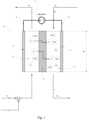
- the electrochemical cell 0 required for carrying out the process is in Figure 1 It comprises a first compartment 1 and a second compartment 2. Both compartments 1, 2 are separated from each other by a membrane 3. An anode 4 is arranged in the first compartment 1. A cathode 5 is arranged in the second compartment 2.
- the first compartment 1 can therefore also be referred to as an anodic compartment, while the second compartment 2 is referred to as cathodic.
- a first electrical line 6 connects the anode 4 to a voltage source 7.
- a second electrical line 8 connects the cathode 5 to the voltage source 7.
- the polarity of the voltage source 7 is selected such that the positive pole of the voltage source 7 is connected to the anode 4, while the negative pole of the voltage source 7 is connected to the cathode 5. This polarity is always maintained, even if the amount of the electrical voltage U drawn from the voltage source 7 changes over time. In the simplest case, however, U is constant over time.
- the membrane 3 is a flat membrane made entirely of LiSICon material.
- the anode 4 is a metallic, flat sheet containing titanium, niobium or tantalum.
- the cathode 5 is also a flat metal sheet containing titanium or nickel. In the simplest case, stainless steel sheet is used as the cathode.
- Anode 4, cathode 5 and membrane 3 have the same shape, they can be rectangular or circular. This is shown in the side view of the Figure 1 not recognizable. Instead of metal sheets, expanded metal, grids or nets made of the specified materials can also be used as electrodes.
- the electrochemical cell 0 has an active area A, which corresponds to the surface area of the membrane 3, the anode 4 and the cathode 5.
- the intermediate 9 is an aqueous solution containing Li+ cations. From an electrochemical point of view, the intermediate 9 can be regarded as an anolyte.
- the intermediate 9 is obtained by mixing a feed 10 with a basic compound 11.
- the feed 10 can be a Li lye from a natural deposit or a material stream that accrues during the processing of spent LIB.
- the concentration of the Li+ cations in the feed 10 should be at least 200 ppm by weight, based on the total mass of the feed. Seawater has a lower Li concentration and would therefore have to be concentrated before it is used in the process.
- the feed 10 also contains anions such as sulfate or chloride.
- the feed 10 also contains impurities. Anions and impurities are in Figure 1 not shown.
- Main component of feed 10 is water H 2 O.
- the pH value of the feed is between 2 and 9.
- the basic compound 11 is ideally calcium hydroxide Ca(OH) 2 (slaked lime).
- the purpose of adding the basic compound 11 to the feed 10 is to increase the pH value into the alkaline range, more precisely to a pH value between 9 and 13.
- the electrochemical processes in the cell are carried out in a basic environment.
- the dose of the basic compound 11 is therefore chosen so that the pH of the intermediate assumes a value between 9 and 13.
- the intermediate 9 is fed into the first compartment 1.
- the second compartment is charged with a poor working medium 12.
- the poor working medium 12 is water H 2 O with a low concentration C M0 Li + cations.
- the concentration c M0 is at least 50 ppm by weight based on the total mass of the poor working medium 12. From an electrochemical point of view, the poor working medium 12 is to be regarded as a catholyte.
- the electrochemical cell 0 is also subjected to an electrical voltage U obtained from the voltage source 7.
- LiOH in the cathodic compartment 2 is maintained by Li+ cations migrating from the intermediate 9 towards the cathode 5, driven by the voltage U. They overcome the membrane 3 due to its Li conductivity and accumulate in the working medium (membrane electrolysis). This creates a rich working medium 13, which is withdrawn from the second compartment 2.
- the concentration of Li+ ions in the rich working medium 13 is greater than in the poor working medium 12, c M1 > c M0 .
- Li+ membrane electrolysis and water electrolysis are operated simultaneously in the electrochemical cell, lithium hydroxide LiOH and molecular hydrogen H 2 are produced directly.
- the LiOH is dissolved in the water, the hydrogen is partially dissolved in the water and is also present in gaseous form.
- the water with the LiOH and the dissolved hydrogen is withdrawn from the cathodic compartment of the cell as a rich working medium 13. Gaseous hydrogen is also withdrawn from the second compartment 2.
- the intermediate 9 is depleted of Li + by the membrane electrolysis, so that a waste water 14 is created.
- c W ⁇ c F applies.
- the formula letter c W stands for the concentration of Li ions in the waste water 14, based on the total mass of the waste water 14.
- the formula letter c F stands for the concentration of Li ions in the feed 10, based on the total weight of the feed 10.
- a separation apparatus 16 is provided into which the rich working medium 13 is introduced.
- the separation apparatus 16 separates the target product 15, which has a particularly high concentration of LiOH, from the rich working medium 13.
- the target product also contains water and impurities, depending on the desired specification of the target product.
- the separation apparatus 16 may be a distillation column or a crystallizer.
- the LiOH-depleted output stream of the separation apparatus 16 is recycled as poor working medium 12 into the second compartment 2 of the electrochemical cell 0.
- the poor working medium 12 must contain a certain concentration C M0 of LiOH so that the process in the electrochemical cell 0 starts as desired thanks to a low starting resistance.
- the C M0 should be at least 50 ppm by weight based on the total mass of the poor working medium 12.
- the separation apparatus 16 is operated in such a way that it does not completely separate the LiOH from the rich working medium 13.
- the process In addition to lithium hydroxide LiOH, the process also produces hydrogen H 2 .
- the hydrogen H 2 is at least partially dissolved in the rich working medium 13 and is withdrawn from the second compartment 2 together with the LiOH. Part of the hydrogen exits the second compartment 2 in the gaseous state.
- the water H 2 O contained in the rich working medium 13 is almost completely recycled as a poor working medium 12. Only the water contained in the target product 15 is lost from the process. It must be added accordingly to the poor working medium 12 (not shown).
- the water contained in the intermediate 9 from the feed The water from the second compartment 2 does not enter the circuit between the second compartment 2 and the separation apparatus 16 because the membrane 3 is impermeable to water.
- the electrolysis cell is first assembled and connected to the anolyte and catholyte containers. Care is taken to ensure that the inlet and return lines are connected to the same side.
- a round disk with a diameter of 19.5 mm and a thickness of 1 mm was used as the anode and cathode.
- the material in each case was a titanium expanded metal sheet, coated on both sides with IrTi mixed oxide, 12 g Ir/m2, 1 AF D1.5 mm from Metakem GmbH, 61250 Usingen, Germany.
- the sampled membranes were also circular disks with a diameter of about 25 mm.
- the thickness of the membranes was about 1 mm.
- the material of the sampled membranes is indicated in the individual examples.
- the electrolysis and the corresponding storage containers are blanketed with nitrogen throughout the entire process to prevent the formation of lithium carbonate.
- Each cell has a separate anolyte and catholyte container.
- Each container is filled with about 1 kg of liquid, the exact mass is determined by back weighing.
- the catholyte was always a 5 mmol/L LiOH solution (corresponds to 120 ppm by weight LiOH).
- the anolyte is always a lithium salt solution in various concentrations and various lithium salts.
- the test is started by switching on the pumps and the desired voltage.
- the maximum flow rate is 900 mL/minute. Sampling takes place every half hour or at longer intervals as agreed. 3 mL of preliminary flow is taken and discarded. The current is noted for each sample and the pH value and conductivity of the sample are determined. The samples are then returned to the appropriate containers in order to keep the volume almost constant.
- the containers are emptied and all pipes and the membrane are rinsed with deionized water.
- the cell is disassembled, the membrane is photographed and SEM images are taken from the catholyte and anolyte sides to document any damage or changes to the membranes.
- the voltage supply is interrupted at a defined time interval so that no voltage is applied to the electrochemical cell during this time. Over time, the voltage runs in a rectangular shape without changing polarity. This is intended to flush the membrane free of any potentially disruptive ions (H') during the time without voltage, which reduces membrane damage and increases membrane performance.
- H' potentially disruptive ions
- the membrane performance is measured using the parameters of permeability (g Li*mm/m 2 *h) and permeance (g Li/m 2 *h). Permeance indicates how much mass of lithium is transported through the membrane per membrane area and time.
- the permeability also takes the membrane thickness into account and thus makes it possible to compare different membrane types with different thicknesses. Both pieces of information are needed to comprehensively describe the performance, as extremely thin membranes would enable an extremely high permeance, but if concentration polarization effects occur in the membrane cell, the permeabilities would be incorrectly represented. Taking the membrane thickness into account is then no longer useful, as the transport is not limited by the membrane.
- Lithium hydroxide was used by Aldrich in p.a. quality. All other materials were used in technical qualities.
- membranes made of LATSP (LICGC ® , Ohara) were used.
- the membrane discs were manufactured using an SPS sintering process at a pressure of 100*10 5 Pa to 200*10 5 Pa and a temperature of 950°C, or alternatively purchased directly from various manufacturers (Ohara, Ampcera, Toshima) in the size suitable for the measuring cells.
- the LATSP powder used is sintered using FAST/SPS (field assisted sintering technology / spark plasma sintering). Sintering is carried out with a simultaneous increase in pressure and temperature in order to achieve high compaction and effective sintering in a very short sintering time.
- the structure of the sintering mold consists of a graphite matrix with an outer diameter of 80 mm, an inner diameter of 36 mm and a height of 55 mm, two graphite half-shells with a wall thickness of 10 mm and the same height and two graphite stamps with a diameter of 25 mm and a height of 30 mm. The half-shells are positioned in the matrix and a stamp is inserted into the half-shells from the bottom.
- graphite foil is positioned on the stamp to improve contact.
- a second graphite foil is positioned on the powder and the upper punch is inserted into the half shells.
- the matrix structure is positioned in the furnace chamber of the FAST/SPS furnace between two plates made of carbon fiber reinforced graphite. The structure is contacted via the travel path of the electrodes and the desired pressure is built up.
- the matrix is heated using an alternating current, which means that high temperatures are reached in a short time. After a slow temperature increase to 250 °C over five minutes, the maximum temperature of 900 °C is reached at a heating rate of 130 °C/min, which is maintained for a further five minutes.
- the pressure is also increased to 43 MPa within five minutes, which is also maintained for five minutes.
- the contact of the upper electrode is released from the matrix and the matrix cools down.
- the sintered membrane can then be removed from the mold.
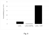
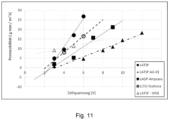
- the electrolysis was carried out with 0.1 mol/L lithium of the corresponding lithium salt in the anolyte circuit at 3 V, 4 V and 6 V.
- the permeabilities are of a comparable magnitude at the beginning of an experiment after a short running time (given in brackets).
- the permeability can be increased by a higher voltage, as expected, but for lithium chloride and lithium sulfate, the permeability decreases with longer running time and at higher voltages.
- a low pH value and an increased voltage (3 to 8 V) do not lead to stable, constant permeabilities.
- the pH value varies depending on the running time until it settles at around pH 4 during the test and thus the permeability does not assume a constant value over the test period.
- the pH of the anolyte circuit was adjusted with calcium hydroxide (Ca(OH) 2 ) in this experiment. Since calcium hydroxide is poorly soluble, it is difficult to add more if the pH drops: the intermediate contained solids and was slightly cloudy. The experiment was carried out with a 0.1 mol/L lithium chloride solution, the pH of which was adjusted to 12 with Ca(OH) 2 .
- Lithium carbonate as a salt in the anolyte behaves differently than lithium chloride and sulfate.
- the performance of the membrane is slightly lower than at 6 V.
- the permeability settles at a stable level, so that an increase in voltage does not lead to an increase in permeability.
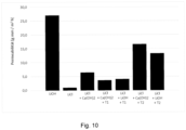
- the voltage is switched on for 50 seconds and off for 10 seconds and a permeability improvement of 61% is achieved.
- the properties of the materials can be derived very well; however, it should also be noted that a material with lower permeability can be used well in the described process if the materials are processed into thin membranes.
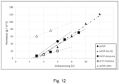
- LATSP stands for LICGC ® PW01
- LATSP-AG-01 for LiCGC ® AG01
- LATSP-SP01 for LiCGC ® SP-01 from Ohara
- LAGP stands for the Ampcera material and LLTO for that from Toshima.
- the behavior of the different ceramics can also be described by the respective permeance ( Fig. 12 ).
- This representation is more suitable when the mass transport in the electrolysis cell is limited.
- the reason why the LATSP SP01 differs from the other LiSICons examined in this representation may be that this material is very thin at 0.15 mm and is therefore not as stable as the other materials examined.
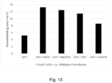
- a basic anolyte solution was contaminated with approximately 1000 ppm (g/g) of each of the following cations: sodium; potassium; magnesium; calcium.
- the lithium can be separated from the solution with the Figure 13 compiled permeabilities into the catholyte.
- all catholytes contained less than 10 ppm of the corresponding impurities.
- a voltage pulse of 5 V was used as in Example 9, Pulse 2.
- the lithium can be separated from the solution with the Figure 14 shown permeability in the catholyte.
- the cell voltage was 5V, clocked with the clock T2, as described in Example 9.
- the purified LiOH contained less than 10 ppm sodium ions according to ion chromatographic analysis.
- Example 11 and 12 the contents of Li and Na ions in anolyte and catholyte were determined by ion-exchange chromatography (IEC) as follows: The samples were filtered before measurement using a syringe filter (type Chromafil ® Xtra MV-20/25, pore size 0.20 ⁇ m, for aqueous and polar media).
- IEC ion-exchange chromatography
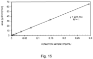
- the IEC device (Metrohm IC 930 Compact, C Supp C6 250/4.0, standard (1.7 mM HNOs, 1.7 mM dipicolinic acid), conductivity sensor) was referenced and externally calibrated for Li and Na.
- the calibration lines used are shown in the Figures 15 (for Na) and 16 (for Li).
Landscapes
- Chemical & Material Sciences (AREA)
- Engineering & Computer Science (AREA)
- Organic Chemistry (AREA)
- Materials Engineering (AREA)
- Chemical Kinetics & Catalysis (AREA)
- Electrochemistry (AREA)
- Metallurgy (AREA)
- Inorganic Chemistry (AREA)
- Life Sciences & Earth Sciences (AREA)
- Environmental & Geological Engineering (AREA)
- Water Supply & Treatment (AREA)
- Hydrology & Water Resources (AREA)
- General Chemical & Material Sciences (AREA)
- Manufacturing & Machinery (AREA)
- Mechanical Engineering (AREA)
- Geology (AREA)
- General Life Sciences & Earth Sciences (AREA)
- Analytical Chemistry (AREA)
- Health & Medical Sciences (AREA)
- Geochemistry & Mineralogy (AREA)
- Molecular Biology (AREA)
- Automation & Control Theory (AREA)
- Urology & Nephrology (AREA)
- Electrolytic Production Of Non-Metals, Compounds, Apparatuses Therefor (AREA)
- Manufacture And Refinement Of Metals (AREA)
- Water Treatment By Electricity Or Magnetism (AREA)
- Hydrogen, Water And Hydrids (AREA)
Description
- Für die Herstellung von Lithiumionenbatterien (LIB) wird denknotwendig Lithium (Li) benötigt. Aufgrund seiner hohen Reaktivität kommt Lithium in der Natur nicht als Reinstoff, sondern stets gebunden vor. Als Ausgangstoff für die Herstellung von LIB wird das Lithium in der Regel in Form von Lithiumhydroxid (LiOH) oder von Lithiumcarbonat (Li2CO3) verwendet.
- In den meisten natürlichen Lagerstätten ist Li in Form von Lithiumoxid (LizO) oder von Salzen wie Lithiumsulfat (Li2SO4) oder Lithiumchlorid (LiCl) vorhanden. Das Lithiumoxid ist Bestandteil von Erzen wie Pegmatit, wahrendessen Lithiumsulfat und Lithiumchlorid in den Laugen der Li-Salzseen gelöst sind. Im Zuge des bergmännischen Abbaus wird die jeweils gewonnene Lithiumverbindung in Lithiumcarbonat (Li2CO3) überführt. In einem weiteren Prozessschritt kann das Lithiumcarbonat mit Branntkalk oder Calciumhydroxid in Lithiumhydroxid umgesetzt werden. Die Gewinnung von Li und dessen Umwandung in LiOH ist beschrieben in:
Wietelmann, U. and Steinbild, M. (2014). Lithium and Lithium Compounds. In Ullmann's Encyclopedia of Industrial Chemistry, (Ed.). DOI: 10.1002/14356007.a15_393.pub2 - Reiche Li-Lagerstätten sind bekannt, aber die Herstellung von LiOH aus den dort vorhandenen Li-Verbindungen ist sehr energieintensiv- und abwasserintensiv. Darüber hinaus besteht das strategisch begründete Bedürfnis, von den Eigentümern der Lagerstätte unabhängig zu sein.
- Eine Lösung dieses Problems könnte darin bestehen, abgenutzte LIB stofflich aufzuarbeiten, sodass das darin enthaltene Lithium wieder als Rohstoff für Neubatterien verwendet werden kann.
- Recyclingverfahren für LIB wurden in der Vergangenheit bereits zur technischen Reife entwickelt, jedoch meist mit dem Ziel auf die darin enthaltenen Metalle Fe, Ni, Mn, Co, Mg, Al. Das Alkalimetall Li wurde in der Regel nicht zurückgewonnen, weil es auf Grund seiner hohen Reaktivität nicht einfach aus dem Batterieschrott abzutrennen ist und es in ausreichender Menge kostengünstig aus natürlichen Lagerstätten verfügbar war. Die Gewinnung vom Li aus gebrauchten LIB erschien lange Zeit schlicht unwirtschaftlich.
- Inzwischen ist der gesellschaftliche und wirtschaftliche Druck gestiegen, Lithium aus gebrauchten LIB zurückzugewinnen. Der Erfolg dieses Vorhabens setzt voraus, dass rezykliertes Li in einer für die Produzenten von LIB akzeptablen Qualität angeboten werden kann, sodass sich die Herstellungsprozesse für LIB aus Recycling-Li nicht von denen aus bergmännisch gewonnenen Frisch-Li unterscheiden. Die Batteriequalität darf selbstredend nicht leiden. Folglich muss rezykliertes Li, insbesondere in Form von LiOH, sehr anspruchsvolle Spezifikationen hinsichtlich Reinheit erfüllen. Darüber hinaus muss das Verfahren zur Rückgewinnung von Li aus Altbatterien möglichst energieeffizient sein. Ebenso sollte das Verfahren wenig Wasser verbrauchen.
- Bekannte Verfahren zur Rückgewinnung von Lithium aus Altbatterien haben zusammengestellt:
- Pankaj K. Choubey et al.: Advance review on the exploitation of the prominent energystorage element Lithium. Part II: From sea water and spent lithium ion batteries (LIBs), Minerals Engineering, Volume 110, 2017, Pages 104121
- DOI: 10.1016/j.mineng. 2017.04.008.
- Eine Technologie, die im vorstehenden Übersichtsartikel lediglich beiläufig als "LISM" erwähnt wird, ist die Elektrolyse von Li-haltigen Wässern in Gegenwart von so genannten LiSICon-Membranen.
- LiSICon steht für Lithium Super lonic Conductor. Es handelt sich dabei um eine Klasse aus anorganischem, (glas)keramischen Material, welches elektrisch isoliert, aber zugleich eine intrinsische Leitfähigkeit für Li-Ionen aufweist. Der Transportmechanismus für Li ist in der Kristallstruktur des Materials begründet. Die Li-Ionen werden - vereinfacht gesprochen - durch die Kristalle "durchgereicht". Kommerziell verfügbare LiSICon-Materialien sind unter anderem Lithium-Aluminium-Titanphosphat (LATP), Lithium-Aluminium-Titan-Siliciumphosphat (LATSP), Lithium-Aluminium-Germaniumphosphat (LAGP) und Lithium-Lanthan-Titanoxid (LLTO). Diese Materialien wurden ursprünglich als Festkörper-Elektrolyt für LIB entwickelt. Eine Übersicht zu den Transportmechanismen von LiSICons, deren Kristallstruktur und Herstellung bieten:
- Palakkathodi Kammampata et al.: Cruising in ceramics-discovering new structures for all-solid-state batteries-fundamentals, materials, and performances. Ionics 24, 639-660 (2018) DOI: 10.1007/s11581-017-2372-7
- Yedukondalu Meesala et al.: Recent Advancements in Li-lon Conductors for All-Solid-State Li-Ion Batteries. ACS Energy Lett. 2017, 2, 12, 2734-2751
- DOI: 10.1021/acsenergylett.7b00849
- Spezielle LiSICon Stöchiometrien werden beschrieben von:
- Sofia Saffirio et al.Li1.4Al0.4Ge0.4Ti1.4(PO4)3 promising NASICON-structured glass-ceramic electrolyte for all-solid-state Li-based batteries: Unravelling the effect of diboron trioxide, Journal of the European Ceramic Society, Volume 42, Issue 3, 2022, Pages 1023-1032 DOI 10.1016/j.jeurceramsoc.2021.11.014.
- Eongyu Yi et al. Materials that can replace liquid electrolytes in Li batteries: Superionic conductivities in Li1.7Al0.3Ti1.7Si0.4P2.6O12. Processing combustion synthesized nanopowders to free standing thin films. Journal of Power Sources, Volume 269,
- 2014, Pages 577-588, DOI 10.1016/j.jpowsour.2014.07.029.
- Aufgrund ihrer selektiven Leitfähigkeit für Li-Ionen können LiSICon-Materialien als Membran zur Abtrennung von Li aus Li-haltigen Gemischen verwendet werden. Das Li muss in dem Gemisch in ionischer Form vorliegen, etwa als in Wasser gelöstes Li-Salz. Als treibende Kraft, um die Li-Ionen durch die LiSICon -Membran zu fördern, wird eine elektrische Spannung benötigt. Hierfür wird eine elektrochemische Zelle aufgebaut, die zwei Elektroden und eine LiSICon-Membran umfasst, welche die Zelle in zwei Kompartimente aufteilt. In jedem Kompartiment befindet sich eine Elektrode. Abhängig von der Polarität der im Kompartiment enthaltenen Elektrode werden die Kompartimente als anodisch oder kathodisch bezeichnet. An den Elektroden wird eine elektrische Spannung angelegt und das Li-haltige Wasser in das anionische Kompartiment eingefüllt. Das kathodische Kompartiment wird mit Wasser gefüllt. Die Membran reicht die Li-Kationen zu der Kathode durch. Das Wasser in dem kathodischen Kompartiment wird daher mit Li angereichert, während das Wasser auf der anodischen Seite um Li abgereichert wird. Ein solcher Vorgang wird Membranelektrolyse genannt.
- Membranelektrolytische Verfahren zur Gewinnung von Lithium mit Hilfe von LiSICon Membranen sind bereits im Stand der Technik beschrieben.
- So beschreiben Zhen Li et al. ein Verfahren, bei dem als Rohstoff das schwach Lithium-haltige Wasser des Roten Meeres verwendet wird:
Zhen Li et al.: Continuous electrical pumping membrane process for seawater lithium mining. Energy Environ. Sci., 2021, 14, 3152 DOI: 10.1039/d1ee00354b - Die Arbeitsgruppe um Zhen Li verwenden LLTO als Membran. Das abgetrennte Zielprodukt ist Lithiumphosphat (Li3PO4), was für die Produktion von Lithium-Eisen-Phosphat (LFP) Batterien in Betracht kommt. LlB mit einem anderen Kathodenmaterial wie beispielsweise Nickel-Mangan-Cobalt (NMC) oder Lithium-Mangan-Oxid (NMO) können damit nicht direkt hergestellt werden.
- Mithilfe von Solarstrom, einer LAGP Membran und einer Kupferfolie wollen Yang et al. metallisches Lithium direkt aus Meerwasser gewinnen:
Sixie Yang et al.: Lithium Metal Extraction from Seawater. Joule, Volume 2, Issue 9, 2018, Pages 1648-1651, DOI 10.1016/j.joule.2018.07.006. -
US 2016/0201163 A1 beschreibt die Abtrennung von Li Ionen aus einer Sole wie Meerwasser mit Hilfe von LiSICon Membranen. Als Membranmaterialien werden konkret Li3N, Li10GeP2S12 und LaxLiyTiO2, Li1+x+yAlx(Ti, Ge)2-xSiyP3-yO12 vorgeschlagen. Zielprodukt ist Lithiumcarbonat (Li2CO3). - Auch die
WO 2019055730 A1 beschäftigt sich mit der Abtrennung von Lithium mit Hilfe von LiSICon-Membranen. Konkret werden LLTO oder LAGP oder LATP genannt. Das LiSICon-Material kann auf eine Stützstruktur aufgetragen sein. Die chemische Natur der Stützstruktur wird nicht näher beschrieben. Ebenso wenig wird beschrieben, wie das Auftragen von LiSICon auf die Stützstruktur geschehen soll. Das abgetrennte Zielprodukt sind Li-Ionen. - Aus der
US9222148B2 - Neben der Verwendung von keramischen LiSICon Membranen sind auch elektrolytische Verfahren zur Abtrennung von Lithium bekannt, die mit organischen lonenaustauschmembranen arbeiten.
- So beschreibt die
EP 3805428 A1 die elektrolytische Herstellung von Lithiumhydroxid. Neben der Elektrolyse wird eine elektrochemische Umsetzung des Lithiums zu Lithiumhydroxid betrieben. Zur Gewinnung der notwendigen Edukte wird gleichzeitig Wasser elektrochemisch gespalten. Hierzu wird eine bipolare Dreikammerzelle mit einer lonenaustauschmembran verwendet. Es werden die kommerziellen lonenaustauschmebranen Asahi® AVV, Nation® 902, Fumatech® FAB, Fumatech® FKB und Neosepta® CMB verwendet. Die chemische Natur dieser lonenaustauschmembranen ist inEP 3805428 A1 nicht offengelegt, aber es ist überwiegend wahrscheinlich, dass es sich dabei um organische Membranmaterialien handelt. Die Dreikammerzelle arbeitet im sauren Milieu. Als Feed wird Wasser enthaltend Li-Salze wie insbesondere Lithiumsulfat (Li2SO4) oder Lithiumchlorid (LiCl) eingesetzt. - Aus die
US2012/103826 ist ein alternatives Verfahren zur Herstellung von Lithium-Hydroxid bekannt, - Eine zweitstufige elektrodialytische/elektrolytische Herstellung von Lithiumhydroxid aus wässrigem Lithiumsufat und/oder Lithiumbisulfat bei gleichzeitiger Wasserspaltung offenbart
US 10036094 B2 - Ein prinzipieller Nachteil von Polymermembranen ist ihre Wasserdurchlässigkeit. Dadurch wird der Anolyt mit Wasser aus dem Katholyt verdünnt. Außerdem sind organische lonenaustauschmembranen weniger ionenselektiv als anorganische LiSICon-Materialien: Sie lassen nicht nur Li+, sondern auch Na+ passieren, sodass die Stoffreinheit des Zielproduktes beeinträchtigt wird, sobald sich im Feed auch Na befindet. Neben der Reinheit des Zielprodukts leidet auch die Stromeffizienz des Prozesses: Die wertvolle elektrische Energie wird bei der Elektrolyse mit nicht-ionenselektiven Membranen auch dafür verbraucht, unerwünschtes Na+ in das zweite Kompartiment zu transportieren. Im zweiten Kompartiment angekommen wird das Na+ zudem über unbeabsichtigte elektrochemische Prozesse in unerwünschte Nebenprodukte umgesetzt. Bezogen auf die Ausbeute an dem Zielprodukt Li ist die Energieeffizienz des Prozesses eingeschränkt. Schließlich sind diese Membranen empfindlich gegen die Anwesenheit von zweiwertigen Kationen wie bspw. Mg2+ und Ca2+ Diese Kationen vergiften die Membran mit der Zeit, sodass die Betriebsdauer organischer lonenaustauschmembranen eingeschränkt ist.
- Eine bessere lonenselektivität versprechen die (glas)keramischen LiSICon Materialien. Ein für die industrielle Praxis hochrelevantes Problem ist hier jedoch weiterhin die Stabilität der LiSICon Membran gegenüber Verunreinigungen. So enthalten die Li+ -haltigen Wässer, die bei der Aufarbeitung von gebrauchten LIB entstehen, weitere Kationen wie insbesondere Na+ und K+, welche das LiSICon-Material nachhaltig schädigen: Diese Kationen besetzen offenbar dauerhaft die Fehlstellen in der Kristallstruktur, sodass ein Transport der Li+-Kationen durch die Membran kaum mehr möglich ist. Die Betriebsdauer der elektrochemischen Zelle ist dann abgelaufen. Weil LiSICon-Material sehr teuer ist, ist das Recycling von Li aus LlB bei kurzer Lebensdauer der Membran unwirtschaftlich. Auch die Sole der Li-Salzseen enthält von Natur aus viel Natrium und kann daher nicht auf bekannte LiSICon-Membranen losgelassen werden. Daher wird Lithium aus Salzseen weiterhin energieintensiv thermisch abgetrennt und/oder unter großem Wassereinsatz schrittweise gelöst und wieder auskristallisiert. Zwar wird dabei das Wasser mit Sonnenstrahlung verdunstet; jedoch ist das Wasser zum Lösen von LiCl in den Wüsten Südamerikas rar. So führt dieser Weg dort zu großen Problemen.
- Ein weiteres praktisches Problem ist der hohe spezifische elektrische Widerstand des LiSICon-Materials. Dadurch erhält die elektrochemische Zelle einen hohen OHM'schen Innenwiderstand, sodass das Verfahren einen entsprechend großen elektrischen Energiebedarf hat. Um den zu senken, kann die Membran theoretisch verdünnt werden. Jedoch erreicht sie dann aufgrund ihrer geringen Materialstärke in aggressiven Umgebungen wiederum nur eine geringe Standzeit.
- Nach alledem liegt der vorliegenden Erfindung die Aufgabe zu Grunde, ein Verfahren zur elektrochemischen Herstellung von LiOH aus Li+-haltigem Wasser mit Hilfe einer LiSICon Membran anzugeben, welches sich auch im großtechnischen Maßstab wirtschaftlich betreiben lässt. Insbesondere soll das Verfahren eine hohe Energieeffizienz aufweisen und selbst dann eine lange Standzeit der Membran erreichen, wenn der verwendete Feed Verunreinigungen enthält, welche für LiSICon Materialien schädlich sind.
- Gelöst wird diese Aufgabe durch ein Verfahren nach Anspruch 1.
- Ein erster Gegenstand der Erfindung ist mithin ein Verfahren zur Herstellung von Wasserstoff und Lithiumhydroxid mit den folgenden Schritten:
- a) Bereitstellen eines Feed enthaltend zumindest Wasser, Li-Kationen, Anionen, sowie Verunreinigungen, wobei die Konzentration von Li-Kationen in dem Feed CF mindestens 200 Gew.-ppm oder zwischen 500 Gew.-ppm und 140000 Gew.-ppm beträgt, jeweils bezogen auf das Gesamtgewicht des Feeds, wobei der bei 25°C mittels Glaselektrode gemessene pH-Wert des Feeds zwischen 2 und 9 beträgt;
- b) Bereitstellen eines armen Arbeitsmediums enthaltend Wasser und darin gelöst Lithiumhydroxid, wobei die Konzentration von Lithiumhydroxid in dem armen Arbeitsmedium C M0 bezogen auf das Gesamtgewicht des armen Arbeitsmediums mindestens 50 Gew.-ppm beträgt;
- c) Bereitstellen einer basischen Verbindung;
- d) Bereitstellen von mindestens einer elektrochemischen Zelle, wobei die elektrochemische Zelle die folgenden Merkmale aufweist:
- i. die elektrochemische Zelle umfasst ein erstes Kompartiment, in dem eine Anode angeordnet ist;
- ii. die elektrochemische Zelle umfasst ein zweites Kompartiment, in dem eine Kathode angeordnet ist;
- iii. die elektrochemische Zelle umfasst eine Membran, welche das erste Kompartiment von dem zweiten Kompartiment trennt, wobei die Membran die Fläche A aufweist;
- iv. die Membran enthält ein anorganisches Material, welches eine Leitfähigkeit für Li-Ionen besitzt und welches elektrisch isolierend ist;
- e) Bereitstellen von mindestens einer elektrischen Spannungsquelle, welche über eine erste elektrische Leitung mit der Anode und über eine zweite elektrische Leitung mit der Kathode verbunden ist;
- f) Dosierung der basischen Verbindung zu dem Feed, sodass ein Intermediat erhalten wird, wobei der mittels Glaselektrode bei 25°C gemessene pH-Wert des Intermediats zwischen 9 und 13 beträgt,
- g) Beaufschlagen des ersten Kompartiments mit dem Intermediat;
- h) Beaufschlagen des zweiten Kompartiments mit dem armen Arbeitsmedium;
- i) Beaufschlagen der elektrochemischen Zelle mit einer von der elektrischen Spannungsquelle bezogenen elektrischen Spannung U, dergestalt, dass ein elektrischer Strom I zwischen Anode und Kathode fließt, wobei der Quotient Q aus der Stromstärke des elektrischen Stroms I und der Fläche A der Membran zwischen 100 A/m2 und 500 A/m2 oder zwischen 150 A/m2 und 350 A/m2 beträgt;
- j) Abziehen von Abwasser enthaltend zumindest Wasser, darin gelöste Li-Salze, Sauerstoff, sowie Verunreinigungen aus dem ersten Kompartiment, wobei die Konzentration von Li-Ionen in dem Abwasser Cw bezogen auf das Gesamtgewicht des Abwassers geringer ist als die Konzentration von Li-Ionen im Feed CF;
- k) Abziehen eines reichen Arbeitsmediums enthaltend Wasser und Lithiumhydroxid sowie Wasserstoff aus dem zweiten Kompartiment, wobei die Konzentration von Lithiumhydroxid in dem reichen Arbeitsmedium C M1 bezogen auf das Gesamtgewicht des reichen Arbeitsmediums größer ist als die Konzentration im von Lithiumhydroxid in dem armen Arbeitsmedium C M0.
- Ein besonderer Aspekt des erfindungsgemäßen Verfahrens ist, dass in der Zelle gleichzeitig das Lithium durch die Membrane selektiv abgetrennt wird und eine Elektrolyse von Wasser erfolgt. Bei der Wasserelektrolyse wird Wasser (H2O) elektrochemisch in H2 und O2 getrennt. An der Kathode wird OH- und Wasserstoff gebildet. Die OH- - Anionen können die LiSICon-Membran jedoch nicht überwinden und verbinden sich mit den im kathodischen Kompartiment ankommenden Li+ - Kationen zu Lithiumhydroxid LiOH. An der Anode wird Sauerstoff und H+ gebildet.
- Bei dem gleichzeitigen Betrieb der Li+ Membranabtrennung und der Wasserelektrolyse in der elektrochemischen Zelle mit LiSICon Membran entstehen somit direkt Lithiumhydroxid LiOH und molekularer Wasserstoff H2. LiOH ist in Wasser gelöst, H2 zu einem kleinen Teil auch, zum größten Teil aber als Gas ausgetrieben. Das Wasser mit dem LiOH sowie das gelöste und gasförmige H2 werden aus dem kathodischen Kompartiment der Zelle abgezogen. Das LiOH wird von dem Wasser abgetrennt. Auf diese Weise kann ein LiOH gewonnen werden, welches - aufgrund der selektiven Lithium-Ionen-Wanderung durch die Membran- eine entsprechende Reinheit besitzt - in der Batterieproduktion verwendet werden kann.
- Der zugleich entstandene Wasserstoff kann aufgefangen und in der Wasserstoffwirtschaft eingesetzt werden. Sofern die elektrochemische Zelle mit grünem Strom betrieben wird, hinterlässt das Verfahren auch einen geringen CO2-Fußabdruck.
- Als Feed für die kombinierte Li Abtrennung und Wasserelektrolyse wird ein Wasser mit enthaltenden Li+ Kationen benötigt. Ein solches Wasser wird entweder im Zuge der Aufarbeitung verbrauchter LIB erzeugt oder es wird eine Li-Sole aus einer natürlichen Lagerstätte verwendet.
- Ein wesentlicher Aspekt des erfindungsgemäßen Verfahrens besteht darin, dass der elektrochemische Prozess im basischen Milieu, genauer gesagt bei pH 9 bis 13 durchgeführt wird. Dies ermöglicht die effiziente Wasserelektrolyse, welche wiederum die Vorrausetzung für die direkte Herstellung von LiOH ist. Außerdem deuten erste Langzeitversuche darauf hin, dass LiSICon Materialen in diesem pH-Bereich eine besonders lange Standzeit aufweisen - selbst bei hohen Stromdichten.
- Ein pH-Wert zwischen 9 und 13 herrscht vorzugsweise sowohl im ersten Kompartiment als auch im zweiten Kompartiment. Der pH-Wert kann in beiden Zellen gleich sein oder unterschiedlich, solange der jeweilige Wert zwischen 9 und 13 liegt. Bei Betrachtung der Halbzellreaktionen der Wasserzersetzung stellt sich nämlich heraus, dass die Kombination einer mit einem sauren Feed betriebenen Anolytzelle mit einer mit einem basischen Arbeitsmedium betriebenen Katholyt-Zelle eine höhere Spannung für die Wasserzersetzung benötigt als die Kombination von zwei Halbzellen mit jeweils basischem Feed. Somit ist ein basischer pH-Wert in beiden Halbzellen (Kompartimente) besonders vorteilhaft, da so eine geringere Spannung für die gleichen Prozesse benötigt wird. Verglichen mit einem Prozess, bei dem im anolytischen Kompartiment ein saurer pH vorliegt, währenddessen im kathodischen Kompartiment ein basischer pH herrscht, liegt die Energieeinsparung aufgrund der reduzierten Spannung bei einem in beiden Kompartimenten basischen Prozess im Bereich von ca. 5 bis 15%, je nachdem, welche Spannungslage für den Membranprozess gewählt ist.
- Da die lithiumhaltigen Wertstoffströme aus dem Batterierecycling oder das Meerwasser in der Regel meist nicht basisch, sondern tendenziell eher sauer sind (pH 4 bis 9), wird erfindungsgemäß der pH-Wert durch Zugabe einer basischen Verbindung zum Feed eingestellt. Erst das so erhaltene Intermediat mit dem gewünschten pH-Wert von 9 bis 13 wird in die Zelle gefahren. Die pH-Werte sind für Temperaturen von 25°C angeben. Die pH Messung erfolgt per Glaselektrode, die mit einer kommerziell verfügbaren Prüfflüssigkeit kalibriert wird.
- Das kathodische Kompartiment wird erfindungsgemäß mit einem Arbeitsmedium beaufschlagt. Dabei handelt es sich um Wasser mit unterschiedlicher Konzentration an LiOH. Im Zulauf zum zweiten Kompartiment beträgt die Konzentration cM0 an LiOH mindestens 50 Gew.-ppm. Im Ablauf ist die Konzentration cM1 an LiOH viel größer. Deswegen wird der Zulauf als "armes Arbeitsmedium" bezeichnet, währenddessen der Ablauf "reiches Arbeitsmedium" genannt wird. Die Attribute arm und reich betreffen den Gehalt an LiOH. Die Untergrenze von LiOH im armen Arbeitsmedium cM0 > 50 Gew.-ppm ist einzuhalten, damit der Prozess mit einem geringen elektrischen Widerstand im Arbeitsmedium starten kann: Es hat sich gezeigt, dass die gewünschte Herstellung von LiOH und H2 sehr viel schlechter gelingt, wenn das zweite Kompartiment mit Wasser beaufschlagt wird, das frei von LiOH ist. Eine konkrete Obergrenze der LiOH Konzentration im armen Arbeitsmedium gibt es nicht. Allerdings muss cM0 < cM1 gelten, da der Prozess andernfalls kein LiOH produziert. Die 50 Gew.-ppm LiOH entsprechen 15 Gew.-ppm Lithium.
- Ein weiterer wesentlicher Aspekt des erfindungsgemäßen Verfahrens ist die hohe Stromdichte, bei dem es betrieben wird. Konkret beträgt die Stromdichte, also der Quotient Q aus der Stromstärke des elektrischen Stroms I und der Fläche A der Membran zwischen 100 A/m2 und 500 A/m2, oder vorzugsweise zwischen 150 A/m2 und 350 A/m2. Diese hohen Stromdichten erlauben einerseits eine hohe Stromeffizienz, erfordern aber anderseits eine gute Stabilität des Membranmaterials unter harschen Bedingungen. Als Membranmaterial wird daher ein anorganisches Material gewählt, welches einerseits elektrisch isolierend ist und anderseits Li-Ionen leiten kann. Beispiele für ein geeignetes Membranmaterial sind (glas)keramische LiSICons.
- Als basische Verbindung, die zur Einstellung des pH-Wertes des Intermediat verwendet wird, wird vorzugsweise einer der folgenden Stoffe oder Mischungen davon eingesetzt: Calciumhydroxid (Ca(OH)2), Kaliumhydroxid (KOH), Natriumhydroxid (NaOH), Lithiumhydroxid (LiOH), Ammoniumhydroxid (NH4OH). Vorzugsweise werden diese Stoffe als wässrige Lösungen eingesetzt, etwa Kalilauge, Natronlauge, Lithiumlauge oder Ammoniakwasser. Diese wässrigen Lösungen lassen sich gut dosieren. Kalilauge und Natronlauge sind vergleichsweise preiswert. Lithiumlauge wird vorzugsweise in dem Prozess selbst hergestellt.
- Ganz besonders bevorzugt wird als basische Verbindung Ca(OH)2 eingesetzt. Insbesondere wird Calciumhydroxid in seiner hydratisierten Form eingesetzt, nämlich als Löschkalk. Löschkalk ist leicht verfügbar. Gegenüber Kalilauge und Natronlauge hat Löschkalk den Vorteil, dass er kaum K und Na enthält. Folglich wird das Intermediat nicht mit den Membrangiften K+ und Na+ konterminiert.
- Optimalerweise wird die basische Verbindung zu dem Feed so dosiert, dass der bei 25°C mittels Glaselektrode gemessene pH-Wert des Intermediats zwischen 9 und 12 beträgt. In diesem pH-Fenster funktioniert die Wasserspaltung ganz gut und die Membran wird nicht angegriffen. Die Glaselektrode zur Bestimmung des pH-Wertes ist wie üblich mit einer definierten Prüfflüssigkeit zu kalibrieren.
- Die elektrochemische Zelle kann auch bei anderen Temperaturen als 25°C betrieben werden. Der pH-Wert ist nicht anzupassen: Das Intermediat sollte bei Zelltemperatur einen pH-Wert aufweisen, der einem pH von 9 bis 12 bei 25°C entspricht. Die Zelltemperatur kann 20°C bis 70°C betragen.
- Die Zugabe der basischen Verbindung hat auch den Vorteil, dass im Feed enthaltene, unerwünschte Ionen gebunden werden. Die Membran wird dadurch geschützt und die Reinheit des Produkts verbessert. Insbesondere ist es dank der Zugabe der basischen Verbindung möglich einen Feed zu verarbeiten, der eines oder mehrere der folgenden Anionen enthält: Sulfat, Carbonat, Hydroxid, Chlorid, Fluorid.
- Bei dieser Aufstellung ist eingeschlossen, dass sich in wässrigen Lösungen die Anionen mit den entsprechenden protonierten Ionen im Gleichgewicht befinden. Die genauen Konzentrationen sind dabei vom exakten pH-Wert der jeweiligen Lösung abhängig und lassen sich mit Hilfe der entsprechenden Säure- und Basenkonstanten berechnen. Die Berechnung ist dargestellt in:
Ruland (Hrsg.) et al: Analytik: Daten, Formeln, Übungsaufgaben. Auflage 109, 2019, Walter de Gruyter GmbH & Co. KG Seiten 257f. - Neben den genannten Anionen kann der Feed auch Verunreinigungen in Gestalt von Verbindungen von folgenden Elementen enthalten: B, Na, Mg, Al, Si, K, Ca, Mn, Fe, Co, Ni, Cu, C. Die gelisteten Alkali- und Erdalkalimetalle sind Begleitelemente des Lithiums aus natürlichen Lagerstätten, währenddessen die anderen genannten Metalle als Leiter- oder Kathodenmaterial in LIB verwendet werden und sich daher in Feeds finden, die bei der Aufarbeitung von verbrauchten LIB gewonnen werden. Der Kohlenstoff stammt aus organischen Verbindungen, die in LIB enthalten waren, etwa aus Folien, Separatoren, Dicht- oder Klebstoffen.
- Erfindungsgemäß wird eine Membran verwendet, welche ein anorganisches Material enthält. Anders als bei Polymermembranen ist damit die erforderliche lonenselektivität zu erreichen. Vorzugsweise besteht die Membran vollständig aus dem anorganischen Material. Verbundmembranen, die das anorganische Material lediglich als Beschichtung auf einem Trägermaterial enthalten oder bei denen das anorganische Material in einem andersartigen Matrixmaterial dispergiert ist, haben sich als Irrweg erwiesen.
- Damit der Prozess funktioniert, muss das anorganische Material Li-Ionen leiten und zugleich elektrisch isolieren.
- Die spezifische Leitfähigkeit σ für Li-Ionen sollte einer Temperatur von 23°C mindestens 1*10-5 S/m oder mindestens 5*10-5 S/m oder mindestens 10*10-5 S/m und maximal 100*10-5 S/m betragen. Die Li-Leitfähigkeit des Materials wird per Impedanz Spektroskopie gemessen. Diese Messung geschieht wie folgt:
Der Messaufbau umfasst zwei zylindrische Elektroden, zwischen denen die Probe angeordnet wird. Um einen optimalen Kontakt mit den Elektroden und reproduzierbaren Kontraktdruck sicher zu stellen, wird in Gewicht auf der Probe platziert. - Ein Potentiostat (ZAHNER-elektrik I. Zahner-Schiller GmbH & Co. KG, Kronach-Gundelsdorf, Germany) wird mit den Elektroden verbunden und über die Software Thales (ZAHNER) gesteuert. Die Messungen werden durchgeführt in einem Frequenzbereich von 1 Hz bis 4 MHz und einer Amplitude von 5mV mit Proben, die poliert wurden und auf die eine dünne, leitfähige Goldschicht aufgesputtert wurde.
- Die Messergebnisse werden in Nyquist-Diagrammen dargestellt und mit der Software Analysis (ZAHNER) ausgewertet. Der elektrische Widerstand wird an dem Maximum der Kurve des Nyquist-Diagramms abgelesen. Die spezifische lonen-Leitfähigkeit σ [mS/cm] wird dann berechnet mit der Formel σ=(h·104)/(R·π/4·d2), worin h für die Höhe der Probe in mm, R für den gemessenen elektrische Widerstand in Ω und d für den Durchmesser der Probe in mm stehen.
- Die spezifische Leitfähigkeit für Elektronen γ (elektrische Leitfähigkeit) sollte bei einer Temperatur von 23°C weniger als 10-7 S/cm (10-9 S/m) oder weniger als 10-12 S/m oder weniger als 10-16 S/m betragen. Das anorganische Material ist daher aus elektronenleitender Sicht als Nichtleiter zu qualifizieren.
- Vorzugsweise wird als anorganisches Material ein LiSICon verwendet. LiSICon-Materialien sind (glas)keramische Stoffe, die Lithium-Ionen leiten und zugleich elektrisch isolieren. Es können grundsätzlich alle bekannten LiSICon-Materialien als anorganisches Material im Sinne der Erfindung eingesetzt werden. Bekannte LiSICon-Materialien erfüllen die oben angegebenen Anforderungen sowohl an die elektrische Leitfähigkeit als auch an die lonenleitfähigkeit des anorganischen Materials.
- Beispielsweise kann das LiSICon-Material Lithium-Aluminium-Titanphosphat (LATP) verwendet werden. Dementsprechend sieht eine Variante der Erfindung es vor, dass es sich bei dem anorganischen Material um eine Verbindung der folgenden Stöchiometrie handelt:
Li1+xAlxTi2-x(PO4)3
worin gilt: 0.1≤x≤0.3, wobei bevorzugt gilt x=0.3. - Alternativ kann das LiSICon-Material Lithium-Aluminium-Germaniumphosphat (LAGP) verwendet werden. Dementsprechend sieht eine Variante der Erfindung es vor, dass es sich bei dem anorganischen Material um eine Verbindung der folgenden Stöchiometrie handelt:
Li1+xAlxGe2-x (PO4)3
worin gilt: x=0 oder x=0.2 oder x=0.4. - Alternativ kann das LiSICon-Material Lithium-Aluminium-Titan-Siliciumphosphat (LATSP) verwendet werden. Dementsprechend sieht eine Variante der Erfindung es vor, dass es sich bei dem anorganischen Material um eine Verbindung der folgenden Stöchiometrie handelt:
Li1+x+yAlxTi2-xSiyP3-yO12
worin gilt: 0.1≤x≤0.3 und 0.2≤y≤0.4. - Als Alternative zu den genannten Phosphaten kann das oxidische LiSICon-Material Lithium-Lanthan-Titanoxid (LLTO) verwendet werden. Dementsprechend sieht eine Variante der Erfindung es vor, dass es sich bei dem anorganischen Material um eine Verbindung der folgenden Stöchiometrie handelt:
Li3xLa(2/3)-x□(1/3)-2xTiO3
worin gilt: 0≤x≤0.16. - Besonders bevorzugt wird aber ein LiSICon verwendet, welches sich aus dem Lithium-Aluminium-Germaniumphosphat ableitet, aber zusätzlich Titan enthält. Es wird als LAGTP bezeichnet.
- Dementsprechend sieht eine bevorzugte Variante der Erfindung es vor, dass es sich bei dem anorganischen Material um eine Verbindung der folgenden Stöchiometrie handelt:
Li1.4A0.4(Ge1-xTix)1.6 (PO4)3
worin gilt: 0≤x≤1. - Eine besonders bevorzugte Weiterbildung der Erfindung sieht es vor, dass ein LATSP verwendet wird, was zusätzlich Germanium enthält. Es wird hier LAGTSP genannt.
- Dementsprechend sieht eine besonders bevorzugte Variante der Erfindung es vor, dass es sich bei dem anorganischen Material um eine Verbindung der folgenden Stöchiometrie handelt:
Li1+x+yAlxTi2-xSiyP3-yO12 * nGeO2
worin gilt: 0≤x≤1 und 0≤y≤1 und 0≤n≤1 - Ein LAGTSP ist beispielsweise erhältlich von der Fa. OHARA GmbH, Hofheim, Deutschland erhältlich unter dem Produktnamen LICGC® AG01
- Das Lithiumhydroxid ist in dem reichen Arbeitsmedium enthalten und wird mit diesem aus dem zweiten Kompartiment abgezogen. Um es nutzbar zu machen, muss es aus dem reichen Arbeitsmedium abgetrennt werden. Dafür wird ein Trennapparat bereitgestellt. Eine bevorzugte Weiterbildung der Erfindung sieht daher die folgenden zusätzlichen Verfahrensschritte vor:
- m) Bereitstellen eines Trennapparates;
- n) Abtrennen von Lithiumhydroxid aus dem reichen Arbeitsmedium mit Hilfe des Trennapparates.
- Nach dem Abtrennen des Lithiumhydroxid aus dem reichen Arbeitsmedium kann das Arbeitsmedium entweder als Abwasser entsorgt werden oder vorzugsweise als armes Arbeitsmedium wiederverwertet werden. Dafür muss der Trennappart so gefahren werden, dass das LiOH nicht vollständig abgetrennt wird, sondern dass die Mindestkonzentration cm0 von 50 Gew.-ppm LiOH nicht unterschritten wird. Sodann kann das Arbeitsmedium als armes Arbeitsmedium in das zweite Kompartiment rezykliert werden. Es entsteht so ein Kreislauf des Arbeitsmediums zwischen dem zweiten Kompartiment und dem Trennapparat.
- Eine bevorzugte Weiterbildung der Erfindung sieht daher den folgenden zusätzlichen Verfahrensschritten vor:
n) Abtrennen von Lithiumhydroxid aus dem reichen Arbeitsmedium mit Hilfe des Trennapparates, sodass das arme Arbeitsmedium erhalten wird,
wobei der Schritt
b) Bereitstellen eines armen Arbeitsmediums enthaltend Wasser und darin gelöst Lithiumhydroxid, wobei die Konzentration von Lithiumhydroxid in dem armen Arbeitsmedium C M0 bezogen auf das Gesamtgewicht des armen Arbeitsmediums mindestens 50 Gew.-ppm beträgt; mit Hilfe des Trennapparates erfolgt. - Um die Kreislaufführung des Arbeitsmediums zwischen Trennapparat und zweiten Kompartiment zu ermöglichen, macht es Sinn, beide Apparate an demselben Ort aufzustellen. Derselbe Ort ist als eine zusammenhängende Produktionsanlage zu verstehen. Folglich sind elektrochemische Zelle und Trennappart Teil einer zusammenhängenden Anlage.
- Es ist auch denkbar, den Trennappart entfernt von der elektrochemischen Zelle, an einem anderen Standort aufzustellen. Dann muss allerdings das Arbeitsmedium zwischen Zelle und Trennappart transportiert werden. Dies macht aus energetischen Gesichtspunkten aber kaum Sinn.
- Vorzugsweise wird zumindest die elektrochemische Zelle kontinuierlich betrieben. Dies bedeutet, dass das beide Kompartimente dauerhaft durchströmt werden. Das erste Kompartiment wird von Intermediat durchströmt, wobei Abwasser entsteht, währenddessen das zweite Kompartiment von Arbeitsmedium durchströmt wird, welches als armes Arbeitsmedium anströmt und als reiches Arbeitsmedium abströmt. Dies ermöglicht einerseits einen höheren Durchsatz und anderseits werden membranschädliche Bestandteile von Intermediat und Arbeitsmedium kontinuierlich abgezogen. Daher ist im kontinuierlichen Betrieb eine bessere Membranhaltbarkeit zu erwarten als im Batch betrieb.
- Ein wichtiger Aspekt des Verfahrens ist, dass die Herstellung von Wasserstoff und Lithiumhydroxid zeitgleich erfolgt. Ermöglicht wird dies durch die kombinierte Membranelektrolyse des Li+ und der elektrochemischen Wasserspaltung im basischen Milieu.
- Die elektrische Spannung, mit der die elektrochemische Zelle beaufschlagt wird, ist einfachstenfalls über die Zeit konstant (Gleichspannung). Es hat sich aber als vorteilhaft erwiesen, die Spannung über die Zeit periodisch zu verändern. Dies bewirkt nämlich eine Verbesserung der Lebensdauer der Membran. Eine Erklärung dafür könnte sein, dass in Zeiten der Abschaltung der Zelle membranschädliche Ionen von der Membran fortgespült werden.
- Eine bevorzugte Weiterbildung des Verfahrens sieht daher vor, dass die von der elektrischen Spannungsquelle bezogene elektrische Spannung sich über die Zeit periodisch verändert.
- Vorzugsweise verändert sich die Spannung wellenförmig. Die Wellenform kann dabei ein Sinus, oder ein Rechteck oder ein Dreieck oder ein Sägezahn sein.
- Einfachstenfalls wird die Wellenform dadurch erzielt, dass die Polarität der Spannung periodisch gewechselt wird (Wechselspannung).
- Besonders bevorzugt wird die Spannung jedoch dadurch geändert, dass sie periodisch ein und ausgeschaltet wird. Im eingeschalteten Zustand wird ein konstanter Wert gehalten. So entsteht eine Rechteck-Welle. In dem Zusammenhang wird auch von einer Taktung der Spannung gesprochen. Es hat sich als vorteilhaft erwiesen, dass die Zeiten, in denen die Spannung eingeschaltet ist, länger zu bemessen sind als die Zeiten, in denen die Spannung ausgeschaltet ist. Vorzugsweise sind die Einschaltungszeiten 3- bis 7-mal so lang wie die Ausschaltungszeiten, vorzugsweise etwa 5-mal so lang.
- Eine bevorzugte Weiterbildung des Verfahrens sieht demnach vor, dass die Wellenform rechteckig und nämlich gebildet ist von einem ersten Wellen-Abschnitt, in dem die Spannung mit einem konstanten Wert eingeschaltet ist und einem auf den ersten Wellen-Abschnitt folgenden zweiten Wellen-Abschnitt, bei dem die Spannung ausgeschaltet ist, wobei die Länge des ersten Wellen-Abschnitts λ1 beträgt, wobei die Länge des zweiten Wellen-Abschnitts λ2 beträgt und wobei gilt

- Hinsichtlich der periodischen Veränderung der Spannung sei noch darauf hingewiesen, dass die Spannung nicht notwendigerweise wie eine Wechselspannung die Polarität ändern muss. Es ist zwar denkbar, die Spannung mit einer Amplitude um U=0 schwingen zu lassen; bevorzugt ist es aber, die Polarität (also das Vorzeichen) der Spannung unveränderlich zu lassen und lediglich den Betrag der Spannung zu ändern. Eine bevorzugte Weiterbildung des Verfahrens sieht daher vor, dass die Polarität der elektrischen Spannung beibehalten wird.
- Die Erfindung soll nun anhand von Prozessfließbildern näher erläutert werden. Hierfür zeigen:
- Figur 1:
- Funktionsprinzip zeitgleiche Membranelektrolyse von Li+ und Wasserelektrolyse in elektrochemischer Zelle mit LiSICon Membran;
- Figur 2:
- Funktionsprinzip Kreislauf zwischen elektrochemischer Zelle und Trennapparat.
- Die für die Durchführung des Verfahrens notwendige elektrochemische Zelle 0 ist in
Figur 1 dargestellt. Sie umfasst ein erstes Kompartiment 1 und ein zweites Kompartiment 2. Beide Kompartimente 1, 2 sind von einer Membran 3 voneinander getrennt. In dem ersten Kompartiment 1 ist eine Anode 4 angeordnet. In dem zweiten Kompartiment 2 ist eine Kathode 5 angeordnet. Das erste Kompartiment 1 kann daher auch als anodisches Kompartiment bezeichnet werden, währenddessen das zweite Kompartiment 2 als kathodisch bezeichnet wird. - Eine erste elektrische Leitung 6 verbindet die Anode 4 mit einer Spannungsquelle 7. Eine zweite elektrische Leitung 8 verbindet die Kathode 5 mit der Spannungsquelle 7. Die Polarität der Spannungsquelle 7 ist so gewählt, dass der positive Pol der Spannungsquelle 7 auf die Anode 4 geschaltet ist, währenddessen der negative Pol der Spannungsquelle 7 auf die Kathode 5 geschaltet ist. Diese Polarität wird stets beibehalten, auch wenn der Betrag der von der Spannungsquelle 7 bezogenen elektrische Spannung U sich über die Zeit ändert. Einfachstenfalls ist U über die Zeit jedoch konstant.
- Durch die beiden elektrischen Leitungen 6, 8 und über die elektrische Spannungsquelle 7 fließt ein elektrischer Strom I. Da die Membran 3 elektrisch isoliert, gibt es keinen elektrischen Kurzschluss zwischen den beiden Elektroden 4, 5 über die Membran 3.
- Die Membran 3 ist eine Flachmembran, die vollständig aus einem LiSICon Material besteht. Die Anode 4 ist ein metallisches, flaches Blech enthaltend Titan, Niob oder Tantal. Die Kathode 5 ist ebenfalls ein flaches Metallblech enthaltend Titan oder Nickel. Einfachstenfalls wird rostfreies Stahlblech als Kathode verwendet. Anode 4, Kathode 5 und Membran 3 haben dieselbe Gestalt, sie können rechteckig oder kreisrund sein. Dies ist in der Seitenansicht der
Figur 1 nicht zu erkennen. Anstelle von Blechen können auch Streckmetalle, Gitter oder Netze aus den angegebenen Materialien als Elektrode verwendet werden. - Die elektrochemische Zelle 0 weist eine aktive Fläche A auf, welche dem Flächeninhalt der Membran 3, der Anode 4 und der Kathode 5 entspricht.
- Im Betrieb wird das erste Kompartiment 1 mit einem Intermediat 9 beaufschlagt. Bei dem Intermediat 9 handelt es sich um eine wässrige Lösung enthaltend Li+ Kationen. Aus elektrochemischer Sicht ist das Intermediat 9 als Anolyt aufzufassen.
- Das Intermediat 9 wird dadurch erhalten, dass ein Feed 10 mit einer basischen Verbindung 11 vermischt wird. Bei dem Feed 10 kann es sich um eine Li-Lauge aus einer natürlichen Lagerstätte handeln oder um ein Stoffstrom, der bei der Aufarbeitung von verbrauchten LIB anfällt. Die Konzentration der Li+ Kationen im Feed 10 (Formelbuchstabe er) sollte mindestens 200 Gew.-ppm betragen, bezogen auf die Gesamtmasse des Feeds. Meerwasser hat eine geringere Li-Konzentration und müsste daher erst aufkonzentriert werden, bevor es in dem Verfahren verwendet wird. Der Feed 10 enthält auch Anionen wie Sulfat oder Chlorid. Die Feed 10 enthält auch Verunreinigungen. Anionen und Verunreinigungen sind in
Figur 1 nicht dargestellt. Hauptkomponente des Feeds 10 ist Wasser H2O. Der pH-Wert des Feeds liegt zwischen 2 und 9. - Bei der basischen Verbindung 11 handelt es sich optimalerweise um Calciumhydroxid Ca(OH)2 (Löschkalk). Durch Zudosieren der basischen Verbindung 11 zu dem Feed 10 entsteht das Intermediat 9. Zweck der Zugabe der basischen Verbindung 11 zu dem Feed 10 ist die Steigerung des pH-Wertes in den alkalischen Bereich, genauer gesagt auf einen pH-Wert zwischen 9 und 13. Die elektrochemischen Prozesse in der Zelle werden erfindungsgemäß im basischen Milieu durchgeführt. Die Dosis der basischen Verbindung 11 wird deswegen so gewählt, dass der pH des Intermediats einen Wert zwischen 9 und 13 annimmt. Das Intermediat 9 wird in das erste Kompartiment 1 gefahren.
- Das zweite Kompartiment wird mit einem armen Arbeitsmedium 12 beaufschlagt. Das arme Arbeitsmedium 12 ist Wasser H2O mit einer geringen Konzentration C M0 Li+ Kationen. Die Konzentration c M0 beträgt mindestens 50 Gew.-ppm bezogen auf die Gesamtmasse des armen Arbeitsmediums 12. Aus elektrochemischer Sicht ist das arme Arbeitsmedium 12 als Katholyt aufzufassen.
- Die elektrochemische Zelle 0 wird zudem mit einer von der Spannungsquelle 7 bezogener elektrischer Spannung U beaufschlagt. Dies bewirkt folgendes:
Zum einen kommt es zu einer Wasserelektrolyse, bei der Wasser (H2O) elektrochemisch in Wasserstoff (H2) und Sauerstoff (O2) getrennt wird. An der Kathode 5 wird OH- und Wasserstoff gebildet. Die OH- - Anionen können die Membran 3 allerdings nicht überwinden und verbinden sich mit den im kathodischen Kompartiment 2 vorhandenen Li+ -Kationen zu Lithiumhydroxid (LiOH). An der Anode 4 wird Sauerstoff und H+ gebildet. - Die Bildung des LiOH im kathodischen Kompartiment 2 wird dadurch aufrechterhalten, dass Li+ Kationen getrieben von der Spannung U aus dem Intermediat 9 in Richtung der Kathode 5 wandern. Sie überwinden dabei die Membran 3 aufgrund deren Li-Leitfähigkeit und reichern sich im Arbeitsmedium an (Membranelektrolyse). So entsteht ein reiches Arbeitsmedium 13, was aus dem zweiten Kompartiment 2 abgezogen wird. Die Konzentration an Li+ Ionen im reichen Arbeitsmedium 13 ist größer als im armen Arbeitsmedium 12, es gilt c M1 > c M0.
- In der elektrochemischen Zelle 0 läuft somit gleichzeitig eine Wasserelektrolyse, eine Membranelektrolyse von Li+ und eine Synthese von LiOH ab.
- Bei dem gleichzeitigen Betrieb der Li+ Membranelektrolyse und der Wasserelektrolyse in der elektrochemischen Zelle entstehen somit direkt Lithiumhydroxid LiOH und molekularer Wasserstoff H2. Das LiOH ist im Wasser gelöst, der Wasserstoff ist teilweise im Wasser gelöst und liegt auch gasförmig vor. Das Wasser mit dem LiOH und dem gelösten Wasserstoff wird aus dem kathodischen Kompartiment der Zelle als reiches Arbeitsmedium 13 abgezogen. Gasförmiger Wasserstoff wird ebenfalls aus dem zweiten Kompartiment 2 abgezogen.
- Das Intermediat 9 wird durch die Membranelektrolyse um Li + abgereichert, sodass ein Abwasser 14 entsteht. Es gilt c W < c F. Der Formelbuchstabe c W steht dabei für die Konzentration von Li Ionen in dem Abwasser 14, bezogen auf die Gesamtmasse des Abwassers 14. Der Formelbuchstabe c F steht dabei für die Konzentration von Li Ionen in dem Feed 10, bezogen auf das Gesamtgewicht des Feeds 10.
- In
Figur 2 ist dargestellt, wie das LiOH als Zielprodukt 15 aus dem reichen Arbeitsmedium 13 gewonnen wird. - Dazu wird ein Trennapparat 16 bereitgestellt, in welchen das reiche Arbeitsmedium 13 hineingefahren wird. Der Trennapparat 16 trennt von dem reichen Arbeitsmedium 13 das Zielprodukt 15 ab, welches eine besonders hohe Konzentration an LiOH hat. Das Zielprodukt enthält auch Wasser und Verunreinigungen, abhängig von der gewünschten Spezifikation des Zielprodukts.
- Bei dem Trennapparat 16 kann es sich um eine Destillationskolonne oder um einen Kristallisator handeln.
- Der um LiOH abgereicherte Ausgangsstrom des Trennapparts 16 wird als armes Arbeitsmedium 12 in das zweite Kompartiment 2 der elektrochemischen Zelle 0 rezykliert.
- Wie bereits erwähnt, muss das arme Arbeitsmedium 12 eine gewisse Konzentration C M0 an LiOH enthalten, damit der Prozess in der elektrochemischen Zelle 0 dank eines geringen Startwiderstands wie gewünscht anläuft. Die C M0 soll mindestens 50 Gew.-ppm. betragen bezogen auf die Gesamtmasse des armen Arbeitsmediums 12. Damit die erforderliche Konzentration C M0 gewährleistet ist, wird der Trennappart 16 so gefahren, dass er das LiOH nicht vollständig aus dem reichen Arbeitsmedium 13 abgetrennt.
- Neben Lithiumhydroxid LiOH erzeugt der Prozess auch Wasserstoff H2. Der Wasserstoff H2 ist in dem reichen Arbeitsmedium 13 zumindest zu einem Teil gelöst und wird zusammen mit dem LiOH aus dem zweiten Kompartiment 2 abgezogen. Ein Teil des Wasserstoffs tritt im gasförmigen Zustand aus dem zweiten Kompartiment 2 aus.
- Da der Wasserstoff H2 leicht aus dem Wasser ausgast, braucht kein großer Aufwand betrieben werden, um ihn aus dem reichen Arbeitsmedium zu entfernen. Nur dann, wenn der Wasserstoff H2 als zweites Zielprodukt verwertet werden soll, ist ein entsprechender zweiter Trennapparat vorzusehen, welcher der Wasserstoff separat in geeigneter Qualität/ Reinheit gewinnt (nicht dargestellt).
- Das Wasser H2O, welches in dem reichen Arbeitsmedium 13 enthalten ist, wird weitestgehend vollständig als armes Arbeitsmedium 12 rezykliert. Lediglich das in dem Zielprodukt 15 enthaltene Wasser geht aus dem Prozess verloren. Es muss entsprechend in das arme Arbeitsmedium 12 nachdosiert werden (nicht dargestellt). Das in dem Intermediat 9 enthaltene, aus dem Feed stammende Wasser gelangt nicht in den Kreislauf zwischen zweiten Kompartiment 2 und Trennapparat 16, weil die Membran 3 wasserundurchlässig ist.
- Im Folgenden soll der Einfluss von Verunreinigungen in Form von Fremd-Ionen auf keramische, lithiumleitfähige Membranen während der Elektrolyse beschrieben werden. Des Weiteren werden die Auswirkungen von pH-Wert und Spannungstaktung beschrieben.
- Zur Durchführung der Elektrolyse wird zunächst die Elektrolysezelle zusammengebaut und an Anolyt- und Katholyt-Behälter angeschlossen. Dabei wird darauf geachtet, dass Zu- und Rücklauf jeweils auf der gleichen Seite angeschlossen werden.
- Als Anode und Kathode wurde jeweils eine runde Scheibe mit einem Durchmesser von 19.5 mm und einer Stärke von 1 mm verwendet. Bei dem Material handelte es sich jeweils um ein Titan-Streckblech, beidseitig beschichtet mit IrTi-Mischoxid, 12 g Ir/m2, 1 AF D1,5 mm von der Fa. Metakem GmbH, 61250 Usingen, Deutschland.
- Die beprobten Membranen waren ebenfalls kreisrunde Scheiben mit einem Durchmesser von etwa 25 mm. Die Stärke der Membranen betrug etwa 1 mm. Das Material der beprobten Membranen wird in den einzelnen Beispielen angegeben.
- Die Elektrolyse und die entsprechenden Vorlagebehälter sind während der gesamten Durchführung mit Stickstoff überlagert, um die Bildung von Lithiumcarbonat zu verhindern. Jede Zelle hat einen separaten Anolyt- und Katholyt-Behälter. Jeder Behälter wird mit etwa 1 kg Flüssigkeit gefüllt, die genaue Masse wird durch Rückwaage ermittelt. In allen Versuchen war der Katholyt immer eine 5mmol/L LiOH Lösung (entspricht 120 Gew. ppm LiOH). Der Anolyt ist jeweils eine Lithiumsalzlösung in verschiedenen Konzentrationen und verschiedenen Lithiumsalzen.
- Durch Einschalten der Pumpen und der gewünschten Spannung wird der Versuch gestartet. Die maximale Durchflussgeschwindigkeit beträgt 900 mL/ Minute. Die Probenahme erfolgt halbstündlich oder nach Absprache in größeren Zeitintervallen. Es werden 3 mL Vorlauf gezogen und verworfen. Bei jeder Probenahme wird der jeweilige Strom notiert und von der Probe wird der pH-Wert und die Leitfähigkeit bestimmt. Anschließend werden die Proben in die entsprechenden Behälter zurückgegeben, um das Volumen nahezu konstant zu halten.
- Nach Ende des Versuches werden die Behälter entleert und alle Leitungen und auch die Membran werden mit VE-Wasser gespült. Die Zelle wird auseinander gebaut, Membran wird fotografiert und es werden REM-Aufnahmen von Katholyt- und Anolytseite gemacht, um eventuelle Schädigungen oder Veränderungen der Membranen zu dokumentieren.
- Es wurden einige Versuche mit pH-Wert Einstellung des Anolyten durchgeführt, um die Hypothese zu bestätigen, dass ein niedriger pH-Wert einen negativen Einfluss auf die Membranperformance nimmt. Versuche ohne pH-Wert Einstellung führten zu sehr schlechten Ergebnissen. Bei Versuchen mit pH-Wert Einstellung wird vor Versuchsbeginn der pH-Wert der Anolyt-Lösung mit der entsprechenden Dosis einer basischen Verbindung auf den gewünschten Bereich eingestellt. Sollte dieser während des Versuchs absinken, wird nachdosiert, um den pH-Wert zu halten. Im Vergleich dazu stehen Versuche, bei denen der pH-Wert gemäß dem natürlichen Verhalten der Lösungen während der Elektrolyse abnimmt.
- Bei Versuchen mit Taktung der elektrischen Spannung wird in einem definierten Zeitintervall die Spannungsversorgung unterbrochen, sodass in der Zeit keine Spannung an der elektrochemischen Zelle anliegt. Über die Zeit verläuft die Spannung rechteckförmig, ohne Wechsel der Polarität. Dadurch soll die Membran in der Zeit ohne Spannung von möglichen störenden Ionen (H') freigespült werden, was die Membranschädigung vermindert und die Membranperformance erhöht.
- Die Membranperformance wird an den Kenngrößen der Permeabilität (g Li*mm/m2*h) und Permeanz (g Li/m2*h) gemessen. Die Permeanz gibt an, wie viel Masse an Lithium pro Membranfläche und Zeit durch die Membran transportiert werden. Die Permeabilität bezieht noch die Membrandicke mit ein und ermöglicht es somit auch unterschiedliche Membrantypen mit verschiedenen Dicken miteinander zu vergleichen. Man benötigt beide Angaben zur umfänglichen Beschreibung der Performance, da extrem dünne Membranen eine enorm hohe Permeanz ermöglichen würden, aber sofern es zu Konzentrationspolarisationseffekten in der Membranzelle kommt, würden die Permeabilitäten falsch wiedergegeben. Die Berücksichtigung der Membrandicke ist dann nicht mehr zielführend, da der Transport nicht durch die Membran limitiert ist.
- Alle in den Beispielen gezeigten Messwerte sind mit einem Mess-Fehler von ca. +/- 10% behaftet, der sich auf Ungenauigkeiten der Positionierung der Elektroden zueinander, der Bestimmungen der Dicke der Membranproben und der Konzentrationsbestimmung über Leitfähigkeitsmessungen zurückführen lässt.
- Alle verwendeten Keramiken stammen von den in Tabelle 0 aufgeführten Herstellern und sind dort unter den entsprechenden Produktnamen bestellbar.
Tabelle 0: Verwendete Keramiken und deren Hersteller Hersteller Produktname Beschreibung Stöchiometrie OHARA GmbH LICGC® PW01 Ohara LiCGC® Pulver PW01 Li1,75Al0,6Ti1,4Si0,15P2,85O12 OHARA GmbH AG01 Ohara LiCGC® Keramik AG01 Li2O-Al2O3-SiO2-P2O5-TiO2-GeO2 OHARA GmbH SP01 Ohara LiCGC® Keramik SP01 Li2O-Al2O3-SiO2-P2O5-TiO2 Ampcera™ (sold by MSE Supplies) LISICON LAGP Solid State Electrolyte Membrane for Advanced Lithium Batteries, diameter d=25.4 mm Ampcera LAGP Keramik Li1.5Al0.5Ge1.5(PO4)3, Toshima Manufacturing Co., Ltd. Materials System Division Li0,33La0,55TiO3 d25×0.8mm Toshima LLTO Keramik Li0,33La0,55TiO3 - Lithiumhydroxid wurde von Aldrich in p.a. Qualität verwendet. Alle anderen Stoffe in technischen Qualitäten eingesetzt.
- Sofern es nicht anders angegeben ist, wurden ca. 1mm dicke Membranen aus LATSP (LICGC®, Fa. Ohara) verwendet. Die Membranscheiben wurden durch ein SPS-Sinterverfahren bei einem Druck von 100*105 Pa bis 200*105 Pa und einer Temperatur von 950°C hergestellt, oder alternativ direkt in der für die Messzellen passenden Größe von verschiedenen Herstellern (Ohara, Ampcera, Toshima) bezogen.
- Das verwendete LATSP Pulver wird mittels FAST/SPS (engl.: field assisted sintering technology / spark plasma sintering) versintert. Die Sinterung wird mit einem Druck- und Temperaturanstieg simultan durchgeführt, um eine hohe Verdichtung und eine effektive Sinterung in sehr kurzer Sinterzeit zu erzielen. Der Aufbau der Sinterform besteht aus einer Grafit-Matrize mit einem Außendurchmesser von 80 mm, einem Innendurchmesser von 36 mm und einer Höhe von 55 mm, zwei Graphithalbschalen mit einer Wandstärke von 10 mm und dergleichen Höhe und zwei Graphit-Stempeln mit einem Durchmesser von 25 mm und einer Höhe von 30 mm. Die Halbschalen werden in die Matrize positioniert und ein Stempel von der Unterseite in die Halbschalen eingeführt. Bevor 2.5 g des Pulvers in die Matrize auf den unteren Stempel abgewogen werden, wird zur Verbesserung der Kontaktierung Graphitfolie auf den Stempel positioniert. Ist das Pulver eingewogen, wird eine zweite Graphitfolie auf dem Pulver positioniert und der obere Stempel in die Halbschalen eingeführt. Der Matrizenaufbau wird in der Ofenkammer des FAST/SPS-Ofens zwischen je zwei Platten aus kohlefaserverstärktem Graphit positioniert. Über den Verfahrweg der Elektroden wird der Aufbau kontaktiert und der gewünschte Druck aufgebaut. Zudem wird die Matrize über einen Wechselstrom erhitzt, wodurch in kurzer Zeit hohe Temperaturen erreicht werden. Nach einer langsamen Temperatursteigerung auf 250 °C über fünf Minuten wird mit einer Heizrate von 130 °C/min die Maximaltemperatur von 900 °C, welche für weitere fünf Minuten gehalten wird, erreicht. Während des Temperaturanstiegs wird auch der Druck innerhalb von fünf Minuten auf 43 MPa erhöht, welcher ebenfalls fünf Minuten gehalten wird. Am Ende der Haltezeit wird der Kontakt der oberen Elektrode von der Matrize gelöst und die Matrize kühlt ab. Anschließend kann die gesinterte Membran aus der Form herausgelöst werden.
- Zunächst wurde die Spannungsabhängigkeit der keramischen Membranen während der Elektrolyse untersucht. Die Elektrolysen wurden jeweils mit 0.1mol/L LiOH und 1mol/L LiOH durchgeführt bei Spannungen von 3 V bis 6 V. Die Messerergebnisse sind in Tabelle 1 dargestellt.
- Bei grafischem Auftragen der Werte wird der lineare Zusammenhang deutlich. Der Schnittpunkt der Geraden der x-Achse bei ca. 2 V ergibt sich aus der Zersetzungsspannung des Wassers und den Innenwiderstände der Zelle. Dieser Schnittpunkt ist bei beiden Konzentrationen nahezu identisch. Die Graphik ist in
Figur 3 dargestellt.Tabelle 1: Spannungsabhängigkeit der Elektrolysen mit keramischen Membranen Permeabilität Spannung (gLi*mm/m2*h) [V] 0.1 mol/L 1 mol/L 3 4 6 4 9 13 5 12 15.5 6 17 26 - Außerdem wurde festgestellt, dass die Membranperformance unabhängig von der Anolyt-Konzentration ist. Dazu wurden Elektrolysen jeweils mit 0.1; 1.0; 2.0mol/L LiOH und 4,0mol/L LiOH, welches im Anolyt-Behälter vorgelegt wurde, bei Spannungen von 3 V und 6 V durchgeführt.
- Die molaren Anteile an LiOH entsprechen den folgenden Gewichtsanteile an Li:


- Die Messerergebnisse sind in Tabelle 2 dargestellt. Bei Konzentrationen von 1 mol/L bis 4 mol/L wird keine signifikante Steigerung der Membranperformance gemessen. Eine LiOH Konzentration von 0.1 mol/L erreicht eine leicht geringere Performance. Eine graphische Darstellung zeigt
Figur 4 .Tabelle 2: Keine Abhängigkeit von der Anolyt-Konzentration Anolyt-Konzentration Permeabilität [mol/L] (gLi*mm/m2*h) 3 V 6 V 0.1 4 17 1 6 30 2 8 32 4 8.5 30.5 - Die Elektrolyse wurden jeweils mit 0.1mol/L Lithium des entsprechenden Lithiumsalzes im Anolyt-Kreislauf bei 3 V, 4V und 6 V durchgeführt. Die Permeabilitäten sind zu Beginn eines Versuchs nach kurzer Laufzeit (in Klammern angegeben) in einer vergleichbaren Größenordnung. Beim Lithiumhydroxid und beim Lithiumcarbonat lässt sich die Permeabilität wie erwartet durch eine höhere Spannung steigern, bei Lithiumchlorid und Lithiumsulfat nimmt hingegen die Permeabilität mit längerer Laufzeit, bei den höheren Spannungen ab.
- Eine pH-Wert-Bestimmung zum Ende des jeweiligen Versuchs zeigte, dass die pH-Werte der Lithiumchlorid und der Lithiumsulfat-Lösung auf pH 3 bis 4 gesunken waren.
- Messwerte sind in Tabelle 3 dargestellt. Eine graphische Darstellung bietet
Figur 5 .Tabelle 3: Einfluss der Anionen auf die Permeabilität Anionen-Permeabilität (gLi*mm/m2*h) 3V (30 min) 4V (120 min) 6V (360 min) OH- 3.1 9.4 27 Cl- 3.2 0.3 0.9 SO42- 3.8 1.2 1.4 CO32- 4.5 6.0 17 - Um den Einfluss des pH-Wertes des Anolyt-Kreislaufs auf die Membranperformance während der Elektrolyse genauer zu betrachten, wurde ein Vergleich mit Lithiumchlorid bei einer Konzentration von 0.1 mol/L und 1.0 mol/L, bei einem pH-Wert von 4 und 11 und bei einer Elektrolysespannung von 3 V durchgeführt. Die pH-Wert Einstellung erfolgte mit wenigen Tropfen einer 1.0 mol/L Lithiumhydroxid-Lösung. Bei beiden Konzentrationen wird durch den erhöhten pH-Wert, eine Steigerung der Permeabilität erzielt. Bei den Elektrolysen mit LiCI-Lösungen ohne pH-Wert Einstellung mit Lithiumhydroxid sinkt der pH-Wert des Anolyten kontinuierlich, daher ist die Permeabilität in diesen Messungen bei Korrelation mit dem pH-Wert mit einem Fehler behaftet, da dieser nicht über lange Zeit konstant gehalten werden konnte.
- Ergebnisse berichtet Tabelle 4. Eine graphische Darstellung bietet
Figur 6 .Tabelle 4: Einfluss des pH-Wertes auf die Permeabilität // Einstellung mit LiOH Konzentration Permeabilität [mol/L] (gLi*mm/m2*h) pH 11 pH 4 0.1 4.5 2 1 5 3 - In einem 24 Stunden-Versuch wurde der Einfluss des pH-Wertes des Anolyt-Kreislaufs bei Erhöhung der Spannung mit einer 1.0 mol/L LiCI-Lösung getestet.
- Ein niedriger pH-Wert und eine erhöhte Spannung (3 bis 8 V) führen nicht zu stabilen gleichbleibenden Permeabilitäten. Der pH-Wert variiert je nach Laufzeit, bis er sich im Versuchsablauf auf ca. pH 4 einstellt und somit auch die Permeabilität keinen konstanten Wert über die Versuchszeit annimmt.
- Bei Einstellung des pH-Wertes über eine Zugabe von wenig LiOH-Lösung, stabilisieren sich die Permeabilitäten auf einem hohen Niveaus. Die Ergebnisse, welche sich nach ca. 3 bis 5 Stunden einstellen, sind in Tabelle 5 zusammengestellt. Eine graphische Darstellung bietet
Figur 7 .Tabelle 5: Abhängigkeit der Permeabilität von pH-Wert und Spannung Spannung Permeabilität [V] (gLi*mm/m2*h) pH 11 pH 4 3 5 3 4 7 0.5 6 8.5 1.4 8 14.7 1.5 - Da eine pH-Wert Einstellung mit Lithiumhydroxid nicht praktikabel wäre, wurde in diesem Versuch der pH-Wert des Anolyt-Kreislaufs mit Calciumhydroxid (Ca(OH)2) eingestellt. Da Calciumhydroxid schwer löslich ist, gestaltet sich die Nachdosierung bei Abfallen des pH-Wertes schwierig: Das Intermediat enthielt Feststoffanteile und war leicht trüb. Der Versuch wurde mit einer 0.1 mol/L Lithiumchlorid Lösung durchgeführt, deren pH-Wert mit Ca(OH)2 auf 12 eingestellt wurde.
- Die Einstellung des pH-Wertes mit Ca(OH)2 führt zu einem deutlichen Anstieg der Membranpermeabilität um mehr als 50 %. Ergebnisse sind in Tabelle 6 zusammengestellt. Eine graphische Darstellung bietet
Figur 8 .Tabelle 6: Einfluss des pH-Wertes auf die Permeabilität // Einstellung per Ca(OH)2 Spannung Permeabilität [V] (gLi*mm/m2*h) pH 4 pH 12 4 0.5 5 6 1.4 4.2 8 1.5 4.2 - Auch bei Lithiumsulfat Li2SO4 als Salz im Anolyt-Kreislauf sinkt der pH-Wert während der Elektrolyse ab und die Membran wird geschädigt. Eine pH-Wert Einstellung mit Ca(OH)2 führt in diesem Fall aber nicht zu einer Verbesserung der Membranperformance, da sich schwerlösliches CaSO4 bildet, welches sich auf der Membran abscheidet. Eine pH-Wert-Einstellung mit 1.0 mol/L LiOH-Lösung führt nicht zur Belagbildung auf der der Membrane und zu der starken Abnahme der Permeabilität, sondern verbessert diese. Ergebnisse berichtet Tabelle 7. Eine graphische Darstellung bietet
Figur 9 .Tabelle 7: Einfluss von Li2SO4 auf die Permeabilität Anolyt-Inhaltsstoffe Spannung pH-Wert Permeabilität [V] (gLi*mm/m2*h) Li2SO4 6 2.7 2.6 Li2SO4 + Ca(OH)2 6 12 0.2 Li2SO4 + LiOH 6 12 21 - Lithiumcarbonat als Salz im Anolyt zeigt ein anderes Verhalten als Lithiumchlorid und -sulfat. Bei 4 V ist die Performance der Membran etwas niedriger aber bei 6 V. Zwischen 8 V und 10 V pendelt sich die Permeabilität auf einem stabilen Level ein, sodass eine Erhöhung der Spannung nicht zu einer Erhöhung der Permeabilität führt.
- Dies ist auf die begrenzte Löslichkeit des Lithiumcarbonats zurückzuführen, die nur eine maximale Konzentration von ca. 0.15 mol/L zulässt. Wie bereits in Beispiel 2 ausgeführt, ist die Permeabilität bei geringeren Lithium-Konzentrationen geringer. Zudem ist die pH-Wert-Erhöhung durch Zugabe von Ca(OH)2 aufgrund des puffernden Effektes des Li2CO3 nur in einem begrenzten Umfang möglich. Dieses zusammen genommen ist für das im Vergleich zu LiCl und Li2SO4 unterschiedliche Verhalten des Li2CO3 im Elektrolyseversuch verantwortlich. Ergebnisse sind in Tabelle 8 belegt.
Tabelle 8: Einfluss der Ca(OH)2-Zugabe auf die Permeabilität bei Verwendung von LiCl, Li2SO4 und Li2CO3 auf die Permeabilität Spannung Permeabilität [V] [ gLi*mm/m2*h ] LiCl Li2CO3 Li2SO4 4 6.1 2.1 6 4.5 11 0.2 8 4.5 11.2 10 10.8 0.4 - Um eine Permeabilitätsbeeinträchtigung durch die zugesetzte Ca(OH)2-Lösung zu minimieren, wurden Versuche mit zusätzlicher Taktung der Spannung durchgeführt. Es wurden zwei verschiedene Taktungsintervalle getestet. Bei Taktungsintervall 1 wird die Spannung 10 Sekunden eingeschaltet und dann 2 Sekunden ausgeschaltet Damit wird eine Steigerung der Permeabilität um 25 % erreicht.
- Bei Taktungsintervall 2 wir die Spannung 50 Sekunden eingeschaltet und 10 Sekunden ausgeschaltet und es wird eine Verbesserung der Permeabilität von 61 % erzielt.
- In Tabelle 9 wird jeweils ein Versuch mit Lithiumchlorid in verschiedenen Kombinationsmöglichkeiten mit Taktungsintervall 1 und 2, pH-Wert Einstellung mit LiOH und Ca(OH)2 verglichen. Die Referenz dazu ist der Vergleichswert von Lithiumhydroxid. Am besten performt hier Lithiumchlorid mit Ca(OH)2 und Taktungsintervall 2. Alle Versuche wurden mi 0.1 mol/L LiCl, 6 V und 900ml/min Überströmungsgeschwindigkeit gefahren. Die Ergebnisse sind in Tabelle 9 dargestellt, eine graphische Darstellung findet sich in
Figur 10 .Tabelle 9: Einfluss der Taktung der Spannung, Wechselwirkung mit Zugabe von Ca(OH)2 Einflussfaktor Permeabilität [g mm / m2 h ] LiOH 27.0 LiCl 1.0 LiCl + Ca(OH)2 6.4 LiCl + Ca(OH)2 + T1 3.6 LiCl + LiOH + T1 4.0 LiCl + Ca(OH)2 + T2 16.6 LiCl + LiOH + T2 13.3 - Die Beschreibung der verschiedenen LiSICon Materialien im elektrochemischen Prozess der Lithium-Hydroxid- und Wasserstoff-Produktion erfolgt über die Bestimmung der Permeabilität bei verschiedenen Spannungen für eine basische 1.0 mol/L Lithiumhydroxid-Lösung als Anolyt. Die Ergebnisse sind in
Figur 11 dargestellt. - Hieraus lassen sich sehr gut die Eigenschaften der Materialien ableiten; allerdings ist auch zu beachten, dass ein Material mit geringerer Permeabilität gut im beschriebenen Prozess verwendet werden kann, wenn die Materialien zu dünnen Membranen verarbeiten werden.
- Die untersuchten Materialien sind in Tabelle 0 angegeben. In den Legende der
Figuren 11 und12 stehen LATSP für LICGC® PW01, LATSP-AG-01 für LiCGC® AG01, LATSP-SP01 für LiCGC® SP-01 von Ohara. LAGP steht für das Ampcera-Material und LLTO für das von Toshima. - Alternativ kann das Verhalten der verschiedenen Keramiken auch über die jeweilige Permeanz beschrieben werden (
Fig. 12 ). Diese Darstellung ist bei einer Limitierung des Stofftransportes in der Elektrolysezelle geeigneter. Der Grund, warum das LATSP SP01 in dieser Darstellung von den anderen untersuchten LiSICons abweicht, liegt möglicherweise darin, dass dieses Material mit 0.15 mm sehr dünn ist und daher nicht so stabil ist wie die anderen untersuchten Materialien. - Die den
Figuren 11 und12 zugrundeliegende Messwerte sind in Tabelle 13 dargestellt:Tabelle 13: Messwerte zu Beispiel 10 MembranMaterial Spannung [V] Permeabilität [g mm / m2 h] Permeanz [g / m2 h] LATSP 3.0 4.8 6.7 LATSP 4.0 9.6 LATSP 5.0 17.0 LATSP 6.0 26.8 47.0 LAGP-Ampcera 3.0 5.8 LAGP-Ampcera 6.0 20.5 LAGP-Ampcera 9.0 34.0 LAGP-Ampcera 3.0 2.0 6.8 LAGP-Ampcera 5.0 5.2 17.4 LAGP-Ampcera 7.0 15.6 51.9 LAGP-Ampcera 9.0 21.2 70.5 LATSP-AG-01 3.0 0.8 5.6 LATSP-AG-01 6.0 4.7 31.2 LATSP-AG-01 8.0 9.1 60.5 LATSP-AG-01 9.0 10.9 72.8 LATSP-AG-01 10.0 14.4 95.7 LATSP-AG-01 12.0 18.3 122.0 LLTO-Toshima 4.0 8.0 10.0 LLTO-Toshima 6.0 16.5 20.6 LATSP-SP01 3.0 9.2 61.0 LATSP-SP01 5.0 11.4 76.0 - Eine basische Anolyt-Lösung wurde mit je ca. 1000 ppm (g/g) der folgenden Kationen verunreinigt: Natrium; Kalium; Magnesium; Calcium. Mit Hilfe einer LAGP-Membrane der Fa. Ampcera lässt sich das Lithium aus der Lösung mit den in der in
Figur 13 zusammengestellten Permeabilitäten in den Katholyt überführen. Alle Katholyten (gereinigtes LiOH) enthielten gemäß ionenchromatographischer Analyse weniger als 10 ppm der entsprechenden Verunreinigungen. Es wurde jeweils eine Taktung der Spannung von 5 V wie in Beispiel 9, Taktung 2 angewendet. - Eine basische Anolyt-Lösung mit ca. 1000 ppm Natrium-Ionen verunreinigt. Mit Hilfe einer LATSP-Membran (LICGC PW01, Ohara, gesintert wie in oben beschrieben) lässt sich das Lithium aus der Lösung mit der in
Figur 14 dargestellten Permeabilität in dem Katholyt anreichern. Als Vergleich ist die Permeabilität in Abwesenheit von Na angegeben. Die Zellspannung betrug 5V, getaktet mit der Taktung T2, wie in Beispiel 9 beschrieben. Das gereinigte LiOH enthielt gemäß ionenchromatographischer Analyse weniger als 10 ppm Natrium-Ionen. - In den Beispielen 11 und 12 wurde die Gehalte an Li und Na-Ionen in Anolyt und Katholyt per Ionenchromatographie (ion-exchange chromatography - IEC) wie folgt bestimmt:
Die Proben wurden vor der Messung mit Hilfe eines Spritzenfilter (Typ Chromafil®Xtra MV-20/25, Porengröße 0.20 µm, für wässrige und polare Medien) gefiltert. - Vor der Untersuchung wurde das IEC Gerät (Metrohm IC 930 Compact, C Supp C6 250/4.0, Standard (1.7 mM HNOs, 1.7 mM Dipicolinsäure), Leitfähigkeitssensor) referenziert und extern auf Li und Na kalibriert. Die verwendeten Kalibrierlinien sind in den
Figuren 15 (für Na) und 16 (für Li) dargestellt. - Die Versuche zeigen, dass die Permeabilität der untersuchten Membranen sich durch Anwesenheit von Li-Sulfat, Li-Chlorid und Li-Carbonat verschlechtert. Der schädigende Einfluss lässt sich aber durch Zugabe von Hydroxiden, wie Ca(OH)2, aber auch von LiOH zurückdrängen, insbesondere, wenn die elektrische Spannung getaktet wird. Eine hohe Permeabilität ist die Voraussetzung für eine hohe Effizienz des Prozesses. Daher helfen die gefundenen Maßnahmen den Prozess effizienter zu fahren.
-
- 0
- elektrochemische Zelle
- 1
- erstes Kompartiment
- 2
- zweites Kompartiment
- 3
- Membran
- 4
- Anode
- 5
- Kathode
- 6
- erste elektrische Leitung
- 7
- Spannungsquelle
- 8
- zweite elektrische Leitung
- 9
- Intermediat
- 10
- Feed
- 11
- basische Verbindung
- 12
- armes Arbeitsmedium
- 13
- reiches Arbeitsmedium
- 14
- Abwasser
- 15
- Zielprodukt
- 16
- Trennapparat
- H2O
- Wasser
- H2
- Wasserstoff
- O2
- Sauerstoff
- LiOH
- Lithiumhydroxid
- OH-
- OH-Anionen
- Li+
- Lithium Kationen
- U
- elektrische Spannung
- I
- elektrischer Strom
- A
- aktive Fläche
- CF
- Konzentration LiOH im Feed
- Cw
- Konzentration LiOH im Abwasser
- CM0
- Konzentration LiOH im armen Arbeitsmedium
- CM1
- Konzentration LiOH im reichen Arbeitsmedium
Claims (23)
- Verfahren zur Herstellung von Wasserstoff und Lithiumhydroxid mit den folgenden Schritten:a) Bereitstellen eines Feed enthaltend zumindest Wasser, Li-Kationen, Anionen, sowie Verunreinigungen, wobei die Konzentration von Li-Kationen in dem Feed C F mindestens 200 Gew.-ppm oder zwischen 500 Gew.-ppm und 140000 Gew.-ppm beträgt, jeweils bezogen auf das Gesamtgewicht des Feeds, wobei der bei 25°C mittels Glaselektrode gemessene pH-Wert des Feeds zwischen 2 und 9 beträgt;b) Bereitstellen eines armen Arbeitsmediums enthaltend Wasser und darin gelöst Lithiumhydroxid, wobei die Konzentration von Lithiumhydroxid in dem armen Arbeitsmedium C M0 bezogen auf das Gesamtgewicht des armen Arbeitsmediums mindestens 50 Gew.-ppm beträgt;c) Bereitstellen einer basischen Verbindung;d) Bereitstellen von mindestens einer elektrochemischen Zelle, wobei die elektrochemische Zelle die folgenden Merkmale aufweist:i. die elektrochemische Zelle umfasst ein erstes Kompartiment, in dem eine Anode angeordnet ist;ii. die elektrochemische Zelle umfasst ein zweites Kompartiment, in dem eine Kathode angeordnet ist;iii. die elektrochemische Zelle umfasst eine Membran, welche das erste Kompartiment von dem zweiten Kompartiment trennt, wobei die Membran die Fläche A aufweist;iv. die Membran enthält ein anorganisches Material, welches eine Leitfähigkeit für Li-Ionen besitzt und welches elektrisch isolierend ist;e) Bereitstellen von mindestens einer elektrischen Spannungsquelle, welche über eine erste elektrische Leitung mit der Anode und über eine zweite elektrische Leitung mit der Kathode verbunden ist;f) Dosierung der basischen Verbindung zu dem Feed, sodass ein Intermediat erhalten wird, wobei der mittels Glaselektrode bei 25°C gemessene pH-Wert des Intermediats zwischen 9 und 13 beträgt,g) Beaufschlagen des ersten Kompartiments mit dem Intermediat;h) Beaufschlagen des zweiten Kompartiments mit dem armen Arbeitsmedium;i) Beaufschlagen der elektrochemischen Zelle mit einer von der elektrischen Spannungsquelle bezogenen elektrischen Spannung U, dergestalt, dass ein elektrischer Strom 1 zwischen Anode und Kathode fließt, wobei der Quotient Q aus der Stromstärke des elektrischen Stroms I und der Fläche A der Membran zwischen 100 A/m2 und 500 A/m2 oder zwischen 150 A/m2 und 350 A/m2 beträgt;j) Abziehen von Abwasser enthaltend zumindest Wasser, darin gelöste Li-Salze, Sauerstoff, sowie Verunreinigungen aus dem ersten Kompartiment, wobei die Konzentration von Li-Ionen in dem Abwasser Cw bezogen auf das Gesamtgewicht des Abwassers geringer ist als die Konzentration von Li-Ionen im Feed CF;k) Abziehen eines reichen Arbeitsmediums enthaltend Wasser und Lithiumhydroxid sowie Wasserstoff aus dem zweiten Kompartiment, wobei die Konzentration von Lithiumhydroxid in dem reichen Arbeitsmedium C M1 bezogen auf das Gesamtgewicht des reichen Arbeitsmediums größer ist als die Konzentration im von Lithiumhydroxid in dem armen Arbeitsmedium C M0.
- Verfahren nach Anspruch 1, dadurch gekennzeichnet, dass die basische Verbindung ausgewählt ist aus der Gruppe bestehend aus Ca(OH)2, KOH, NaOH, LiOH, NH4OH.
- Verfahren nach Anspruch 2, dadurch gekennzeichnet, dass es sich bei der basischen Verbindung um Ca(OH)2 handelt.
- Verfahren nach Anspruch 1, 2 oder 3, dadurch gekennzeichnet, dass der bei 25°C mittels Glaselektrode gemessene pH-Wert des Intermediats zwischen 9 und 12 beträgt.
- Verfahren nach einem der Ansprüche 1 bis 4, dadurch gekennzeichnet, dass die im Feed enthaltenden Anionen ausgewählt sind aus der Gruppe bestehend aus Sulfat, Carbonat, Hydroxid, Chlorid, Fluorid.
- Verfahren nach einem der Ansprüche 1 bis 5, dadurch gekennzeichnet, dass der Feed Verunreinigungen in Gestalt von Verbindungen von Elementen enthält, welche ausgewählt sind aus der Gruppe bestehend aus B, Na, Mg, Al, Si, K, Ca, Mn, Fe, Co, Ni, Cu, C.
- Verfahren nach einem der vorhergehenden Ansprüche, wobei das in der Membran enthaltene anorganische Material eine nach der hier beschriebenen Methode "Impedanz Spektroskopie" gemessene, spezifische Leitfähigkeit für Li-Ionen σ besitzt, die bei einer Temperatur von 23°C mindestens 1*10-5 S/m oder mindestens 5*10-5 S/m oder mindestens 10*10-5 S/m und maximal 100*10-5 S/m beträgt.
- Verfahren nach Anspruch 7, dadurch gekennzeichnet, dass es sich bei dem anorganischen Material um eine Verbindung der folgenden Stöchiometrie (LATP) handelt:
Li1+xAlxTi2-x(PO4)3
worin gilt: 0.1≤x≤0.3, wobei bevorzugt gilt x=0.3. - Verfahren nach Anspruch 7, dadurch gekennzeichnet, dass es sich bei dem anorganischen Material um eine Verbindung der folgenden Stöchiometrie (LATSP) handelt:
Li1+x+yAlxTi2-xSiyP3-yO12
worin gilt: 0.1≤x≤0.3 und 0.2≤y≤0.4. - Verfahren nach Anspruch 7, dadurch gekennzeichnet, dass es sich bei dem anorganischen Material um eine Verbindung der folgenden Stöchiometrie (LAGTSP) handelt:
Li1+x+yAlxTi2-xSiyP3-yO12 * nGeO2
worin gilt: 0≤x≤1 und 0≤y≤1 und 0≤n≤1 - Verfahren nach Anspruch 7, dadurch gekennzeichnet, dass es sich bei dem anorganischen Material um eine Verbindung der folgenden Stöchiometrie (LAGTP) handelt:
Li1.4Al0.4(Ge1-xTix)16 (PO4)3
worin gilt: 0≤x≤1. - Verfahren nach Anspruch 7, dadurch gekennzeichnet, dass es sich bei dem anorganischen Material um eine Verbindung der folgenden Stöchiometrie (LAGP) handelt:
Li1+xAlxGe2-x (PO4)3
worin gilt: x=0 oderx=0.2 oderx=0.4. - Verfahren nach Anspruch 7, dadurch gekennzeichnet, dass es sich bei dem anorganischen Material um eine Verbindung der folgenden Stöchiometrie (LLTO) handelt:
Li3xLa(2/3)-x□(1/3)-2xTiO3
worin gilt: 0≤x≤0.16. - Verfahren nach einem der vorhergehenden Ansprüche mit den zusätzlichen Schritten:m) Bereitstellen eines Trennapparates;n) Abtrennen von Lithiumhydroxid aus dem reichen Arbeitsmedium mit Hilfe des Trennapparates.
- Verfahren nach Anspruch 14, dadurch gekennzeichnet, dass bei dem Schrittn) Abtrennen von Lithiumhydroxid aus dem reichen Arbeitsmedium mit Hilfe des Trennapparates;das arme Arbeitsmedium erhalten wird,dergestalt, dass der Schrittb) Bereitstellen eines armen Arbeitsmediums enthaltend Wasser und darin gelöst Lithiumhydroxid, wobei die Konzentration von Lithiumhydroxid in dem armen Arbeitsmedium C M0 bezogen auf das Gesamtgewicht des armen Arbeitsmediums mindestens 50 Gew.-ppm beträgt;
mit Hilfe des Trennapparates erfolgt. - Verfahren nach Anspruch 14 oder 15, dadurch gekennzeichnet, dass die elektrochemische Zelle und der Trennapparat an demselben Ort bereitgestellt werden.
- Verfahren nach einem der Ansprüche 1 bis 16, dadurch gekennzeichnet, dass zumindest die elektrochemische Zelle kontinuierlich betrieben wird.
- Verfahren nach einem der Ansprüche 1 bis 17, dadurch gekennzeichnet, dass die Herstellung von Wasserstoff und Lithiumhydroxid zeitgleich erfolgt.
- Verfahren nach einem der vorhergehenden Ansprüche 1 bis 18, dadurch gekennzeichnet, dass sich die von der elektrischen Spannungsquelle bezogene elektrische Spannung sich über die Zeit periodisch verändert.
- Verfahren nach Anspruch 19, dadurch gekennzeichnet, dass die von der elektrischen Spannungsquelle bezogene elektrische Spannung sich über die Zeit wellenförmig verändert, wobei die Wellenform ausgewählt ist aus der Gruppe bestehend aus den folgenden Wellenformen: Sinus, Rechteck, Dreieck, Sägezahn.
- Verfahren nach Anspruch 20, wobei die Wellenform rechteckig ist, nämlich gebildet von einem ersten Wellen-Abschnitt, in dem die Spannung mit einem konstanten Wert eingeschaltet ist und einem auf den ersten Wellen-Abschnitt folgenden zweiten Wellen-Abschnitt, bei dem die Spannung ausgeschaltet ist, wobei die Länge des ersten Wellen-Abschnitts λ1 beträgt, wobei die Länge des zweiten Wellen-Abschnitts λ2 beträgt und wobei gilt λ1 = φ* λ2 mit 3 < φ < 7.
- Verfahren nach Anspruch 19 oder 20 oder 21, dadurch gekennzeichnet, dass die Polarität der elektrischen Spannung beibehalten wird.
- Verfahren nach einem der Ansprüche 1 bis 22, dadurch gekennzeichnet, dass sowohl in dem ersten Kompartiment als auch in dem zweiten Kompartiment ein pH-Wert von 9 bis 13 herrscht; pH-Wert gemessen bei 25°C mit Glaselektrode.
Priority Applications (14)
| Application Number | Priority Date | Filing Date | Title |
|---|---|---|---|
| PL22195067.8T PL4335828T3 (pl) | 2022-09-12 | 2022-09-12 | Wytwarzanie wodoru i wodorotlenku litu w środowisku zasadowym |
| EP22195067.8A EP4335828B1 (de) | 2022-09-12 | 2022-09-12 | Herstellen von wasserstoff und lithiumhydroxid im basischen milieu |
| ES22195067T ES3029682T3 (en) | 2022-09-12 | 2022-09-12 | Preparation of hydrogen and lithium hydroxide in a basic medium |
| HUE22195067A HUE070782T2 (hu) | 2022-09-12 | 2022-09-12 | Hidrogén és litium-hidroxid elõállítása bázikus környezetben |
| AU2023343512A AU2023343512A1 (en) | 2022-09-12 | 2023-09-01 | Production of hydrogen and lithium hydroxide in a basic environment |
| JP2025512030A JP2025530098A (ja) | 2022-09-12 | 2023-09-01 | 塩基性環境における水素および水酸化リチウムの生産 |
| CN202380065202.1A CN119855790A (zh) | 2022-09-12 | 2023-09-01 | 在碱性环境中生产氢气和氢氧化锂 |
| PCT/EP2023/073983 WO2024056402A1 (de) | 2022-09-12 | 2023-09-01 | Herstellen von wasserstoff und lithiumhydroxid im basischen milieu |
| IL319373A IL319373A (en) | 2022-09-12 | 2023-09-01 | Hydrogen and lithium hydroxide production in a basic environment |
| KR1020257006850A KR20250068612A (ko) | 2022-09-12 | 2023-09-01 | 염기성 환경에서 수소 및 수산화리튬의 생산 |
| TW112133982A TW202428343A (zh) | 2022-09-12 | 2023-09-07 | 在鹼性介質中生產氫氣與氫氧化鋰 |
| ARP230102406A AR130448A1 (es) | 2022-09-12 | 2023-09-11 | Producción de hidrógeno e hidróxido de litio en medios básicos |
| CL2025000670A CL2025000670A1 (es) | 2022-09-12 | 2025-03-10 | Producción de hidrógeno e hidróxido de litio en un entorno básico |
| MX2025002871A MX2025002871A (es) | 2022-09-12 | 2025-03-11 | Produccion de hidrogeno e hidroxido de litio en un entorno basico |
Applications Claiming Priority (1)
| Application Number | Priority Date | Filing Date | Title |
|---|---|---|---|
| EP22195067.8A EP4335828B1 (de) | 2022-09-12 | 2022-09-12 | Herstellen von wasserstoff und lithiumhydroxid im basischen milieu |
Publications (3)
| Publication Number | Publication Date |
|---|---|
| EP4335828A1 EP4335828A1 (de) | 2024-03-13 |
| EP4335828B1 true EP4335828B1 (de) | 2025-02-12 |
| EP4335828C0 EP4335828C0 (de) | 2025-02-12 |
Family
ID=83283363
Family Applications (1)
| Application Number | Title | Priority Date | Filing Date |
|---|---|---|---|
| EP22195067.8A Active EP4335828B1 (de) | 2022-09-12 | 2022-09-12 | Herstellen von wasserstoff und lithiumhydroxid im basischen milieu |
Country Status (14)
| Country | Link |
|---|---|
| EP (1) | EP4335828B1 (de) |
| JP (1) | JP2025530098A (de) |
| KR (1) | KR20250068612A (de) |
| CN (1) | CN119855790A (de) |
| AR (1) | AR130448A1 (de) |
| AU (1) | AU2023343512A1 (de) |
| CL (1) | CL2025000670A1 (de) |
| ES (1) | ES3029682T3 (de) |
| HU (1) | HUE070782T2 (de) |
| IL (1) | IL319373A (de) |
| MX (1) | MX2025002871A (de) |
| PL (1) | PL4335828T3 (de) |
| TW (1) | TW202428343A (de) |
| WO (1) | WO2024056402A1 (de) |
Families Citing this family (1)
| Publication number | Priority date | Publication date | Assignee | Title |
|---|---|---|---|---|
| CN118360498A (zh) * | 2024-04-23 | 2024-07-19 | 北京中科邦普循环科技创新有限公司 | 一种电化学造粒电极脱嵌提锂膜堆电解设备 |
Family Cites Families (6)
| Publication number | Priority date | Publication date | Assignee | Title |
|---|---|---|---|---|
| US9222148B2 (en) * | 2010-10-29 | 2015-12-29 | Ceramatec, Inc. | Device and method for recovery or extraction of lithium |
| PL2971252T3 (pl) | 2013-03-15 | 2021-07-12 | Nemaska Lithium Inc. | Procesy dla sporządzania wodorotlenku litu |
| JP6233877B2 (ja) | 2013-08-08 | 2017-11-22 | 国立研究開発法人量子科学技術研究開発機構 | 金属イオン回収装置、金属イオン回収方法 |
| AU2014339706B2 (en) * | 2013-10-23 | 2017-05-18 | Nemaska Lithium Inc. | Processes and systems for preparing lithium hydroxide |
| WO2019055730A1 (en) | 2017-09-14 | 2019-03-21 | Ampcera Inc. | SYSTEMS AND METHODS FOR SELECTIVE EXTRACTION OF ALKALI METALS FROM RICH METAL SOLUTIONS USING SOLID STATE ION CONDUCTIVE ELECTROLYTIC MEMBRANE |
| US20240060196A1 (en) * | 2021-01-19 | 2024-02-22 | King Abdullah University Of Science And Technology | System and process for enriching lithium from seawater |
-
2022
- 2022-09-12 EP EP22195067.8A patent/EP4335828B1/de active Active
- 2022-09-12 HU HUE22195067A patent/HUE070782T2/hu unknown
- 2022-09-12 PL PL22195067.8T patent/PL4335828T3/pl unknown
- 2022-09-12 ES ES22195067T patent/ES3029682T3/es active Active
-
2023
- 2023-09-01 CN CN202380065202.1A patent/CN119855790A/zh active Pending
- 2023-09-01 IL IL319373A patent/IL319373A/en unknown
- 2023-09-01 AU AU2023343512A patent/AU2023343512A1/en active Pending
- 2023-09-01 KR KR1020257006850A patent/KR20250068612A/ko active Pending
- 2023-09-01 WO PCT/EP2023/073983 patent/WO2024056402A1/de not_active Ceased
- 2023-09-01 JP JP2025512030A patent/JP2025530098A/ja active Pending
- 2023-09-07 TW TW112133982A patent/TW202428343A/zh unknown
- 2023-09-11 AR ARP230102406A patent/AR130448A1/es unknown
-
2025
- 2025-03-10 CL CL2025000670A patent/CL2025000670A1/es unknown
- 2025-03-11 MX MX2025002871A patent/MX2025002871A/es unknown
Also Published As
| Publication number | Publication date |
|---|---|
| KR20250068612A (ko) | 2025-05-16 |
| ES3029682T3 (en) | 2025-06-25 |
| AR130448A1 (es) | 2024-12-11 |
| CL2025000670A1 (es) | 2025-07-18 |
| IL319373A (en) | 2025-05-01 |
| WO2024056402A1 (de) | 2024-03-21 |
| CN119855790A (zh) | 2025-04-18 |
| PL4335828T3 (pl) | 2025-06-09 |
| MX2025002871A (es) | 2025-04-02 |
| AU2023343512A1 (en) | 2025-05-01 |
| HUE070782T2 (hu) | 2025-07-28 |
| JP2025530098A (ja) | 2025-09-11 |
| TW202428343A (zh) | 2024-07-16 |
| EP4335828C0 (de) | 2025-02-12 |
| EP4335828A1 (de) | 2024-03-13 |
Similar Documents
| Publication | Publication Date | Title |
|---|---|---|
| DE112011103839B4 (de) | Verfahren und eine Vorrichtung zum Trennen des Lithiums von Magnesium und Anreicherung von Lithium in Salzlake | |
| WO2019015919A1 (de) | Co2-elektrolyseur | |
| Wen et al. | Direct production of lithium nitrate from the primary lithium salt by electrodialysis metathesis | |
| EP4335828B1 (de) | Herstellen von wasserstoff und lithiumhydroxid im basischen milieu | |
| WO2014127977A1 (de) | Niedertemperaturverfahren zur herstellung von lithium aus schwerlöslichen lithiumsalzen | |
| DE102020207186A1 (de) | CO2 Elektrolyse mit Gasdiffusionselektrode und Salzbildungsvermeidung durch Elektrolytwahl | |
| DE102012212770A1 (de) | Verfahren und vorrichtung für die gewinnung von lithium aus salzlösungen | |
| EP4335829B1 (de) | Elektrochemisches herstellen von wasserstoff und lithiumhydroxid unter definierten strömungsverhältnissen | |
| WO2007009749A1 (de) | Reaktor zur gewinnung von magnesiumammoniumphosphat und verfahren zur gewinnung von magnesiumammoniumphosphat aus gülle oder ammoniumhaltigen abgasen | |
| EP4335827A1 (de) | Herstellen von wasserstoff und festem lithiumhydroxid | |
| DE102022122837B3 (de) | Elektrolytisches Verfahren, Elektrolyseur, Elektrolysesystem, Verwendung und Anlage | |
| DE102019219302A1 (de) | Verfahren und Elektrolyseur zur Kohlenstoffdioxidreduktion | |
| WO2023110198A1 (de) | Zellkonzept zur nutzung nicht-ionisch leitfähiger extraktionsmedien | |
| EP4417735A1 (de) | Betrieb einer elektrochemischen zelle im kontext der aufarbeitung lithiumhaltiger wässer | |
| DE3248153C2 (de) | Verringerung des Aluminiumgehalts von alkalischen Elektrolytlösungen für Batterien mit Aluminiumanoden | |
| DE60128868T2 (de) | Verfahren und Vorrichtung zur Lithiumisotopentrennung | |
| DE102019215620A1 (de) | Verfahren und Vorrichtung zur Herstellung eines Produktgemischs mit einem kohlenstoffhaltigen Brennstoff | |
| WO2025262316A1 (de) | Elektrochemisches verfahren zur kohlenstoffgewinnung | |
| DE2237715C3 (de) | Verfahren zur Herstellung eines Festelektrolyten | |
| EP4395919A1 (de) | Verfahren zur erzeugung von lithiumhydroxid oder einer wässerigen lösung desselben unter verwendung eines lithiumsalz-haltigen rohwassers, damit erzeugtes produkt und entsprechende verwendung |
Legal Events
| Date | Code | Title | Description |
|---|---|---|---|
| PUAI | Public reference made under article 153(3) epc to a published international application that has entered the european phase |
Free format text: ORIGINAL CODE: 0009012 |
|
| STAA | Information on the status of an ep patent application or granted ep patent |
Free format text: STATUS: THE APPLICATION HAS BEEN PUBLISHED |
|
| AK | Designated contracting states |
Kind code of ref document: A1 Designated state(s): AL AT BE BG CH CY CZ DE DK EE ES FI FR GB GR HR HU IE IS IT LI LT LU LV MC MK MT NL NO PL PT RO RS SE SI SK SM TR |
|
| STAA | Information on the status of an ep patent application or granted ep patent |
Free format text: STATUS: REQUEST FOR EXAMINATION WAS MADE |
|
| 17P | Request for examination filed |
Effective date: 20240619 |
|
| RBV | Designated contracting states (corrected) |
Designated state(s): AL AT BE BG CH CY CZ DE DK EE ES FI FR GB GR HR HU IE IS IT LI LT LU LV MC MK MT NL NO PL PT RO RS SE SI SK SM TR |
|
| GRAP | Despatch of communication of intention to grant a patent |
Free format text: ORIGINAL CODE: EPIDOSNIGR1 |
|
| STAA | Information on the status of an ep patent application or granted ep patent |
Free format text: STATUS: GRANT OF PATENT IS INTENDED |
|
| RIC1 | Information provided on ipc code assigned before grant |
Ipc: C02F 103/16 20060101ALN20240917BHEP Ipc: C02F 103/08 20060101ALN20240917BHEP Ipc: C02F 101/10 20060101ALN20240917BHEP Ipc: C02F 1/52 20230101ALN20240917BHEP Ipc: C02F 1/44 20230101ALN20240917BHEP Ipc: C02F 1/38 20230101ALN20240917BHEP Ipc: C25B 13/05 20210101ALI20240917BHEP Ipc: C22B 3/22 20060101ALI20240917BHEP Ipc: C01D 15/08 20060101ALI20240917BHEP Ipc: C25B 11/00 20210101ALI20240917BHEP Ipc: C25B 9/23 20210101ALI20240917BHEP Ipc: C25B 9/19 20210101ALI20240917BHEP Ipc: C25B 1/16 20060101ALI20240917BHEP Ipc: C25B 1/04 20210101ALI20240917BHEP Ipc: C22B 26/12 20060101ALI20240917BHEP Ipc: C02F 1/469 20230101ALI20240917BHEP Ipc: C01D 15/02 20060101ALI20240917BHEP Ipc: B01D 71/02 20060101ALI20240917BHEP Ipc: B01D 69/06 20060101ALI20240917BHEP Ipc: B01D 61/42 20060101ALI20240917BHEP Ipc: C02F 1/461 20230101AFI20240917BHEP |
|
| INTG | Intention to grant announced |
Effective date: 20241014 |
|
| GRAS | Grant fee paid |
Free format text: ORIGINAL CODE: EPIDOSNIGR3 |
|
| GRAA | (expected) grant |
Free format text: ORIGINAL CODE: 0009210 |
|
| STAA | Information on the status of an ep patent application or granted ep patent |
Free format text: STATUS: THE PATENT HAS BEEN GRANTED |
|
| AK | Designated contracting states |
Kind code of ref document: B1 Designated state(s): AL AT BE BG CH CY CZ DE DK EE ES FI FR GB GR HR HU IE IS IT LI LT LU LV MC MK MT NL NO PL PT RO RS SE SI SK SM TR |
|
| REG | Reference to a national code |
Ref country code: GB Ref legal event code: FG4D Free format text: NOT ENGLISH |
|
| REG | Reference to a national code |
Ref country code: CH Ref legal event code: EP |
|
| REG | Reference to a national code |
Ref country code: DE Ref legal event code: R096 Ref document number: 502022002856 Country of ref document: DE |
|
| REG | Reference to a national code |
Ref country code: IE Ref legal event code: FG4D Free format text: LANGUAGE OF EP DOCUMENT: GERMAN |
|
| U01 | Request for unitary effect filed |
Effective date: 20250212 |
|
| U07 | Unitary effect registered |
Designated state(s): AT BE BG DE DK EE FI FR IT LT LU LV MT NL PT RO SE SI Effective date: 20250219 |
|
| REG | Reference to a national code |
Ref country code: SK Ref legal event code: T3 Ref document number: E 46259 Country of ref document: SK |
|
| REG | Reference to a national code |
Ref country code: ES Ref legal event code: FG2A Ref document number: 3029682 Country of ref document: ES Kind code of ref document: T3 Effective date: 20250625 |
|
| PG25 | Lapsed in a contracting state [announced via postgrant information from national office to epo] |
Ref country code: RS Free format text: LAPSE BECAUSE OF FAILURE TO SUBMIT A TRANSLATION OF THE DESCRIPTION OR TO PAY THE FEE WITHIN THE PRESCRIBED TIME-LIMIT Effective date: 20250512 |
|
| PG25 | Lapsed in a contracting state [announced via postgrant information from national office to epo] |
Ref country code: HR Free format text: LAPSE BECAUSE OF FAILURE TO SUBMIT A TRANSLATION OF THE DESCRIPTION OR TO PAY THE FEE WITHIN THE PRESCRIBED TIME-LIMIT Effective date: 20250212 |
|
| PG25 | Lapsed in a contracting state [announced via postgrant information from national office to epo] |
Ref country code: GR Free format text: LAPSE BECAUSE OF FAILURE TO SUBMIT A TRANSLATION OF THE DESCRIPTION OR TO PAY THE FEE WITHIN THE PRESCRIBED TIME-LIMIT Effective date: 20250513 |
|
| REG | Reference to a national code |
Ref country code: HU Ref legal event code: AG4A Ref document number: E070782 Country of ref document: HU |
|
| REG | Reference to a national code |
Ref country code: CH Ref legal event code: U11 Free format text: ST27 STATUS EVENT CODE: U-0-0-U10-U11 (AS PROVIDED BY THE NATIONAL OFFICE) Effective date: 20251001 |
|
| PG25 | Lapsed in a contracting state [announced via postgrant information from national office to epo] |
Ref country code: SM Free format text: LAPSE BECAUSE OF FAILURE TO SUBMIT A TRANSLATION OF THE DESCRIPTION OR TO PAY THE FEE WITHIN THE PRESCRIBED TIME-LIMIT Effective date: 20250212 |
|
| PGFP | Annual fee paid to national office [announced via postgrant information from national office to epo] |
Ref country code: NO Payment date: 20250923 Year of fee payment: 4 |
|
| PGFP | Annual fee paid to national office [announced via postgrant information from national office to epo] |
Ref country code: TR Payment date: 20250908 Year of fee payment: 4 Ref country code: PL Payment date: 20250905 Year of fee payment: 4 |
|
| PGFP | Annual fee paid to national office [announced via postgrant information from national office to epo] |
Ref country code: HU Payment date: 20250922 Year of fee payment: 4 |
|
| PGFP | Annual fee paid to national office [announced via postgrant information from national office to epo] |
Ref country code: CZ Payment date: 20250904 Year of fee payment: 4 |
|
| PGFP | Annual fee paid to national office [announced via postgrant information from national office to epo] |
Ref country code: SK Payment date: 20250909 Year of fee payment: 4 |
|
| PGFP | Annual fee paid to national office [announced via postgrant information from national office to epo] |
Ref country code: IS Payment date: 20250911 Year of fee payment: 4 |
|
| U20 | Renewal fee for the european patent with unitary effect paid |
Year of fee payment: 4 Effective date: 20250924 |