EP4331933B1 - Steuerungsvorrichtung und steuerungsverfahren - Google Patents
Steuerungsvorrichtung und steuerungsverfahren Download PDFInfo
- Publication number
- EP4331933B1 EP4331933B1 EP22721473.1A EP22721473A EP4331933B1 EP 4331933 B1 EP4331933 B1 EP 4331933B1 EP 22721473 A EP22721473 A EP 22721473A EP 4331933 B1 EP4331933 B1 EP 4331933B1
- Authority
- EP
- European Patent Office
- Prior art keywords
- vehicle
- group
- information
- motorcycle
- section
- Prior art date
- Legal status (The legal status is an assumption and is not a legal conclusion. Google has not performed a legal analysis and makes no representation as to the accuracy of the status listed.)
- Active
Links
Images

Classifications
-
- B—PERFORMING OPERATIONS; TRANSPORTING
- B60—VEHICLES IN GENERAL
- B60W—CONJOINT CONTROL OF VEHICLE SUB-UNITS OF DIFFERENT TYPE OR DIFFERENT FUNCTION; CONTROL SYSTEMS SPECIALLY ADAPTED FOR HYBRID VEHICLES; ROAD VEHICLE DRIVE CONTROL SYSTEMS FOR PURPOSES NOT RELATED TO THE CONTROL OF A PARTICULAR SUB-UNIT
- B60W30/00—Purposes of road vehicle drive control systems not related to the control of a particular sub-unit, e.g. of systems using conjoint control of vehicle sub-units
- B60W30/18—Propelling the vehicle
- B60W30/182—Selecting between different operative modes, e.g. comfort and performance modes
-
- B—PERFORMING OPERATIONS; TRANSPORTING
- B60—VEHICLES IN GENERAL
- B60W—CONJOINT CONTROL OF VEHICLE SUB-UNITS OF DIFFERENT TYPE OR DIFFERENT FUNCTION; CONTROL SYSTEMS SPECIALLY ADAPTED FOR HYBRID VEHICLES; ROAD VEHICLE DRIVE CONTROL SYSTEMS FOR PURPOSES NOT RELATED TO THE CONTROL OF A PARTICULAR SUB-UNIT
- B60W30/00—Purposes of road vehicle drive control systems not related to the control of a particular sub-unit, e.g. of systems using conjoint control of vehicle sub-units
- B60W30/14—Adaptive cruise control
- B60W30/143—Speed control
-
- B—PERFORMING OPERATIONS; TRANSPORTING
- B60—VEHICLES IN GENERAL
- B60W—CONJOINT CONTROL OF VEHICLE SUB-UNITS OF DIFFERENT TYPE OR DIFFERENT FUNCTION; CONTROL SYSTEMS SPECIALLY ADAPTED FOR HYBRID VEHICLES; ROAD VEHICLE DRIVE CONTROL SYSTEMS FOR PURPOSES NOT RELATED TO THE CONTROL OF A PARTICULAR SUB-UNIT
- B60W30/00—Purposes of road vehicle drive control systems not related to the control of a particular sub-unit, e.g. of systems using conjoint control of vehicle sub-units
- B60W30/14—Adaptive cruise control
- B60W30/16—Control of distance between vehicles, e.g. keeping a distance to preceding vehicle
-
- G—PHYSICS
- G06—COMPUTING OR CALCULATING; COUNTING
- G06V—IMAGE OR VIDEO RECOGNITION OR UNDERSTANDING
- G06V20/00—Scenes; Scene-specific elements
- G06V20/50—Context or environment of the image
- G06V20/56—Context or environment of the image exterior to a vehicle by using sensors mounted on the vehicle
- G06V20/58—Recognition of moving objects or obstacles, e.g. vehicles or pedestrians; Recognition of traffic objects, e.g. traffic signs, traffic lights or roads
-
- G—PHYSICS
- G06—COMPUTING OR CALCULATING; COUNTING
- G06V—IMAGE OR VIDEO RECOGNITION OR UNDERSTANDING
- G06V20/00—Scenes; Scene-specific elements
- G06V20/60—Type of objects
- G06V20/62—Text, e.g. of license plates, overlay texts or captions on TV images
- G06V20/625—License plates
-
- B—PERFORMING OPERATIONS; TRANSPORTING
- B60—VEHICLES IN GENERAL
- B60W—CONJOINT CONTROL OF VEHICLE SUB-UNITS OF DIFFERENT TYPE OR DIFFERENT FUNCTION; CONTROL SYSTEMS SPECIALLY ADAPTED FOR HYBRID VEHICLES; ROAD VEHICLE DRIVE CONTROL SYSTEMS FOR PURPOSES NOT RELATED TO THE CONTROL OF A PARTICULAR SUB-UNIT
- B60W2300/00—Indexing codes relating to the type of vehicle
- B60W2300/36—Cycles; Motorcycles; Scooters
-
- B—PERFORMING OPERATIONS; TRANSPORTING
- B60—VEHICLES IN GENERAL
- B60W—CONJOINT CONTROL OF VEHICLE SUB-UNITS OF DIFFERENT TYPE OR DIFFERENT FUNCTION; CONTROL SYSTEMS SPECIALLY ADAPTED FOR HYBRID VEHICLES; ROAD VEHICLE DRIVE CONTROL SYSTEMS FOR PURPOSES NOT RELATED TO THE CONTROL OF A PARTICULAR SUB-UNIT
- B60W2420/00—Indexing codes relating to the type of sensors based on the principle of their operation
- B60W2420/40—Photo, light or radio wave sensitive means, e.g. infrared sensors
- B60W2420/403—Image sensing, e.g. optical camera
-
- B—PERFORMING OPERATIONS; TRANSPORTING
- B60—VEHICLES IN GENERAL
- B60W—CONJOINT CONTROL OF VEHICLE SUB-UNITS OF DIFFERENT TYPE OR DIFFERENT FUNCTION; CONTROL SYSTEMS SPECIALLY ADAPTED FOR HYBRID VEHICLES; ROAD VEHICLE DRIVE CONTROL SYSTEMS FOR PURPOSES NOT RELATED TO THE CONTROL OF A PARTICULAR SUB-UNIT
- B60W2420/00—Indexing codes relating to the type of sensors based on the principle of their operation
- B60W2420/40—Photo, light or radio wave sensitive means, e.g. infrared sensors
- B60W2420/408—Radar; Laser, e.g. lidar
-
- B—PERFORMING OPERATIONS; TRANSPORTING
- B60—VEHICLES IN GENERAL
- B60W—CONJOINT CONTROL OF VEHICLE SUB-UNITS OF DIFFERENT TYPE OR DIFFERENT FUNCTION; CONTROL SYSTEMS SPECIALLY ADAPTED FOR HYBRID VEHICLES; ROAD VEHICLE DRIVE CONTROL SYSTEMS FOR PURPOSES NOT RELATED TO THE CONTROL OF A PARTICULAR SUB-UNIT
- B60W2554/00—Input parameters relating to objects
- B60W2554/40—Dynamic objects, e.g. animals, windblown objects
- B60W2554/402—Type
- B60W2554/4026—Cycles
-
- B—PERFORMING OPERATIONS; TRANSPORTING
- B60—VEHICLES IN GENERAL
- B60W—CONJOINT CONTROL OF VEHICLE SUB-UNITS OF DIFFERENT TYPE OR DIFFERENT FUNCTION; CONTROL SYSTEMS SPECIALLY ADAPTED FOR HYBRID VEHICLES; ROAD VEHICLE DRIVE CONTROL SYSTEMS FOR PURPOSES NOT RELATED TO THE CONTROL OF A PARTICULAR SUB-UNIT
- B60W2554/00—Input parameters relating to objects
- B60W2554/40—Dynamic objects, e.g. animals, windblown objects
- B60W2554/404—Characteristics
- B60W2554/4041—Position
-
- B—PERFORMING OPERATIONS; TRANSPORTING
- B60—VEHICLES IN GENERAL
- B60W—CONJOINT CONTROL OF VEHICLE SUB-UNITS OF DIFFERENT TYPE OR DIFFERENT FUNCTION; CONTROL SYSTEMS SPECIALLY ADAPTED FOR HYBRID VEHICLES; ROAD VEHICLE DRIVE CONTROL SYSTEMS FOR PURPOSES NOT RELATED TO THE CONTROL OF A PARTICULAR SUB-UNIT
- B60W2554/00—Input parameters relating to objects
- B60W2554/40—Dynamic objects, e.g. animals, windblown objects
- B60W2554/406—Traffic density
-
- B—PERFORMING OPERATIONS; TRANSPORTING
- B60—VEHICLES IN GENERAL
- B60W—CONJOINT CONTROL OF VEHICLE SUB-UNITS OF DIFFERENT TYPE OR DIFFERENT FUNCTION; CONTROL SYSTEMS SPECIALLY ADAPTED FOR HYBRID VEHICLES; ROAD VEHICLE DRIVE CONTROL SYSTEMS FOR PURPOSES NOT RELATED TO THE CONTROL OF A PARTICULAR SUB-UNIT
- B60W2554/00—Input parameters relating to objects
- B60W2554/80—Spatial relation or speed relative to objects
-
- G—PHYSICS
- G06—COMPUTING OR CALCULATING; COUNTING
- G06V—IMAGE OR VIDEO RECOGNITION OR UNDERSTANDING
- G06V2201/00—Indexing scheme relating to image or video recognition or understanding
- G06V2201/08—Detecting or categorising vehicles
Definitions
- the present invention relates to a controller and a control method that perform an adaptive cruise control appropriately in a group ride.
- JP 2009-116882 A discloses an assistance system for a rider of a motorcycle.
- the assistance system warns the rider that the motorcycle is inappropriately approaching an obstacle based on information detected by a sensor that detects the obstacle present in a travel direction or substantially in the travel direction.
- EP 3335955 A1 describes a leaning vehicle comprising an active driving assist device.
- DE 10 2019 200209 A1 describes a method and a device for selecting the target object for automatic distance control of a single-track motor vehicle.
- US 2019/0248367 A1 describes a system for providing adaptive cruise control in a motorcycle.
- US 2015/0120181 A1 describes a method, a system and a vehicle for conducting group travel.
- An adaptive cruise control is known as an assistance technique for a driver.
- a speed of a vehicle is controlled automatically without an acceleration operation or a deceleration operation by the driver to keep a distance between a subject vehicle and a target vehicle at a target distance.
- Such adaptive cruise control may be performed in a motorcycle.
- the adaptive cruise control is required to be performed appropriately according to traffic conditions around the subject vehicle.
- traffic conditions around the subject vehicle when the subject vehicle is in the group ride are different from traffic conditions around the subject vehicle when the subject vehicle is not in the group ride.
- the adaptive cruise control is required to be performed appropriately during the group ride.
- the present invention addresses the above-described issues, and therefore it is an objective of the present invention to provide a controller and a control method capable of performing an adaptive cruise control appropriately in a group ride.
- a controller maneuvers a motorcycle.
- the controller includes an execution section, an acquisition section, and an identification section.
- the execution section executes an adaptive cruise control based on a surrounding environment information of the motorcycle.
- the execution section in the adaptive cruise control, controls a speed of the motorcycle automatically without an acceleration operation or a deceleration operation by a rider of the motorcycle to keep a distance between the motorcycle and a target vehicle at a target distance.
- the acquisition section acquires an image data based on a detection result output from a camera mounted to a subject vehicle.
- the image data captures another vehicle traveling in a group ride in which a group of motorcycles including the subject vehicle and the other vehicle is traveling in a group.
- the identification section identifies the other vehicle based on the image data acquired by the acquisition section.
- the execution section executes a group ride mode, which is a mode of the adaptive cruise control and is executed during the group ride, based on a travel state information of the other vehicle identified by the identification section.
- a control method for maneuvering a motorcycle includes executing, using an execution section of a controller, an adaptive cruise control based on a surrounding environment information of the motorcycle, the execution section, in the adaptive cruise control, configured to control a speed of the motorcycle automatically without an acceleration operation or a deceleration operation by a rider of the motorcycle to keep a distance between the motorcycle and a target vehicle at a target distance.
- the control method further includes: acquiring, using an acquisition section of the controller, an image data based on a detection result output from a camera mounted to a subject vehicle, the image data that captures another vehicle traveling in a group ride in which a group of motorcycles including the subject vehicle and the other vehicle is traveling in a group; and identifying, using an identification section of the controller, the other vehicle based on the image data acquired by the acquisition section, and the execution section executes a group ride mode, which is a mode of the adaptive cruise control and is executed during the group ride, based on a travel state information of the other vehicle identified by the identification section.
- a group ride mode which is a mode of the adaptive cruise control and is executed during the group ride, based on a travel state information of the other vehicle identified by the identification section.
- information specific to the other vehicle based on the image data is extracted and the other vehicle is identified by comparing the vehicle specific information to a group-vehicle specific information that is information specific to vehicles included in the group and that is obtained in advance.
- the execution section executes an adaptive cruise control based on a surrounding environment information of the motorcycle.
- the execution section in the adaptive cruise control, controls a speed of the motorcycle automatically without an acceleration operation or a deceleration operation by a rider of the motorcycle to keep a distance between the motorcycle and a target vehicle at a target distance.
- the acquisition section acquires an image data based on a detection result output from a camera mounted to a subject vehicle.
- the image data captures another vehicle traveling in a group ride in which a group of motorcycles including the subject vehicle and the other vehicle is traveling in a group.
- the identification section identifies the other vehicle based on the image data acquired by the acquisition section.
- the execution section executes a group ride mode, which is a mode of the adaptive cruise control and is executed during the group ride, based on a travel state information of the other vehicle identified by the identification section. Therefore, during the group ride, the group ride mode can be executed appropriately based on traffic conditions around the subject vehicle. As such, the adaptive cruise control can be executed appropriately during the group ride.
- a group ride mode which is a mode of the adaptive cruise control and is executed during the group ride, based on a travel state information of the other vehicle identified by the identification section. Therefore, during the group ride, the group ride mode can be executed appropriately based on traffic conditions around the subject vehicle. As such, the adaptive cruise control can be executed appropriately during the group ride.
- the controller includes: a vehicle that has an engine as a propelling source; a vehicle that has an electric motor as the propelling source; and the like, and examples of the motorcycles are a bike, a scooter, and an electric scooter.
- the engine (more specifically, an engine 11 in Fig. 1 , which will be described below) is mounted as a drive source that can output power for driving a wheel.
- a drive source other than the engine (for example, an electric motor) may be mounted, or plural drive sources may be mounted.
- the controller and the control method according to the present invention are not limited to a case with such a configuration, such operation, and the like.
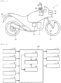
- Fig. 1 is a schematic view illustrating an outline configuration of the motorcycle 1.
- the motorcycle 1 includes the engine 11, a hydraulic pressure control unit 12, a display device 13, a surrounding environment sensor 14, a camera 15, an input device 16, a front-wheel rotational frequency sensor 17, a rear-wheel rotational frequency sensor 18, a license plate 19, and a controller (ECU) 20.
- the motorcycle 1 will also be referred to as an subject vehicle 1.
- the engine 11 corresponds to an example of the drive source of the motorcycle 1 and can output the power for driving the wheel.
- the engine 11 is provided with: one or plural cylinders, each of which is formed with a combustion chamber therein; a fuel injector that injects fuel into the combustion chamber; and an ignition plug.
- a fuel injector that injects fuel into the combustion chamber
- an ignition plug When the fuel is injected from the fuel injector, air-fuel mixture containing air and the fuel is produced in the combustion chamber, and the air-fuel mixture is then ignited by the ignition plug and burned. Consequently, a piston provided in the cylinder reciprocates to cause a crankshaft to rotate.
- a throttle valve is provided to an intake pipe of the engine 11, and an intake air amount for the combustion chamber varies according to a throttle opening amount as an opening degree of the throttle valve.
- the hydraulic pressure control unit 12 is a unit that has a function of controlling a braking force to be generated on the wheel.
- the hydraulic pressure control unit 12 includes components (for example, a control valve and a pump) that are provided to an oil channel connecting a master cylinder and a wheel cylinder and control a brake hydraulic pressure in the wheel cylinder.
- the braking force to be generated on the wheel is controlled by controlling operation of the components in the hydraulic pressure control unit 12.
- the hydraulic pressure control unit 12 may control the braking force to be generated on each of a front wheel and a rear wheel or may only control the braking force to be generated on one of the front wheel and the rear wheel.
- the display device 13 has a display function of visually displaying information. Examples of the display device 13 are a liquid-crystal display and a lamp.
- the surrounding environment sensor 14 detects a surrounding environment information that is information related to an environment around the motorcycle 1. More specifically, the surrounding environment sensor 14 is provided to a front portion of a trunk of the motorcycle 1, and detects the surrounding environment information in front of the subject vehicle 1.
- the surrounding environment information detected by the surrounding environment sensor 14 may be information on a distance to or an orientation of a target object located around the motorcycle 1 (for example, a relative position, a relative distance, a relative speed, relative acceleration, or the like), or may be a characteristic of the target object located around the motorcycle 1 (for example, a type of the target object, a shape of the target object itself, a mark on the target object, or the like).
- Examples of the surrounding environment sensor 14 are a radar, a Lidar sensor, an ultrasonic sensor, and a camera.
- the camera 15 is provided to the front portion of the trunk of the motorcycle 1 and faces the front.
- the camera 15 captures an image in front of the motorcycle 1.
- an imaging direction of the camera 15 is not limited to the front of the motorcycle 1.
- the camera 15 may also function as the surrounding environment sensor 14. In such a case, the function of the camera 15 and the function of the surrounding environment sensor 14 can be implemented by the same device.
- the input device 16 accepts various operations by the rider.
- the input device 16 is provided to a handlebar and includes a push button and the like used for an operation by the rider. Information on the rider's operation using the input device 16 is output to the controller 20.
- the front-wheel rotational frequency sensor 17 is a wheel rotational frequency sensor that detects a rotational frequency of the front wheel (for example, a rotational frequency of the front wheel per unit time [rpm], a travel distance of the front wheel per unit time [km/h], or the like), and outputs a detection result.
- the front-wheel rotational frequency sensor 17 may detect another physical quantity that can substantially be converted to the rotational frequency of the front wheel.
- the front-wheel rotational frequency sensor 17 is provided to the front wheel.
- the rear-wheel rotational frequency sensor 18 is a wheel rotational frequency sensor that detects a rotational frequency of the rear wheel (for example, the rotational frequency of the rear wheel per unit time [rpm], a travel distance of the rear wheel per unit time [km/h], or the like), and outputs a detection result.
- the rear-wheel rotational frequency sensor 18 may detect another physical quantity that can substantially be converted to the rotational frequency of the rear wheel.
- the rear-wheel rotational frequency sensor 18 is provided to the rear wheel.
- the license plate 19 is provided to a rear portion of the trunk of the motorcycle 1.
- the license plate 19 displays an identification number specifically assigned to each vehicle.
- the controller 20 maneuvers the motorcycle 1.
- the controller 20 is partially or entirely constructed of a microcomputer, a microprocessor unit, or the like.
- the controller 20 may partially or entirely be constructed of one whose firmware and the like can be updated, or may partially or entirely be a program module or the like that is executed by a command from a CPU or the like, for example.
- the controller 20 may be provided as one unit or may be divided into multiple units, for example.
- Fig. 2 is a block diagram illustrating an exemplary functional configuration of the controller 20. As illustrated in Fig. 2 , the controller 20 includes an acquisition section 21, an execution section 22, and an identification section 23, for example. In addition, the controller 20 communicates with each device of the motorcycle 1.
- the acquisition section 21 acquires information from each of the devices of the motorcycle 1, and outputs the acquired information to the execution section 22 and the identification section 23.
- the acquisition section 21 acquires the information from the surrounding environment sensor 14, the camera 15, the input device 16, the front-wheel rotational frequency sensor 17, and the rear-wheel rotational frequency sensor 18.
- the acquisition of the information can include extraction, generation, and the like of the information.
- the camera 15 captures an image including another vehicle that is traveling in a group including the subject vehicle 1 in the group ride and outputs the captured image as an image data.
- the acquisition section 21 receives the image data from the camera 15.
- the identification section 23 uses the image data in an identification processing in which the other vehicle is identified.
- the execution section 22 executes various types of control by controlling operation of each of the devices of the motorcycle 1.
- the execution section 22 controls the operation of the engine 11, the hydraulic pressure control unit 12, and the display device 13.
- the execution section 22 can execute an adaptive cruise control.
- the execution section 22 automatically controls a speed of the motorcycle 1 without an acceleration operation or a deceleration operation performed by the rider, i.e., without the rider's operation of an accelerator or a brake.
- the execution section 22 monitors a value of the speed of the motorcycle 1 that is acquired based on the rotational frequency of the front wheel and the rotational frequency of the rear wheel, and can thereby control the speed of the motorcycle 1 to a speed that does not exceed a preset upper-limit speed, for example.
- the execution section 22 executes a distance control to maintain a distance (i.e., an inter-vehicular distance) between the motorcycle 1 and a target vehicle to a target distance.
- the execution section 22 executes the distance control based on the surrounding environment information detected by the surrounding environment sensor 14.
- the surrounding environment sensor 14 can detect a distance between the motorcycle 1 and a preceding vehicle that travels ahead of the motorcycle 1.
- the surrounding environment sensor 14 also can detect a relative speed of the motorcycle 1 with respect to the preceding vehicle.
- the execution section 22 sets the preceding vehicle as the target vehicle and controls the speed of the motorcycle 1 to keep the distance between the motorcycle 1 and the target vehicle at the target distance.
- the distance may be a distance in a direction along a lane (more specifically, a travel lane of the motorcycle 1) or may be a straight-line distance.
- the execution section 22 executes the adaptive cruise control in response to the rider's operation using the input device 16.
- the rider can select a group ride mode as one mode of the adaptive cruise control for the motorcycle 1.
- the execution section 22 executes the group ride mode.
- the group ride mode is selected and executed during the group ride. That is, the group ride mode is one of various modes of the adaptive cruise control that is executed during the group ride.
- the group ride mode is a mode that is particularly suitable for the group ride. For example, in the group ride mode, a short distance is set as the target distance during the distance control.
- the identification section 23 identifies the other vehicle based on the image data capturing the other vehicle that is traveling in the group including the subject vehicle 1.
- the identification section 23 outputs an identification result to the execution section 22.
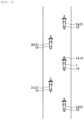
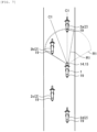
- a group of motorcycles travels while forming at least two convoys. A description will hereinafter be made on an overview of the group ride with reference to Fig. 3 .
- Fig. 3 is a view illustrating a situation where the group of the motorcycles including the motorcycle 1 (i.e., the subject vehicle 1) is traveling during the group ride.
- Fig. 3 illustrates the subject vehicle 1 and other vehicles 2.
- the other vehicles 2 are included in the group of the vehicles and are vehicles other than the subject vehicle 1.
- the other vehicles 2 includes another vehicle 2a, another vehicle 2b and another vehicle 2c.
- the motorcycles travel forming two convoys of a left convoy and a right convoy inside the same travel lane.
- the other vehicle 2b and the other vehicle 2c form the left convoy.
- the other vehicle 2b and the other vehicle 2c are arranged in this order from the front.
- the other vehicle 2a, the subject vehicle 1 and the other vehicle 2d form the right convoy.
- the other vehicle 2a, the subject vehicle 1 and the other vehicle 2d are arranged in this order from the front in a front-rear direction.
- the motorcycles travel such that the motorcycles forming the left convoy and the motorcycles forming the right convoy are alternately arranged in the front-rear direction (that is, in zigzag arrangement).
- the other vehicle 2a in the right convoy, the other vehicle 2b in the left convoy, the subject vehicle 1 in the right convoy, the other vehicle 2c in the left convoy, and the other vehicle 2d in the right convoy are arranged in this order from the front.
- the motorcycles form the zigzag arrangement. Accordingly, a distance between adjacent two motorcycles in the front-rear direction can be shortened as compared to a case where the motorcycles travels forming a single convoy. Thus, it is possible to suppress the group from being divided due to a traffic light.
- the group ride mode is performed, during the group ride, as one modes of the adaptive cruise control.
- the execution section 22 executes the group ride mode based on a travel state information of the other vehicle 2 identified by the identification section 23.
- the identification section 23 identifies the other vehicle 2 based on the image data capturing the other vehicle 2.
- the adaptive cruise control is appropriately executed in the motorcycle 1 during the group ride.
- the travel state information can include various types of information on vehicle travel states.
- the vehicle travel states are, for example, a position, a speed and/or acceleration of a vehicle.
- the identification section 23 identifies the other vehicle 2 based on the image data capturing the other vehicle 2. More specifically, the identification section 23 extracts information which is specific to the other vehicle 2 based on the image data capturing the other vehicle 2.
- the information specific to the other vehicle 2 will be referred to as a vehicle specific information in the present invention.
- the identification section 23 identifies the other vehicle 2 by comparing the vehicle specific information of the other vehicle 2 with a set of group-vehicle specific information about vehicles forming the group. The set of group-vehicle specific information is obtained in advance. Each vehicle of the vehicles in the group has its own group-vehicle specific information.
- the identification section 23 extracts, as the vehicle specific information, information about a candidate vehicle captured in the image data.
- the candidate vehicle is, in other words, a candidate to be identified as the other vehicle 2.
- the identification section 23 identifies the candidate vehicle as the other vehicle 2 when the extracted vehicle specific information about the candidate vehicle corresponds to or similar to the group-vehicle specific information.
- the vehicle specific information is assigned to each vehicle.
- the each vehicle can be recognized based on the vehicle specific information.
- a control flow shown in Fig. 4 an example of using information of the license plate 19 as the vehicle specific information.
- the information of the license plate 19 will be referred to as a license plate information.
- the identification section 23 may execute an identification processing to identify the vehicle 2 by using another vehicle specific information other than the license plate information.
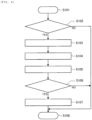
- Fig. 4 is a flowchart illustrating an example of a processing procedure that is related to the group ride and is executed by the controller 20.
- the control flow illustrated in Fig. 4 is repeatedly executed at a time interval, which is set in advance, for example.
- Step S101 in Fig. 4 corresponds to initiation of the control flow illustrated in Fig. 4 .
- Step S108 in Fig. 4 corresponds to termination of the control flow illustrated in Fig. 4 .
- step S102 the controller 20 determines whether the group ride mode is currently executed. If it is determined that the group ride mode is currently executed (step S102/YES), the processing proceeds to step S103. On the other hand, if it is determined that the group ride mode is not currently executed (step S102/NO), the control flow illustrated in Fig. 4 is terminated.
- step S103 the acquisition section 21 of the controller 20 acquires the image data based on the output result of the camera 15. In this way, the acquisition section 21 can acquire the image data capturing the other vehicle 2 based on the output result of the camera 15.
- step S103 the acquisition section 21 acquires the image data regardless of whether the other vehicle 2 is captured in the image data acquired by the camera 15.
- the other vehicle 2 is captured in the acquired image data.
- the other vehicle 2 is not located within the field of view of the camera 15, the other vehicle 2 is not captured in the acquired image data.
- the vehicle captured in the image data is merely the candidate vehicle (i.e., the candidate for the other vehicle 2).
- the vehicle captured in the image data is possibly the other vehicle 2 or is possibly a vehicle outside the group.
- step S104 the identification section 23 of the controller 20 extracts, as the vehicle specific information, the license plate information of the vehicle that is captured in the image data based on the image data acquired in step S103.
- the identification section 23 extracts the candidate vehicle from the image data acquired in step S103, and then extracts the license plate information from an area of the image data where the candidate vehicle is captured.
- the license plate information is information on the identification number that is displayed on the license plate 19.
- the identification section 23 can recognize the identification number that is displayed on the license plate 19 of the candidate vehicle captured in the image data. More specifically, the identification section 23 can recognize the identification number on the license plate 19 that is captured in the image data by using a method such as pattern matching processing.
- step S105 the identification section 23 of the controller 20 executes the identification processing to identify the other vehicle 2.
- the identification section 23 identifies the other vehicle 2 by comparing the license plate information that is extracted in step S104 (that is, the vehicle specific information) to the license plate information of each of the vehicles forming the group that is acquired in advance.
- the group-vehicle specific information is the license plate information.
- the acquisition section 21 acquires, as the group-vehicle specific information, the license plate information of each of the vehicles in the group.
- the rider of the subject vehicle 1 may store information by a setting operation, and the acquisition section 21 acquires, as the group-vehicle specific information, the license plate information of each of the vehicles in the group based on the information stored by the rider.
- the setting operation is an operation to set various types of the information, and is accepted by the input device 16, for example.
- the rider uses the input device 16 to enter the information on the identification number on the license plate 19 of each of the vehicles in the group.
- the thus-entered information is stored as the group-vehicle specific information in a storage element of the controller 20.
- An input screen that accepts the setting operation may be displayed on the display device 13, and the setting operation may be performed by using the input screen.
- the setting operation may be performed by using a worn article by the rider (for example, a helmet or the like) or a wireless terminal carried by the rider (for example, a smartphone or the like) instead of the input device 16 mounted to the motorcycle 1.
- the setting operation may be an operation performed by the rider's finger or may be an operation by voice input.
- the identification section 23 identifies the vehicle captured in the image data as the other vehicle 2.
- the license plate information extracted from the image data is only a part of the identification number on the license plate 19 that is captured in the image data.
- the number of digits of the identification number indicated by the extracted license plate information is smaller than the number of digits of the identification number actually displayed on the license plate 19.
- the identification section 23 may identify the vehicle captured in the image data as the other vehicle 2.
- the license plate information of each of the vehicles in the group is acquired as the group-vehicle specific information based on the information on the setting operation by the rider of the subject vehicle 1.
- the acquisition section 21 may automatically acquire, as the group-vehicle specific information, the license plate information of each of the vehicles in the group regardless of the setting operation by the rider of the subject vehicle 1.
- the acquisition section 21 extracts the license plate information from the image data that is acquired by the camera 15 during the travel. Then, in the case where the same license plate information is continuously extracted for or over a specified period, the acquisition section 21 acquires such license plate information as the group-vehicle specific information. In this way, the group-vehicle specific information may automatically be acquired and constructed.
- step S106 the controller 20 determines whether the other vehicle 2 is identified by the identification section 23. If it is determined that the other vehicle 2 is identified by the identification section 23 (step S106/YES), the processing proceeds to step S107. On the other hand, if it is determined that the other vehicle 2 is not identified by the identification section 23 (step S106/NO), the control flow illustrated in Fig. 4 is terminated.
- step S107 the execution section 22 of the controller 20 executes the group ride mode based on the travel state information of the other vehicle 2 identified by the identification section 23, and the control flow illustrated in Fig. 4 is terminated.
- the other vehicle 2 is identified by the identification section 23 based on the image data capturing the other vehicle 2.
- the acquisition section 21 can acquire the travel state information of the other vehicle 2 identified by the identification section 23 based on the output result of the surrounding environment sensor 14.
- the execution section 22 can execute the group ride mode based on the travel state information of the other vehicle 2 identified by the identification section 23.
- the vehicle outside the group is possibly identified as the other vehicle 2.
- the other vehicle 2 since the other vehicle 2 is identified based on the image data that is acquired by the camera 15, the other vehicle 2 can appropriately be identified. Therefore, in the case where the group ride is made, the group ride mode can appropriately be executed according to a traffic condition around the subject vehicle 1.
- the execution section 22 preferably executes the group ride mode based on the travel state information of the plural other vehicles 2.
- the execution section 22 executes the distance control based on the travel state information of the plural other vehicles 2.
- a description will hereinafter be made on an example in which the distance control is executed based on the travel state information of the plural other vehicles 2.
- the convoy in which the subject vehicle 1 is located in the group will also be referred to as a subject convoy.
- the other vehicles 2 in the subject convoy (the other vehicle 2a and the other vehicle 2d in the example illustrated in Fig. 3 ) will also be referred to as subject-convoy vehicles.
- a convoy other than the subject convoy will also be referred to as another convoy.
- the other vehicles 2 in the other convoy (the other vehicle 2b and the other vehicle 2c in the example illustrated in Fig. 3 ) will also be referred to as other-convoy vehicles.
- the execution section 22 can distinguish the subject-convoy vehicle and the other-convoy vehicle from each other based on the relative position of the other vehicle 2, which is identified by the identification section 23, with respect to the subject vehicle 1.
- the execution section 22 may set the target vehicle for the distance control based on the travel state information of the other vehicle 2 identified by the identification section 23. For example, during the group ride mode, the execution section 22 may set the subject-convoy vehicle as the target vehicle for the distance control and, under a particular situation, may switch the target vehicle from the subject-convoy vehicle to the other-convoy vehicle. A description will hereinafter be made on an example of a situation where the target vehicle is switched with reference to Fig. 5 and Fig. 6 .
- Fig. 5 is a view illustrating a situation where the group including the motorcycle 1 (i.e., the subject vehicle 1) travels straight.
- the subject vehicle 1 and the other vehicles 2a, 2b, 2c, 2d travel on a straight road in the same arrangement as that in Fig. 3 .
- the straight road is a travel road having a curvature radius that is large to such an extent of not affecting a driving operation of the motorcycle 1.
- the subject convoy is the right convoy, and the other convoy is the left convoy.
- the other vehicles 2a, 2d correspond to the subject-convoy vehicles, and the other vehicles 2b, 2c correspond to the other-convoy vehicles.
- the execution section 22 sets the other vehicle 2a as the target vehicle of the distance control.
- the other vehicle 2a is included in the subject-convoy vehicles located in front of the subject vehicle 1 and is closest to the subject vehicle among the subject-convoy vehicles located in front of the subject vehicle 1. According to this example, a distance between the subject vehicle 1 and the other vehicle 2a is kept at the target distance.
- the execution section sets the other-convoy vehicle as the target vehicle of the distance control.
- the execution section 22 switches the target vehicle from the other vehicle 2a to the other vehicle 2b when a distance D1 between the subject vehicle 1 and the other vehicle 2b.
- the other vehicle 2b is one of preceding other-convoy vehicles located in front of the subject vehicle 1 and is closest to the subject vehicle 1 among the preceding other-convoy vehicles.
- the lower limit distance is set to a distance, e.g., at which the subject vehicle 1 approaches to the other vehicle 2b and possibly passes through the other vehicle 2b.
- the distance D1 between the subject vehicle 1 and the other vehicle 2b is maintained to the target distance. More specifically, during the distance control, the execution section 22 controls the speed of the subject vehicle 1 based on the distance D1 and a relative speed of the subject vehicle 1 with respect to the other vehicle 2b. As a result, the subject vehicle 1 is suppressed from passing through the other vehicle 2b. Thus, the state where the group including the subject vehicle 1 travels in the zigzag arrangement is maintained.
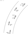
- Fig. 6 is a view illustrating a situation where the motorcycle 1 (i.e., the subject vehicle 1) is traveling in the group during the group ride and is turning a curve.
- the subject vehicle 1 and the other vehicles 2a, 2b, 2c, 2d are traveling on a curved road in the same arrangement as that in Fig. 3 .
- the curved road is a travel road having a curvature radius that is small to such an extent of affecting the driving operation of the motorcycle 1.
- the subject convoy is the right convoy, and the other convoy is the left convoy.
- the other vehicles 2a, 2d correspond to the subject-convoy vehicles, and the other vehicles 2b, 2c correspond to the other-convoy vehicles.
- the execution section 22 sets the other-convoy vehicle as the target vehicle of the distance control.
- the execution section 22 sets the other vehicle 2b as the target vehicle.
- the other vehicle 2b is one of preceding other-convoy vehicles located in front of the subject vehicle 1 and is closest to the subject vehicle 1 among the preceding other-convoy vehicles. That is, the target vehicle is switched from the other vehicle 2a to the other vehicle 2b.
- the execution section 22 determines whether the subject vehicle 1 is traveling the curve. Then, when determining that the subject vehicle 1 is traveling the curve, the execution section 22 can consider that the group including the subject vehicle 1 is traveling the curve. The determination on whether the subject vehicle 1 is traveling the curve can be made by using an inertial measurement unit (IMU), a car navigation system, or the like, for example.
- IMU inertial measurement unit
- a car navigation system or the like, for example.
- a distance between each adjacent two vehicles when the group including the subject vehicle 1 is turning a curve tends to be long as compared to a distance between each adjacent two vehicles when the group is traveling straight.
- the other vehicle 2a may go away from the subject vehicle 1 and the surrounding environment sensor 14 may not be able to detect the other vehicle 2a. Therefore, the other vehicle 2b is set as the target vehicle to avoid a situation where no vehicle is set as the target vehicle.
- the target distance for the distance control while the group of vehicles including the subject vehicle 1 is turning a curve is preferably increased as compared to the target distance for the distance control while the group of vehicles is traveling straight.
- a distance between adjacent two vehicles in the group while the group of the vehicles is turning a curve is preferable increased as compared to a distance between adjacent two vehicles in the group while the group of the vehicles is traveling straight.
- the execution section 22 may set the target distance for the distance control based on the travel state information of the other vehicle 2 identified by the identification section 23.
- the execution section 22 may change the target distance for the distance control based on the relative position of the other vehicle 2, which is identified by the identification section 23, to the subject vehicle 1.
- the execution section 22 may change the target distance according to a distance between the subject vehicle 1 and the other-convoy vehicle along a vehicle width direction. For example, according to the example illustrated in Fig. 3 , when the other vehicle 2a is set as the target vehicle of the distance control, the execution section 22 may increase the target distance as the distance between the subject vehicle 1 and the other-convoy vehicle along the vehicle width direction becomes short.
- the target distance is set to a target value of a distance between the subject vehicle 1 and the other vehicle 2a.
- the camera 15 may be used to identify the other vehicle 2.
- the camera 15 can capture an image behind the motorcycle 1.
- the identification section 23 can also identify the other vehicle 2, which is located behind the subject vehicle 1, based on the image data acquired by the camera 15.
- the execution section 22 may change the target distance based on the distance between the subject vehicle 1 and the other vehicle 2 located behind the subject vehicle 1.
- the execution section 22 may increase the target distance between the subject vehicle 1 and the other vehicle 2b as the distance between the subject vehicle 1 and the other vehicle 2c increases.
- the target distance is, in other words, a target value for a distance between the subject vehicle 1 and the other vehicle 2b. Accordingly, a distance between adjacent two vehicles in the group can be uniformed, and therefore the formation of the group including the subject vehicle 1 can be easily maintained to the zigzag arrangement.
- the execution section 22 may change the target distance of the distance control based on a positional relationship between the other vehicles 2 identified by the identification section 23. More specifically, the execution section 22 may set the target distance of the distance control based on a distance between adjacent two vehicles of the other vehicles 2. According to the example illustrated in Fig. 3 , when the other vehicle 2a is set as the target vehicle of the distance control, the execution section 22 may set the target distance between the subject vehicle 1 and the other vehicle 2a so that the target distance is close to a distance between the other vehicle 2b and one vehicle (not shown) of preceding left-convoy vehicles 2 located in front of the other vehicle 2b in the left convoy. As a result, it is possible to make a distance between each adjacent two vehicles in the group. Thus, the formation of the group including the subject vehicle 1 can be easily maintained to the zigzag arrangement.
- the execution section 22 may execute the group ride mode based on the travel state information of the plural other vehicles 2.
- the execution section 22 may set one of the other vehicle 2a and the other vehicle 2b as the target vehicle for the distance control.
- the execution section 22 may execute processing other than the distance control based on the travel state information of the other vehicle 2 identified by the identification section 23.
- the execution section 22 may change a detection range of the surrounding environment information used for the adaptive cruise control based on the relative position of the other vehicle 2, which is identified by the identification section 23, with respect to the subject vehicle 1. More specifically, the execution section 22 determines whether the subject-convoy is the left convoy or the right convoy based on the relative position of the other vehicle 2 with respect to the subject vehicle 1. Then, based on the determination result of the determination whether the subject convoy is the left convoy or the right convoy, the execution section 22 changes the detection range of the surrounding environment information detected by the surrounding environment sensor 14.
- Fig. 7 is a view illustrating a situation where the detection range of the surrounding environment information, which is used for the adaptive cruise control executed by the motorcycle 1, is changed.
- a detection range R1 of the surrounding environment sensor 14 before the change is indicated by broken lines
- the detection range R1 after the change is indicated by solid lines.
- the detection range R1 of the surrounding environment sensor 14 expands radially to the front from a front portion of the motorcycle 1.
- the surrounding environment sensor 14 can detect the surrounding environment information within the detection range R1. That is, the detection range of the surrounding environment information detected by the surrounding environment sensor 14 basically matches the detection range R1 of the surrounding environment sensor 14. However, as will be described below, the detection range of the surrounding environment information detected by the surrounding environment sensor 14 can be changed without changing the detection range R1 of the surrounding environment sensor 14. Thus, these ranges will be distinguished from each other for the description.
- the execution section 22 changes the detection range R1 of the surrounding environment sensor 14, and thereby changes the detection range of the surrounding environment information detected by the surrounding environment sensor 14. More specifically, the execution section 22 places a center C1 of the detection range R1 of the surrounding environment sensor 14 on a side of a travel path of the subject vehicle 1 where the other-convoy vehicle is located.
- the center C1 of the detection range R1 may be, e.g., a center axis of a range expanding radially.
- a center of the detection range of the surrounding environment information detected by the surrounding environment sensor 14 is located on the side of the travel path of the subject vehicle 1 where the other-convoy vehicle is located.
- the center C1 of the detection range R1 is located on the travel path of the subject vehicle 1 as indicated by a broken line.
- the other vehicle 2b is identified by the identification section 23, and the execution section 22 determines that the subject convoy is the right convoy based on the relative position of the other vehicle 2b with respect to the subject vehicle 1.
- the execution section 22 places the center C1 of the detection range R1 of the surrounding environment sensor 14 on the left side of the travel path of the subject vehicle 1, i.e., on the side where the other vehicles 2b, 2c as the other-convoy vehicles are located.
- the center of the detection range of the surrounding environment information detected by the surrounding environment sensor 14 is located on the left side of the travel path of the subject vehicle 1.
- the detection range R1 of the surrounding environment sensor 14 can be placed within the travel lane of the subject vehicle 1.
- the detection range R1 of the surrounding environment sensor 14 is, in other words, the detection range of the surrounding environment information detected by the surrounding environment sensor 14.
- an unexpected vehicle is set as the target vehicle of the distance control, e.g., when the unexpected vehicle comes into the detection range R1.
- the unexpected vehicle may be a vehicle traveling in an adjacent travel lane which is located adjacent to the subject lane in which the subject vehicle 1 is traveling.
- the execution section 22 may change the detection range of the surrounding environment information detected by the surrounding environment sensor 14 without changing the detection range R1 of the surrounding environment sensor 14.
- the execution section 22 may change the detection range of the surrounding environment information by not detecting, as the surrounding environment information, information on a particular range (for example, in the example illustrated in Fig. 7 , a right range with the swept path of the subject vehicle 1 being the reference) within the detection range R1.
- the license plate information is used as the vehicle specific information.
- the identification section 23 may execute the identification processing to identify the other vehicle 2 by using the vehicle specific information other than the license plate information.
- information other than the license plate information may be used as the vehicle specific information.
- the vehicle specific information may include information about a shape (hereinafter also referred to as a shape information).
- the shape information is information on a shape of a vehicle body or a shape of the rider, for example.
- the Information on the shape of the rider can include information on the worn article by the rider in addition to the shape of the rider himself/herself.
- the identification section 23 executes the image processing on the acquired image data so as to extract the shape information of the vehicle captured in the image data as the vehicle specific information. Then, the identification section 23 identifies the other vehicle 2 by comparing the shape information extracted from the image data to the shape information of each of the vehicles in the group that is acquired in advance as the group-vehicle specific information. More specifically, in the case where the shape information extracted from the image data matches or is similar to any piece of the shape information of the vehicles in the group that is acquired in advance as the group-vehicle specific information, the identification section 23 identifies the vehicle captured in the image data as the other vehicle 2.
- the vehicle specific information may include information on a color (hereinafter also referred to as color information).
- the color information is information on a color of the vehicle body or a color of the rider, for example.
- the Information on the color of the rider can include information on a color of the worn article by the rider in addition to the color of the rider himself/herself.
- the color information can also include information on a color combination (for example, information on a combination of the color of the vehicle body and the color of the worn article by the rider, or the like).
- the identification section 23 executes the image processing on the acquired image data so as to extract the color information of the vehicle captured in the image data as the vehicle specific information. Then, the identification section 23 identifies the other vehicle 2 by comparing the color information extracted from the image data to the color information of each of the vehicles in the group that is acquired in advance as the group-vehicle specific information. More specifically, in the case where the color information extracted from the image data matches or is similar to any piece of the color information of the vehicles in the group that is acquired in advance as the group-vehicle specific information, the identification section 23 identifies the vehicle captured in the image data as the other vehicle 2.
- the vehicle specific information may include information on a pattern (hereinafter also referred to as pattern information).
- pattern information is information on a pattern of the vehicle body or a pattern of the rider, for example.
- the Information on the pattern of the rider can include information on a pattern of the worn article by the rider in addition to the pattern of the rider himself/herself.
- the identification section 23 executes the image processing on the acquired image data so as to extract the pattern information of the vehicle captured in the image data as the vehicle specific information. Then, the identification section 23 identifies the other vehicle 2 by comparing the pattern information extracted from the image data to the pattern information of each of the vehicles in the group that is acquired in advance as the group-vehicle specific information. More specifically, in the case where the pattern information extracted from the image data matches or is similar to any piece of the pattern information of the vehicles in the group that is acquired in advance as the group-vehicle specific information, the identification section 23 identifies the vehicle captured in the image data as the other vehicle 2.
- the vehicle specific information may include information on a dimension (hereinafter also referred to as dimension information).
- dimension information is information on a dimension of the vehicle and, for example, can include information on a dimension ratio between a height direction and a width direction of the vehicle body, information on a dimension ratio between the vehicle body and the rider, or the like.
- the identification section 23 executes the image processing on the acquired image data so as to extract the dimension information of the vehicle captured in the image data as the vehicle specific information. Then, the identification section 23 identifies the other vehicle 2 by comparing the dimension information extracted from the image data to the dimension information of each of the vehicles in the group that is acquired in advance as the group-vehicle specific information. More specifically, in the case where the dimension information extracted from the image data matches or is similar to any piece of the dimension information of the vehicles in the group that is acquired in advance as the group-vehicle specific information, the identification section 23 identifies the vehicle captured in the image data as the other vehicle 2.
- the identification section 23 can extract the vehicle specific information from the image data that is acquired by the camera 15 capturing the image behind or on a side of the motorcycle 1.
- the camera 15 may capture the image behind or on the side of the motorcycle 1.
- the camera 15 that captures the image behind the motorcycle 1 may be provided to the motorcycle 1.
- the camera 15 that captures the image on the side of the motorcycle 1 may be provided to the motorcycle 1.
- the identification section 23 may use only one type of the vehicle specific information or may use plural types of the vehicle specific information. However, from a perspective of identifying the other vehicle 2 with a high degree of accuracy, the identification section 23 preferably executes the identification processing of the other vehicle 2 by using the plural types of the vehicle specific information.
- the identification section 23 identifies the vehicle captured in the image data as the other vehicle 2.
- the identification section 23 may set the type of the vehicle specific information used to identify the other vehicle 2 according to a combination of the motorcycles constituting the group.
- the other vehicle 2 can be identified with the higher degree of accuracy by using the license plate information as the vehicle specific information than by using the shape information, the color information, the pattern information, or the dimension information as the vehicle specific information.
- the identification section 23 sets the type of the vehicle specific information used to identify the other vehicle 2 to the license plate information, for example.
- the identification section 23 sets the type of the vehicle specific information used to identify the other vehicle 2 to the color information. In this way, the other vehicle 2 can be identified with the high degree of accuracy.
- the identification section 23 can automatically set the type of the vehicle specific information used to identify the other vehicle 2 according to a combination of the motorcycles constituting the group.
- the identification section 23 uses the image data acquired by the camera 15 during the travel, and extracts a characteristic (for example, the shape, the color, the pattern, the dimension, or the like) of the vehicle that is assumed as the other vehicle 2 constituting the group.
- the vehicle that is assumed as the other vehicle 2 may be the vehicle that is identified as the other vehicle 2 by the above-described identification processing, or may be a vehicle that is continuously captured in the image data for or over a specified period. Then, by using an extraction result of the characteristic of the vehicle that is assumed as the other vehicle 2, the identification section 23 can set the type of the vehicle specific information used to identify the other vehicle 2 according to the combination of the motorcycles constituting the group.
- step S103 onward if it is determined that the group ride mode is currently executed (step S102/YES), the processing in step S103 onward is executed.
- an execution condition of the processing in step S103 onward is not limited to that in this example.
- the above execution condition only needs to be a condition with which it is possible to determine that the group including the subject vehicle 1 and the other vehicles 2 makes the group ride.
- the above execution condition may be such a condition that it is determined that the subject vehicle 1 and the other vehicles 2 travel in the zigzag arrangement, or the like.
- the controller 20 acquires the information on the positional relationships between the subject vehicle 1 and the other vehicles 2 via wireless communication with the other vehicles 2 or an infrastructure facility, and can thereby determine whether the subject vehicle 1 and the other vehicles 2 travel in the zigzag arrangement by using such information.
- the execution section 22 executes the group ride mode, which is the mode of the adaptive cruise control executed during the group ride, based on the travel state information of the other vehicle 2 identified by the identification section 23.
- the identification section 23 identifies the other vehicle 2 based on the image data capturing the other vehicle 2. In this way, for example, compared to the case where it is attempted to identify the other vehicle 2 based on the surrounding environment information acquired by the radar, the other vehicle 2 can appropriately be identified.
- the group ride mode can appropriately be executed according to the traffic condition around the subject vehicle 1. Therefore, it is possible to appropriately execute the adaptive cruise control of the motorcycle 1 in the group ride.
- the execution section 22 executes the group ride mode based on the travel state information of the plural other vehicles 2. In this way, it is possible to execute the group ride mode by using larger pieces of the information on the traffic condition around the subject vehicle 1. Therefore, the group ride mode can further appropriately be executed according to the traffic condition around the subject vehicle 1.
- the execution section 22 executes the distance control based on the travel state information of the plural other vehicles 2 in the group ride mode. In this way, it is possible to execute the distance control in the group ride mode by using the larger pieces of the information on the traffic condition around the subject vehicle 1. Therefore, the distance control in the group ride mode can appropriately be executed according to the traffic condition around the subject vehicle 1.
- the identification section 23 extracts the vehicle specific information of the other vehicle 2 as the vehicle specific information based on the image data capturing the other vehicle 2. Then, by comparing the extracted vehicle specific information to the group-vehicle specific information as the vehicle specific information of the vehicle in the group that is acquired in advance, the identification section 23 identifies the other vehicle 2. In this way, the other vehicle 2 is appropriately identified by using the image data that is acquired by the camera 15.
- the vehicle specific information includes the information on the license plate 19 (that is, the license plate information).
- the other vehicle 2 is further appropriately identified by using the image data acquired by the camera 15.
- the vehicle specific information includes the information on the shape (that is, the shape information).
- the other vehicle 2 is further appropriately identified by using the image data acquired by the camera 15.
- the vehicle specific information includes the information on the color (that is, the color information).
- the other vehicle 2 is further appropriately identified by using the image data acquired by the camera 15.
- the vehicle specific information includes the information on the pattern (that is, the pattern information).
- the other vehicle 2 is further appropriately identified by using the image data acquired by the camera 15.
- the vehicle specific information includes the information on the dimension (that is, the dimension information).
- the other vehicle 2 is further appropriately identified by using the image data acquired by the camera 15.
- the identification section 23 sets the type of the vehicle specific information used to identify the other vehicle 2 according to the combination of the motorcycles constituting the group. In this way, the other vehicle 2 can be identified with the higher degree of accuracy.
- the identification section 23 of the controller 20 automatically sets the type of the vehicle specific information according to the combination of the motorcycles traveling in the group.
- the identification section 23 automatically sets the type of the vehicle specific information regardless of the setting operation performed by the rider. In this way, it is possible to easily and appropriately set the type of the vehicle specific information used to identify the other vehicle 2.
- the acquisition section 21 acquires the group-vehicle specific information based on the information on the setting operation by the rider. In this way, the group-vehicle specific information can be acquired neither excessively or deficiently.
- the acquisition section 21 of the controller 20 automatically acquires the group-vehicle specific information regardless of the setting operation performed by the rider. In this way, the group-vehicle specific information can easily be acquired.
Landscapes
- Engineering & Computer Science (AREA)
- Automation & Control Theory (AREA)
- Transportation (AREA)
- Mechanical Engineering (AREA)
- Physics & Mathematics (AREA)
- General Physics & Mathematics (AREA)
- Multimedia (AREA)
- Theoretical Computer Science (AREA)
- Traffic Control Systems (AREA)
Claims (13)
- Steuerung (20) zum Manövrieren eines Motorrads (1), wobei die Steuerung Folgendes umfassteinen Ausführungsabschnitt (22), der dazu ausgelegt ist, eine adaptive Geschwindigkeitsregelung auf Basis von Informationen zu einer umliegenden Umgebung des Motorrads (1) auszuführen, wobei der Ausführungsabschnitt (22) in der adaptiven Geschwindigkeitsregelung dazu ausgelegt ist, eine Geschwindigkeit des Motorrads (1) automatisch ohne eine Beschleunigungsoperation oder eine Verzögerungsoperation durch einen Fahrer des Motorrads (1) zu steuern, um einen Abstand zwischen dem Motorrad (1) und einem Zielfahrzeug auf einem Zielabstand zu halten, wobeidie Steuerung (20) ferner Folgendes umfasst:einen Erfassungsabschnitt (21), der dazu ausgelegt ist, auf Basis eines Detektionsergebnisses, das von einer Kamera (15) ausgegeben wird, die an einem Testfahrzeug (1) montiert ist, Bilddaten zu erfassen, wobei die Bilddaten, die ein anderes Fahrzeug (2) erfassen, das in einer Gruppenfahrt fährt, bei der eine Gruppe von Motorrädern, die das Testfahrzeug (1) und das andere Fahrzeug (2) beinhalten, in einer Gruppe fährt; undeinen Identifikationsabschnitt (23), der dazu ausgelegt ist, das andere Fahrzeug (2) auf Basis der vom Erfassungsabschnitt (21) erfassten Bilddaten zu identifizieren, undder Ausführungsabschnitt (22) dazu ausgelegt ist, einen Gruppenfahrtmodus, bei dem es sich um einen Modus der adaptiven Geschwindigkeitsregelung handelt und der während der Gruppenfahrt auf Basis von Fahrzustandsinformationen des anderen Fahrzeugs (2), das vom Identifikationsabschnitt (23) identifiziert wird, ausgeführt wird, wobeider Identifikationsabschnitt (23) zu Folgendem ausgelegt ist:Extrahieren von Informationen, die sich spezifisch auf das andere Fahrzeug (2) beziehen, auf Basis der Bilddaten als fahrzeugspezifische Informationen undIdentifizieren des anderen Fahrzeugs (2) durch Vergleichen der fahrzeugspezifischen Informationen mit gruppenfahrzeugspezifischen Informationen, bei denen es sich um Informationen handelt, die sich spezifisch auf Fahrzeuge beziehen, die in der Gruppe beinhaltet sind, und die vorab erhalten werden.
- Steuerung nach Anspruch 1, wobei
der Ausführungsabschnitt (22) dazu ausgelegt ist, den Gruppenfahrtmodus auf Basis der Fahrzustandsinformationen oder einer Mehrzahl von anderen Fahrzeugen (2) auszuführen. - Steuerung nach Anspruch 2, wobei
der Ausführungsabschnitt (22) während des Gruppenfahrtmodus dazu ausgelegt ist, die Abstandssteuerung auf Basis der Fahrzustandsinformationen oder der Mehrzahl von anderen Fahrzeugen (2) auszuführen. - Steuerung nach einem der Ansprüche 1 bis 3, wobei
die fahrzeugspezifischen Informationen Informationen über ein Nummernschild (19) beinhalten. - Steuerung nach einem der Ansprüche 1 bis 4, wobei
die fahrzeugspezifischen Informationen Informationen über eine Form beinhalten. - Steuerung nach einem der Ansprüche 1 bis 5, wobei
die fahrzeugspezifischen Informationen Informationen über eine Farbe beinhalten. - Steuerung nach einem der Ansprüche 1 bis 6, wobei
die fahrzeugspezifischen Informationen Informationen über ein Muster beinhalten. - Steuerung nach einem der Ansprüche 1 bis 7, wobei
die fahrzeugspezifischen Informationen Informationen über eine Dimension beinhalten. - Steuerung nach einem der Ansprüche 1 bis 8, wobei
der Identifikationsabschnitt (23) dazu ausgelegt ist, eine Art der fahrzeugspezifischen Informationen einzustellen, die verwendet werden, um das andere Fahrzeug (2) gemäß einer Kombination von Motorrädern, die in der Gruppe beinhaltet sind, zu identifizieren. - Steuerung nach Anspruch 9, wobei
der Identifikationsabschnitt (23) dazu ausgelegt ist, die Art der fahrzeugspezifischen Informationen automatisch einzustellen, die verwendet werden, um das andere Fahrzeug (2) gemäß der Kombination der Motorräder, die die Gruppe konstituieren, unabhängig von einer Einstellungsoperation, die vom Fahrer durchgeführt wird, zu identifizieren. - Steuerung nach einem der Ansprüche 1 bis 10, wobei
der Erfassungsabschnitt (21) dazu ausgelegt ist, die gruppenfahrzeugspezifischen Informationen auf Basis von Informationen zu erfassen, die von einer Einstellungsoperation eingegeben werden, die vom Fahrer durchgeführt wird. - Steuerung nach einem der Ansprüche 1 bis 10, wobei
der Erfassungsabschnitt (21) dazu ausgelegt ist, die gruppenfahrzeugspezifischen Informationen unabhängig von einer Einstellungsoperation des Fahrers automatisch zu erfassen. - Steuerverfahren zum Manövrieren eines Motorrads (1), wobei das Steuerverfahren Folgendes umfasstAusführen einer adaptiven Geschwindigkeitsregelung auf Basis von Informationen zu einer umliegenden Umgebung des Motorrads (1) unter Verwendung eines Ausführungsabschnitts (22) einer Steuerung (20), wobei der Ausführungsabschnitt (22) in der adaptiven Geschwindigkeitsregelung dazu ausgelegt ist, eine Geschwindigkeit des Motorrads (1) automatisch ohne eine Beschleunigungsoperation oder eine Verzögerungsoperation durch einen Fahrer des Motorrads (1) zu steuern, um einen Abstand zwischen dem Motorrad (1) und einem Zielfahrzeug auf einem Zielabstand zu halten, wobeidas Steuerverfahren ferner Folgendes umfasst:Erfassen von Bilddaten auf Basis eines Detektionsergebnisses, das von einer Kamera (15) ausgegeben wird, die an einem Testfahrzeug (1) montiert ist, unter Verwendung eines Erfassungsabschnitts (21) der Steuerung (20), wobei die Bilddaten, die ein anderes Fahrzeug (2) erfassen, das in einer Gruppenfahrt fährt, bei der eine Gruppe von Motorrädern, die das Testfahrzeug (1) und das andere Fahrzeug (1) beinhalten, in einer Gruppe fährt; undIdentifizieren des anderen Fahrzeugs (2) auf Basis der vom Erfassungsabschnitt (21) erfassten Bilddaten unter Verwendung eines Identifikationsabschnitts (23) der Steuerung (20), undder Ausführungsabschnitt (22) einen Gruppenfahrtmodus ausführt, bei dem es sich um einen Modus der adaptiven Geschwindigkeitsregelung handelt, und der während der Gruppenfahrt auf Basis von Fahrzustandsinformationen des anderen Fahrzeugs (2), das vom Identifikationsabschnitt (23) identifiziert wird, ausgeführt wird, wobeidas Steuerverfahren ferner Folgendes umfasst:Extrahieren von Informationen, die sich spezifisch auf das andere Fahrzeug (2) beziehen, unter Verwendung des Identifikationsabschnitts (23) der Steuerung (20) auf Basis der Bilddaten undIdentifizieren des anderen Fahrzeugs (2) unter Verwendung des Identifikationsabschnitts (23) der Steuerung (20) durch Vergleichen der fahrzeugspezifischen Informationen mit gruppenfahrzeugspezifischen Informationen, bei denen es sich um Informationen handelt, die sich spezifisch auf Fahrzeuge beziehen, die in der Gruppe beinhaltet sind, und die vorab erhalten werden.
Applications Claiming Priority (2)
| Application Number | Priority Date | Filing Date | Title |
|---|---|---|---|
| JP2021076948 | 2021-04-29 | ||
| PCT/IB2022/053667 WO2022229791A1 (ja) | 2021-04-29 | 2022-04-20 | 制御装置及び制御方法 |
Publications (2)
| Publication Number | Publication Date |
|---|---|
| EP4331933A1 EP4331933A1 (de) | 2024-03-06 |
| EP4331933B1 true EP4331933B1 (de) | 2025-06-11 |
Family
ID=81580618
Family Applications (1)
| Application Number | Title | Priority Date | Filing Date |
|---|---|---|---|
| EP22721473.1A Active EP4331933B1 (de) | 2021-04-29 | 2022-04-20 | Steuerungsvorrichtung und steuerungsverfahren |
Country Status (5)
| Country | Link |
|---|---|
| US (1) | US20240208509A1 (de) |
| EP (1) | EP4331933B1 (de) |
| JP (1) | JP7650350B2 (de) |
| CN (1) | CN117241977A (de) |
| WO (1) | WO2022229791A1 (de) |
Families Citing this family (2)
| Publication number | Priority date | Publication date | Assignee | Title |
|---|---|---|---|---|
| JP7592115B2 (ja) * | 2023-03-24 | 2024-11-29 | 本田技研工業株式会社 | 車両制御装置、車両制御装置の動作方法、プログラム及び記憶媒体 |
| WO2025046351A1 (ja) * | 2023-08-30 | 2025-03-06 | ロベルト•ボッシュ•ゲゼルシャフト•ミト•ベシュレンクテル•ハフツング | ライダー支援システムの制御装置及び制御方法 |
Family Cites Families (21)
| Publication number | Priority date | Publication date | Assignee | Title |
|---|---|---|---|---|
| EP2836795B1 (de) * | 2012-04-14 | 2018-03-14 | Audi AG | Verfahren, system und fahrzeug zum durchführen einer gruppenfahrt |
| DE112014005122T5 (de) * | 2013-11-08 | 2016-08-11 | Honda Motor Co., Ltd. | Kolonnenfahrt-Steuervorrichtung |
| WO2015068501A1 (ja) * | 2013-11-08 | 2015-05-14 | 本田技研工業株式会社 | 隊列走行制御装置 |
| JP6032220B2 (ja) * | 2014-02-07 | 2016-11-24 | トヨタ自動車株式会社 | 車両制御装置、及び、車両制御システム |
| KR20170016177A (ko) * | 2015-08-03 | 2017-02-13 | 엘지전자 주식회사 | 차량 및 그 제어방법 |
| EP3335955B1 (de) * | 2015-08-17 | 2020-07-08 | Yamaha Hatsudoki Kabushiki Kaisha | Neigefahrzeug |
| JP6443318B2 (ja) | 2015-12-17 | 2018-12-26 | 株式会社デンソー | 物体検出装置 |
| JP6617628B2 (ja) * | 2016-03-18 | 2019-12-11 | スズキ株式会社 | 車両間情報共有システム |
| JP2018086968A (ja) * | 2016-11-29 | 2018-06-07 | 株式会社デンソー | 走行制御装置 |
| JP6816684B2 (ja) * | 2017-09-20 | 2021-01-20 | 株式会社デンソー | 携帯端末、遠隔操作方法 |
| JP2019099033A (ja) * | 2017-12-06 | 2019-06-24 | ロベルト・ボッシュ・ゲゼルシャフト・ミト・ベシュレンクテル・ハフツングRobert Bosch Gmbh | モータサイクルの挙動を制御する制御装置及び制御方法 |
| US10882523B2 (en) * | 2018-02-12 | 2021-01-05 | Harley-Davidson Motor Company Group, LLC | Motorcycle adaptive cruise control target tracking |
| JP7000557B2 (ja) * | 2018-03-22 | 2022-01-21 | 本田技研工業株式会社 | 鞍乗型車両 |
| WO2019186816A1 (ja) * | 2018-03-28 | 2019-10-03 | 本田技研工業株式会社 | 鞍乗り型車両 |
| DE102019200209A1 (de) * | 2019-01-10 | 2020-07-16 | Robert Bosch Gmbh | Verfahren und Vorrichtung zur Auswahl des Zielobjekts für eine automatische Abstandsregelung eines einspurigen Kraftfahrzeugs |
| WO2020202290A1 (ja) * | 2019-03-29 | 2020-10-08 | 本田技研工業株式会社 | 鞍乗り型車両の運転支援装置 |
| US11222219B2 (en) * | 2019-04-15 | 2022-01-11 | Qualcomm Incorporated | Proximate vehicle localization and identification |
| DE102019214121A1 (de) * | 2019-09-17 | 2021-03-18 | Continental Automotive Gmbh | Verfahren zum Betrieb eines Fahrerassistenzsystems |
| JP7044747B2 (ja) * | 2019-09-30 | 2022-03-30 | 本田技研工業株式会社 | 走行支援システム、走行支援方法 |
| US20230215196A1 (en) * | 2020-03-26 | 2023-07-06 | Sony Semiconductor Solutions Corporation | Information processing apparatus, information processing method, and program |
| US11290638B1 (en) * | 2021-03-17 | 2022-03-29 | Photon Ventures Inc. | Systems and methods for generating consistent images of objects |
-
2022
- 2022-04-20 WO PCT/IB2022/053667 patent/WO2022229791A1/ja not_active Ceased
- 2022-04-20 CN CN202280031257.6A patent/CN117241977A/zh active Pending
- 2022-04-20 JP JP2023516857A patent/JP7650350B2/ja active Active
- 2022-04-20 US US18/557,398 patent/US20240208509A1/en active Pending
- 2022-04-20 EP EP22721473.1A patent/EP4331933B1/de active Active
Also Published As
| Publication number | Publication date |
|---|---|
| EP4331933A1 (de) | 2024-03-06 |
| WO2022229791A1 (ja) | 2022-11-03 |
| CN117241977A (zh) | 2023-12-15 |
| US20240208509A1 (en) | 2024-06-27 |
| JPWO2022229791A1 (de) | 2022-11-03 |
| JP7650350B2 (ja) | 2025-03-24 |
Similar Documents
| Publication | Publication Date | Title |
|---|---|---|
| US12091031B2 (en) | Control device and control method | |
| US12539855B2 (en) | Controller and control method | |
| EP4331933B1 (de) | Steuerungsvorrichtung und steuerungsverfahren | |
| US20230026851A1 (en) | Control system, controller, and control method | |
| US12539931B2 (en) | Controller and control method | |
| JP7769786B2 (ja) | 制御装置及び制御方法 | |
| US20250242810A1 (en) | Controller and control method for saddled vehicle | |
| EP4647283A1 (de) | Steuerungsvorrichtung und steuerungsverfahren | |
| JP2022122300A (ja) | 制御装置及び制御方法 | |
| EP4597471A1 (de) | Steuerungsvorrichtung und steuerungsverfahren | |
| JP2022122301A (ja) | 制御装置及び制御方法 | |
| EP4454965B1 (de) | Steuergerät und steuerungsverfahren | |
| EP4654168A1 (de) | Steuerungsvorrichtung und steuerungsverfahren | |
| JP7816976B2 (ja) | 鞍乗型車両の制御装置及び制御方法 | |
| EP4703225A1 (de) | Steuerungsvorrichtung und steuerungsverfahren | |
| EP4647309A1 (de) | Steuerungsvorrichtung und steuerungsverfahren | |
| JP7592455B2 (ja) | 制御装置及び制御方法 | |
| EP4488137A2 (de) | Steuergerät und steuerungsverfahren | |
| CN119486916A (zh) | 控制装置及控制方法 | |
| WO2024213952A1 (ja) | 制御装置及び制御方法 | |
| JP2025098345A (ja) | 制御装置及び制御方法 | |
| WO2025046348A1 (ja) | 制御装置及び制御方法 |
Legal Events
| Date | Code | Title | Description |
|---|---|---|---|
| STAA | Information on the status of an ep patent application or granted ep patent |
Free format text: STATUS: UNKNOWN |
|
| STAA | Information on the status of an ep patent application or granted ep patent |
Free format text: STATUS: THE INTERNATIONAL PUBLICATION HAS BEEN MADE |
|
| PUAI | Public reference made under article 153(3) epc to a published international application that has entered the european phase |
Free format text: ORIGINAL CODE: 0009012 |
|
| STAA | Information on the status of an ep patent application or granted ep patent |
Free format text: STATUS: REQUEST FOR EXAMINATION WAS MADE |
|
| 17P | Request for examination filed |
Effective date: 20231129 |
|
| AK | Designated contracting states |
Kind code of ref document: A1 Designated state(s): AL AT BE BG CH CY CZ DE DK EE ES FI FR GB GR HR HU IE IS IT LI LT LU LV MC MK MT NL NO PL PT RO RS SE SI SK SM TR |
|
| DAV | Request for validation of the european patent (deleted) | ||
| DAX | Request for extension of the european patent (deleted) | ||
| GRAP | Despatch of communication of intention to grant a patent |
Free format text: ORIGINAL CODE: EPIDOSNIGR1 |
|
| STAA | Information on the status of an ep patent application or granted ep patent |
Free format text: STATUS: GRANT OF PATENT IS INTENDED |
|
| INTG | Intention to grant announced |
Effective date: 20241216 |
|
| GRAS | Grant fee paid |
Free format text: ORIGINAL CODE: EPIDOSNIGR3 |
|
| GRAA | (expected) grant |
Free format text: ORIGINAL CODE: 0009210 |
|
| STAA | Information on the status of an ep patent application or granted ep patent |
Free format text: STATUS: THE PATENT HAS BEEN GRANTED |
|
| AK | Designated contracting states |
Kind code of ref document: B1 Designated state(s): AL AT BE BG CH CY CZ DE DK EE ES FI FR GB GR HR HU IE IS IT LI LT LU LV MC MK MT NL NO PL PT RO RS SE SI SK SM TR |
|
| REG | Reference to a national code |
Ref country code: GB Ref legal event code: FG4D |
|
| REG | Reference to a national code |
Ref country code: CH Ref legal event code: EP |
|
| REG | Reference to a national code |
Ref country code: DE Ref legal event code: R096 Ref document number: 602022015825 Country of ref document: DE |
|
| REG | Reference to a national code |
Ref country code: IE Ref legal event code: FG4D |
|
| PG25 | Lapsed in a contracting state [announced via postgrant information from national office to epo] |
Ref country code: FI Free format text: LAPSE BECAUSE OF FAILURE TO SUBMIT A TRANSLATION OF THE DESCRIPTION OR TO PAY THE FEE WITHIN THE PRESCRIBED TIME-LIMIT Effective date: 20250611 Ref country code: ES Free format text: LAPSE BECAUSE OF FAILURE TO SUBMIT A TRANSLATION OF THE DESCRIPTION OR TO PAY THE FEE WITHIN THE PRESCRIBED TIME-LIMIT Effective date: 20250611 |
|
| REG | Reference to a national code |
Ref country code: LT Ref legal event code: MG9D |
|
| PG25 | Lapsed in a contracting state [announced via postgrant information from national office to epo] |
Ref country code: GR Free format text: LAPSE BECAUSE OF FAILURE TO SUBMIT A TRANSLATION OF THE DESCRIPTION OR TO PAY THE FEE WITHIN THE PRESCRIBED TIME-LIMIT Effective date: 20250912 Ref country code: NO Free format text: LAPSE BECAUSE OF FAILURE TO SUBMIT A TRANSLATION OF THE DESCRIPTION OR TO PAY THE FEE WITHIN THE PRESCRIBED TIME-LIMIT Effective date: 20250911 |
|
| REG | Reference to a national code |
Ref country code: NL Ref legal event code: MP Effective date: 20250611 |
|
| PG25 | Lapsed in a contracting state [announced via postgrant information from national office to epo] |
Ref country code: BG Free format text: LAPSE BECAUSE OF FAILURE TO SUBMIT A TRANSLATION OF THE DESCRIPTION OR TO PAY THE FEE WITHIN THE PRESCRIBED TIME-LIMIT Effective date: 20250611 |
|
| PG25 | Lapsed in a contracting state [announced via postgrant information from national office to epo] |
Ref country code: HR Free format text: LAPSE BECAUSE OF FAILURE TO SUBMIT A TRANSLATION OF THE DESCRIPTION OR TO PAY THE FEE WITHIN THE PRESCRIBED TIME-LIMIT Effective date: 20250611 |
|
| PG25 | Lapsed in a contracting state [announced via postgrant information from national office to epo] |
Ref country code: RS Free format text: LAPSE BECAUSE OF FAILURE TO SUBMIT A TRANSLATION OF THE DESCRIPTION OR TO PAY THE FEE WITHIN THE PRESCRIBED TIME-LIMIT Effective date: 20250911 |
|
| PG25 | Lapsed in a contracting state [announced via postgrant information from national office to epo] |
Ref country code: LV Free format text: LAPSE BECAUSE OF FAILURE TO SUBMIT A TRANSLATION OF THE DESCRIPTION OR TO PAY THE FEE WITHIN THE PRESCRIBED TIME-LIMIT Effective date: 20250611 |
|
| PG25 | Lapsed in a contracting state [announced via postgrant information from national office to epo] |
Ref country code: NL Free format text: LAPSE BECAUSE OF FAILURE TO SUBMIT A TRANSLATION OF THE DESCRIPTION OR TO PAY THE FEE WITHIN THE PRESCRIBED TIME-LIMIT Effective date: 20250611 |
|
| PG25 | Lapsed in a contracting state [announced via postgrant information from national office to epo] |
Ref country code: PT Free format text: LAPSE BECAUSE OF FAILURE TO SUBMIT A TRANSLATION OF THE DESCRIPTION OR TO PAY THE FEE WITHIN THE PRESCRIBED TIME-LIMIT Effective date: 20251013 |
|
| REG | Reference to a national code |
Ref country code: AT Ref legal event code: MK05 Ref document number: 1802128 Country of ref document: AT Kind code of ref document: T Effective date: 20250611 |
|
| PG25 | Lapsed in a contracting state [announced via postgrant information from national office to epo] |
Ref country code: IS Free format text: LAPSE BECAUSE OF FAILURE TO SUBMIT A TRANSLATION OF THE DESCRIPTION OR TO PAY THE FEE WITHIN THE PRESCRIBED TIME-LIMIT Effective date: 20251011 |
|
| PG25 | Lapsed in a contracting state [announced via postgrant information from national office to epo] |
Ref country code: AT Free format text: LAPSE BECAUSE OF FAILURE TO SUBMIT A TRANSLATION OF THE DESCRIPTION OR TO PAY THE FEE WITHIN THE PRESCRIBED TIME-LIMIT Effective date: 20250611 Ref country code: SM Free format text: LAPSE BECAUSE OF FAILURE TO SUBMIT A TRANSLATION OF THE DESCRIPTION OR TO PAY THE FEE WITHIN THE PRESCRIBED TIME-LIMIT Effective date: 20250611 |
|
| PG25 | Lapsed in a contracting state [announced via postgrant information from national office to epo] |
Ref country code: CZ Free format text: LAPSE BECAUSE OF FAILURE TO SUBMIT A TRANSLATION OF THE DESCRIPTION OR TO PAY THE FEE WITHIN THE PRESCRIBED TIME-LIMIT Effective date: 20250611 |
|
| PG25 | Lapsed in a contracting state [announced via postgrant information from national office to epo] |
Ref country code: PL Free format text: LAPSE BECAUSE OF FAILURE TO SUBMIT A TRANSLATION OF THE DESCRIPTION OR TO PAY THE FEE WITHIN THE PRESCRIBED TIME-LIMIT Effective date: 20250611 |
|
| PG25 | Lapsed in a contracting state [announced via postgrant information from national office to epo] |
Ref country code: EE Free format text: LAPSE BECAUSE OF FAILURE TO SUBMIT A TRANSLATION OF THE DESCRIPTION OR TO PAY THE FEE WITHIN THE PRESCRIBED TIME-LIMIT Effective date: 20250611 |
|
| PG25 | Lapsed in a contracting state [announced via postgrant information from national office to epo] |
Ref country code: SK Free format text: LAPSE BECAUSE OF FAILURE TO SUBMIT A TRANSLATION OF THE DESCRIPTION OR TO PAY THE FEE WITHIN THE PRESCRIBED TIME-LIMIT Effective date: 20250611 |