EP4329007A1 - Batterie - Google Patents
Batterie Download PDFInfo
- Publication number
- EP4329007A1 EP4329007A1 EP22791354.8A EP22791354A EP4329007A1 EP 4329007 A1 EP4329007 A1 EP 4329007A1 EP 22791354 A EP22791354 A EP 22791354A EP 4329007 A1 EP4329007 A1 EP 4329007A1
- Authority
- EP
- European Patent Office
- Prior art keywords
- active material
- electrode
- material layer
- test
- bini
- Prior art date
- Legal status (The legal status is an assumption and is not a legal conclusion. Google has not performed a legal analysis and makes no representation as to the accuracy of the status listed.)
- Pending
Links
- 239000011149 active material Substances 0.000 claims abstract description 142
- 239000008151 electrolyte solution Substances 0.000 claims abstract description 38
- 239000013078 crystal Substances 0.000 claims abstract description 35
- 238000007747 plating Methods 0.000 claims description 45
- 238000002441 X-ray diffraction Methods 0.000 claims description 38
- 239000007784 solid electrolyte Substances 0.000 claims description 33
- VAYTZRYEBVHVLE-UHFFFAOYSA-N 1,3-dioxol-2-one Chemical compound O=C1OC=CO1 VAYTZRYEBVHVLE-UHFFFAOYSA-N 0.000 claims description 31
- 239000000010 aprotic solvent Substances 0.000 claims description 20
- 150000005678 chain carbonates Chemical class 0.000 claims description 20
- 229910003002 lithium salt Inorganic materials 0.000 claims description 19
- 159000000002 lithium salts Chemical class 0.000 claims description 19
- KMTRUDSVKNLOMY-UHFFFAOYSA-N Ethylene carbonate Chemical compound O=C1OCCO1 KMTRUDSVKNLOMY-UHFFFAOYSA-N 0.000 claims description 13
- 229910012330 Li3Bi Inorganic materials 0.000 claims description 13
- 238000005259 measurement Methods 0.000 claims description 13
- 238000010180 surface X-ray diffraction Methods 0.000 claims description 10
- SBLRHMKNNHXPHG-UHFFFAOYSA-N 4-fluoro-1,3-dioxolan-2-one Chemical compound FC1COC(=O)O1 SBLRHMKNNHXPHG-UHFFFAOYSA-N 0.000 claims description 9
- JWUJQDFVADABEY-UHFFFAOYSA-N 2-methyltetrahydrofuran Chemical compound CC1CCCO1 JWUJQDFVADABEY-UHFFFAOYSA-N 0.000 claims description 8
- 229910013107 LiBi Inorganic materials 0.000 claims description 6
- 229910002483 Cu Ka Inorganic materials 0.000 claims description 5
- 238000012360 testing method Methods 0.000 description 245
- 210000004027 cell Anatomy 0.000 description 138
- 239000010410 layer Substances 0.000 description 134
- PXHVJJICTQNCMI-UHFFFAOYSA-N Nickel Chemical compound [Ni] PXHVJJICTQNCMI-UHFFFAOYSA-N 0.000 description 87
- WHXSMMKQMYFTQS-UHFFFAOYSA-N Lithium Chemical compound [Li] WHXSMMKQMYFTQS-UHFFFAOYSA-N 0.000 description 45
- 229910052744 lithium Inorganic materials 0.000 description 45
- 239000002904 solvent Substances 0.000 description 33
- 229910052751 metal Inorganic materials 0.000 description 29
- 239000002184 metal Substances 0.000 description 28
- OKTJSMMVPCPJKN-UHFFFAOYSA-N Carbon Chemical compound [C] OKTJSMMVPCPJKN-UHFFFAOYSA-N 0.000 description 27
- 239000000463 material Substances 0.000 description 27
- 239000000843 powder Substances 0.000 description 24
- 238000007599 discharging Methods 0.000 description 22
- JBTWLSYIZRCDFO-UHFFFAOYSA-N ethyl methyl carbonate Chemical compound CCOC(=O)OC JBTWLSYIZRCDFO-UHFFFAOYSA-N 0.000 description 21
- 239000007774 positive electrode material Substances 0.000 description 18
- 239000010409 thin film Substances 0.000 description 18
- 150000001875 compounds Chemical class 0.000 description 17
- 239000011888 foil Substances 0.000 description 17
- 238000010438 heat treatment Methods 0.000 description 16
- -1 Poly(acrylic acid) Polymers 0.000 description 15
- 238000009713 electroplating Methods 0.000 description 15
- 239000002033 PVDF binder Substances 0.000 description 14
- 229920002981 polyvinylidene fluoride Polymers 0.000 description 14
- VZSRBBMJRBPUNF-UHFFFAOYSA-N 2-(2,3-dihydro-1H-inden-2-ylamino)-N-[3-oxo-3-(2,4,6,7-tetrahydrotriazolo[4,5-c]pyridin-5-yl)propyl]pyrimidine-5-carboxamide Chemical compound C1C(CC2=CC=CC=C12)NC1=NC=C(C=N1)C(=O)NCCC(N1CC2=C(CC1)NN=N2)=O VZSRBBMJRBPUNF-UHFFFAOYSA-N 0.000 description 13
- RYGMFSIKBFXOCR-UHFFFAOYSA-N Copper Chemical compound [Cu] RYGMFSIKBFXOCR-UHFFFAOYSA-N 0.000 description 12
- 238000002360 preparation method Methods 0.000 description 12
- 229910002804 graphite Inorganic materials 0.000 description 11
- 239000010439 graphite Substances 0.000 description 11
- 239000011877 solvent mixture Substances 0.000 description 11
- SECXISVLQFMRJM-UHFFFAOYSA-N N-Methylpyrrolidone Chemical compound CN1CCCC1=O SECXISVLQFMRJM-UHFFFAOYSA-N 0.000 description 10
- 229910052797 bismuth Inorganic materials 0.000 description 10
- 230000000052 comparative effect Effects 0.000 description 10
- IEJIGPNLZYLLBP-UHFFFAOYSA-N dimethyl carbonate Chemical compound COC(=O)OC IEJIGPNLZYLLBP-UHFFFAOYSA-N 0.000 description 10
- 229910052759 nickel Inorganic materials 0.000 description 10
- HBBGRARXTFLTSG-UHFFFAOYSA-N Lithium ion Chemical compound [Li+] HBBGRARXTFLTSG-UHFFFAOYSA-N 0.000 description 9
- JCXGWMGPZLAOME-UHFFFAOYSA-N bismuth atom Chemical compound [Bi] JCXGWMGPZLAOME-UHFFFAOYSA-N 0.000 description 9
- 239000003759 ester based solvent Substances 0.000 description 9
- 229910052731 fluorine Inorganic materials 0.000 description 9
- 229910052710 silicon Inorganic materials 0.000 description 9
- YCKRFDGAMUMZLT-UHFFFAOYSA-N Fluorine atom Chemical compound [F] YCKRFDGAMUMZLT-UHFFFAOYSA-N 0.000 description 8
- 229910001290 LiPF6 Inorganic materials 0.000 description 8
- ATJFFYVFTNAWJD-UHFFFAOYSA-N Tin Chemical compound [Sn] ATJFFYVFTNAWJD-UHFFFAOYSA-N 0.000 description 8
- 239000006230 acetylene black Substances 0.000 description 8
- 229910052799 carbon Inorganic materials 0.000 description 8
- 239000011889 copper foil Substances 0.000 description 8
- 239000011737 fluorine Substances 0.000 description 8
- 229910001416 lithium ion Inorganic materials 0.000 description 8
- 239000012528 membrane Substances 0.000 description 8
- 238000000034 method Methods 0.000 description 8
- 239000007773 negative electrode material Substances 0.000 description 8
- 239000000243 solution Substances 0.000 description 8
- VCUFZILGIRCDQQ-KRWDZBQOSA-N N-[[(5S)-2-oxo-3-(2-oxo-3H-1,3-benzoxazol-6-yl)-1,3-oxazolidin-5-yl]methyl]-2-[[3-(trifluoromethoxy)phenyl]methylamino]pyrimidine-5-carboxamide Chemical compound O=C1O[C@H](CN1C1=CC2=C(NC(O2)=O)C=C1)CNC(=O)C=1C=NC(=NC=1)NCC1=CC(=CC=C1)OC(F)(F)F VCUFZILGIRCDQQ-KRWDZBQOSA-N 0.000 description 7
- XUIMIQQOPSSXEZ-UHFFFAOYSA-N Silicon Chemical compound [Si] XUIMIQQOPSSXEZ-UHFFFAOYSA-N 0.000 description 7
- 229910052782 aluminium Inorganic materials 0.000 description 7
- XAGFODPZIPBFFR-UHFFFAOYSA-N aluminium Chemical compound [Al] XAGFODPZIPBFFR-UHFFFAOYSA-N 0.000 description 7
- 239000003125 aqueous solvent Substances 0.000 description 7
- 239000011230 binding agent Substances 0.000 description 7
- WMWLMWRWZQELOS-UHFFFAOYSA-N bismuth(iii) oxide Chemical compound O=[Bi]O[Bi]=O WMWLMWRWZQELOS-UHFFFAOYSA-N 0.000 description 7
- 238000006243 chemical reaction Methods 0.000 description 7
- 239000000203 mixture Substances 0.000 description 7
- 239000010703 silicon Substances 0.000 description 7
- 229910052718 tin Inorganic materials 0.000 description 7
- YEJRWHAVMIAJKC-UHFFFAOYSA-N 4-Butyrolactone Chemical compound O=C1CCCO1 YEJRWHAVMIAJKC-UHFFFAOYSA-N 0.000 description 6
- OIFBSDVPJOWBCH-UHFFFAOYSA-N Diethyl carbonate Chemical compound CCOC(=O)OCC OIFBSDVPJOWBCH-UHFFFAOYSA-N 0.000 description 6
- RTZKZFJDLAIYFH-UHFFFAOYSA-N Diethyl ether Chemical compound CCOCC RTZKZFJDLAIYFH-UHFFFAOYSA-N 0.000 description 6
- XTHFKEDIFFGKHM-UHFFFAOYSA-N Dimethoxyethane Chemical compound COCCOC XTHFKEDIFFGKHM-UHFFFAOYSA-N 0.000 description 6
- WYURNTSHIVDZCO-UHFFFAOYSA-N Tetrahydrofuran Chemical compound C1CCOC1 WYURNTSHIVDZCO-UHFFFAOYSA-N 0.000 description 6
- 229910045601 alloy Inorganic materials 0.000 description 6
- 239000000956 alloy Substances 0.000 description 6
- 150000005676 cyclic carbonates Chemical class 0.000 description 6
- 150000004292 cyclic ethers Chemical class 0.000 description 6
- 125000004122 cyclic group Chemical group 0.000 description 6
- 239000004210 ether based solvent Substances 0.000 description 6
- 150000004820 halides Chemical class 0.000 description 6
- 238000004519 manufacturing process Methods 0.000 description 6
- 229920000642 polymer Polymers 0.000 description 6
- 239000002002 slurry Substances 0.000 description 6
- 239000002203 sulfidic glass Substances 0.000 description 6
- OHVLMTFVQDZYHP-UHFFFAOYSA-N 1-(2,4,6,7-tetrahydrotriazolo[4,5-c]pyridin-5-yl)-2-[4-[2-[[3-(trifluoromethoxy)phenyl]methylamino]pyrimidin-5-yl]piperazin-1-yl]ethanone Chemical compound N1N=NC=2CN(CCC=21)C(CN1CCN(CC1)C=1C=NC(=NC=1)NCC1=CC(=CC=C1)OC(F)(F)F)=O OHVLMTFVQDZYHP-UHFFFAOYSA-N 0.000 description 5
- YIWGJFPJRAEKMK-UHFFFAOYSA-N 1-(2H-benzotriazol-5-yl)-3-methyl-8-[2-[[3-(trifluoromethoxy)phenyl]methylamino]pyrimidine-5-carbonyl]-1,3,8-triazaspiro[4.5]decane-2,4-dione Chemical compound CN1C(=O)N(c2ccc3n[nH]nc3c2)C2(CCN(CC2)C(=O)c2cnc(NCc3cccc(OC(F)(F)F)c3)nc2)C1=O YIWGJFPJRAEKMK-UHFFFAOYSA-N 0.000 description 5
- WZFUQSJFWNHZHM-UHFFFAOYSA-N 2-[4-[2-(2,3-dihydro-1H-inden-2-ylamino)pyrimidin-5-yl]piperazin-1-yl]-1-(2,4,6,7-tetrahydrotriazolo[4,5-c]pyridin-5-yl)ethanone Chemical compound C1C(CC2=CC=CC=C12)NC1=NC=C(C=N1)N1CCN(CC1)CC(=O)N1CC2=C(CC1)NN=N2 WZFUQSJFWNHZHM-UHFFFAOYSA-N 0.000 description 5
- 229910001152 Bi alloy Inorganic materials 0.000 description 5
- MKYBYDHXWVHEJW-UHFFFAOYSA-N N-[1-oxo-1-(2,4,6,7-tetrahydrotriazolo[4,5-c]pyridin-5-yl)propan-2-yl]-2-[[3-(trifluoromethoxy)phenyl]methylamino]pyrimidine-5-carboxamide Chemical compound O=C(C(C)NC(=O)C=1C=NC(=NC=1)NCC1=CC(=CC=C1)OC(F)(F)F)N1CC2=C(CC1)NN=N2 MKYBYDHXWVHEJW-UHFFFAOYSA-N 0.000 description 5
- NIPNSKYNPDTRPC-UHFFFAOYSA-N N-[2-oxo-2-(2,4,6,7-tetrahydrotriazolo[4,5-c]pyridin-5-yl)ethyl]-2-[[3-(trifluoromethoxy)phenyl]methylamino]pyrimidine-5-carboxamide Chemical compound O=C(CNC(=O)C=1C=NC(=NC=1)NCC1=CC(=CC=C1)OC(F)(F)F)N1CC2=C(CC1)NN=N2 NIPNSKYNPDTRPC-UHFFFAOYSA-N 0.000 description 5
- AFCARXCZXQIEQB-UHFFFAOYSA-N N-[3-oxo-3-(2,4,6,7-tetrahydrotriazolo[4,5-c]pyridin-5-yl)propyl]-2-[[3-(trifluoromethoxy)phenyl]methylamino]pyrimidine-5-carboxamide Chemical compound O=C(CCNC(=O)C=1C=NC(=NC=1)NCC1=CC(=CC=C1)OC(F)(F)F)N1CC2=C(CC1)NN=N2 AFCARXCZXQIEQB-UHFFFAOYSA-N 0.000 description 5
- JAWMENYCRQKKJY-UHFFFAOYSA-N [3-(2,4,6,7-tetrahydrotriazolo[4,5-c]pyridin-5-ylmethyl)-1-oxa-2,8-diazaspiro[4.5]dec-2-en-8-yl]-[2-[[3-(trifluoromethoxy)phenyl]methylamino]pyrimidin-5-yl]methanone Chemical compound N1N=NC=2CN(CCC=21)CC1=NOC2(C1)CCN(CC2)C(=O)C=1C=NC(=NC=1)NCC1=CC(=CC=C1)OC(F)(F)F JAWMENYCRQKKJY-UHFFFAOYSA-N 0.000 description 5
- 230000002378 acidificating effect Effects 0.000 description 5
- JYPVGDJNZGAXBB-UHFFFAOYSA-N bismuth lithium Chemical compound [Li].[Bi] JYPVGDJNZGAXBB-UHFFFAOYSA-N 0.000 description 5
- 239000011245 gel electrolyte Substances 0.000 description 5
- GNRSAWUEBMWBQH-UHFFFAOYSA-N nickel(II) oxide Inorganic materials [Ni]=O GNRSAWUEBMWBQH-UHFFFAOYSA-N 0.000 description 5
- NRNCYVBFPDDJNE-UHFFFAOYSA-N pemoline Chemical compound O1C(N)=NC(=O)C1C1=CC=CC=C1 NRNCYVBFPDDJNE-UHFFFAOYSA-N 0.000 description 5
- RUOJZAUFBMNUDX-UHFFFAOYSA-N propylene carbonate Chemical compound CC1COC(=O)O1 RUOJZAUFBMNUDX-UHFFFAOYSA-N 0.000 description 5
- XEEYBQQBJWHFJM-UHFFFAOYSA-N Iron Chemical compound [Fe] XEEYBQQBJWHFJM-UHFFFAOYSA-N 0.000 description 4
- AFVFQIVMOAPDHO-UHFFFAOYSA-N Methanesulfonic acid Chemical compound CS(O)(=O)=O AFVFQIVMOAPDHO-UHFFFAOYSA-N 0.000 description 4
- 239000004020 conductor Substances 0.000 description 4
- 239000010408 film Substances 0.000 description 4
- 239000002608 ionic liquid Substances 0.000 description 4
- 239000012071 phase Substances 0.000 description 4
- 229920005989 resin Polymers 0.000 description 4
- 239000011347 resin Substances 0.000 description 4
- 229910052717 sulfur Inorganic materials 0.000 description 4
- 229910052723 transition metal Inorganic materials 0.000 description 4
- 229910000314 transition metal oxide Inorganic materials 0.000 description 4
- ZZXUZKXVROWEIF-UHFFFAOYSA-N 1,2-butylene carbonate Chemical compound CCC1COC(=O)O1 ZZXUZKXVROWEIF-UHFFFAOYSA-N 0.000 description 3
- LZDKZFUFMNSQCJ-UHFFFAOYSA-N 1,2-diethoxyethane Chemical compound CCOCCOCC LZDKZFUFMNSQCJ-UHFFFAOYSA-N 0.000 description 3
- WNXJIVFYUVYPPR-UHFFFAOYSA-N 1,3-dioxolane Chemical compound C1COCO1 WNXJIVFYUVYPPR-UHFFFAOYSA-N 0.000 description 3
- RYHBNJHYFVUHQT-UHFFFAOYSA-N 1,4-Dioxane Chemical compound C1COCCO1 RYHBNJHYFVUHQT-UHFFFAOYSA-N 0.000 description 3
- BVKZGUZCCUSVTD-UHFFFAOYSA-L Carbonate Chemical compound [O-]C([O-])=O BVKZGUZCCUSVTD-UHFFFAOYSA-L 0.000 description 3
- KCXVZYZYPLLWCC-UHFFFAOYSA-N EDTA Chemical compound OC(=O)CN(CC(O)=O)CCN(CC(O)=O)CC(O)=O KCXVZYZYPLLWCC-UHFFFAOYSA-N 0.000 description 3
- 229910002984 Li7La3Zr2O12 Inorganic materials 0.000 description 3
- 229910013375 LiC Inorganic materials 0.000 description 3
- 229910013385 LiN(SO2C2F5)2 Inorganic materials 0.000 description 3
- 229910013392 LiN(SO2CF3)(SO2C4F9) Inorganic materials 0.000 description 3
- 229910013406 LiN(SO2CF3)2 Inorganic materials 0.000 description 3
- XBDQKXXYIPTUBI-UHFFFAOYSA-M Propionate Chemical compound CCC([O-])=O XBDQKXXYIPTUBI-UHFFFAOYSA-M 0.000 description 3
- NINIDFKCEFEMDL-UHFFFAOYSA-N Sulfur Chemical compound [S] NINIDFKCEFEMDL-UHFFFAOYSA-N 0.000 description 3
- KXKVLQRXCPHEJC-UHFFFAOYSA-N acetic acid trimethyl ester Natural products COC(C)=O KXKVLQRXCPHEJC-UHFFFAOYSA-N 0.000 description 3
- 230000003213 activating effect Effects 0.000 description 3
- BFYRHDVAEJIBON-UHFFFAOYSA-N binifibrate Chemical compound C=1C=CN=CC=1C(=O)OCC(COC(=O)C=1C=NC=CC=1)OC(=O)C(C)(C)OC1=CC=C(Cl)C=C1 BFYRHDVAEJIBON-UHFFFAOYSA-N 0.000 description 3
- 229950004495 binifibrate Drugs 0.000 description 3
- KRKNYBCHXYNGOX-UHFFFAOYSA-N citric acid Chemical compound OC(=O)CC(O)(C(O)=O)CC(O)=O KRKNYBCHXYNGOX-UHFFFAOYSA-N 0.000 description 3
- 229910052802 copper Inorganic materials 0.000 description 3
- 239000010949 copper Substances 0.000 description 3
- 238000005238 degreasing Methods 0.000 description 3
- 230000006866 deterioration Effects 0.000 description 3
- 239000007772 electrode material Substances 0.000 description 3
- 229910052736 halogen Inorganic materials 0.000 description 3
- 150000002367 halogens Chemical class 0.000 description 3
- 150000002484 inorganic compounds Chemical class 0.000 description 3
- 229910010272 inorganic material Inorganic materials 0.000 description 3
- 238000003780 insertion Methods 0.000 description 3
- 230000037431 insertion Effects 0.000 description 3
- 150000002500 ions Chemical class 0.000 description 3
- 229910001547 lithium hexafluoroantimonate(V) Inorganic materials 0.000 description 3
- 229910001540 lithium hexafluoroarsenate(V) Inorganic materials 0.000 description 3
- 229910001496 lithium tetrafluoroborate Inorganic materials 0.000 description 3
- QSZMZKBZAYQGRS-UHFFFAOYSA-N lithium;bis(trifluoromethylsulfonyl)azanide Chemical compound [Li+].FC(F)(F)S(=O)(=O)[N-]S(=O)(=O)C(F)(F)F QSZMZKBZAYQGRS-UHFFFAOYSA-N 0.000 description 3
- MCVFFRWZNYZUIJ-UHFFFAOYSA-M lithium;trifluoromethanesulfonate Chemical compound [Li+].[O-]S(=O)(=O)C(F)(F)F MCVFFRWZNYZUIJ-UHFFFAOYSA-M 0.000 description 3
- 230000000873 masking effect Effects 0.000 description 3
- MHAIQPNJLRLFLO-UHFFFAOYSA-N methyl 2-fluoropropanoate Chemical compound COC(=O)C(C)F MHAIQPNJLRLFLO-UHFFFAOYSA-N 0.000 description 3
- PYLWMHQQBFSUBP-UHFFFAOYSA-N monofluorobenzene Chemical compound FC1=CC=CC=C1 PYLWMHQQBFSUBP-UHFFFAOYSA-N 0.000 description 3
- 239000011255 nonaqueous electrolyte Substances 0.000 description 3
- 150000007524 organic acids Chemical class 0.000 description 3
- 239000003960 organic solvent Substances 0.000 description 3
- 239000000126 substance Substances 0.000 description 3
- 239000011593 sulfur Substances 0.000 description 3
- YLQBMQCUIZJEEH-UHFFFAOYSA-N tetrahydrofuran Natural products C=1C=COC=1 YLQBMQCUIZJEEH-UHFFFAOYSA-N 0.000 description 3
- XLYOFNOQVPJJNP-UHFFFAOYSA-N water Substances O XLYOFNOQVPJJNP-UHFFFAOYSA-N 0.000 description 3
- NWUYHJFMYQTDRP-UHFFFAOYSA-N 1,2-bis(ethenyl)benzene;1-ethenyl-2-ethylbenzene;styrene Chemical compound C=CC1=CC=CC=C1.CCC1=CC=CC=C1C=C.C=CC1=CC=CC=C1C=C NWUYHJFMYQTDRP-UHFFFAOYSA-N 0.000 description 2
- RGHNJXZEOKUKBD-SQOUGZDYSA-N D-gluconic acid Chemical compound OC[C@@H](O)[C@@H](O)[C@H](O)[C@@H](O)C(O)=O RGHNJXZEOKUKBD-SQOUGZDYSA-N 0.000 description 2
- 229920002943 EPDM rubber Polymers 0.000 description 2
- IAYPIBMASNFSPL-UHFFFAOYSA-N Ethylene oxide Chemical group C1CO1 IAYPIBMASNFSPL-UHFFFAOYSA-N 0.000 description 2
- 229910009297 Li2S-P2S5 Inorganic materials 0.000 description 2
- 229910009228 Li2S—P2S5 Inorganic materials 0.000 description 2
- 239000004642 Polyimide Substances 0.000 description 2
- QAOWNCQODCNURD-UHFFFAOYSA-N Sulfuric acid Chemical compound OS(O)(=O)=O QAOWNCQODCNURD-UHFFFAOYSA-N 0.000 description 2
- 229910052787 antimony Inorganic materials 0.000 description 2
- 239000012300 argon atmosphere Substances 0.000 description 2
- 229910052785 arsenic Inorganic materials 0.000 description 2
- 150000001621 bismuth Chemical class 0.000 description 2
- MNMKEULGSNUTIA-UHFFFAOYSA-K bismuth;methanesulfonate Chemical compound [Bi+3].CS([O-])(=O)=O.CS([O-])(=O)=O.CS([O-])(=O)=O MNMKEULGSNUTIA-UHFFFAOYSA-K 0.000 description 2
- 229910052796 boron Inorganic materials 0.000 description 2
- 229910052794 bromium Inorganic materials 0.000 description 2
- 239000003575 carbonaceous material Substances 0.000 description 2
- 230000015556 catabolic process Effects 0.000 description 2
- 150000001768 cations Chemical class 0.000 description 2
- 229910052801 chlorine Inorganic materials 0.000 description 2
- 239000011247 coating layer Substances 0.000 description 2
- 239000006258 conductive agent Substances 0.000 description 2
- 230000003247 decreasing effect Effects 0.000 description 2
- 238000006731 degradation reaction Methods 0.000 description 2
- 210000001787 dendrite Anatomy 0.000 description 2
- 238000003795 desorption Methods 0.000 description 2
- 239000006185 dispersion Substances 0.000 description 2
- 239000003792 electrolyte Substances 0.000 description 2
- 238000002149 energy-dispersive X-ray emission spectroscopy Methods 0.000 description 2
- 238000011156 evaluation Methods 0.000 description 2
- 229910052732 germanium Inorganic materials 0.000 description 2
- 239000011521 glass Substances 0.000 description 2
- PCHJSUWPFVWCPO-UHFFFAOYSA-N gold Chemical compound [Au] PCHJSUWPFVWCPO-UHFFFAOYSA-N 0.000 description 2
- 229910052737 gold Inorganic materials 0.000 description 2
- 239000010931 gold Substances 0.000 description 2
- 150000004678 hydrides Chemical class 0.000 description 2
- 229910000765 intermetallic Inorganic materials 0.000 description 2
- 239000003456 ion exchange resin Substances 0.000 description 2
- 229920003303 ion-exchange polymer Polymers 0.000 description 2
- 229910052742 iron Inorganic materials 0.000 description 2
- INHCSSUBVCNVSK-UHFFFAOYSA-L lithium sulfate Chemical compound [Li+].[Li+].[O-]S([O-])(=O)=O INHCSSUBVCNVSK-UHFFFAOYSA-L 0.000 description 2
- 229910021645 metal ion Inorganic materials 0.000 description 2
- 239000007769 metal material Substances 0.000 description 2
- 229910052752 metalloid Inorganic materials 0.000 description 2
- 229940098779 methanesulfonic acid Drugs 0.000 description 2
- 239000004570 mortar (masonry) Substances 0.000 description 2
- 229910021382 natural graphite Inorganic materials 0.000 description 2
- 229910052760 oxygen Inorganic materials 0.000 description 2
- BASFCYQUMIYNBI-UHFFFAOYSA-N platinum Chemical compound [Pt] BASFCYQUMIYNBI-UHFFFAOYSA-N 0.000 description 2
- 229920000447 polyanionic polymer Polymers 0.000 description 2
- 229920000139 polyethylene terephthalate Polymers 0.000 description 2
- 239000005020 polyethylene terephthalate Substances 0.000 description 2
- 229920001721 polyimide Polymers 0.000 description 2
- 239000002861 polymer material Substances 0.000 description 2
- 229920001343 polytetrafluoroethylene Polymers 0.000 description 2
- 239000004810 polytetrafluoroethylene Substances 0.000 description 2
- 239000007790 solid phase Substances 0.000 description 2
- 238000004544 sputter deposition Methods 0.000 description 2
- 239000010935 stainless steel Substances 0.000 description 2
- 229910001220 stainless steel Inorganic materials 0.000 description 2
- 229920005992 thermoplastic resin Polymers 0.000 description 2
- 150000003624 transition metals Chemical class 0.000 description 2
- 238000007740 vapor deposition Methods 0.000 description 2
- OTPDWCMLUKMQNO-UHFFFAOYSA-N 1,2,3,4-tetrahydropyrimidine Chemical compound C1NCC=CN1 OTPDWCMLUKMQNO-UHFFFAOYSA-N 0.000 description 1
- QIJNJJZPYXGIQM-UHFFFAOYSA-N 1lambda4,2lambda4-dimolybdacyclopropa-1,2,3-triene Chemical compound [Mo]=C=[Mo] QIJNJJZPYXGIQM-UHFFFAOYSA-N 0.000 description 1
- 229910017048 AsF6 Inorganic materials 0.000 description 1
- QYEXBYZXHDUPRC-UHFFFAOYSA-N B#[Ti]#B Chemical compound B#[Ti]#B QYEXBYZXHDUPRC-UHFFFAOYSA-N 0.000 description 1
- LSNNMFCWUKXFEE-UHFFFAOYSA-M Bisulfite Chemical compound OS([O-])=O LSNNMFCWUKXFEE-UHFFFAOYSA-M 0.000 description 1
- 229920000049 Carbon (fiber) Polymers 0.000 description 1
- VYZAMTAEIAYCRO-UHFFFAOYSA-N Chromium Chemical compound [Cr] VYZAMTAEIAYCRO-UHFFFAOYSA-N 0.000 description 1
- 229910019421 CoxAly Inorganic materials 0.000 description 1
- RGHNJXZEOKUKBD-UHFFFAOYSA-N D-gluconic acid Natural products OCC(O)C(O)C(O)C(O)C(O)=O RGHNJXZEOKUKBD-UHFFFAOYSA-N 0.000 description 1
- RAXXELZNTBOGNW-UHFFFAOYSA-O Imidazolium Chemical compound C1=C[NH+]=CN1 RAXXELZNTBOGNW-UHFFFAOYSA-O 0.000 description 1
- 229910003548 Li(Ni,Co,Mn)O2 Inorganic materials 0.000 description 1
- 229910003405 Li10GeP2S12 Inorganic materials 0.000 description 1
- 229910005313 Li14ZnGe4O16 Inorganic materials 0.000 description 1
- 229910009294 Li2S-B2S3 Inorganic materials 0.000 description 1
- 229910009292 Li2S-GeS2 Inorganic materials 0.000 description 1
- 229910009311 Li2S-SiS2 Inorganic materials 0.000 description 1
- 229910009346 Li2S—B2S3 Inorganic materials 0.000 description 1
- 229910009351 Li2S—GeS2 Inorganic materials 0.000 description 1
- 229910009433 Li2S—SiS2 Inorganic materials 0.000 description 1
- 229910007860 Li3.25Ge0.25P0.75S4 Inorganic materials 0.000 description 1
- 229910013178 LiBO2 Inorganic materials 0.000 description 1
- 229910032387 LiCoO2 Inorganic materials 0.000 description 1
- 229910014336 LiNi1-x-yCoxMnyO2 Inorganic materials 0.000 description 1
- 229910014446 LiNi1−x-yCoxMnyO2 Inorganic materials 0.000 description 1
- 229910014825 LiNi1−x−yCoxMnyO2 Inorganic materials 0.000 description 1
- 229910000857 LiTi2(PO4)3 Inorganic materials 0.000 description 1
- 229910008291 Li—B—O Inorganic materials 0.000 description 1
- 229910039444 MoC Inorganic materials 0.000 description 1
- ZOKXTWBITQBERF-UHFFFAOYSA-N Molybdenum Chemical compound [Mo] ZOKXTWBITQBERF-UHFFFAOYSA-N 0.000 description 1
- 229910014332 N(SO2CF3)2 Inorganic materials 0.000 description 1
- 229910000990 Ni alloy Inorganic materials 0.000 description 1
- NQRYJNQNLNOLGT-UHFFFAOYSA-O Piperidinium(1+) Chemical compound C1CC[NH2+]CC1 NQRYJNQNLNOLGT-UHFFFAOYSA-O 0.000 description 1
- 229920003171 Poly (ethylene oxide) Polymers 0.000 description 1
- 239000004698 Polyethylene Substances 0.000 description 1
- 239000004743 Polypropylene Substances 0.000 description 1
- RWRDLPDLKQPQOW-UHFFFAOYSA-O Pyrrolidinium ion Chemical compound C1CC[NH2+]C1 RWRDLPDLKQPQOW-UHFFFAOYSA-O 0.000 description 1
- 238000003991 Rietveld refinement Methods 0.000 description 1
- 229910000676 Si alloy Inorganic materials 0.000 description 1
- BQCADISMDOOEFD-UHFFFAOYSA-N Silver Chemical compound [Ag] BQCADISMDOOEFD-UHFFFAOYSA-N 0.000 description 1
- 229910001128 Sn alloy Inorganic materials 0.000 description 1
- 229920002125 Sokalan® Polymers 0.000 description 1
- 229910010252 TiO3 Inorganic materials 0.000 description 1
- RTAQQCXQSZGOHL-UHFFFAOYSA-N Titanium Chemical compound [Ti] RTAQQCXQSZGOHL-UHFFFAOYSA-N 0.000 description 1
- NRTOMJZYCJJWKI-UHFFFAOYSA-N Titanium nitride Chemical compound [Ti]#N NRTOMJZYCJJWKI-UHFFFAOYSA-N 0.000 description 1
- 238000010521 absorption reaction Methods 0.000 description 1
- 239000000654 additive Substances 0.000 description 1
- 230000000996 additive effect Effects 0.000 description 1
- 125000001931 aliphatic group Chemical group 0.000 description 1
- 239000003011 anion exchange membrane Substances 0.000 description 1
- 150000001450 anions Chemical class 0.000 description 1
- 239000010405 anode material Substances 0.000 description 1
- 229910021383 artificial graphite Inorganic materials 0.000 description 1
- 239000012298 atmosphere Substances 0.000 description 1
- QVGXLLKOCUKJST-UHFFFAOYSA-N atomic oxygen Chemical compound [O] QVGXLLKOCUKJST-UHFFFAOYSA-N 0.000 description 1
- 229920005549 butyl rubber Polymers 0.000 description 1
- 239000006229 carbon black Substances 0.000 description 1
- 239000004917 carbon fiber Substances 0.000 description 1
- 238000005341 cation exchange Methods 0.000 description 1
- 239000003729 cation exchange resin Substances 0.000 description 1
- 229910052804 chromium Inorganic materials 0.000 description 1
- 239000011651 chromium Substances 0.000 description 1
- 239000011248 coating agent Substances 0.000 description 1
- 238000000576 coating method Methods 0.000 description 1
- 229920001940 conductive polymer Polymers 0.000 description 1
- 230000008602 contraction Effects 0.000 description 1
- 238000000151 deposition Methods 0.000 description 1
- 238000009792 diffusion process Methods 0.000 description 1
- 230000000694 effects Effects 0.000 description 1
- 229920001971 elastomer Polymers 0.000 description 1
- 238000000921 elemental analysis Methods 0.000 description 1
- 230000002708 enhancing effect Effects 0.000 description 1
- 230000001747 exhibiting effect Effects 0.000 description 1
- 229920001973 fluoroelastomer Polymers 0.000 description 1
- 239000003365 glass fiber Substances 0.000 description 1
- 239000002241 glass-ceramic Substances 0.000 description 1
- 239000000174 gluconic acid Substances 0.000 description 1
- 235000012208 gluconic acid Nutrition 0.000 description 1
- 150000002366 halogen compounds Chemical class 0.000 description 1
- 229910052739 hydrogen Inorganic materials 0.000 description 1
- 239000001257 hydrogen Substances 0.000 description 1
- 125000004435 hydrogen atom Chemical class [H]* 0.000 description 1
- GLUUGHFHXGJENI-UHFFFAOYSA-O hydron piperazine Chemical compound [H+].C1CNCCN1 GLUUGHFHXGJENI-UHFFFAOYSA-O 0.000 description 1
- MTNDZQHUAFNZQY-UHFFFAOYSA-N imidazoline Chemical compound C1CN=CN1 MTNDZQHUAFNZQY-UHFFFAOYSA-N 0.000 description 1
- 229910052909 inorganic silicate Inorganic materials 0.000 description 1
- 229910052740 iodine Inorganic materials 0.000 description 1
- 239000003273 ketjen black Substances 0.000 description 1
- 238000010030 laminating Methods 0.000 description 1
- XGZVUEUWXADBQD-UHFFFAOYSA-L lithium carbonate Chemical compound [Li+].[Li+].[O-]C([O-])=O XGZVUEUWXADBQD-UHFFFAOYSA-L 0.000 description 1
- 229910052808 lithium carbonate Inorganic materials 0.000 description 1
- 229940006487 lithium cation Drugs 0.000 description 1
- 229910001386 lithium phosphate Inorganic materials 0.000 description 1
- 230000014759 maintenance of location Effects 0.000 description 1
- 229910044991 metal oxide Inorganic materials 0.000 description 1
- 150000004706 metal oxides Chemical class 0.000 description 1
- 150000002739 metals Chemical class 0.000 description 1
- VNWKTOKETHGBQD-UHFFFAOYSA-N methane Chemical compound C VNWKTOKETHGBQD-UHFFFAOYSA-N 0.000 description 1
- NFFIWVVINABMKP-UHFFFAOYSA-N methylidynetantalum Chemical compound [Ta]#C NFFIWVVINABMKP-UHFFFAOYSA-N 0.000 description 1
- 238000002156 mixing Methods 0.000 description 1
- 229910052750 molybdenum Inorganic materials 0.000 description 1
- 239000011733 molybdenum Substances 0.000 description 1
- YNAVUWVOSKDBBP-UHFFFAOYSA-O morpholinium Chemical compound [H+].C1COCCN1 YNAVUWVOSKDBBP-UHFFFAOYSA-O 0.000 description 1
- 239000011331 needle coke Substances 0.000 description 1
- 229910052757 nitrogen Inorganic materials 0.000 description 1
- 239000012299 nitrogen atmosphere Substances 0.000 description 1
- 239000004745 nonwoven fabric Substances 0.000 description 1
- 230000001590 oxidative effect Effects 0.000 description 1
- 239000001301 oxygen Substances 0.000 description 1
- 239000002245 particle Substances 0.000 description 1
- 230000000737 periodic effect Effects 0.000 description 1
- 229910052698 phosphorus Inorganic materials 0.000 description 1
- 229910052697 platinum Inorganic materials 0.000 description 1
- 229920003229 poly(methyl methacrylate) Polymers 0.000 description 1
- 229920002239 polyacrylonitrile Polymers 0.000 description 1
- 229920000573 polyethylene Polymers 0.000 description 1
- 239000004926 polymethyl methacrylate Substances 0.000 description 1
- 229920005672 polyolefin resin Polymers 0.000 description 1
- 229920001155 polypropylene Polymers 0.000 description 1
- 238000010298 pulverizing process Methods 0.000 description 1
- JUJWROOIHBZHMG-UHFFFAOYSA-O pyridinium Chemical compound C1=CC=[NH+]C=C1 JUJWROOIHBZHMG-UHFFFAOYSA-O 0.000 description 1
- 230000002441 reversible effect Effects 0.000 description 1
- 150000003839 salts Chemical group 0.000 description 1
- 229910052711 selenium Inorganic materials 0.000 description 1
- 238000007086 side reaction Methods 0.000 description 1
- 229910052709 silver Inorganic materials 0.000 description 1
- 239000004332 silver Substances 0.000 description 1
- 238000005245 sintering Methods 0.000 description 1
- 239000007787 solid Substances 0.000 description 1
- 238000003860 storage Methods 0.000 description 1
- 229920005608 sulfonated EPDM Polymers 0.000 description 1
- 229910003468 tantalcarbide Inorganic materials 0.000 description 1
- 229910052714 tellurium Inorganic materials 0.000 description 1
- 125000005207 tetraalkylammonium group Chemical group 0.000 description 1
- 125000005497 tetraalkylphosphonium group Chemical group 0.000 description 1
- 229910052719 titanium Inorganic materials 0.000 description 1
- 239000010936 titanium Substances 0.000 description 1
- 238000012546 transfer Methods 0.000 description 1
- 229910021561 transition metal fluoride Inorganic materials 0.000 description 1
- 125000001889 triflyl group Chemical group FC(F)(F)S(*)(=O)=O 0.000 description 1
- YFNKIDBQEZZDLK-UHFFFAOYSA-N triglyme Chemical compound COCCOCCOCCOC YFNKIDBQEZZDLK-UHFFFAOYSA-N 0.000 description 1
- RIUWBIIVUYSTCN-UHFFFAOYSA-N trilithium borate Chemical compound [Li+].[Li+].[Li+].[O-]B([O-])[O-] RIUWBIIVUYSTCN-UHFFFAOYSA-N 0.000 description 1
- TWQULNDIKKJZPH-UHFFFAOYSA-K trilithium;phosphate Chemical compound [Li+].[Li+].[Li+].[O-]P([O-])([O-])=O TWQULNDIKKJZPH-UHFFFAOYSA-K 0.000 description 1
- MTPVUVINMAGMJL-UHFFFAOYSA-N trimethyl(1,1,2,2,2-pentafluoroethyl)silane Chemical compound C[Si](C)(C)C(F)(F)C(F)(F)F MTPVUVINMAGMJL-UHFFFAOYSA-N 0.000 description 1
- WFKWXMTUELFFGS-UHFFFAOYSA-N tungsten Chemical compound [W] WFKWXMTUELFFGS-UHFFFAOYSA-N 0.000 description 1
- 229910052721 tungsten Inorganic materials 0.000 description 1
- 239000010937 tungsten Substances 0.000 description 1
- UONOETXJSWQNOL-UHFFFAOYSA-N tungsten carbide Chemical compound [W+]#[C-] UONOETXJSWQNOL-UHFFFAOYSA-N 0.000 description 1
- 238000009941 weaving Methods 0.000 description 1
- 238000004876 x-ray fluorescence Methods 0.000 description 1
Images


Classifications
-
- H—ELECTRICITY
- H01—ELECTRIC ELEMENTS
- H01M—PROCESSES OR MEANS, e.g. BATTERIES, FOR THE DIRECT CONVERSION OF CHEMICAL ENERGY INTO ELECTRICAL ENERGY
- H01M4/00—Electrodes
- H01M4/02—Electrodes composed of, or comprising, active material
- H01M4/13—Electrodes for accumulators with non-aqueous electrolyte, e.g. for lithium-accumulators; Processes of manufacture thereof
-
- H—ELECTRICITY
- H01—ELECTRIC ELEMENTS
- H01M—PROCESSES OR MEANS, e.g. BATTERIES, FOR THE DIRECT CONVERSION OF CHEMICAL ENERGY INTO ELECTRICAL ENERGY
- H01M10/00—Secondary cells; Manufacture thereof
- H01M10/05—Accumulators with non-aqueous electrolyte
- H01M10/052—Li-accumulators
-
- H—ELECTRICITY
- H01—ELECTRIC ELEMENTS
- H01M—PROCESSES OR MEANS, e.g. BATTERIES, FOR THE DIRECT CONVERSION OF CHEMICAL ENERGY INTO ELECTRICAL ENERGY
- H01M10/00—Secondary cells; Manufacture thereof
- H01M10/05—Accumulators with non-aqueous electrolyte
- H01M10/056—Accumulators with non-aqueous electrolyte characterised by the materials used as electrolytes, e.g. mixed inorganic/organic electrolytes
- H01M10/0564—Accumulators with non-aqueous electrolyte characterised by the materials used as electrolytes, e.g. mixed inorganic/organic electrolytes the electrolyte being constituted of organic materials only
- H01M10/0566—Liquid materials
- H01M10/0567—Liquid materials characterised by the additives
-
- H—ELECTRICITY
- H01—ELECTRIC ELEMENTS
- H01M—PROCESSES OR MEANS, e.g. BATTERIES, FOR THE DIRECT CONVERSION OF CHEMICAL ENERGY INTO ELECTRICAL ENERGY
- H01M10/00—Secondary cells; Manufacture thereof
- H01M10/05—Accumulators with non-aqueous electrolyte
- H01M10/056—Accumulators with non-aqueous electrolyte characterised by the materials used as electrolytes, e.g. mixed inorganic/organic electrolytes
- H01M10/0564—Accumulators with non-aqueous electrolyte characterised by the materials used as electrolytes, e.g. mixed inorganic/organic electrolytes the electrolyte being constituted of organic materials only
- H01M10/0566—Liquid materials
- H01M10/0568—Liquid materials characterised by the solutes
-
- H—ELECTRICITY
- H01—ELECTRIC ELEMENTS
- H01M—PROCESSES OR MEANS, e.g. BATTERIES, FOR THE DIRECT CONVERSION OF CHEMICAL ENERGY INTO ELECTRICAL ENERGY
- H01M10/00—Secondary cells; Manufacture thereof
- H01M10/05—Accumulators with non-aqueous electrolyte
- H01M10/056—Accumulators with non-aqueous electrolyte characterised by the materials used as electrolytes, e.g. mixed inorganic/organic electrolytes
- H01M10/0564—Accumulators with non-aqueous electrolyte characterised by the materials used as electrolytes, e.g. mixed inorganic/organic electrolytes the electrolyte being constituted of organic materials only
- H01M10/0566—Liquid materials
- H01M10/0569—Liquid materials characterised by the solvents
-
- H—ELECTRICITY
- H01—ELECTRIC ELEMENTS
- H01M—PROCESSES OR MEANS, e.g. BATTERIES, FOR THE DIRECT CONVERSION OF CHEMICAL ENERGY INTO ELECTRICAL ENERGY
- H01M4/00—Electrodes
- H01M4/02—Electrodes composed of, or comprising, active material
- H01M4/13—Electrodes for accumulators with non-aqueous electrolyte, e.g. for lithium-accumulators; Processes of manufacture thereof
- H01M4/134—Electrodes based on metals, Si or alloys
-
- H—ELECTRICITY
- H01—ELECTRIC ELEMENTS
- H01M—PROCESSES OR MEANS, e.g. BATTERIES, FOR THE DIRECT CONVERSION OF CHEMICAL ENERGY INTO ELECTRICAL ENERGY
- H01M4/00—Electrodes
- H01M4/02—Electrodes composed of, or comprising, active material
- H01M4/36—Selection of substances as active materials, active masses, active liquids
- H01M4/38—Selection of substances as active materials, active masses, active liquids of elements or alloys
- H01M4/40—Alloys based on alkali metals
-
- H—ELECTRICITY
- H01—ELECTRIC ELEMENTS
- H01M—PROCESSES OR MEANS, e.g. BATTERIES, FOR THE DIRECT CONVERSION OF CHEMICAL ENERGY INTO ELECTRICAL ENERGY
- H01M4/00—Electrodes
- H01M4/02—Electrodes composed of, or comprising, active material
- H01M4/36—Selection of substances as active materials, active masses, active liquids
- H01M4/48—Selection of substances as active materials, active masses, active liquids of inorganic oxides or hydroxides
- H01M4/52—Selection of substances as active materials, active masses, active liquids of inorganic oxides or hydroxides of nickel, cobalt or iron
- H01M4/525—Selection of substances as active materials, active masses, active liquids of inorganic oxides or hydroxides of nickel, cobalt or iron of mixed oxides or hydroxides containing iron, cobalt or nickel for inserting or intercalating light metals, e.g. LiNiO2, LiCoO2 or LiCoOxFy
-
- H—ELECTRICITY
- H01—ELECTRIC ELEMENTS
- H01M—PROCESSES OR MEANS, e.g. BATTERIES, FOR THE DIRECT CONVERSION OF CHEMICAL ENERGY INTO ELECTRICAL ENERGY
- H01M4/00—Electrodes
- H01M4/02—Electrodes composed of, or comprising, active material
- H01M4/64—Carriers or collectors
- H01M4/66—Selection of materials
-
- H—ELECTRICITY
- H01—ELECTRIC ELEMENTS
- H01M—PROCESSES OR MEANS, e.g. BATTERIES, FOR THE DIRECT CONVERSION OF CHEMICAL ENERGY INTO ELECTRICAL ENERGY
- H01M4/00—Electrodes
- H01M4/02—Electrodes composed of, or comprising, active material
- H01M2004/026—Electrodes composed of, or comprising, active material characterised by the polarity
- H01M2004/027—Negative electrodes
-
- Y—GENERAL TAGGING OF NEW TECHNOLOGICAL DEVELOPMENTS; GENERAL TAGGING OF CROSS-SECTIONAL TECHNOLOGIES SPANNING OVER SEVERAL SECTIONS OF THE IPC; TECHNICAL SUBJECTS COVERED BY FORMER USPC CROSS-REFERENCE ART COLLECTIONS [XRACs] AND DIGESTS
- Y02—TECHNOLOGIES OR APPLICATIONS FOR MITIGATION OR ADAPTATION AGAINST CLIMATE CHANGE
- Y02E—REDUCTION OF GREENHOUSE GAS [GHG] EMISSIONS, RELATED TO ENERGY GENERATION, TRANSMISSION OR DISTRIBUTION
- Y02E60/00—Enabling technologies; Technologies with a potential or indirect contribution to GHG emissions mitigation
- Y02E60/10—Energy storage using batteries
Definitions
- the present disclosure relates to a battery.
- lithium secondary batteries produced by using, as an electrode, aluminum, silicon, tin, or the like that is electrochemically alloyed with lithium during charging have been proposed for a long time.
- PTL 1 discloses a lithium secondary battery including: a negative electrode containing a negative electrode material containing an alloy of silicon, tin, and a transition metal; a positive electrode; and an electrolyte.
- PTL 2 discloses a lithium secondary battery including: a negative electrode produced by using a silicon thin film provided on a current collector as an active material; a positive electrode; and an electrolyte.
- NPL 1 discloses a negative electrode prepared using a Bi powder and containing Bi as a negative electrode active material.
- NPL 1 Hiroyuki Yamaguchi, “Amorphous Polymeric Anode Materials from Poly(acrylic acid) and Metal Oxide for Lithium Ion Batteries", Mie University, Doctoral Dissertation, 2015
- the present disclosure provides a battery having improved cycle characteristics.
- a battery of the present disclosure includes:
- a battery having improved cycle characteristics can be provided.
- lithium metal When lithium metal is used as a negative electrode active material, a lithium secondary battery having high energy density per weight and volume is obtained.
- lithium is deposited in a dendrite shape during charging. Since a part of the deposited lithium metal reacts with an electrolyte solution, there is a problem in that charge-discharge efficiency is low and cycle characteristics are poor.
- the theoretical capacity density of graphite is 372 mAh/g, which is about 1/10 of the theoretical capacity density of lithium metal of 3,884 mAh/g. Therefore, the capacity density of the active material of the negative electrode including graphite is low. Furthermore, since the actual capacity density of graphite has reached almost the theoretical capacity density, an increase in capacity of the negative electrode including graphite has reached a limit.
- lithium secondary batteries produced by using, as an electrode, aluminum, silicon, tin, or the like that is electrochemically alloyed with lithium during charging have been proposed for a long time.
- the capacity density of the metal to be alloyed with lithium is much larger than the capacity density of graphite.
- the theoretical capacity density of silicon is large. Therefore, an electrode produced by using aluminum, silicon, tin, or the like to be alloyed with lithium is promising as a negative electrode for a battery exhibiting high capacity, and various secondary batteries including such an electrode as a negative electrode have been proposed (PTL 1).
- the negative electrode produced by using the metal to be alloyed with lithium as described above expands when absorbing lithium and contracts when releasing lithium.
- the alloy itself as an electrode active material is pulverized due to charging and discharging, and the current collecting characteristics of the negative electrode are deteriorated. As a result, sufficient cycle characteristics are not obtained.
- the following several attempts have been made. For example, attempts have been made to deposit silicon on a current collector having a roughened surface by sputtering or vapor deposition, or to deposit tin on the current collector by electroplating (PTL 2).
- the active material that is, the metal to be alloyed with lithium becomes a thin film to be in close contact with the current collector. Therefore, even when the negative electrode repeatedly expands and contracts due to absorption and release of lithium, the current collecting property is hardly deteriorated.
- Bi bismuth
- LiBi lithium
- Li 3 Bi lithium
- an electrode produced by applying a Bi powder onto a current collector has been studied as an electrode containing Bi as an active material.
- an electrode produced using such a Bi powder is pulverized due to repeated charging and discharging, and current collecting characteristics are deteriorated. As a result, sufficient cycle characteristics are not obtained.
- NPL 1 an electrode containing Bi as an active material is prepared by using a Bi powder and using polyvinylidene fluoride (PVdF) or polyimide (PI) as a binder.
- NPL 1 a battery prepared using this electrode is charged and discharged.
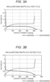
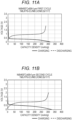
- the results of an initial charge-discharge curve and cycle characteristics of the prepared electrode are both very poor.
- initial charge-discharge efficiency is low, and cycle degradation is severe, which are not practical.
- cycle degradation NPL 1 states that it is considered that as the Bi active material expands at the time of Li insertion, and contracts at the time of Li desorption, the active material becomes finer, and as a result, an electron conduction path cannot be secured, and decrease in the capacity occurs.
- the present inventors have focused on Bi not having a property that the potential is greatly different among a plurality of types of compounds formed with lithium, and excellent in discharge flatness as described above, and have intensively studied a battery capable of improving cycle characteristics. As a result, the present inventors have found a new technical idea that the cycle characteristics of a battery are improved when BiNi having a specific crystal structure, specifically, in which the crystal structure thereof belongs to C2/m is used as an active material, and have completed the present disclosure.
- a battery of a first aspect of the present disclosure includes:
- the battery according to the first aspect includes the electrode containing, as an active material, the BiNi having the crystal structure in which the space group thereof belongs to C2/m. Therefore, the battery according to the first aspect has improved cycle characteristics.
- an intensity ratio I(2)/I(1) of an intensity I(2) to an intensity I(1) may be less than or equal to 0.28, where the intensity I(1) is a height intensity of a maximum peak present in a range of a diffraction angle 2 ⁇ of from 29° to 31°, inclusive, and the intensity I(2) is a height intensity of a maximum peak present in a range of a diffraction angle 2 ⁇ of from 41° to 43°, inclusive.
- the battery according to the second aspect has high initial efficiency and improved cycle characteristics.
- the active material layer may contain at least one selected from the group consisting of LiBi and Li 3 Bi.
- the battery according to the third aspect has a more enhanced capacity and improved cycle characteristics.
- the active material layer need not contain a solid electrolyte.
- a battery having a higher capacity per volume and improved cycle characteristics is obtained.
- the active material layer may contain the BiNi as a main component of an active material.
- the active material layer may contain substantially only the BiNi as an active material.
- the current collector may contain Ni.
- the battery according to the seventh aspect has a more enhanced capacity and improved cycle characteristics.
- the active material layer may be a heat-treated plating layer.
- a battery having a higher capacity per volume and improved cycle characteristics is obtained.
- the electrolyte solution may contain an aprotic solvent and a lithium salt dissolved in the aprotic solvent.
- the battery according to the ninth aspect can achieve a lithium ion battery having an enhanced capacity and improved cycle characteristics.
- the aprotic solvent may contain at least one selected from the group consisting of vinylene carbonate, 2-methyltetrahydrofuran, fluoroethylene carbonate, and ethylene carbonate.
- the battery according to the tenth aspect has a more enhanced capacity and improved cycle characteristics.
- the aprotic solvent may contain vinylene carbonate and chain carbonate.
- the battery according to the eleventh aspect has more improved cycle characteristics.
- the first electrode may be a negative electrode
- the second electrode may be a positive electrode
- the battery according to the twelfth aspect has a more enhanced capacity and improved cycle characteristics.
- Fig. 1 is a cross-sectional view schematically illustrating a configuration example of battery 1000 according to an exemplary embodiment of the present disclosure.
- Battery 1000 includes first electrode 101, second electrode 103, and electrolyte solution 102.
- First electrode 101 includes current collector 100 and active material layer 104.
- Active material layer 104 contains BiNi. This BiNi has a monoclinic crystal structure having a space group of C2/m.
- Battery 1000 further includes, for example, separator 107 and exterior 108.
- Separator 107 is disposed between first electrode 101 and second electrode 103.
- First electrode 101 and second electrode 103 face each other with separator 107 interposed therebetween.
- First electrode 101, second electrode 103, separator 107, and electrolyte solution 102 are housed in exterior 108.
- Electrolyte solution 102 is, for example, an electrolyte solution with which first electrode 101, second electrode 103, and separator 107 are impregnated.
- the internal space of exterior 108 may be filled with electrolyte solution 102.
- active material layer 104 contains, as an active material, the BiNi having the monoclinic crystal structure of which the space group belongs to C2/m.
- Use of this BiNi as an active material solves problems of pulverization in charging and discharging of a Bi active material formed using a Bi powder and side reactions with an electrolyte solution. Therefore, reduction of an electron conduction path in active material layer 104 due to repeated charging and discharging is suppressed. As a result, battery 1000 has improved cycle characteristics.
- Battery 1000 is, for example, a lithium secondary battery.
- the features of the present technique will be described as described below by exemplifying a case where metal ions absorbed and released in active material layer 104 of first electrode 101 and second electrode 103 during charging and discharging of battery 1000 are lithium ions.
- Active material layer 104 may contain BiNi as a main component.
- “active material layer 104 contains BiNi as a main component” is defined as "the content of BiNi in active material layer 104 is more than or equal to 50 mass%".
- the content of BiNi in active material layer 104 can be obtained, for example, by confirming that Bi and Ni are contained in active material layer 104 by elemental analysis by energy dispersive X-ray analysis (EDX), and calculating the proportions of contained compounds by performing Rietveld analysis on the X-ray diffraction result of active material layer 104.
- EDX energy dispersive X-ray analysis
- Active material layer 104 containing the BiNi as a main component may be formed of, for example, BiNi formed in a thin film shape (hereinafter, referred to as a "BiNi thin film").
- an intensity ratio I(2)/I(1) of an intensity I(2) to an intensity I(1) may be less than or equal to 0.28, where the intensity I(1) is a height intensity of a maximum peak present in a range of a diffraction angle 2 ⁇ of from 29° to 31°, inclusive, and the intensity I(2) is a height intensity of a maximum peak present in a range of a diffraction angle 2 ⁇ of from 41° to 43°, inclusive.
- the maximum peak present in a range of a diffraction angle 2 ⁇ of from 29° to 31° inclusive in the X-ray diffraction pattern corresponds to a peak derived from the (2,2,1) plane of BiNi as an intermetallic compound.
- the maximum peak present in a range of a diffraction angle 2 ⁇ of from 41° to 43° inclusive in the X-ray diffraction pattern corresponds to a peak derived from the (2,2,3) plane of BiNi as an intermetallic compound.
- the peak intensity ratio I(2)/I(1) of less than or equal to 0.28 means that the proportion of the (2,2,3) plane relative to the (2,2,1) plane in the BiNi having a monoclinic crystal structure belonging to a space group C2/m is low on the surface of active material layer 104. That is, the peak intensity ratio I(2)/I(1) of less than or equal to 0.28 means that the orientation of the (2,2,1) plane is stronger on the surface of active material layer 104. Active material layer 104 having such orientation in the crystal structure of the BiNi on the surface thereof can have high adhesion to current collector 100. Therefore, since active material layer 104 has such surface orientation, deterioration of the current collecting property hardly occurs even when active material layer 104 repeatedly expands and contracts due to charging and discharging. Accordingly, battery 1000 of the present disclosure can have more improved cycle characteristics and a higher capacity.
- the X-ray diffraction pattern of active material layer 104 can be obtained by X-ray diffraction measurement by a ⁇ -2 ⁇ method using Cu-K ⁇ rays having wavelengths of 1.5405 ⁇ and 1.5444 ⁇ , that is, wavelengths of 0.15405 nm and 0.15444 nm.
- the diffraction angle of the peak in the X-ray diffraction pattern is defined as an angle indicating the maximum intensity of a convex portion at which the value of an SN ratio (that is, the ratio of a signal S to background noise N) is more than or equal to 1.3 and the full width at half maximum is less than or equal to 10°.
- the full width at half maximum is a width represented by a difference between two diffraction angles, and a width at which the intensity of the X-ray diffraction peak is a half value of I MAX , assuming that the maximum intensity of the X-ray diffraction peak is I MAX .
- Active material layer 104 that contains the BiNi as a main component and is formed of the BiNi thin film satisfying the above surface orientation can be prepared by, for example, electroplating.
- a method for producing first electrode 101 by preparing active material layer 104 by electroplating is, for example, as follows.
- first electrode 101 for example, current collector 100 serves as a base material.
- a current collector containing Ni is prepared as current collector 100.
- the method for producing first electrode 101 includes, for example, preparing a Bi plating layer on the current collector containing Ni by an electroplating method, and heating the current collector and the Bi plating layer to diffuse Ni contained in the current collector into the Bi plating layer, thereby obtaining an electrode in which an active material layer containing BiNi is formed on the current collector.
- the heating temperature of the current collector and the Bi plating layer may be, for example, more than or equal to 250°C, and may be more than or equal to 350°C.
- the method for producing first electrode 101 will be described more specifically.
- a base material for electroplating is prepared.
- current collector 100 serves as a base material.
- a nickel foil is prepared as current collector 100.
- the nickel foil is preliminarily degreased with an organic solvent, and then one surface of the foil is masked.
- the foil is immersed in an acidic solvent to perform degreasing, thereby activating the surface of the nickel foil.
- the activated nickel foil is connected to a power source so that a current can be applied thereto.
- the nickel foil connected to the power source is immersed in a bismuth plating bath.
- the bismuth plating bath for example, an organic acid bath containing Bi 3+ ions and an organic acid is used.
- the unmasked part of the nickel foil surface is electroplated with Bi by applying a current to the nickel foil with the current density and the application time being controlled.
- the nickel foil is recovered from the plating bath, the masking is removed, and the nickel foil is washed with pure water and dried.
- a Bi plating layer is prepared on the nickel foil surface.
- the bismuth plating bath used for preparing the Bi plating layer is not particularly limited, and can be appropriately selected from known bismuth plating baths capable of depositing a Bi simple substance thin film.
- an organic sulfonic acid bath a gluconic acid and ethylenediaminetetraacetic acid (EDTA) bath, or a citric acid and EDTA bath
- EDTA ethylenediaminetetraacetic acid
- a citric acid and EDTA bath can be used as the organic acid bath.
- a sulfuric acid bath may be used as the bismuth plating bath.
- An additive may be added to the bismuth plating bath.
- the target thickness of the Bi plating layer prepared by electroplating Bi is shown in Table 1.
- the nickel foil and the Bi plating layer prepared on the nickel foil are heated.
- Ni is diffused in solid phase from the nickel foil to the Bi plating layer, and an active material layer formed of a BiNi thin film can be prepared.
- a sample in which Bi is electroplated on the nickel foil is subjected to, for example, the heat treatment at a temperature of more than or equal to 250°C for more than or equal to 30 minutes and less than 100 hours in a non-oxidizing atmosphere, whereby Ni is diffused in solid phase from the nickel foil to the Bi plating layer, and an active material layer formed of a BiNi thin film can be prepared.
- the heat treatment was performed at a temperature of 400°C for 60 hours in an argon atmosphere to prepare an active material layer formed of a BiNi thin film.
- the structure of the surface of the prepared active material layer formed of the BiNi thin film was also analyzed by the surface X-ray diffraction measurement.
- Fig. 2 is a graph showing an example of an X-ray diffraction pattern of the active material layer formed of the BiNi thin film prepared on the nickel foil.
- the X-ray diffraction pattern was measured by the ⁇ -2 ⁇ method using Cu-Ka rays having wavelengths of 1.5405 ⁇ and 1.5444 ⁇ as X-rays from the surface of the active material layer, that is, the thickness direction of active material layer 104, by use of an X-ray diffractometer (MiNi Flex, manufactured by Rigaku Corporation). From the X-ray diffraction pattern shown in Fig.
- the X-ray diffraction pattern shown in Fig. 2 is an X-ray diffraction pattern obtained by the surface X-ray diffraction measurement of an active material layer in a first electrode prepared in Example 1, which will be described later.
- a peak intensity ratio I(2)/I(1) of an intensity I(2) to an intensity I(1) was less than or equal to 0.28, where the intensity I(1) was a height intensity of a maximum peak present in a range of a diffraction angle 2 ⁇ of from 29° to 31°, inclusive, and the intensity I(2) was a height intensity of a maximum peak present in a range of a diffraction angle 2 ⁇ of from 41° to 43°, inclusive.
- the (2,2,1) plane of the BiNi having the monoclinic crystal structure in which the space group thereof belongs to C2/m can be oriented to be a surface by preparing the Bi plating layer on the current collector containing Ni, and performing the heat treatment on the obtained Bi plating layer on the current collector containing Ni.
- An electrode in which the BiNi thin film having such orientation is provided as the active material layer can further improve the cycle characteristics of the battery.
- first electrode 101 is a negative electrode and second electrode 103 is a positive electrode.
- first electrode 101 includes current collector 100 and active material layer 104.
- the configuration of active material layer 104 is as described above.
- First electrode 101 functions as a negative electrode. Therefore, active material layer 104 contains a negative electrode active material having a property of absorbing and releasing lithium ions.
- Active material layer 104 contains the BiNi having the crystal structure in which the space group thereof belongs to C2/m, and this BiNi functions as the negative electrode active material.
- Active material layer 104 contains the BiNi as the active material.
- Bi is a metal element that is alloyed with lithium.
- Ni is not alloyed with lithium, it is presumed that the load on the crystal structure of the negative electrode active material is reduced at the time of desorption and insertion of lithium atoms associated with charging and discharging, and a decrease in the capacity retention rate of the battery is suppressed in an alloy containing Ni.
- BiNi functions as the negative electrode active material
- Bi forms an alloy with lithium during charging, to thereby absorb lithium therein. That is, in active material layer 104, a lithium bismuth alloy is produced during charging of battery 1000.
- the lithium bismuth alloy to be produced contains, for example, at least one selected from the group consisting of LiBi and Li 3 Bi.
- active material layer 104 contains, for example, at least one selected from the group consisting of LiBi and Li 3 Bi. During discharging of battery 1000, lithium is released from the lithium bismuth alloy, and the lithium bismuth alloy returns to BiNi.
- the BiNi as the negative electrode active material reacts during charging and discharging of battery 1000, for example, as follows.
- the following reaction is an example of a case where the lithium bismuth alloy produced during charging is Li 3 Bi.
- Active material layer 104 may contain substantially only the BiNi as the active material. In this case, battery 1000 can have an enhanced capacity and improved cycle characteristics. Note that “active material layer 104 contains substantially only the BiNi as the active material” means that, for example, in active materials contained in active material layer 104, an active material other than the BiNi is less than or equal to 1 mass%. Active material layer 104 may contain only the BiNi as the active material.
- Active material layer 104 need not contain a solid electrolyte.
- Active material layer 104 may be disposed in direct contact with the surface of current collector 100.
- Active material layer 104 may have a thin film shape.
- Active material layer 104 may be a heat-treated plating layer. Active material layer 104 may be a heat-treated plating layer provided in direct contact with the surface of current collector 100. That is, active material layer 104 may be a layer formed by performing the heat treatment on the Bi plating layer formed on current collector 100 containing Ni as described above.
- active material layer 104 When active material layer 104 is a heat-treated plating layer provided in direct contact with the surface of current collector 100, active material layer 104 is firmly in close contact with current collector 100. This makes it possible to further suppress deterioration of the current collecting characteristics of first electrode 101, the deterioration occurring when active material layer 104 repeatedly expands and contracts. Therefore, the cycle characteristics of battery 1000 are further improved. Furthermore, when active material layer 104 is a heat-treated plating layer, Bi to be alloyed with lithium is contained in active material layer 104 at a high density, so that a higher capacity can be achieved.
- Active material layer 104 may contain a material other than the BiNi.
- Active material layer 104 may further contain a conductive material.
- Examples of the conductive material include carbon materials, metals, inorganic compounds, and conductive polymers.
- Examples of the carbon material include graphite, acetylene black, carbon black, Ketjen black, carbon whisker, needle coke, and carbon fiber.
- Examples of the graphite include natural graphite and artificial graphite. Examples of the natural graphite include massive graphite and flake graphite.
- Examples of the metal include copper, nickel, aluminum, silver, and gold.
- Examples of the inorganic compound include tungsten carbide, titanium carbide, tantalum carbide, molybdenum carbide, titanium boride, and titanium nitride. These materials may be used singly or in combination of two or more.
- Active material layer 104 may further contain a binder.
- binder examples include fluorine-containing resins, thermoplastic resins, ethylene propylene diene monomer (EPDM) rubber, sulfonated EPDM rubber, and natural butyl rubber (NBR).
- fluorine-containing resin examples include polytetrafluoroethylene (PTFE), polyvinylidene fluoride (PVdF), and fluororubber.
- thermoplastic resin examples include polypropylene and polyethylene. These materials may be used singly or in combination of two or more.
- the thickness of active material layer 104 is not particularly limited, and may be, for example, from 1 ⁇ m to 100 ⁇ m, inclusive.
- the material of current collector 100 is, for example, a single metal or alloy. More specifically, the material of current collector 100 may be a single metal or alloy containing at least one selected from the group consisting of copper, chromium, nickel, titanium, platinum, gold, aluminum, tungsten, iron, and molybdenum. Current collector 100 may be stainless steel.
- Current collector 100 may contain nickel (Ni).
- Current collector 100 may have a plate shape or a foil shape.
- the negative electrode current collector may be a metal foil or a metal foil containing nickel.
- the metal foil containing nickel include a nickel foil and a nickel alloy foil.
- the content of nickel in the metal foil may be more than or equal to 50 mass%, or more than or equal to 80 mass%.
- the metal foil may be a nickel foil containing substantially only nickel as a metal.
- Current collector 100 may be obtained by forming a Ni layer such as a Ni plating layer on the surface of a metal foil formed of a metal or an alloy other than nickel.
- Current collector 100 may be a layered film.
- Electrolyte solution 102 contains, for example, an aprotic solvent and a lithium salt dissolved in the aprotic solvent.
- the aprotic solvent is not particularly limited.
- the aprotic solvent include cyclic carbonate ester solvents, chain carbonate ester (chain carbonate) solvents, cyclic ether solvents, chain ether solvents, cyclic ester solvents, chain ester solvents, and fluorine solvents.
- the cyclic carbonate ester solvent include vinylene carbonate, fluoroethylene carbonate, ethylene carbonate, propylene carbonate, and butylene carbonate.
- Examples of the chain carbonate ester solvent include dimethyl carbonate, methyl ethyl carbonate, and diethyl carbonate.
- Examples of the cyclic ether solvent include tetrahydrofuran, 2-methyltetrahydrofuran, 1,4-dioxane, and 1,3-dioxolane.
- Examples of the chain ether solvent include 1,2-dimethoxyethane and 1,2-diethoxyethane.
- Examples of the cyclic ester solvent include ⁇ -butyrolactone.
- Examples of the chain ester solvent include methyl acetate.
- Examples of the fluorine solvent include methyl fluoropropionate, fluorobenzene, fluoroethyl methyl carbonate, and fluorodimethylene carbonate.
- Electrolyte solution 102 may contain one type of solvent selected from these solvents, or may contain a mixture of two or more types of non-aqueous solvents selected from these solvents.
- Electrolyte solution 102 may contain at least one selected from the group consisting of vinylene carbonate, 2-methyltetrahydrofuran, fluoroethylene carbonate, and ethylene carbonate as the aprotic solvent. Since electrolyte solution 102 contains these solvents, battery 1000 has more improved cycle characteristics.
- Electrolyte solution 102 may contain vinylene carbonate and chain carbonate as the aprotic solvent. Since electrolyte solution 102 contains a solvent mixture containing vinylene carbonate and chain carbonate, battery 1000 has more improved cycle characteristics.
- the chain carbonate is not particularly limited.
- Examples of the chain carbonate include dimethyl carbonate, methyl ethyl carbonate, and diethyl carbonate.
- the proportions of the vinylene carbonate and the chain carbonate are not particularly limited.
- the ratio of the chain carbonate to the vinylene carbonate may be more than 0 and less than or equal to 99 in terms of volume ratio.
- the aprotic solvent contained in electrolyte solution 102 may contain only the vinylene carbonate and the chain carbonate. That is, the proportion of the total mass of the vinylene carbonate and the chain carbonate in the total mass of the non-aqueous solvent may be, for example, 100 mass%.
- electrolyte solution 102 may further contain other aprotic solvents than the vinylene carbonate and the chain carbonate.
- the proportion of the total mass of the other aprotic solvents is, for example, less than or equal to 10 mass%.
- the other aprotic solvents include cyclic carbonate solvents, cyclic ether solvents, chain ether solvents, cyclic ester solvents, chain ester solvents, and fluorine solvents.
- the cyclic carbonate solvent include fluoroethylene carbonate, ethylene carbonate, propylene carbonate, and butylene carbonate.
- Examples of the cyclic ether solvent include tetrahydrofuran, 2-methyltetrahydrofuran, 1,4-dioxane, and 1,3-dioxolane.
- Examples of the chain ether solvent include 1,2-dimethoxyethane and 1,2-diethoxyethane.
- Examples of the cyclic ester solvent include ⁇ -butyrolactone.
- Examples of the chain ester solvent include methyl acetate.
- Examples of the fluorine solvent include methyl fluoropropionate, fluorobenzene, fluoroethyl methyl carbonate, and fluorodimethylene carbonate.
- lithium salt examples include LiPF 6 , LiBF 4 , LiSbF 6 , LiAsF 6 , LiSO 3 CF 3 , LiN(SO 2 CF 3 ) 2 , LiN(SO 2 C 2 F 5 ) 2 , LiN(SO 2 CF 3 )(SO 2 C 4 F 9 ), and LiC(SO 2 CF 3 ) 3 .
- One type of lithium salt selected from these may be used singly. Alternatively, a mixture of two or more types of lithium salts selected from these may be used.
- Second electrode 103 functions as a positive electrode.
- Second electrode 103 contains a material capable of absorbing and releasing metal ions such as lithium ions.
- the material is, for example, a positive electrode active material.
- Second electrode 103 may include current collector 105 and active material layer 106.
- Active material layer 106 contains a positive electrode active material.
- Active material layer 106 may be disposed on the surface of current collector 105 in direct contact with current collector 105.
- a lithium-containing transition metal oxide for example, a lithium-containing transition metal oxide, a transition metal fluoride, a polyanion material, a fluorinated polyanion material, a transition metal sulfide, a transition metal oxysulfide, a transition metal oxynitride, or the like can be used.
- the lithium-containing transition metal oxide include LiNi i-x-y Co x Al y O 2 ((x + y) ⁇ 1), LiNi 1-x-y Co x Mn y O 2 ((x + y) ⁇ 1), and LiCoO 2 .
- the positive electrode active material may contain, for example, Li(Ni,Co,Mn)O 2 .
- Examples of the material of current collector 105 include metal materials.
- Examples of the metal material include copper, stainless steel, iron, and aluminum.
- Second electrode 103 may contain a solid electrolyte.
- a solid electrolyte a known solid electrolyte used for a lithium secondary battery can be used.
- a halide solid electrolyte, a sulfide solid electrolyte, an oxide solid electrolyte, a polymer solid electrolyte, or a complex hydride solid electrolyte may be used.
- the halide solid electrolyte means a solid electrolyte containing a halogen element.
- the halide solid electrolyte may contain not only a halogen element but also oxygen.
- the halide solid electrolyte contains no sulfur (S).
- the halide solid electrolyte may be, for example, a material represented by the following compositional formula (1).
- the "metalloid element” is B, Si, Ge, As, Sb, and Te.
- the "metal element” refers to all elements included in Groups 1 to 12 of the periodic table except hydrogen, and all elements included in Groups 13 to 16 except B, Si, Ge, As, Sb, Te, C, N, P, O, S, and Se. That is, the metal element is an element group that can be a cation when the element is combined with a halogen compound to form an inorganic compound.
- M may contain Y, and X may contain Cl and Br.
- the sulfide solid electrolyte means a solid electrolyte containing sulfur (S).
- the sulfide solid electrolyte may contain not only sulfur but also a halogen element.
- Li 2 S-P 2 S 5 Li 2 S-SiS 2 , Li 2 S-B 2 S 3 , Li 2 S-GeS 2 , Li 3.25 Ge 0.25 P 0.75 S 4 , or Li 10 GeP 2 S 12 can be used.
- oxide solid electrolyte for example, a NASICON-type solid electrolyte typified by LiTi 2 (PO 4 ) 3 and an element-substituted compound thereof, a (LaLi)TiO 3 -based perovskite-type solid electrolyte, a LISICON-type solid electrolyte typified by Li 14 ZnGe 4 O 16 , Li 4 SiO 4 , LiGeO 4 and an element-substituted compound thereof, a garnet-type solid electrolyte typified by Li 7 La 3 Zr 2 O 12 and an element-substituted compound thereof, Li 3 PO 4 and an N-substituted compound thereof, and glass or glass ceramics in which Li 2 SO 4 , Li 2 CO 3 , or the like is added to a Li-B-O compound as a base such as LiBO 2 and Li 3 BO 3 can be used.
- a compound of a polymer compound and a lithium salt can be used.
- the polymer compound may have an ethylene oxide structure.
- the polymer compound having an ethylene oxide structure can contain a large amount of lithium salt. Therefore, ionic conductivity can be increased.
- As the lithium salt LiPF 6 , LiBF 4 , LiSbF 6 , LiAsF 6 , LiSO 3 CF 3 , LiN(SO 2 CF 3 ) 2 , LiN(SO 2 C 2 F 5 ) 2 , LiN(SO 2 CF 3 )(SO 2 C 4 F 9 ), LiC(SO 2 CF 3 ) 3 , and the like can be used.
- One type of lithium salt selected from the exemplified lithium salts can be used singly. Alternatively, a mixture of two or more types of lithium salts selected from the exemplified lithium salts can be used.
- the complex hydride solid electrolyte for example, LiBH 4 -LiI, LiBH 4 -P 2 S 5 , and the like can be used.
- the positive electrode active material may have a median diameter of from 0.1 ⁇ m to 100 ⁇ m, inclusive.
- the positive electrode active material has a median diameter of more than or equal to 0.1 ⁇ m, the positive electrode active material and the solid electrolyte can form a good dispersion state. This improves the charge-discharge characteristics of the battery.
- the positive electrode active material has a median diameter of less than or equal to 100 ⁇ m, a lithium diffusion rate is improved. This allows the battery to operate at high output power.
- the positive electrode active material may have a median diameter larger than that of the solid electrolyte. As a result, the positive electrode active material and the solid electrolyte can form a good dispersion state.
- the ratio of the volume of the positive electrode active material to the total volume of the positive electrode active material and the solid electrolyte may be from 0.30 to 0.95, inclusive.
- a coating layer may be formed on the surface of the positive electrode active material. This makes it possible to suppress an increase in reaction overvoltage of the battery.
- a coating material contained in the coating layer include sulfide solid electrolytes, oxide solid electrolytes, and halide solid electrolytes.
- the thickness of second electrode 103 may be from 10 ⁇ m to 500 ⁇ m, inclusive. When the thickness of second electrode 103 is more than or equal to 10 ⁇ m, a sufficient energy density of the battery can be ensured. When the thickness of second electrode 103 is less than or equal to 500 ⁇ m, the battery can operate at high output power.
- Second electrode 103 may contain a conductive material for the purpose of enhancing electron conductivity.
- Second electrode 103 may contain a binder.
- the same materials as the materials that can be used for active material layer 104 may be used.
- Second electrode 103 may contain a non-aqueous electrolyte solution, a gel electrolyte, or an ionic liquid for the purpose of facilitating transfer of lithium ions and improving the output characteristics of the battery.
- the non-aqueous electrolyte solution contains a non-aqueous solvent, and a lithium salt dissolved in the non-aqueous solvent.
- the non-aqueous solvent include cyclic carbonate ester solvents, chain carbonate ester solvents, cyclic ether solvents, chain ether solvents, cyclic ester solvents, chain ester solvents, and fluorine solvents.
- the cyclic carbonate ester solvent include ethylene carbonate, propylene carbonate, and butylene carbonate.
- Examples of the chain carbonate ester solvent include dimethyl carbonate, ethyl methyl carbonate, and diethyl carbonate.
- Examples of the cyclic ether solvent include tetrahydrofuran, 1,4-dioxane, and 1,3-dioxolane.
- Examples of the chain ether solvent include 1,2-dimethoxyethane and 1,2-diethoxyethane.
- Examples of the cyclic ester solvent include ⁇ -butyrolactone.
- Examples of the chain ester solvent include methyl acetate.
- Examples of the fluorine solvent include fluoroethylene carbonate, methyl fluoropropionate, fluorobenzene, fluoroethyl methyl carbonate, and fluorodimethylene carbonate.
- One type of non-aqueous solvent selected from these solvents may be used singly. Alternatively, a mixture of two or more types of non-aqueous solvents selected from these solvents may be used.
- lithium salt examples include LiPF 6 , LiBF 4 , LiSbF 6 , LiAsF 6 , LiSO 3 CF 3 , LiN(SO 2 CF 3 ) 2 , LiN(SO 2 C 2 F 5 ) 2 , LiN(SO 2 CF 3 )(SO 2 C 4 F 9 ), and LiC(SO 2 CF 3 ) 3 .
- One type of lithium salt selected from these may be used singly. Alternatively, a mixture of two or more types of lithium salts selected from these may be used.
- the concentration of the lithium salt ranges, for example, from 0.5 mol/liter to 2 mol/liter, inclusive.
- a polymer material impregnated with a non-aqueous electrolyte solution can be used.
- the polymer material include polyethylene oxide, polyacrylonitrile, polyvinylidene fluoride, polymethyl methacrylate, and polymers having an ethylene oxide bond.
- Examples of the cation contained in the ionic liquid include:
- Examples of the anion contained in the ionic liquid include PF 6 - , BF 4 - , SbF 6 - , AsF 6 - , SO 3 CF 3 - , N(SO 2 CF 3 ) 2 - , N(SO 2 C 2 F 5 ) 2 - , N(SO 2 CF 3 )(SO 2 C 4 F 9 ) - , and C(SO 2 CF 3 ) 3 - .
- the ionic liquid may contain a lithium salt.
- Separator 107 has lithium ion conductivity.
- the material of separator 107 is not particularly limited, as long as lithium ions are allowed to pass through the material.
- the material of separator 107 may be at least one selected from the group consisting of solid electrolytes, gel electrolytes, ion exchange resin membranes such as a lithium cation exchange resin, semipermeable membranes, and porous membranes. When separator 107 is made of these materials, the safety of battery 1000 can be sufficiently ensured.
- the solid electrolyte include sulfide solid electrolytes such as Li 2 S-P 2 S 5 , and oxide solid electrolytes such as Li 7 La 3 Zr 2 O 12 (LLZ).
- Examples of the gel electrolyte include gel electrolytes containing a fluororesin such as PVdF.
- Examples of the ion exchange resin membrane include cation exchange membranes and anion exchange membranes.
- Examples of the porous membrane include a porous membrane made of a polyolefin resin and a porous membrane made of glass paper obtained by weaving glass fibers into a nonwoven fabric.
- Exterior 108 is made of, for example, a material obtained by laminating a metal foil such as an aluminum foil with a resin film such as a polyethylene terephthalate (PET) film. Exterior 108 may be a container made of resin or metal.
- a metal foil such as an aluminum foil
- a resin film such as a polyethylene terephthalate (PET) film.
- Exterior 108 may be a container made of resin or metal.
- first electrode 101 is a negative electrode and second electrode 103 is a positive electrode has been described.
- first electrode 101 may be a positive electrode and second electrode 103 may be a negative electrode.
- active material layer 104 is a positive electrode active material layer. That is, Bi contained in active material layer 104 functions as a positive electrode active material.
- second electrode 103 as a negative electrode is formed of, for example, lithium metal.
- Battery 1000 has a basic configuration including first electrode 101, electrolyte solution 102, and second electrode 103, and is sealed in a sealed container to prevent air and moisture from entering therein.
- Examples of the shape of battery 1000 include a coin shape, a cylindrical shape, a square shape, a sheet shape, a button shape, a flat shape, and a laminated shape.
- a nickel foil (10 cm ⁇ 10 cm, thickness: 10 ⁇ m) was preliminarily degreased with an organic solvent, and then one surface of the foil was masked. The foil was immersed in an acidic solvent to perform degreasing, thereby activating the surface of the nickel foil.
- a plating bath was prepared by adding bismuth methanesulfonate as a soluble bismuth salt to 1.0 mol/L methanesulfonic acid so that the concentration of Bi 3+ ions was 0.18 mol/L.
- the activated nickel foil was connected to a power source so that a current can be applied thereto, and then immersed in the plating bath.
- the unmasked part of the nickel foil surface was electroplated with Bi so as to have a thickness of about 1 ⁇ m by controlling the current density to 2 A/dm 2 .
- the nickel foil was recovered from the acidic bath, the masking was removed, and the nickel foil was washed with pure water and dried.
- the nickel foil electroplated with Bi was heat-treated at 400°C for 60 hours in an electric furnace in an argon atmosphere. After the heat treatment, the Bi plating layer on the nickel foil was subjected to surface X-ray diffraction measurement. An X-ray diffraction pattern obtained by this measurement is as shown in Fig. 2 .
- the first electrode was used as a working electrode.
- a counter electrode Li metal having a thickness of 0.34 mm was used.
- the working electrode corresponds to a negative electrode of a secondary battery.
- the Li metal was doubly coated with a microporous separator (Celgard 3401, Asahi Kasei Corporation).
- a microporous separator (Celgard 3401, Asahi Kasei Corporation).
- an electrolyte solution a solution in which LiPF 6 was dissolved in each solvent shown in Table 2 at a concentration of 1.0 mol/L was prepared. Batteries as test cells of Examples 1-1 to 1-9 were assembled using such a working electrode, a counter electrode, and an electrolyte solution.
- the test cells thus prepared are monopolar test cells including a working electrode and a counter electrode, and are used to test the performance of one of electrodes in a secondary battery. Specifically, an electrode to be tested is used as the working electrode, and an appropriate active material in a sufficient amount to cover the reaction of the working electrode is used for the counter electrode. Since these test cells were used to test the performance of the first electrode as a negative electrode, a large excess of Li metal was used as the counter electrode as is usually used.
- the negative electrode whose performance has been tested using such test cells can be used as a secondary battery, for example, by being combined with a positive electrode containing a positive electrode active material as described in the above exemplary embodiment, for example, a transition metal oxide containing Li.
- a charge-discharge test was performed on the test cells. At a constant current value of 0.6 mA (0.15 mA/cm 2 ), the test cells were charged up to 0 V, and discharged up to 2 V. This was defined as one cycle. The discharge cycle test was performed at 25°C.
- Fig. 3A is a graph showing the result of an initial charge-discharge test of the test cell according to Example 1-1.
- Fig. 3B is a graph showing the result of a second charge-discharge test of the test cell according to Example 1-1.
- Fig. 4A is a graph showing the result of an initial charge-discharge test of the test cell according to Example 1-2.
- Fig. 4B is a graph showing the result of a second charge-discharge test of the test cell according to Example 1-2.
- Fig. 5A is a graph showing the result of an initial charge-discharge test of the test cell according to Example 1-3.
- Fig. 5B is a graph showing the result of a second charge-discharge test of the test cell according to Example 1-3.
- Fig. 6A is a graph showing the result of an initial charge-discharge test of the test cell according to Example 1-4.
- Fig. 6B is a graph showing the result of a second charge-discharge test of the test cell according to Example 1-4.
- Fig. 7A is a graph showing the result of an initial charge-discharge test of the test cell according to Example 1-5.
- Fig. 7B is a graph showing the result of a second charge-discharge test of the test cell according to Example 1-5.
- Fig. 8A is a graph showing the result of an initial charge-discharge test of the test cell according to Example 1-6.
- Fig. 8B is a graph showing the result of a second charge-discharge test of the test cell according to Example 1-6.
- Fig. 9A is a graph showing the result of an initial charge-discharge test of the test cell according to Example 1-7.
- Fig. 9B is a graph showing the result of a second charge-discharge test of the test cell according to Example 1-7.
- Fig. 10A is a graph showing the result of an initial charge-discharge test of the test cell according to Example 1-8.
- Fig. 10B is a graph showing the result of a second charge-discharge test of the test cell according to Example 1-8.
- Fig. 11A is a graph showing the result of an initial charge-discharge test of the test cell according to Example 1-9.
- Fig. 11B is a graph showing the result of a second charge-discharge test of the test cell according to Example 1-9.
- Fig. 12A is a graph showing the result of an initial charge-discharge test of the test cell according to Example 1-10.
- Fig. 12B is a graph showing the result of a second charge-discharge test of the test cell according to Example 1-10.
- Fig. 13 is a graph showing the result of an initial charge-discharge test of the test cell according to Example 1-11.
- Fig. 14 is a graph showing the result of an initial charge-discharge test of the test cell according to Example 1-12.
- Fig. 15 is a graph showing a relationship between the number of cycles and the discharge capacity density of the test cells according to Examples 1-1 to 1-8.
- Fig. 16 is a graph showing a relationship between the number of cycles and the discharge capacity density of the test cells according to Examples 1-1 to 1-4.
- Fig. 17 is a graph showing a relationship between the number of cycles and the discharge capacity density of the test cells according to Examples 1-1 and 1-9.
- Fig. 18 is a graph showing a relationship between the number of cycles and the discharge capacity density of the test cell according to Example 1-10.
- Fig. 19 is a graph showing a relationship between the number of cycles and the discharge capacity density of the test cells according to Examples 1-11 and 1-12.
- Fig. 25 is a graph showing an example of X-ray diffraction patterns of the active material layer before charging, after charging, and after discharging in the test cell according to Example 1-1.
- BiNi having a monoclinic crystal structure belonging to a space group C2/m and Ni having a cubic crystal structure belonging to a space group Fm-3m can be identified, and compounds derived from the active material and the current collector can be identified.
- Li 3 Bi having a cubic crystal structure belonging to a space group Fm-3m and Ni having a cubic crystal structure belonging to a space group Fm-3m can be identified. That is, it was confirmed that Li 3 Bi was generated after charging, and the charge reaction: BiNi + 3Li + + 3e' ⁇ Li 3 Bi + Ni progressed. Furthermore, after charging and discharging, BiNi having a monoclinic crystal structure belonging to a space group C2/m and Ni having a cubic crystal structure belonging to a space group Fm-3m can be identified. It was confirmed that the charge-discharge reactions were reversible from the viewpoint of the configuration of the compounds before charging by the discharge reaction: Li 3 Bi + Ni ⁇ BiNi + 3Li + + 3e - .
- Fig. 26 is a photograph of the first electrode in Example 1-1 after 500 cycles of charging and discharging. From the photograph of Fig. 26 , it was confirmed that the first electrode in Example 1-1 did not collapse even after 500 cycles of charging and discharging, and was in a very clean state.
- Example 2 a first electrode was prepared by the same method as in Example 1 except that the heat treatment conditions were changed from 400°C and 60 hours. In Example 2, after the heat treatment was performed at 250°C for 0.5 hours, the heat treatment was further performed at 350°C for 0.5 hours. In Example 2, after the heat treatment, the Bi plating layer on the nickel foil was also subjected to surface X-ray diffraction measurement similarly to Example 1.
- Fig. 20 is a graph showing an X-ray diffraction pattern of an active material layer formed of a BiNi thin film prepared on the nickel foil in Example 2. From this X-ray diffraction pattern, it was confirmed that BiNi having a monoclinic crystal structure belonging to a space group C2/m was generated.
- Example 2 a first electrode including a current collector formed of the nickel foil and an active material layer which was formed of the BiNi having the crystal structure belonging to the space group C2/m, and which was disposed in direct contact with the surface of the current collector, was obtained similarly to Example 1.
- a peak intensity ratio I(2)/I(1) of the active material layer calculated from this X-ray diffraction pattern was less than or equal to 0.28.
- Example 2 The first electrode of Example 2 was used as a working electrode, and a solution in which LiPF 6 was dissolved in VC at a concentration of 1.0 mol/L was used as an electrolyte solution. Except for these points, a test cell was prepared in the same manner as in Example 1.
- FIG. 21A is a graph showing the result of an initial charge-discharge test of the test cell according to Example 2.
- Fig. 21B is a graph showing the result of a second charge-discharge test of the test cell according to Example 2. From the results of the charge-discharge tests of the test cell according to Example 2, it was confirmed that the battery including the electrode containing the BiNi as an active material was excellent in discharge flatness. In the second charge-discharge, the same level of charge-discharge capacity as the initial charge-discharge capacity was obtained.
- Fig. 22 is a graph showing a relationship between the number of cycles and the discharge capacity density of the test cell according to Example 2 and a test cell according to Example 3.
- Example 3 a first electrode was prepared by the same method as in Example 1 except that the heat treatment conditions were changed from 400°C and 60 hours. In Example 3, the heat treatment was performed at 250°C for 0.5 hours. Also in Example 3, after the heat treatment, the Bi plating layer on the nickel foil was also subjected to surface X-ray diffraction measurement similarly to Example 1.
- Fig. 23 is a graph showing an X-ray diffraction pattern of an active material layer formed of a BiNi thin film prepared on the nickel foil in Example 3.
- Example 3 a first electrode including a current collector formed of the nickel foil and an active material layer which containing the BiNi and Bi 3 Ni, and which was disposed in direct contact with the surface of the current collector, was obtained.
- Example 3 The first electrode of Example 3 was used as a working electrode, and a solution in which LiPF 6 was dissolved in VC at a concentration of 1.0 mol/L was used as an electrolyte solution. Except for these points, a test cell was prepared in the same manner as in Example 1.
- Fig. 24A is a graph showing the result of an initial charge-discharge test of the test cell according to Example 3.
- Fig. 24B is a graph showing the result of a second charge-discharge test of the test cell according to Example 3. From the results of the charge-discharge tests of the test cell according to Example 3, it was confirmed that the battery including the electrode containing the BiNi as an active material was excellent in discharge flatness. In the second charge-discharge, the same level of charge-discharge capacity as the initial charge-discharge capacity was obtained.
- Fig. 22 is a graph showing a relationship between the number of cycles and the discharge capacity density of the test cell according to Example 2 and a test cell according to Example 3.
- Bi 2 O 3 Bismuth trioxide "BIO10PB", manufactured by Kojundo Chemical Lab. Co., Ltd.
- NiO Nickel monoxide
- DENKA BLACK manufactured by Denka Company Limited
- the molar ratio of Bi 2 O 3 , NiO, and carbon was 2 : 4 : 5 (Bi 2 O 3 : NiO : carbon).
- the obtained mixture was sintered in a nitrogen atmosphere using an electric furnace to prepare a BiNi powder. The sintering was performed at 800°C for 4 hours.
- Fig. 27 is a graph showing an X-ray diffraction pattern of the BiNi powder prepared from the powder material in Example 4.
- the X-ray diffraction pattern was measured after the sintered BiNi powder was crushed in a mortar. The measurement was performed by the ⁇ -2 ⁇ method using Cu-Ka rays having wavelengths of 1.5405 ⁇ and 1.5444 ⁇ as X-rays, by use of an X-ray diffractometer (MiNi Flex, manufactured by Rigaku Corporation). From the obtained X-ray diffraction pattern, it was confirmed that BiNi was generated and the BiNi had a monoclinic crystal structure belonging to a space group C2/m.
- BiNi powder and acetylene black (AB) ("DENKA BLACK", manufactured by Denka Company Limited) as a conductive agent were dispersed in an N-methyl-2-pyrrolidone (NMP) solution of PVdF to prepare a slurry.
- PVdF was used as a binder.
- the mass ratio of BiNi powder, AB, and PVdF was 8 : 1 : 1 (BiNi powder : AB : PVdF).
- NMP N-methyl-2-pyrrolidone
- the first electrode of Example 4 was used as a working electrode, and a solution in which LiPF 6 was dissolved in VC or a solvent mixture at a concentration of 1.0 mol/L was used as an electrolyte solution. Except for these points, a test cell was prepared in the same manner as in Example 1.
- the test cell in which VC was used as the solvent of the electrolyte solution was used as a test cell according to Example 4-1.
- As the solvent mixture a solvent obtained by mixing EC, MEC, and DMC at a volume ratio of 6 : 7 : 7 (EC : MEC : DMC) was used.
- the test cell in which this solvent mixture was used as the solvent of the electrolyte solution was used as a test cell according to Example 4-2.
- a charge-discharge test was performed on the test cells. At a constant current value of 0.6 mA (0.15 mA/cm 2 ), the test cells were charged up to 0 V, and discharged up to 2 V. This was defined as one cycle. The charge-discharge cycle test was performed at 25°C.
- Fig. 28A is a graph showing the result of an initial charge-discharge test of the test cell according to Example 4-1.
- Fig. 28B is a graph showing the result of a second charge-discharge test of the test cell according to Example 4-1.
- Fig. 29A is a graph showing the result of an initial charge-discharge test of the test cell according to Example 4-2.
- Fig. 29B is a graph showing the result of a second charge-discharge test of the test cell according to Example 4-2.
- Fig. 30 is a graph showing a relationship between the number of cycles up to 50 cycles and the discharge capacity density of the test cells according to Examples 4-1 and 4-2.
- Fig. 31 is a graph showing a relationship between the number of cycles up to 10 cycles and the discharge capacity density of the test cells according to Examples 4-1 and 4-2.
- a copper foil was preliminarily degreased with an organic solvent, and then one surface of the foil was masked. The foil was immersed in an acidic solvent to perform degreasing, thereby activating the surface of the copper foil.
- a plating bath was prepared by adding bismuth methanesulfonate as a soluble bismuth salt to 1.0 mol/L methanesulfonic acid so that the concentration of Bi 3+ ions was 0.18 mol/L.
- the activated copper foil was connected to a power source so that a current can be applied thereto, and then immersed in the plating bath.
- the unmasked part of the copper foil surface was electroplated with Bi so as to have a thickness of about 1 ⁇ m by controlling the current density to 2 A/dm 2 .
- the copper foil was recovered from the acidic bath, and the masking was removed. Then, the copper foil was washed with pure water, dried, and punched into a size of 2 cm ⁇ 2 cm to obtain a first electrode. That is, the first electrode of Reference Example 1 had a configuration in which an active material layer formed of a Bi plating layer was provided on a current collector made of a copper foil.
- the first electrode of Reference Example 1 was used as a working electrode, and a solution in which LiPF 6 was dissolved in VC at a concentration of 1.0 mol/L was used as an electrolyte solution. Except for these points, a test cell was prepared in the same manner as in Example 1.
- FIG. 32A is a graph showing the result of an initial charge-discharge test of the test cell according to Reference Example 1.
- Fig. 32B is a graph showing the result of a second charge-discharge test of the test cell according to Reference Example 1. From Figs. 32A and 32B , the battery according to Reference Example 1 in which the Bi plating layer was used for the active material layer was excellent in discharge flatness, and furthermore, the charge-discharge capacity was substantially maintained in the second charge-discharge.
- Fig. 33 is a graph showing a relationship between the number of cycles and the discharge capacity density of the test cell according to Reference Example 1.
- a Bi powder (purity 3N fine powder, particle diameter: about 1 ⁇ m to 2 ⁇ m, manufactured by Kojundo Chemical Laboratory Co., Ltd.) and AB ("DENKA BLACK", manufactured by Denka Company Limited) as a conductive agent were dispersed in an NMP solution of PVdF to prepare a slurry.
- PVdF was used as a binder.
- the mass ratio of Bi powder, AB, and PVdF was 8 : 1 : 1 (Bi powder : AB : PVdF).
- this slurry was applied onto a copper foil (10 cm ⁇ 10 cm), the NMP as a solvent was removed, and the copper foil was molded and punched into 2 cm ⁇ 2 cm to prepare a first electrode.
- a test cell was assembled in the same manner as in Example 1 except that the first electrode prepared in Comparative Example 1 was used.
- a charge-discharge test was performed on the test cells. At a constant current value of 0.6 mA (0.15 mA/cm 2 ), the test cells were charged up to 0 V, and discharged up to 2 V. This was defined as one cycle. The charge-discharge cycle test was performed at 25°C.
- Fig. 34A is a graph showing the result of an initial charge-discharge test of the test cell according to Comparative Example 1.
- Fig. 34B is a graph showing the result of a second charge-discharge test of the test cell according to Comparative Example 1. From Figs. 34A and 34B , the battery according to Comparative Example 1 in which the Bi powder was used for the active material layer had very poor initial charge-discharge characteristics, and the second charge-discharge capacity further decreased.
- Fig. 35 is a graph showing a relationship between the number of cycles up to 10 cycles and the discharge capacity density of the test cell according to Comparative Example 1. From the results shown in Fig. 35 , the battery according to Comparative Example 1 in which the Bi powder was used for the active material layer had very poor cycle characteristics.
- the battery including the first electrode containing the BiNi in Examples 1 to 4 had improved cycle characteristics as compared with the battery including the first electrode containing the Bi.
- the batteries of Examples 1 to 3 in which the active material layer containing the BiNi had high orientation such that I(2)/I(1) satisfied less than or equal to 0.28 had more excellent cycle characteristics.
- the cycle characteristics were further improved when the solvent of the electrolyte solution contained at least one selected from the group consisting of VC, 2MeTHF, FEC, and EC.
- the solvent of the electrolyte solution contained at least one selected from the group consisting of VC, 2MeTHF, FEC, and EC.
- the batteries according to Examples 1-10, 1-11, and 1-12 in which the electrolyte solution containing the solvent mixture of vinylene carbonate and chain carbonate was used had more excellent cycle characteristics than the batteries according to Examples 1-6 and 1-8 in which the electrolyte solution containing only one type of chain carbonate as a solvent was used.
- the battery of the present disclosure can be used as, for example, an all-solid lithium secondary battery.
Landscapes
- Chemical & Material Sciences (AREA)
- General Chemical & Material Sciences (AREA)
- Chemical Kinetics & Catalysis (AREA)
- Electrochemistry (AREA)
- Engineering & Computer Science (AREA)
- Manufacturing & Machinery (AREA)
- Inorganic Chemistry (AREA)
- Materials Engineering (AREA)
- Physics & Mathematics (AREA)
- Condensed Matter Physics & Semiconductors (AREA)
- General Physics & Mathematics (AREA)
- Battery Electrode And Active Subsutance (AREA)
- Secondary Cells (AREA)
Applications Claiming Priority (4)
| Application Number | Priority Date | Filing Date | Title |
|---|---|---|---|
| JP2021071462 | 2021-04-20 | ||
| JP2021090669 | 2021-05-28 | ||
| JP2021182584 | 2021-11-09 | ||
| PCT/JP2022/006552 WO2022224571A1 (ja) | 2021-04-20 | 2022-02-18 | 電池 |
Publications (1)
| Publication Number | Publication Date |
|---|---|
| EP4329007A1 true EP4329007A1 (de) | 2024-02-28 |
Family
ID=83722788
Family Applications (1)
| Application Number | Title | Priority Date | Filing Date |
|---|---|---|---|
| EP22791354.8A Pending EP4329007A1 (de) | 2021-04-20 | 2022-02-18 | Batterie |
Country Status (3)
| Country | Link |
|---|---|
| EP (1) | EP4329007A1 (de) |
| JP (1) | JPWO2022224571A1 (de) |
| WO (1) | WO2022224571A1 (de) |
Family Cites Families (6)
| Publication number | Priority date | Publication date | Assignee | Title |
|---|---|---|---|---|
| JPH10241670A (ja) * | 1997-02-25 | 1998-09-11 | Sanyo Electric Co Ltd | 非水電解質二次電池用電極及びその製造方法 |
| JP4395898B2 (ja) * | 1997-06-03 | 2010-01-13 | パナソニック株式会社 | 非水電解質二次電池用負極材料とそれら負極材料を用いた非水電解質二次電池 |
| CN1163993C (zh) * | 1999-01-04 | 2004-08-25 | 东洋钢钣株式会社 | 碱性蓄电池的芯体以及使用此芯体的电池 |
| AU7951200A (en) | 1999-10-22 | 2001-04-30 | Sanyo Electric Co., Ltd. | Electrode for lithium cell and lithium secondary cell |
| EP1313158A3 (de) | 2001-11-20 | 2004-09-08 | Canon Kabushiki Kaisha | Elektrodenmaterial für wiederaufladbare Lithium-Batterie, solches Material enthaltende Elektrode, wiederaufladbare Lithium-Batterie mit dieser Elektrode und Herstellungsverfahren dafür |
| JP7010099B2 (ja) * | 2018-03-20 | 2022-01-26 | 株式会社Gsユアサ | 負極活物質、負極及び非水電解質蓄電素子 |
-
2022
- 2022-02-18 JP JP2023516307A patent/JPWO2022224571A1/ja active Pending
- 2022-02-18 WO PCT/JP2022/006552 patent/WO2022224571A1/ja active Application Filing
- 2022-02-18 EP EP22791354.8A patent/EP4329007A1/de active Pending
Also Published As
| Publication number | Publication date |
|---|---|
| WO2022224571A1 (ja) | 2022-10-27 |
| JPWO2022224571A1 (de) | 2022-10-27 |
Similar Documents
| Publication | Publication Date | Title |
|---|---|---|
| KR102503085B1 (ko) | 리튬 고체 상태 전해질 계면 처리 | |
| CN109309210B (zh) | 正极活性物质和电池 | |
| KR101228115B1 (ko) | 양극, 그 제조방법 및 이를 채용한 리튬전지 | |
| US11923529B2 (en) | Positive electrode active material and battery including same | |
| Shen et al. | Multifunctional SnSe–C composite modified 3D scaffolds to regulate lithium nucleation and fast transport for dendrite-free lithium metal anodes | |
| EP2831942B1 (de) | Polysulfonbeschichtung für lithium-ionen-hochspannungszellen | |
| US20240030418A1 (en) | Battery and method for manufacturing electrode | |
| US20240030419A1 (en) | Battery and method for manufacturing electrode | |
| JP7142302B2 (ja) | 正極活物質およびそれを備えた電池 | |
| WO2020012739A1 (ja) | 正極活物質およびそれを備えた電池 | |
| EP4329007A1 (de) | Batterie | |
| EP4287307A1 (de) | Batterie | |
| EP4287318A1 (de) | Batterie | |
| JP7281772B2 (ja) | 正極活物質およびそれを備えた電池 | |
| WO2023017735A1 (ja) | 電池 | |
| WO2023145426A1 (ja) | 電池および電極の製造方法 | |
| WO2023017673A1 (ja) | 電池 | |
| WO2023017672A1 (ja) | 電池 | |
| US20190326599A1 (en) | Cathode active material containing boron and carbon, and magnesium secondary battery using the same | |
| WO2023074590A1 (ja) | 電池 | |
| WO2023017736A1 (ja) | 電池 | |
| CN117121231A (zh) | 电池 | |
| WO2023106126A1 (ja) | 電池 | |
| WO2022163039A1 (ja) | 電池 | |
| US20240030501A1 (en) | Electrochemical cells including anodes comprising a protective layer, and related methods |
Legal Events
| Date | Code | Title | Description |
|---|---|---|---|
| STAA | Information on the status of an ep patent application or granted ep patent |
Free format text: STATUS: THE INTERNATIONAL PUBLICATION HAS BEEN MADE |
|
| PUAI | Public reference made under article 153(3) epc to a published international application that has entered the european phase |
Free format text: ORIGINAL CODE: 0009012 |
|
| STAA | Information on the status of an ep patent application or granted ep patent |
Free format text: STATUS: REQUEST FOR EXAMINATION WAS MADE |
|
| 17P | Request for examination filed |
Effective date: 20231013 |
|
| AK | Designated contracting states |
Kind code of ref document: A1 Designated state(s): AL AT BE BG CH CY CZ DE DK EE ES FI FR GB GR HR HU IE IS IT LI LT LU LV MC MK MT NL NO PL PT RO RS SE SI SK SM TR |