EP4328386A2 - Schwimmende struktur und verfahren zur montage solch einer struktur - Google Patents
Schwimmende struktur und verfahren zur montage solch einer struktur Download PDFInfo
- Publication number
- EP4328386A2 EP4328386A2 EP23219703.8A EP23219703A EP4328386A2 EP 4328386 A2 EP4328386 A2 EP 4328386A2 EP 23219703 A EP23219703 A EP 23219703A EP 4328386 A2 EP4328386 A2 EP 4328386A2
- Authority
- EP
- European Patent Office
- Prior art keywords
- floating
- module
- floating module
- wall
- extension
- Prior art date
- Legal status (The legal status is an assumption and is not a legal conclusion. Google has not performed a legal analysis and makes no representation as to the accuracy of the status listed.)
- Pending
Links
Images


Classifications
-
- B—PERFORMING OPERATIONS; TRANSPORTING
- B63—SHIPS OR OTHER WATERBORNE VESSELS; RELATED EQUIPMENT
- B63B—SHIPS OR OTHER WATERBORNE VESSELS; EQUIPMENT FOR SHIPPING
- B63B5/00—Hulls characterised by their construction of non-metallic material
- B63B5/14—Hulls characterised by their construction of non-metallic material made predominantly of concrete, e.g. reinforced
- B63B5/18—Hulls characterised by their construction of non-metallic material made predominantly of concrete, e.g. reinforced built-up from elements
-
- B—PERFORMING OPERATIONS; TRANSPORTING
- B63—SHIPS OR OTHER WATERBORNE VESSELS; RELATED EQUIPMENT
- B63B—SHIPS OR OTHER WATERBORNE VESSELS; EQUIPMENT FOR SHIPPING
- B63B35/00—Vessels or similar floating structures specially adapted for specific purposes and not otherwise provided for
- B63B35/34—Pontoons
- B63B35/38—Rigidly-interconnected pontoons
-
- B—PERFORMING OPERATIONS; TRANSPORTING
- B63—SHIPS OR OTHER WATERBORNE VESSELS; RELATED EQUIPMENT
- B63B—SHIPS OR OTHER WATERBORNE VESSELS; EQUIPMENT FOR SHIPPING
- B63B35/00—Vessels or similar floating structures specially adapted for specific purposes and not otherwise provided for
- B63B35/44—Floating buildings, stores, drilling platforms, or workshops, e.g. carrying water-oil separating devices
-
- E—FIXED CONSTRUCTIONS
- E02—HYDRAULIC ENGINEERING; FOUNDATIONS; SOIL SHIFTING
- E02B—HYDRAULIC ENGINEERING
- E02B3/00—Engineering works in connection with control or use of streams, rivers, coasts, or other marine sites; Sealings or joints for engineering works in general
- E02B3/04—Structures or apparatus for, or methods of, protecting banks, coasts, or harbours
- E02B3/06—Moles; Piers; Quays; Quay walls; Groynes; Breakwaters ; Wave dissipating walls; Quay equipment
- E02B3/062—Constructions floating in operational condition, e.g. breakwaters or wave dissipating walls
- E02B3/064—Floating landing-stages
-
- B—PERFORMING OPERATIONS; TRANSPORTING
- B63—SHIPS OR OTHER WATERBORNE VESSELS; RELATED EQUIPMENT
- B63B—SHIPS OR OTHER WATERBORNE VESSELS; EQUIPMENT FOR SHIPPING
- B63B2231/00—Material used for some parts or elements, or for particular purposes
- B63B2231/02—Metallic materials
-
- B—PERFORMING OPERATIONS; TRANSPORTING
- B63—SHIPS OR OTHER WATERBORNE VESSELS; RELATED EQUIPMENT
- B63B—SHIPS OR OTHER WATERBORNE VESSELS; EQUIPMENT FOR SHIPPING
- B63B2231/00—Material used for some parts or elements, or for particular purposes
- B63B2231/60—Concretes
Definitions
- the field of the present invention is that of floating structures, such as artificial islands or pontoons.
- the invention also relates to a method of assembling floating modules forming such a floating structure.
- monolithic floating structures formed from a single structural element are known.
- These monolithic floating structures have in particular the disadvantage of having limited dimensions which do not make it possible to produce a floating structure adapted to the desired dimensions or even to require specific infrastructures during their manufacture or their transport from their manufacturing site to a production site. destination, considerably increasing their manufacturing cost.
- Such so-called modular floating structures are also known, comprising several distinct floating modules, in particular made of concrete, assembled together to form the modular floating structure. It is known to ensure cohesion between the different floating modules by providing a cavity in the thickness of a wall of each floating module at a junction between a first floating module and a second floating module. A hollow formed by a first cavity of a first known floating module and a second floating module is then filled with a material, such as concrete, in particular liquid which, once solidified, ensures cohesion between the first floating module and the second floating module of the known modular floating structure.
- a material such as concrete, in particular liquid which, once solidified, ensures cohesion between the first floating module and the second floating module of the known modular floating structure.
- the cavity being formed in the thickness of the wall, the thickness of concrete poured in the hollow is only equal to a fraction of the thickness of the wall.
- only said fraction of the thickness of the wall ensures the mechanical strength of the assembly between the first floating module and the second floating module, thus causing structural weakness, particularly in terms of static, dynamic, hydrodynamic fatigue and sealing resistance, at the level of the assembly between the first floating module and the second floating module known from the known modular floating structure.
- the aim of the present invention is to propose a floating structure making it possible to fully respond to the disadvantages stated above and also lead to other advantages.
- the present invention aims to achieve a modular floating structure comprising two floating modules assembled with each other and connected by a material cast in a hollow between the first floating module and the second floating module, the hollow having a thickness identical to the thickness of the walls of the floating modules of the floating structure in order to ensure total mechanical continuity between the first floating module and the second floating module, and to obtain a modular floating structure which behaves like a structure monolithic with the same mechanical resistance as the current section of a floating module.
- the invention achieves this, according to a first aspect, thanks to a floating module comprising a plurality of walls extending between a first longitudinal end and a second longitudinal end, the floating module comprising a first partition and a second partition connecting each wall of the plurality of walls by defining with these walls an internal volume of the floating module, characterized in that the floating module comprises at least one extension emerging from an external face of the wall, the extension extending longitudinally projecting from the first end longitudinal or of the second longitudinal end, the extension and the wall from which the extension comes being produced by continuity of material.
- the walls extend mainly in a longitudinal axis.
- the longitudinal axis is intended to be horizontal.
- the first longitudinal end and the second longitudinal end designate the longitudinal ends of a wall, and not the longitudinal ends of the floating module.
- the first partition and the second partition extend in a vertical and transverse plane perpendicular to the longitudinal axis.
- the walls and partitions define the internal volume, which ensures the flotation of the floating module.
- the internal volume is entirely enclosed or almost entirely enclosed, the floating module comprising in the latter case an opening, particularly of a technical nature, made in a wall or in a partition.
- the module floating is configured to avoid or reduce the penetration of water inside the internal volume.
- the internal volume of the floating module is intended to be occupied by a material having a density less than 1, that is to say a density less than the density of water.
- Said material can be, for example air or a foam such as polyurethane, polyethylene or polystyrene foam, so that the floating module has a general density less than 1, thus ensuring the flotation of the floating module on the water.
- Each wall comprises an internal face and an external face located opposite the wall relative to the internal face, the internal face of the wall being oriented in the direction of the internal volume.
- a thickness of the wall is measured between the internal face of the wall and the external face of the wall.
- the extension emerges from the external face of the wall, the extension also extending longitudinally projecting from a longitudinal end of the wall, the extension and the wall from which the extension comes being produced by continuity of matter.
- the extension and the wall from which the extension comes are made of the same material, and do not present any separation of material.
- This configuration according to the invention makes it possible to produce a modular floating structure comprising at least one floating module conforming to the first aspect of the invention, said floating structure having total mechanical continuity between the assembled floating modules and behaving like a monolithic structure with the same mechanical resistance as the current section of a floating module, unlike a known modular floating structure.
- the extension and the wall from which the extension of a first floating module according to the invention comes delimit a first cavity.
- the cavity comprises a dimension, called the first dimension, along a vertical axis perpendicular to a longitudinal and transverse plane formed by the internal face of the wall, the first dimension can then represent at least the entire thickness of the wall measured between the external face and the internal face of the wall, this first dimension can also be greater than the thickness of the wall measured perpendicularly between the external face and the internal face of the wall.
- the cavity makes it possible to position the material connecting the first floating module and the second floating module, the material can then occupy the entirety of the first dimension of the cavity.
- this configuration makes it possible to ensure total mechanical continuity between the first floating module and a second floating module, and to obtain a modular floating structure which behaves like a monolithic structure having the same mechanical resistance as the current section of a floating module, the cavity delimited by the wall and the extension having a first dimension which can represent at least the entire thickness of the wall.
- the invention also relates to a floating structure comprising at least one floating module conforming to the first aspect of the invention.
- This configuration makes it possible in particular to form a floating structure, such as a bridge, an oil platform, a port, a pier, a floating platform for renewable energy, a nuclear structure, an artificial island, or any other type of floating structure. More particularly, this configuration allows the construction of a so-called modular floating structure, that is to say formed of several distinct floating modules assembled together. Indeed, the construction of a floating structure large modular structure is simplified in comparison to the construction of a monolithic floating structure formed from a single large structural element.
- the construction of a monolithic floating structure requires, for example, specific infrastructure or even suitable means of transport in order to transport the monolithic floating structure from its place of manufacture to its place of destination, while in the case of 'a modular floating structure, the floating modules forming said modular floating structure are individually of a size smaller than the size of the modular floating structure.
- the floating modules can also be assembled, in order to form the modular floating structure, directly at the destination of the modular floating structure, removing the constraints of transporting the floating structure.
- the invention makes it possible to ensure total mechanical continuity between the first floating module and a second floating module, and to obtain a modular floating structure which behaves like a monolithic structure having the same mechanical resistance as the section current of a floating module, unlike a known modular floating structure due to the use of a floating module conforming to the first aspect of the invention.
- the invention also relates to a method of assembling a floating structure according to the second aspect of the invention, the assembly method comprising a step of aligning the first floating module relative to the second floating module , a step of removable coupling of the first floating module to the second floating module, a step of coupling the reinforcements, the prestressing sheaths and the prestressing cables, and a step of pouring concrete into the hollow.
- the step of aligning the first floating module with respect to the second floating module allows the first cavity and the second cavity to face each other.
- a longitudinal termination of the first floating module is placed opposite a longitudinal termination of the second floating module.
- the step of aligning the first floating module relative to the second floating module makes it possible to position the first floating module and the second floating module in the same longitudinal axis. The first floating module and the second floating module are then brought closer to each other to allow the removable coupling step.
- the removable coupling step involves a connecting frame in order to secure the position of the first floating module and the second floating module during the assembly process, in particular when the assembly process is carried out directly on a body of water , which can cause movements of the first floating module relative to the second floating module.
- the connection frame is located on the periphery of the floating modules, the connection frame being removably connected to both the first floating module and the second floating module.
- the connecting frame can be removed.
- the connecting frame is secured to the first floating module prior to the rimpedement between the first floating module and the second floating module.
- the connecting frame is secured to the first floating module then to the second floating module once the connection between the first floating module and the second floating module is made.
- the removable coupling step also allows the sealing device to ensure the sealing of the interface between the first floating module and the second floating module.
- characteristics, variants and different embodiments of the invention can be associated with each other, in various combinations, to the extent that they are not incompatible or exclusive of each other. It will be possible in particular to imagine variants of the invention comprising only a selection of characteristics described subsequently in isolation from the other characteristics described, if this selection of characteristics is sufficient to confer a technical advantage or to differentiate the invention from to the prior art.
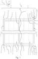
- FIG 1 illustrates a partial view, in section, of an exemplary embodiment of a floating module 1 conforming to the first aspect of the invention.
- the floating module 1 extends mainly along a longitudinal axis X and the vertical axis Z forming a plane D illustrated in figure 1 .
- the figure 1 illustrates a side sectional view of the floating module 1.
- the floating module 1 finally extends along the transverse axis Y perpendicular to the plane D.
- the floating module 1 comprises a plurality of walls, each wall 2 extending along the longitudinal axis partition 10 located respectively near the first longitudinal end 4 and the second longitudinal end 6.
- the plurality of walls, the first partition 8 and the second partition 10 define an internal volume 12, essentially closed, intended to be filled by a material having a density lower than the density of water in order to ensure the flotation of the floating module 1.
- a first portion 41 of the floating module 1 is submerged, that is to say located under a line of water 43, a second portion 42 located opposite the floating module relative to the first portion 41 along the vertical axis Z being for its part emerged, that is to say located above the line of water, in the air.
- the internal volume 12 is crossed by an intermediate wall 2' extending mainly in the longitudinal axis between the first partition 8 and the second partition 10, the internal volume 12 thus forming a first chamber 13 and a second chamber 15.
- the intermediate wall 2' makes it possible to reinforce the structure of the floating module 1.
- each wall 2 comprises an internal face 17 and an external face 16 located opposite the wall 2 with respect to the internal face, said internal face 17 being oriented towards the internal volume 12.
- a plurality of metal frames 22 extend longitudinally through the floating module, each metal frame 22 being intended to be connected to a metal frame 22 of a second floating module.
- the metal frames 22 make it possible to connect several floating modules together.
- the metal reinforcements 22 make it possible to ensure the resistance of the floating module 1 and the floating structure to mechanical forces, and more particularly to mechanical tensile forces, particularly in the case in which the walls 2, the first partition 8 and the second partition 10 of the floating module are made of a material, such as concrete, highly resistant to mechanical forces in compression but weakly resistant to mechanical forces in traction.
- a metal frame 22 extends inside the intermediate wall 2'.
- the floating module 1 comprises a plurality of prestressing sheaths 24 extending longitudinally through the floating module 1, each prestressing sheath 24 being intended to be connected to a prestressing sheath 24 of a second floating module.
- Each prestressing sheath 24 is configured to receive, once all of the floating modules aligned on the same axis are assembled, a prestressing cable passing through the prestressing sheath 24. Once the prestressing cable passes through through the prestressing sheath of each of the floating modules aligned on the same axis, a tensile force is applied to the prestressing cable, making it possible to exert a compressive force corresponding to said floating modules.
- a prestressing sheath 24 extends inside each wall 2, said prestressing sheath being arranged through the material constituting the wall, between the internal face 17 and the external face 16. It should be noted that a metal frame 22 and/or a sheath prestressing 24 can be located at any location of the floating module, in particular inside a wall 2, the metal frame 22 and/or the prestressing sheath 24 extending mainly longitudinally.
- each wall 2 comprises a first extension 29 at its first end longitudinal 4 and a second extension 31 at its second longitudinal end 6.
- the extension 14 and the wall 2 are produced by continuity of material.
- Each extension 14 extends longitudinally projecting from the longitudinal end 4, 6 of the wall 2 from which said extension 14 extends, that is to say that the extension 14 extends longitudinally beyond an edge 11 of the wall formed by the first longitudinal end 4 or the second longitudinal end 6 of said wall, the extension 14 and the edge 11 of the wall thus delimiting a cavity 18.
- the cavity 18 is intended to be filled with 'a material, such as concrete, making it possible to ensure total mechanical continuity between the first floating module and a second floating module, and to obtain a modular floating structure which behaves like a monolithic structure having the same mechanical resistance as the current section of a floating module.
- the floating module 1 comprises two first stops 33 each extending longitudinally from the first partition 8 in the opposite direction to the internal volume 12.
- the floating module 1 comprises two second stops 35 each extending longitudinally from the second partition 10 in the opposite direction to the internal volume 12.
- the first stops 33 and the second stops 35 are intended to come into contact with stops present on a second floating module intended to be connected with the floating module 1, the first stops 33 and the second stops 35 thus making it possible to define, when the floating module 1 is brought closer to the second floating module to form a floating structure, the moment at which the floating module 1 and the second floating module are sufficiently close to each other.
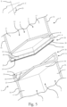
- FIG 2 illustrates a perspective view of the floating module shown in figure 1 .
- the floating module 1 also extends in a plane E, called the second plane E, comprising the transverse axis Y and the vertical axis Z, the second plane E thus being perpendicular to the longitudinal and vertical plane D, called foreground D.
- the floating module 1 comprises an upper part 50 intended to be oriented vertically upwards when the floating module 1 is used on a body of water.
- the floating module thus also comprises a lower part 51 located opposite the floating module 1 relative to the upper part 50 along the vertical axis Z, the lower part being intended to be immersed when the floating module 1 is implemented on a body of water.
- the upper part 50 comprises an upper wall 52 extending mainly in a third plane F comprising the transverse axis Y and the longitudinal axis X.
- the lower part 51 comprises a lower wall 53 extending mainly in the third plane F.
- the floating module 1 comprises a first side wall 54 and a second side wall 55 extending mainly in the first plane D.
- the first side wall 54, the second side wall 55, the upper wall 52 and the lower wall 53 are arranged in so that the first side wall 54 and the second side wall 55 are interconnected by the upper wall 52 and the lower wall 53, the upper wall 52 and the lower wall 53 being connected together by the first side wall 54 and the second side wall 55.
- the upper wall 52, the lower wall 53, the first side wall 54 and the second side wall 55 can in particular each form a wall 2 within the meaning of the invention.
- the lower wall 53, the first side wall 54 and the second side wall 55 each include an extension 14.
- the upper wall 52 has no extension, the upper wall 52 thus forming a passage 56, making it possible in particular to facilitate access for an operator to a space located between the floating module and a second floating module intended to be assembled to form a floating structure.
- FIG. 3 is a detailed view, in section, at the level of the first longitudinal termination 26 of the floating module 1 illustrated in figures 1 And 2 .
- the extension 14 and the edge 11 of the wall are arranged so that the external face 16 of the wall and an internal face 20 of the extension 14, said internal face 20 of the extension being oriented towards the cavity 18, are in the same plane P.
- the cavity 18 extends along a first dimension 30 measured between the internal face 20 of the extension and a plane P formed by the internal face 17 of the wall 2 from which the extension 14 emerges.
- the wall 2 extends along a second dimension 32 measured between its external face 17 and its internal face 16, the second dimension 32 thus corresponding to the thickness of the wall 2, the first dimension 30 being equal to the second dimension 32.
- the internal face of the extension and the external face of the wall are in the same plane P as long as the difference between the first dimension 30 and the second dimension 32 does not exceed 5% of the second dimension 32.
- the first dimension 30 is greater than the second dimension 32.
- the extension extends more peripherally and the minimum thickness necessary to ensure the continuity of material between two modules adjacent floating areas is ensured.
- the material intended to fill the cavity 18 makes it possible to extend the wall 2 longitudinally along the entirety of the second dimension of the wall 2, in other words along the entirety of the thickness of the wall.
- this configuration allows, when the floating module 1, called the first floating module, is assembled with an adjacent floating module, called the second floating module, to form a floating structure conforming to the second aspect of the invention, to ensure total mechanical continuity between the first floating module and a second floating module, and to obtain a modular floating structure which behaves like a monolithic structure having the same mechanical resistance as the current section of a floating module to resist mechanical forces, particularly in compression, by the material filling the cavity, and more particularly the entirety of the cavity 18 according to the first dimension 30 of said cavity.
- a sealing device 102 is located on a longitudinal end 111 of the first extension 29.
- the sealing device 102 is in particular a seal intended to be compressed between a first floating module and a second floating module in order to ensure sealing. of a space located between the first floating module and the second floating module.
- This sealing device 102 can be integral with the first floating module or the second floating module.
- the metal frame 22 extends longitudinally projecting from the first longitudinal end 4 of the wall.
- the prestressing sheath 24 extends longitudinally projecting from the first longitudinal end 4 of the wall, and in particular inside the wall, the prestressing sheath thus opening into the cavity 18.
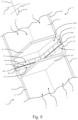
- THE figures 4 And 5 illustrate a partial view, respectively in section and in perspective, of an exemplary embodiment of a first floating module 3 and a second floating module 5 intended to be assembled in order to form a floating structure.
- the figures 3 And 4 illustrate the alignment step of the assembly process according to the third aspect of the invention.
- the first floating module and the second floating module are represented in the figure 4 in a third plane F comprising the longitudinal axis X and the transverse axis Y.
- the figure 4 is a sectional view from above of the first floating module and the second floating module.
- a first longitudinal termination 26 of the first floating module is placed opposite a second longitudinal termination 28 of the second floating module.
- a cavity of the first floating module called the first cavity 19
- a cavity of the second floating module called the second cavity 21.
- the first extension 29 of the first floating module 3 faces the second extension 31 of the second floating module 5.
- the first stops 33 of the first floating module 3 face the second stops 35 of the second floating module 5, the first stops 33 being distant from the second stops 35 of the second floating module 5.
- each prestressing sheath 24 coming from the first floating module 3, called the first prestressing sheath faces a prestressing sheath 24 coming from the second floating module 5, called the second prestressing sheath, to which it is intended to be coupled.
- each metal frame 22 from the first floating module 3, called the first metal frame faces a metal frame 22 from the second floating module 5, called the second metal frame, to which it is intended to be coupled.
- FIG. 6 is a partial view of an exemplary embodiment of a first floating module 3 and a second floating module 5 during assembly.
- the Figure 6 illustrates the removable coupling step of the assembly method according to the third aspect of the invention.
- the first floating module 3 and the second floating module 5 are illustrated according to the first longitudinal and vertical plane D, the Figure 6 thus representing a side view of the first floating module 3 and the second floating module 5.
- a connecting frame 110 ensures the position of the first floating module 3 relative to the second floating module 5. More particularly, the connecting frame 110, forming a rigid structure, in particular formed by an at least partially metallic structure, is fixed on a wall 2, more particularly on an external face 16 of a wall, of the first floating module 3 and on a wall, more particularly on an external face 16 of a wall, of the second floating module 5. In the exemplary embodiment illustrated, the connecting frame 110 is fixed on the upper wall 52 of the first floating module 3 and on the upper wall 52 of the second floating module 5. The fixing of the connecting frame 110 on the second floating module 5 can be carried out prior to the fixing the connection frame 110 on the first floating module 3.
- the second floating module 5 is brought closer to the first floating module 3 in order to be flush with the latter so that the rimpedement between the first floating module 3 and the second floating module 5 is sufficient.
- the connecting frame 110 is then fixed on the second floating module 5, thus ensuring the relative position of the second floating module 5 relative to the first floating module 3.
- the connecting frame 110 can be fixed on the first floating module 3 and the second floating module 5 simultaneously, or substantially simultaneously, once the rimpedement between the first floating module 3 and the second floating module 5 is carried out.
- the sealing device 102 located at the first longitudinal end 26 of the first floating module 3, and inserted between the first extension 29 of the first floating module 3 and the second extension 31 of the second floating module 5, said sealing device 102 is compressed between the first extension 29 and the second extension 31.
- the first cavity 19 and the second cavity 21 form a hollow 104 delimited transversely by the first extension and the second extension, the hollow being delimited longitudinally by the edge 11 of a wall of the first floating module 3 and the edge 11 of a wall of the second floating module 5.
- the sealing device 102 also ensures the sealing of a space 106 delimited transversely by the first extension 29 and the second extension 31, the space 106 being delimited longitudinally by the first partition 8 of the first floating module 3 and by the second partition 10 of the second floating module 5.
- the hollow 104 corresponds to the sum of the first cavity 19 and the second cavity 21, while the space 106 corresponds to the volume delimited vertically by the extensions 14 and longitudinally by the partitions 8,10 of the first floating module 3 and the second floating module 5.
- the upper wall 52 of the first floating module 3 and the upper wall 52 of the second floating module 5 both being devoid of extension, thus forming the passage 56, thus allow access to the space 106, in particular for subsequent stages of the assembly of the first floating module 3 and the second floating module 5, such as a step of emptying the space 106, or even a step of mechanical connection between the metal frames of the first floating module 3 and the metal frames of the second module floating 5.
- the sealing device 102 ensuring the sealing of the space 106, in particular at the level of the side walls and the lower wall of the first floating module 3 and the second floating module 5, it is possible to carry out a draining step of said space 106.
- the first floating module 3 and the second floating module 5 being assembled on a body of water, and therefore each being partially submerged, water is thus present inside the space 106 when the first floating module 3 and the second floating module are brought closer to each other.
- the step of emptying space 106 therefore makes it possible to remove the water present in space 106, in order to carry out or facilitate subsequent stages of assembly between the first floating module 3 and the second floating module 5.
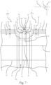
- THE figures 7 And 8 illustrate a view, respectively in section and in perspective, of the first floating module 3 and the second floating module 5 visible at the Figure 6 .
- Figure 7 illustrates the first floating module and the second floating module 5 in the third plane F, the figure 7 thus being a top view.
- the figures 7 And 8 illustrate a mechanical connection step between the first floating module 3 and the second floating module 5.
- the connection frame 110 is not shown.
- figure 7 illustrates a top view, that is to say according to the foreground
- the first floating module 3 and the second floating module 5 are connected to each other by a mechanical connection step between the first metal frame and the second metal frame.
- the mechanical connection between the first metal frame and the second metal frame is provided by a coupler 34, thus ensuring that the first floating module 3 and the second floating module 5 remain supported against each other.
- the connection between the first metal frame and the second metal frame ensures the transmission of mechanical forces, particularly traction, between the first floating module and the second floating module.
- each first prestressing sheath is connected to a second prestressing sheath by a hollow sleeve 36, ensuring the sealing of the interior of each prestressing sheath 24 while allowing communication between the interior of the first prestressing sheath and the interior of the second prestressing sheath, thus allowing the passage of the prestressing cable through said first prestressing sheath and said second prestressing sheath.
- the mechanical connection step also ensures that the approximation of the first floating module 3 relative to the second floating module 5 is sufficient. Indeed, the first floating module 3 is brought closer to the second floating module 5, in particular due to the connection between the first metal frames and the second metal frames by the coupler 34, so that the first stops 33 of the first floating module 3 come resting against the second stops 35 of the second floating module 5. Thus, the first stops 33 and second stops 35 make it possible to identify when the rimpedement between the first floating module 3 and the second floating module 5 is sufficient, in particular in order to ensure sufficient compression of the sealing device 102 interposed between the first floating module 3 and the second floating module 5, in order to ensure the sealing of the space 106.
- the mechanical connection step that is to say the connection of the first metal reinforcement to the second metal reinforcement by the coupler 34, as well as the connection between the first prestressing sheath and the second prestressing sheath by the sleeve 36, is facilitated if the emptying step has been carried out beforehand, in the case where the first floating module 3 and the second floating module 5 are assembled on a body of water.
- the thickness of the hollow 104 corresponding to the first dimension 30 of the cavity of the first floating module 3 as well as to the first dimension 30 of the cavity of the second floating module 5, is equal to the second dimension 32 of the wall 2 of the first floating module 3.
- the thickness of the hollow 104 is equal to a third dimension 32' of the wall of the second floating module 5, the third dimension 32' being measured between the external face 16 and the internal face 17 of the wall 2 of the second floating module 5.
- this configuration makes it possible to ensure total mechanical continuity between the first floating module and a second floating module, and to obtain a modular floating structure which behaves like a monolithic structure having the same mechanical resistance as the current section of a floating module, the floating structure thus presenting a continuity of material, along the entirety of the second dimension 32 and the third dimension 32' between the first floating module 3 and the second floating module 5 through the hollow 104, the hollow being intended to be filled with concrete, the thickness of the hollow 104 being equal to the second dimension 32 and the third dimension 32'.
- the trough is aligned along the vertical axis Z with the wall 2 of the first floating module and the wall 2 of the second floating module.
- the external face 16 of the wall of the first floating module 3 and the external face 16 of the wall 2 of the second floating module 5 are in the same plane, said plane also being the plane of extension of the internal face 20 of the first extension 29 of the first floating module 3 and the internal face 20 of the second extension 31 of the second floating module 5.
- the internal face 17 of the wall of the first floating module 3 and the internal face 17 of the wall 2 of the second floating module 5 are in the same plane.
- FIGS. 9 And 10 illustrate a partial view, respectively in section and in perspective, of an exemplary embodiment of a floating structure 100 conforming to the second aspect of the invention.
- FIG. 9 illustrates the floating structure 100 in the third plane F, the Figure 9 thus being a top view.
- the floating structure 100 illustrated is formed of at least the first floating module 3 and the second floating module 5 visible to the figures 7 And 8 .
- the coupler 34 and the sleeve 36 installed, as illustrated in figures 7 And 8 , thus providing the mechanical connection between the first floating module 3 and the second floating module 5, a material, in particular concrete, is poured into the hollow 104 so that the first floating module 3 and the second floating module 5 form a monolithic assembly . More particularly, the first longitudinal end 4 of the first floating module 3 is connected by the concrete poured in the hollow 104 to the second longitudinal end 6 of the second floating module 5.
- the hollow 104 being formed by the first cavity 19 and the second cavity 21, extends along the first dimension 30.
- the first dimension 30 being equal to the second dimension 32 corresponding to the thickness of the wall 2
- this configuration allows the concrete present in the hollow 104 to take up forces mechanical, particularly in compression, because it ensures total mechanical continuity between the first module floating and a second floating module, and to obtain a modular floating structure which behaves like a monolithic structure having the same mechanical resistance as the current section of a floating module, unlike a known configuration in which the first dimension of the hollow does not represents only a portion of the thickness of the wall.
- the prestressing sheath 24 opening into the hollow 104 is thus covered by the concrete present in the hollow.
- the prestressing cable 25 inserted inside the prestressing sheath 24 extends in the longitudinal axis of the wall of the first floating module 3 and of the wall of the second floating module 5, inside said walls , thus allowing the compressive force exerted by the tensile force applied to the prestressing cable to be centered in relation to the wall of the first floating module 3 and the wall of the second floating module 5, in particular in comparison with a known configuration in which the prestressing cable extends longitudinally on the external face or on the internal face of the wall of the first floating module and of the wall of the second floating module, the compressive force exerted by the tensile force applied to the prestressing cable then being eccentric.
- a floating structure 100 advantageously having an extension 14 defining a cavity 18 on each of its walls, has high resistance to mechanical forces in compression, provided by the concrete poured in each cavity 18, which makes it possible to ensure total mechanical continuity between the first floating module and a second floating module, and to obtain a modular floating structure which behaves like a monolithic structure having the same mechanical resistance as the current section of a floating module.
- each wall 2 of the first floating module 3 being connected to a wall 2 of the second floating module 5 by a concrete hollow 104 crossed by a metal frame 22 and/or a prestressing sheath 24 inside which there is a tensioned prestressing cable 25, the floating structure 100 has a high resistance to the shearing and bending movements which are exerted between the first floating module 3 and the second floating module 5, in particular due to the movements caused by waves at the level of the body of water on which the floating structure 100 rests.
- THE figures 11a and 11b illustrate a first assembly mode and a second assembly mode, respectively, between a first floating module 3 and a second floating module 5 intended to be assembled to form a floating structure 100.
- the figures 11a and 11b illustrate top views, along the third plane F, of the first floating module 3, the second floating module 5 and the floating structure 100.
- the figure 11a illustrates a substantially rectilinear floating structure 100 formed by a first floating module 3 and a second floating module 5 similar to each other, and extending mainly in the same direction.
- FIG 11b illustrates a floating structure 100 comprising an angle 57.
- the angle 57 formed is a right angle, that is to say whose value is equal to 90°, the angle being measured between the main extension axis of the first floating module 3 and the main extension axis of the second floating module 5 with which the first floating module 3 is assembled to form the floating structure 100.
- the floating structure is formed by a first floating module 3 and a second floating module 5, the first floating module 3 comprising the angle 57, the second floating module 5 being substantially rectilinear.
- the first floating module 3 thus comprises an extension 58 extending perpendicular to the main axis of extension of the first floating module 3.
- the second floating module 5 is connected to the extension 58 of the first floating module 3, thus allowing the formation of the floating structure 100 comprising the angle 57.
- This configuration thus makes it possible to obtain a wide variety of floating structure conformations, the angle not being limited to the value of 90° but being able to take any value, in particular between 90° ° and 180°, an angle of 180° then forming a rectilinear floating module.
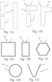
- THE figures 12a to 12e illustrate examples of embodiment of a floating structure 100 conforming to the second aspect of the invention. More particularly, the figures 12a to 12e each illustrate a form that a floating structure conforming to the second aspect of the invention can take, according to the third plane F. In other words, the figures 12a to 12e are top views of the floating structure 100 illustrated in each of said figures, each floating structure 100 comprising in particular several floating modules 1 conforming to the first aspect of the invention.
- the floating structures illustrated in figures 12a, 12b, 12c, 12d and 12e form, respectively, a square, a rectangle, a regular hexagon, a circle, and a floating structure taking approximately the shape of a “V”. It is understood that the floating structure 100 can take any other form without departing from the scope of the invention.
- the floating module comprises an extension emerging from the external face of a wall, the extension extending longitudinally projecting from a longitudinal end of the wall, the extension and the wall from which the extension comes being produced by continuity of material.
- the present invention makes it possible to connect two floating modules made of reinforced and prestressed concrete in water, so as to ensure total continuity of the concrete, reinforcements and prestressing steels between the two floating modules connected to each other with the same mechanical resistance as the current section of a floating module. It can be used to obtain a floating monolithic structure of any shape in concrete from a modular construction. The connection obtained is watertight and capable of resisting, for the different phases of the structure's life, the static and dynamic forces, the hydrodynamic forces, and the fatigue phenomena applied to it in accordance with international regulations.
- This invention can be used in the construction of bridges, oil platforms, ports, piers, floating platforms for renewable energies, in nuclear power and in any other field.
Landscapes
- Engineering & Computer Science (AREA)
- Mechanical Engineering (AREA)
- Ocean & Marine Engineering (AREA)
- General Engineering & Computer Science (AREA)
- Chemical & Material Sciences (AREA)
- Combustion & Propulsion (AREA)
- Civil Engineering (AREA)
- Structural Engineering (AREA)
- Environmental & Geological Engineering (AREA)
- Architecture (AREA)
- Bridges Or Land Bridges (AREA)
- Gyroscopes (AREA)
- Measuring Fluid Pressure (AREA)
- Pressure Sensors (AREA)
- Revetment (AREA)
- Lining Or Joining Of Plastics Or The Like (AREA)
Applications Claiming Priority (3)
| Application Number | Priority Date | Filing Date | Title |
|---|---|---|---|
| FR1859672A FR3087412B1 (fr) | 2018-10-19 | 2018-10-19 | Module flottant d'une structure flottante et procede d'assemblage de tels modules flottants |
| EP19769541.4A EP3867140B1 (de) | 2018-10-19 | 2019-09-20 | Schwimmmodul einer schwimmenden struktur und verfahren zur verbindung solcher schwimmenden module |
| PCT/EP2019/075403 WO2020078662A1 (fr) | 2018-10-19 | 2019-09-20 | Module flottant d'une structure flottante et procédé d'assemblage de tels modules flottants |
Related Parent Applications (2)
| Application Number | Title | Priority Date | Filing Date |
|---|---|---|---|
| EP19769541.4A Division EP3867140B1 (de) | 2018-10-19 | 2019-09-20 | Schwimmmodul einer schwimmenden struktur und verfahren zur verbindung solcher schwimmenden module |
| EP19769541.4A Division-Into EP3867140B1 (de) | 2018-10-19 | 2019-09-20 | Schwimmmodul einer schwimmenden struktur und verfahren zur verbindung solcher schwimmenden module |
Publications (2)
| Publication Number | Publication Date |
|---|---|
| EP4328386A2 true EP4328386A2 (de) | 2024-02-28 |
| EP4328386A3 EP4328386A3 (de) | 2024-03-13 |
Family
ID=65444003
Family Applications (2)
| Application Number | Title | Priority Date | Filing Date |
|---|---|---|---|
| EP23219703.8A Pending EP4328386A3 (de) | 2018-10-19 | 2019-09-20 | Schwimmende struktur und verfahren zur montage solch einer struktur |
| EP19769541.4A Active EP3867140B1 (de) | 2018-10-19 | 2019-09-20 | Schwimmmodul einer schwimmenden struktur und verfahren zur verbindung solcher schwimmenden module |
Family Applications After (1)
| Application Number | Title | Priority Date | Filing Date |
|---|---|---|---|
| EP19769541.4A Active EP3867140B1 (de) | 2018-10-19 | 2019-09-20 | Schwimmmodul einer schwimmenden struktur und verfahren zur verbindung solcher schwimmenden module |
Country Status (13)
| Country | Link |
|---|---|
| US (2) | US11932359B2 (de) |
| EP (2) | EP4328386A3 (de) |
| JP (2) | JP7465274B2 (de) |
| KR (1) | KR102739593B1 (de) |
| CN (1) | CN113226915B (de) |
| AU (2) | AU2019360540B2 (de) |
| BR (1) | BR112021007163A2 (de) |
| ES (1) | ES2981228T3 (de) |
| FR (1) | FR3087412B1 (de) |
| HR (1) | HRP20240608T1 (de) |
| PL (1) | PL3867140T3 (de) |
| RU (1) | RU2763089C1 (de) |
| WO (1) | WO2020078662A1 (de) |
Families Citing this family (2)
| Publication number | Priority date | Publication date | Assignee | Title |
|---|---|---|---|---|
| FR3140065A1 (fr) * | 2022-09-27 | 2024-03-29 | Safier Ingenierie | Plateforme flottante off-shore pour fabrication, assemblage, maintenance et/ou démontage d’éoliennes flottantes |
| FR3162040A1 (fr) * | 2024-05-07 | 2025-11-14 | Safier Ingenierie Sa | Module destiné à être au moins en partie immergé avec prolongement en saillie |
Family Cites Families (23)
| Publication number | Priority date | Publication date | Assignee | Title |
|---|---|---|---|---|
| US3091203A (en) * | 1958-10-27 | 1963-05-28 | Ernest M Usab | Concrete floating wharf sturctures |
| JPS423944Y1 (de) * | 1964-08-27 | 1967-03-07 | ||
| US3951085A (en) * | 1973-08-06 | 1976-04-20 | Johnson Don E | Floating structure arrangement |
| US4321882A (en) * | 1980-02-11 | 1982-03-30 | Builders Concrete, Inc. | Interconnecting system for marine floats |
| US4365914A (en) * | 1980-10-20 | 1982-12-28 | Builders Concrete, Inc. | Transverse post-tensioned tendon interconnecting system for marine floats |
| JPS6026998U (ja) * | 1983-08-01 | 1985-02-23 | 新日本製鐵株式会社 | 河床・湿地用フロ−タ作業台 |
| FR2597826B1 (fr) * | 1986-04-29 | 1991-01-04 | Gey Robert | Flotteur modulaire et procede d'assemblage d'une pluralite de tels flotteurs pour constituer un engin flottant |
| SU1446019A1 (ru) * | 1986-06-11 | 1988-12-23 | Предприятие П/Я А-1459 | Межпонтонный стык плавучего дока |
| US4793162A (en) * | 1986-08-07 | 1988-12-27 | Spt, Inc. | Method for repairing failed waterstops and products relating to same |
| US5107785A (en) * | 1990-12-07 | 1992-04-28 | Baxter Hal T | Floating dock and breakwater |
| JPH0791187A (ja) * | 1993-09-20 | 1995-04-04 | S T K Kk | 延熱防止構造 |
| US5915325A (en) * | 1997-04-15 | 1999-06-29 | Gerco, Inc. | Portable floating dock system |
| JP3698564B2 (ja) * | 1998-09-29 | 2005-09-21 | 鹿島建設株式会社 | シールドトンネルの接続部の構造 |
| JP2000328536A (ja) * | 1999-05-19 | 2000-11-28 | Hitachi Zosen Corp | Pcユニット型ハイブリッドケーソン |
| US6199502B1 (en) * | 1999-08-27 | 2001-03-13 | Jerry L. Mattson | Concrete module for floating structures and method of construction |
| JP2001200697A (ja) * | 2000-01-20 | 2001-07-27 | Tokyo Seiko Co Ltd | コンクリート構造物の接合方法 |
| EP1967654A4 (de) * | 2005-12-26 | 2014-03-05 | Kureha Ecology Man Co Ltd | Schwimmer und verbindungssystem davon |
| RU2550579C2 (ru) * | 2013-10-01 | 2015-05-10 | Российская Федерация, От Имени Которой Выступает Министерство Промышленности И Торговли Российской Федерации | Способ создания предварительного напряжения в районе соединения стыкуемых элементов предварительно напряженного железобетонного понтона |
| KR20140034886A (ko) * | 2014-02-27 | 2014-03-20 | (주)나다건설 | 연결 가능한 부유식 콘크리트 블록 및 부유식 콘크리트 블록 구조물 |
| KR101646712B1 (ko) * | 2014-08-13 | 2016-08-08 | 한국건설기술연구원 | 부잔교 함체의 수상 연결구조, 및 이러한 함체의 연결구조를 구비한 부잔교 |
| US9802677B2 (en) * | 2015-01-28 | 2017-10-31 | Charles Simola | Floating platform module |
| CN107487421A (zh) * | 2017-10-10 | 2017-12-19 | 罗庆杰 | 可一次浇筑成型模块化拼接的无底板混凝土浮台 |
| JP7467291B2 (ja) * | 2020-09-09 | 2024-04-15 | 大成建設株式会社 | コンクリート構造物の構築方法 |
-
2018
- 2018-10-19 FR FR1859672A patent/FR3087412B1/fr active Active
-
2019
- 2019-09-20 BR BR112021007163-6A patent/BR112021007163A2/pt active Search and Examination
- 2019-09-20 HR HRP20240608TT patent/HRP20240608T1/hr unknown
- 2019-09-20 KR KR1020217015050A patent/KR102739593B1/ko active Active
- 2019-09-20 JP JP2021546454A patent/JP7465274B2/ja active Active
- 2019-09-20 US US17/282,023 patent/US11932359B2/en active Active
- 2019-09-20 EP EP23219703.8A patent/EP4328386A3/de active Pending
- 2019-09-20 AU AU2019360540A patent/AU2019360540B2/en active Active
- 2019-09-20 PL PL19769541.4T patent/PL3867140T3/pl unknown
- 2019-09-20 ES ES19769541T patent/ES2981228T3/es active Active
- 2019-09-20 RU RU2021112969A patent/RU2763089C1/ru active
- 2019-09-20 CN CN201980068916.1A patent/CN113226915B/zh active Active
- 2019-09-20 EP EP19769541.4A patent/EP3867140B1/de active Active
- 2019-09-20 WO PCT/EP2019/075403 patent/WO2020078662A1/fr not_active Ceased
-
2024
- 2024-02-13 US US18/440,327 patent/US12263923B2/en active Active
- 2024-03-27 JP JP2024051700A patent/JP7699865B2/ja active Active
-
2025
- 2025-03-06 AU AU2025201641A patent/AU2025201641B2/en active Active
Also Published As
| Publication number | Publication date |
|---|---|
| AU2019360540B2 (en) | 2025-01-02 |
| JP2022508883A (ja) | 2022-01-19 |
| EP3867140C0 (de) | 2024-02-07 |
| ES2981228T3 (es) | 2024-10-07 |
| US11932359B2 (en) | 2024-03-19 |
| US12263923B2 (en) | 2025-04-01 |
| AU2025201641A1 (en) | 2025-03-27 |
| PL3867140T3 (pl) | 2024-07-08 |
| FR3087412B1 (fr) | 2021-04-02 |
| US20240208617A1 (en) | 2024-06-27 |
| EP3867140A1 (de) | 2021-08-25 |
| JP7465274B2 (ja) | 2024-04-10 |
| RU2763089C1 (ru) | 2021-12-27 |
| US20210347447A1 (en) | 2021-11-11 |
| EP4328386A3 (de) | 2024-03-13 |
| HRP20240608T1 (hr) | 2024-09-27 |
| WO2020078662A1 (fr) | 2020-04-23 |
| JP2024099521A (ja) | 2024-07-25 |
| KR102739593B1 (ko) | 2024-12-05 |
| FR3087412A1 (fr) | 2020-04-24 |
| CN113226915B (zh) | 2024-10-18 |
| AU2019360540A1 (en) | 2021-05-27 |
| CN113226915A (zh) | 2021-08-06 |
| JP7699865B2 (ja) | 2025-06-30 |
| KR20210079337A (ko) | 2021-06-29 |
| BR112021007163A2 (pt) | 2021-07-20 |
| AU2025201641B2 (en) | 2026-02-26 |
| EP3867140B1 (de) | 2024-02-07 |
Similar Documents
| Publication | Publication Date | Title |
|---|---|---|
| EP3867140B1 (de) | Schwimmmodul einer schwimmenden struktur und verfahren zur verbindung solcher schwimmenden module | |
| EP3320149B1 (de) | Formeinsatz und verblendblock mit solchem einsatz | |
| WO1995025864A1 (fr) | Panneau pour la realisation de bassins de retention | |
| EP3359744B1 (de) | Gründungsbauwerk | |
| EP0152367B1 (de) | Vorrichtung zum Herstellen von Fugen, im allgemeinen in Industriefussböden aus Beton | |
| FR2642109A1 (fr) | Structure creuse allongee et son procede de fabrication | |
| WO1997040233A1 (fr) | Paroi moulee a armature continue, procede de realisation d'une telle paroi et coffrage pour realiser cette paroi | |
| FR2788071A1 (fr) | Element modulaire coffrant pour paroi de batiment | |
| FR3043417B1 (fr) | Element-cadre prefabrique et procede de fabrication d'un tel element-cadre | |
| EP1956156B1 (de) | Anschluss zur Verbindung von zwei Platten einer Mauer mit verlorener Verschalung | |
| FR3068676A1 (fr) | Module pour corps mort pour l'ancrage d'une structure flottante | |
| EP1067254A1 (de) | Haube eines Bewehrungsanschlusskastens und Bewehrungsanschlusskasten mit einer solchen Haube | |
| WO2009098423A2 (fr) | Methode de realisation d'une structure alveolaire | |
| FR2652845A1 (fr) | Ensemble de construction. | |
| FR2489206A1 (fr) | Procede de realisation d'un element modulaire de construction et dispositif pour le mettre en oeuvre | |
| EP4647332A1 (de) | Modul für mindestens ein unterwasserteil mit vorstehender verlängerung | |
| FR2873727A1 (fr) | Procede pour limiter les ponts thermiques lors de l'edification de parois de construction mettant en oeuvre des armatures de reprise vissees | |
| FR3032986A1 (fr) | Bloc pour la construction de mur de soutenement. | |
| EP3546168A1 (de) | Vorrichtung zum formen einer schale für ein einschaliges poolbecken | |
| FR2537631A1 (fr) | Perfectionnements aux structures en beton precontraint | |
| FR2922917A1 (fr) | Dispositif d'interruption thermique pour plancher en beton | |
| FR2812323A1 (fr) | Piscine du type composee d'elements prefabriques en beton arme | |
| FR2912440A1 (fr) | Panneau prefabrique destine a former une paroi isolante d'un batiment,et procede de fabrication de ce panneau | |
| FR2463529A1 (fr) | Plate-forme isolante | |
| FR2916781A1 (fr) | Caisson de boite d'attente et boite d'attente integrant un tel caisson |
Legal Events
| Date | Code | Title | Description |
|---|---|---|---|
| PUAI | Public reference made under article 153(3) epc to a published international application that has entered the european phase |
Free format text: ORIGINAL CODE: 0009012 |
|
| STAA | Information on the status of an ep patent application or granted ep patent |
Free format text: STATUS: THE APPLICATION HAS BEEN PUBLISHED |
|
| REG | Reference to a national code |
Ref country code: DE Ref legal event code: R079 Free format text: PREVIOUS MAIN CLASS: E02B0003060000 Ipc: B63B0035380000 |
|
| PUAL | Search report despatched |
Free format text: ORIGINAL CODE: 0009013 |
|
| AC | Divisional application: reference to earlier application |
Ref document number: 3867140 Country of ref document: EP Kind code of ref document: P |
|
| AK | Designated contracting states |
Kind code of ref document: A2 Designated state(s): AL AT BE BG CH CY CZ DE DK EE ES FI FR GB GR HR HU IE IS IT LI LT LU LV MC MK MT NL NO PL PT RO RS SE SI SK SM TR |
|
| AK | Designated contracting states |
Kind code of ref document: A3 Designated state(s): AL AT BE BG CH CY CZ DE DK EE ES FI FR GB GR HR HU IE IS IT LI LT LU LV MC MK MT NL NO PL PT RO RS SE SI SK SM TR |
|
| RIC1 | Information provided on ipc code assigned before grant |
Ipc: E02B 3/06 20060101ALI20240208BHEP Ipc: B63B 35/38 20060101AFI20240208BHEP |
|
| STAA | Information on the status of an ep patent application or granted ep patent |
Free format text: STATUS: REQUEST FOR EXAMINATION WAS MADE |
|
| 17P | Request for examination filed |
Effective date: 20240913 |
|
| RBV | Designated contracting states (corrected) |
Designated state(s): AL AT BE BG CH CY CZ DE DK EE ES FI FR GB GR HR HU IE IS IT LI LT LU LV MC MK MT NL NO PL PT RO RS SE SI SK SM TR |
|
| GRAP | Despatch of communication of intention to grant a patent |
Free format text: ORIGINAL CODE: EPIDOSNIGR1 |
|
| STAA | Information on the status of an ep patent application or granted ep patent |
Free format text: STATUS: GRANT OF PATENT IS INTENDED |
|
| INTG | Intention to grant announced |
Effective date: 20260205 |