EP4314799B1 - Zerstörungsfreie prüfung einer probe - Google Patents
Zerstörungsfreie prüfung einer probe Download PDFInfo
- Publication number
- EP4314799B1 EP4314799B1 EP21729455.2A EP21729455A EP4314799B1 EP 4314799 B1 EP4314799 B1 EP 4314799B1 EP 21729455 A EP21729455 A EP 21729455A EP 4314799 B1 EP4314799 B1 EP 4314799B1
- Authority
- EP
- European Patent Office
- Prior art keywords
- specimen
- processing algorithm
- acoustic waves
- raw data
- processing
- Prior art date
- Legal status (The legal status is an assumption and is not a legal conclusion. Google has not performed a legal analysis and makes no representation as to the accuracy of the status listed.)
- Active
Links
Images

Classifications
-
- G—PHYSICS
- G01—MEASURING; TESTING
- G01N—INVESTIGATING OR ANALYSING MATERIALS BY DETERMINING THEIR CHEMICAL OR PHYSICAL PROPERTIES
- G01N29/00—Investigating or analysing materials by the use of ultrasonic, sonic or infrasonic waves; Visualisation of the interior of objects by transmitting ultrasonic or sonic waves through the object
- G01N29/04—Analysing solids
- G01N29/045—Analysing solids by imparting shocks to the workpiece and detecting the vibrations or the acoustic waves caused by the shocks
-
- G—PHYSICS
- G01—MEASURING; TESTING
- G01N—INVESTIGATING OR ANALYSING MATERIALS BY DETERMINING THEIR CHEMICAL OR PHYSICAL PROPERTIES
- G01N29/00—Investigating or analysing materials by the use of ultrasonic, sonic or infrasonic waves; Visualisation of the interior of objects by transmitting ultrasonic or sonic waves through the object
- G01N29/04—Analysing solids
- G01N29/07—Analysing solids by measuring propagation velocity or propagation time of acoustic waves
-
- G—PHYSICS
- G01—MEASURING; TESTING
- G01N—INVESTIGATING OR ANALYSING MATERIALS BY DETERMINING THEIR CHEMICAL OR PHYSICAL PROPERTIES
- G01N29/00—Investigating or analysing materials by the use of ultrasonic, sonic or infrasonic waves; Visualisation of the interior of objects by transmitting ultrasonic or sonic waves through the object
- G01N29/04—Analysing solids
- G01N29/12—Analysing solids by measuring frequency or resonance of acoustic waves
-
- G—PHYSICS
- G01—MEASURING; TESTING
- G01N—INVESTIGATING OR ANALYSING MATERIALS BY DETERMINING THEIR CHEMICAL OR PHYSICAL PROPERTIES
- G01N29/00—Investigating or analysing materials by the use of ultrasonic, sonic or infrasonic waves; Visualisation of the interior of objects by transmitting ultrasonic or sonic waves through the object
- G01N29/22—Details, e.g. general constructional or apparatus details
- G01N29/225—Supports, positioning or alignment in moving situation
- G01N29/226—Handheld or portable devices
-
- G—PHYSICS
- G01—MEASURING; TESTING
- G01N—INVESTIGATING OR ANALYSING MATERIALS BY DETERMINING THEIR CHEMICAL OR PHYSICAL PROPERTIES
- G01N29/00—Investigating or analysing materials by the use of ultrasonic, sonic or infrasonic waves; Visualisation of the interior of objects by transmitting ultrasonic or sonic waves through the object
- G01N29/22—Details, e.g. general constructional or apparatus details
- G01N29/24—Probes
- G01N29/2437—Piezoelectric probes
-
- G—PHYSICS
- G01—MEASURING; TESTING
- G01N—INVESTIGATING OR ANALYSING MATERIALS BY DETERMINING THEIR CHEMICAL OR PHYSICAL PROPERTIES
- G01N29/00—Investigating or analysing materials by the use of ultrasonic, sonic or infrasonic waves; Visualisation of the interior of objects by transmitting ultrasonic or sonic waves through the object
- G01N29/22—Details, e.g. general constructional or apparatus details
- G01N29/26—Arrangements for orientation or scanning by relative movement of the head and the sensor
- G01N29/265—Arrangements for orientation or scanning by relative movement of the head and the sensor by moving the sensor relative to a stationary material
-
- G—PHYSICS
- G01—MEASURING; TESTING
- G01N—INVESTIGATING OR ANALYSING MATERIALS BY DETERMINING THEIR CHEMICAL OR PHYSICAL PROPERTIES
- G01N29/00—Investigating or analysing materials by the use of ultrasonic, sonic or infrasonic waves; Visualisation of the interior of objects by transmitting ultrasonic or sonic waves through the object
- G01N29/44—Processing the detected response signal, e.g. electronic circuits specially adapted therefor
- G01N29/4445—Classification of defects
-
- G—PHYSICS
- G01—MEASURING; TESTING
- G01N—INVESTIGATING OR ANALYSING MATERIALS BY DETERMINING THEIR CHEMICAL OR PHYSICAL PROPERTIES
- G01N29/00—Investigating or analysing materials by the use of ultrasonic, sonic or infrasonic waves; Visualisation of the interior of objects by transmitting ultrasonic or sonic waves through the object
- G01N29/44—Processing the detected response signal, e.g. electronic circuits specially adapted therefor
- G01N29/46—Processing the detected response signal, e.g. electronic circuits specially adapted therefor by spectral analysis, e.g. Fourier analysis or wavelet analysis
-
- G—PHYSICS
- G01—MEASURING; TESTING
- G01N—INVESTIGATING OR ANALYSING MATERIALS BY DETERMINING THEIR CHEMICAL OR PHYSICAL PROPERTIES
- G01N2291/00—Indexing codes associated with group G01N29/00
- G01N2291/01—Indexing codes associated with the measuring variable
- G01N2291/011—Velocity or travel time
-
- G—PHYSICS
- G01—MEASURING; TESTING
- G01N—INVESTIGATING OR ANALYSING MATERIALS BY DETERMINING THEIR CHEMICAL OR PHYSICAL PROPERTIES
- G01N2291/00—Indexing codes associated with group G01N29/00
- G01N2291/04—Wave modes and trajectories
- G01N2291/044—Internal reflections (echoes), e.g. on walls or defects
Definitions
- the invention relates to a method for non-destructively testing a specimen by means of acoustic waves and a testing system.
- US 2019/234909 A1 relates to a method and device for detecting and characterizing a reflecting element in an object.
- acoustic waves are commonly used to probe man-made structures, such as slabs, pavements, walls, decks, piles or shafts, made from e.g. concrete, timber or metal.
- the structures may be categorized according to their geometry in plate-like structures, e.g. slabs, pavements, walls and decks, and pile-like structures, e.g. piles and shafts.
- Information retrieved about the structures includes a thickness of the (plate-like) structures, a length of the (pile-like) structures, and in general internal properties of the structures, e.g. flaws.
- Impact-echo is an NDT method based on the use of impact-generated stress (acoustic) waves that propagate through plate-like structures and are reflected by internal flaws and external surfaces.
- Impact-echo can be used on thin concrete structures including slabs, pavements, walls, or decks, to assess their thickness or to locate flaws such as cracks, delamination, voids, honeycombing and debonding.
- Steel ball impactors are generally used to generate the acoustic waves.
- the ball diameter is generally selected according to the structure expected thickness.
- IE relies on measuring multiple wave reflections in a short period of time. As a consequence, IE probes must be able to measure high frequencies, e.g. above 10 kHz and in particular up to approximately 30 kHz.
- the structural health state is then determined based on analysing the measured acoustic waves in the frequency domain.
- Pile integrity testing also referred to as low-strain dynamic test or low-strain integrity test
- PIT low-strain dynamic test or low-strain integrity test
- This method is mostly applied in civil engineering for health assessment of, but not limited to, timber shaft and concrete pile such as used in deep foundation.
- This method relies on impact-generated stress (acoustic) waves.
- the acoustic waves are generally generated with a hammer at the top of the pile next to the probe.
- the acquired signal shows the time of flight, i.e. the travel time, between the first impact and the waves reflected from the bottom of the pile or from any flaws in the pile.
- the waves are travelling a longer distance than in IE, and only few reflections are generally captured.
- PIT probes are typically performant at low frequencies, e.g. between 100 Hz and 10 kHz.
- the structural health state is then determined based on analysing the time domain waveform.
- the problem to be solved by the present invention is therefore to provide an improved method and device for non-destructively testing a specimen by means of acoustic waves, in particular to widen a range of applicability of such method and device, in particular to different types and geometries of the specimen.
- Both, plate-like and pile-like specimens may have an arbitrary shape in a horizontal plane, i.e. the plane spanned by the two horizontal dimensions.
- the shape in the horizontal plane may be round, rectangular or square.
- the shape in the horizontal plane in other words a cross-section in the horizontal plane, may be variable along the depth dimension.
- the measurement position and in particular also an impact position for generating the acoustic waves, are located on a measurement side of the specimen, which in particular essentially coincides with a horizontal plane.
- this problem is solved by a method for non-destructively testing a specimen by means of acoustic waves.
- the method comprises the steps of
- the acoustic waves When the acoustic waves propagate through the specimen, they are attenuated, reflected and scattered. These effects may be frequency-dependent, i.e. they may effect different frequency components of the acoustic waves differently.
- reflected acoustic waves For retrieving information about the specimen, e.g. a thickness of length of the specimen or material properties such as flaws or a speed of sound in the specimen, in particular reflected acoustic waves are processed. Such reflected waves may be reflected at one or several discontinuities in the specimen, e.g. flaws, layers or a boundary of the specimen. Accordingly, they are called single reflections and multiple reflections, respectively.
- dominant frequency components of the reflected waves may be in a range between 100 Hz and 30 kHz.
- the dominant frequency component of the reflected waves may be between 5 and 30 kHz, whereas for a typical pile-like specimen, the dominant frequency components may be between 100 Hz and 6 kHz, in particular due to a longer travel path and thus more attenuation of higher frequency components.
- the first processing algorithm may be suitable to retrieve information about a plate-like specimen.
- the first processing algorithm may be a algorithm used in Impact echo testing, e.g. a conventional IE algorithm.
- the second processing algorithm may be suitable to retrieve information about a pile-like specimen.
- the second processing algorithm may be a algorithm used in Pile integrity testing, e.g. a conventional PIT algorithm.
- the two types of algorithms are detailed in the next section.
- the raw data received from the testing device may be processed by the first and/or the second processing algorithm.
- the same testing device may be used for acquiring data both on a plate-like and a pile-like specimen.
- a requirement is that the device is sensitive for acoustic waves in the relevant frequency ranges as described above.
- An example device capable of acquiring suitable raw data is described below.
- the method is computer-implemented and provides the options to process the raw data to the user, e.g. by means of a GUI.
- the user may then be prompted to choose either the first or the second processing algorithm to process the raw data.
- the method may comprise a step of automatically selecting the first or second processing algorithm based on characteristic features of the raw data, e.g. a frequency range, a dominant frequency component or a travel time of a reflected wave in the data.
- the method may comprise processing the raw data by both, the first and the second processing algorithm. This may e.g. include displaying data processed by both algorithms, e.g. in frequency domain as well as in time domain, to the user, e.g. by means of a GUI.
- the first processing algorithm may be an algorithm adapted to process raw data acquired on a plate-like specimen, e.g. an IE algorithm.
- the first processing algorithm includes determining a frequency spectrum of the raw data, in particular by applying a Fourier transform to the raw data.
- the first processing algorithm may include using frequency components of the raw data with frequencies up to at least 15 kHz, in particular up to at least 20 kHz. This is due to the plate-like shape of the specimen with a depth dimension, along which a reflected wave propagates transversally through the specimen, being of the order of 1 cm or 10 cm up to 1 m.
- the first processing algorithm includes determining a dominant frequency component in the frequency spectrum.
- the dominant frequency component may in particular be defined as a maximum frequency component, i.e. the Fourier component with the highest amplitude, e.g. in a defined frequency range, e.g. between 5 and 30 kHz.
- the dominant frequency component may be determined by finding a maximum of an envelope or windowed average of the frequency spectrum, e.g. in the defined frequency range.
- the first processing algorithm may comprise determining a thickness of the specimen, in particular based on the dominant frequency component. This is particularly useful if the specimen has a plate-like shape with the acoustic waves propagating transversally to the plate-like shape.
- the second processing algorithm may include determining a length of the specimen based on the travel time of a single reflection of the acoustic waves. It is assumed that the specimen has a pile-like shape with the acoustic waves propagating along the longitudinal extension. The single reflection may then be effected at a bottom side of the specimen opposite to the measurement side or at a flaw within the specimen.
- a requirement for determining the length or thickness of the specimen from travel time or frequency measurements is that the speed of sound in the specimen is known.
- the speed of sound may be input as a standard value for the material of the specimen.
- the method may comprise estimating the speed of sound from travel time measurements over a known distance, e.g. along the measurement side between impactor and measurement position, or from the impact position through a specimen of known length and back to the measurement position.
- generating the acoustic waves may include triggering an automatic impactor to hit the specimen.
- Such impactor may comprise a spring loaded test weight.
- the method may further comprise determining the speed of sound in the specimen based on the known distance. In case, a direct arrival is evaluated, i.e. a surface wave propagating along the measurement surface, a correction factor needs to be applied to convert between surface wave speed and sound speed in the specimen.
- the method further comprises generating the acoustic waves at the impact position repetitively, thereby generating several raw signals, in particular several raw signals per measurement position.
- the several raw signals may then be averaged per measurement position, in particular before determining the travel time. This improves a signal-to-noise ratio of the data, such that arrival times of reflected waves, and hence the travel time, may be more precisely determined.
- a second aspect of the invention relates to a testing system comprising
- the system may comprise first processing means adapted to execute the first processing algorithm and second processing means adapted to execute the second processing algorithm.
- the testing system may comprise an automatic impactor as described above.
- the automatic impactor advantageously is in communication with the processing means, e.g. with the tablet computer.
- the automatic impactor is configured to send a trigger signal to the processing means when the impactor impacts on the specimen. This may be used as a starting time for determining the travel time.
- the method described above may be implemented by a computer program.
- the computer program may then comprise instructions to cause the testing system to execute the steps of the method.
- a third aspect (currently not claimed) relates to a testing device, in particular for the above testing system. All features described with respect to the system and the method are also meant to be applicable to the testing device, and vice versa.
- the testing device comprises
- the acoustic wave sensor may be any sensor suitable for measuring oscillations in the mentioned frequency range.
- the acoustic wave sensor is a piezo or MEMS accelerometer, in particular a capacitive MEMS accelerometer.
- MEMS accelerometer has a high sensitivity and covers the required frequency range.
- the raw data representing acoustic waves measured by the acoustic wave sensor may cover a frequency range from zero to at least 15 kHz, in particular to at least 20 kHz.
- the acoustic wave sensor is arranged on a flexible carrier or wires, in particular a flex print, in order to avoid a transmission of vibrations e.g. from the housing via the carrier to the sensor. Further, such carrier avoids that natural oscillations of the carrier are located in the required frequency range. In this respect, it is also advantageous that the flexible carrier extends along an impact direction of the contact element.
- the contact element may be mechanically decoupled from the housing via a damping element between the contact element and the housing.
- the damping element may attenuate an amplitude of oscillations of the housing by at least 50%, in particular at least 90%, before reaching the contact element.
- the damping element may comprise at least one O-ring, e.g. made of rubber.
- the damping element may comprise damping glue.
- the contact element may comprise a protrusion held in a corresponding notch of the housing.
- the protrusion extends from a circumferential side of the contact element. This facilitates a mechanically decoupled, but still splash- and dust-tight mounting of the contact element in the housing.
- the protrusion may be clamped in the notch by means of the damping element, in particular by at least one or two O-rings.
- a diameter of the contact element is between 10 and 50 mm, in particular between 20 and 30 mm.
- a height of the contact element may be between 5 and 15 mm.
- Such contact element does not have natural oscillations in the relevant frequency range, which otherwise would lead to spurious frequencies in the raw data.
- the protruding part of the contact element protrudes from the housing by at least 2 mm. This ensures that only the contact element - and not the housing - is in contact with the specimen, even when the testing device is pressed against the specimen to ensure a good coupling.
- the cavity advantageously has a slot-like shape, which in particular is adapted to a form factor of the acoustic wave sensor on the carrier.
- the cavity may have a width of 5 mm or less, in particular 3 mm or less, and a length of at least 10 mm. Further, the cavity may have a depth between 5 and 10 mm and/or have rounded edges.
- the acoustic wave sensor may be mounted to the cavity by means of a glob-top.
- the contact element is mounted to a first end of the housing, and the housing extends between the first and a second end.
- a part of the housing extending between the first and the second end may then have a diameter or width between 1 and 10 cm, in particular between 4 and 7 cm.
- a length of the part of the housing extending between the first and second end may be between 5 and 15 cm, in particular between 7 and 10 cm.
- Such housing has a small form factor, and is easily and safely gripped by one hand.
- the device does not comprise an actuator or impactor.
- the testing system may comprise an actuator or impactor in addition to the testing device.
- the actuator or impactor may be mounted in an impactor housing.
- the impactor housing may then be mounted to the testing device, advantageously in a defined distance, and in particular with a damping element between impactor housing and the testing device's housing in order to avoid that vibrations from the impactor reach the sensor, which would be detrimental to the measured data.
- the testing device further comprises a communication module, in particular a Bluetooth transmitter or other wireless transmitter, configured to transmit raw data representing acoustic waves measured by the acoustic wave sensor.
- the raw data may then be received by processing means, such as a laptop or tablet computer, and processed according to the above method.
- such testing device has a wide range of applicability.
- such device may be used to acquire data for IE as well as for PIT. This allows the user to buy, bring and maintain only one device, while being able to test plate-like as well as pile-like structures.
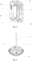
- Fig. 1 shows a perspective view of an embodiment of the testing device.
- the device comprises a housing 1, e.g. made of plastic.
- the housing 1 comprises knobs 12, e.g. in the form of Swiss crosses, which are advantageously made of plastic or rubber.
- the housing 1 comprises a fixation 11, e.g. in form of a loop, for mounting a ribbon, which may be used to safely hold the device.
- the device may comprise a button 13 configured to switch on and off the device.
- the button 13 may further be configured to control the acoustic wave sensor (not shown in Fig. 1 ), in particular the button 13 may be configured to trigger the acoustic wave sensor to start a measurement.
- This is advantageous, compared to other ways of triggering the measurement, e.g. measuring during the whole time in which the device is switched on, since only relevant data are acquired, which simplifies a processing of the data. In particular, it avoids the necessity to define a time window, wherein the relevant data are situated, during processing.
- the device may comprise an indicator, e.g. an LED, configured to indicate an operation state of the device, such as "on” or “measuring".
- an indicator e.g. an LED
- Such indicator may be included in the button 13.
- the button 13, facilitates a one-button control of the device as described before.
- the device further comprises a Bluetooth module 14 and a USB connector 15, both serving as communication modules, e.g. for transmitting measured raw data to a processing unit.
- the USB connector 15 may also be used to recharge a rechargeable battery forming a power supply of the device.
- Such rechargeable battery (see Fig. 2 ) may be replaced by opening the housing 1 via a knob 16.
- Fig. 2 shows the testing device of Fig. 1 with a side wall of the housing 1 removed. In particular, only a bottom part 23 and a top part 24 of the housing 1 are shown. Thus, interior elements of the device are visible.
- the device comprises a contact element 2, which, in this embodiment, has a plate-like shape and has an essentially round cross-section in a horizontal plane.
- the contact element 2 is made of steel and configured to mechanically couple to the specimen for measuring acoustic waves.
- the device further comprises a battery 22, e.g. a rechargeable battery as mentioned before, as power supply.
- a battery 22 e.g. a rechargeable battery as mentioned before, as power supply.
- a cut through the device is shown with the same elements as described above.
- Fig. 3 shows how the fixation 11 is formed by a recess in the housing 1 and a small rod through the recess, thereby forming a loop for e.g. mounting a ribbon.
- the contact element 2 comprises a protruding part, which protrudes from the housing 1 and in particular from the bottom part 23 of the housing, e.g. by at least 2 mm.
- the protruding part has a rounded shape, or alternatively may be conical. This ensures a good coupling of the contact element to the specimen.
- the contact element 2 comprises a cavity 25 in form of a slot for mounting the acoustic wave sensor (not shown in Fig. 3 ).
- a shape and dimensions of the cavity 25 are advantageously adapted to a shape and dimensions of the acoustic wave sensor. Typical dimensions are given above.
- Fig. 4 shows the bottom part 23 of the housing with the contact element 2 and the acoustic wave sensor 3 mounted on a flexible carrier 31 in the slot of the contact element 2.
- the sensor 3 is a MEMS accelerometer, which has a high sensitivity and a wide frequency range as described before.
- the sensor 3 may be of a different type, e.g. a piezoelectric sensor, configured to sense acoustic waves in the relevant frequency range, e.g. for testing plate-like and pile-like specimens, as described before.
- the senor 3 is mounted entirely in the cavity 25. In other words, no part of the sensor 3 protrudes from the cavity 25. Further, the sensor 3 is fixedly glued into the cavity, in particular to at least one side wall of the cavity parallel to the impact direction of the contact element 2. This may in particular be achieved by a glob-top over the sensor 3 and the cavity 25. Such way of mounting the sensor 3 in the contact element 2 avoids that the sensor 3 may pick up spurious frequencies, i.e. signals not representing acoustic waves in the specimen, e.g. from oscillations of the sensor 3 itself or of the carrier 31.
- the carrier 31 comprises leads to contact the acoustic wave sensor 3, and in particular connects the sensor 3 with the communication module and the battery. It is advantageous that the carrier 31 is flexible, e.g. a flex print, since this minimizes spurious oscillations, e.g. from the housing, propagated to the sensor 3 via the carrier.
- Fig. 5 shows a cut through the lower part of the device of the previous figures.
- the contact element 2 is mounted to the bottom part 23 of the housing via the fixation element 21.
- the contact element 2 comprises a circumferential protrusion 33, which is clamped to the housing, in particular to the bottom part 23, by the fixation element 21.
- the protrusion 33 may not extend around the entire circumference of the contact element 2, but only cover a part of the circumference.
- the contact element 2 may comprise several protrusions adapted to mount the contact element 2 to the housing.
- an O-ring 32 e.g. made from rubber, is arranged between the contact element 2 and the housing, in particular the bottom part 23 of the housing.
- Such O-ring represents a damping element and is adapted to attenuate oscillations propagating through the damping element, in particular oscillations coming from the housing.
- the damping element mechanically decouples the contact element 2 from the housing, at least to a certain degree, e.g. at least 50% or 90%.
- the O-ring 32 serves a sealing element for protecting the interior of the device, in particular making the housing splash- and dust-tight.
- each of the above described features contributes to making the testing device sensitive to acoustic waves over a wide range of frequencies, e.g. between 0 and 35 kHz, in particular between 100 Hz and 20 kHz.
- such device may be used to probe plate-like specimens, e.g. with an IE method and algorithm, as well as pile-like specimens, e.g. with a PIT method and algorithm, as described above.
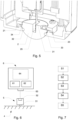
- Fig. 6 shows a testing system according to an embodiment.
- the testing system comprises a testing device 5, e.g. as described above.
- the testing device 5 comprises an acoustic wave sensor 51 configured to measure acoustic waves in mechanical contact with a specimen 4.
- the specimen 4 may have various shapes, e.g. plate-like or pile-like, and it may be of different materials, e.g. concrete, metal or timber.
- the device 5 is typically held against a surface of the specimen, e.g. by hand, in particular to establish a good coupling.
- advantageously putty or gel is applied between the testing device 5, in particular its contact element, and the surface of the specimen, for a better coupling.
- the contact element may in general be a dry-point contact, i.e. requiring no couplant such as putty or gel, which in particular needs to be pressed against the surface of the specimen.
- the system further comprises a processing unit 6 configured to receive and process raw data from the device 5.
- processing unit may e.g. be a laptop or a tablet computer, which is convenient to use in the field or on a test site.
- the processing unit 6 may be comprised in the device 5.
- the device 5 comprises a communication module 52, e.g. a Bluetooth transmitter, configured to transmit the raw data to a communication module 63 of the processing unit 6.
- device 5 and processing unit 6 may be connected by a cable, or the processing unit 6 may be an integral part of the testing device 5, i.e. arranged in the same housing.
- the processing unit 6 comprises first processing means 61 for carrying out a first processing algorithm, such as an IE algorithm, and second processing means 62 for carrying out a second processing algorithm, such as a PIT algorithm, as described above.
- the first and second processing means 61, 62 may be implemented e.g. as two separate or one common CPU or FPGA.
- the processing unit 6 may comprise a display 64 connected to the first and second processing means 61, 62 and configured to display a graphical representation of the raw data or processed data to the user.
- the processing unit 6 may be configured to carry out the method as described above and further detailed below with respect to Fig. 7 .
- testing system has the advantage that it may be used to probe specimens of different shapes and materials, in particular by applying different types of analysis to the raw data, e.g. in time domain as well as in frequency domain.
- the user only needs one testing system, i.e. one testing device plus processing unit, for performing NDT testing in the field or on a test site. This is more convenient than conventional solutions requiring at least two testing devices, and saves time and money.
- Fig. 7 shows an embodiment of the method for NDT testing of a specimen, as it may be implemented by means of the above-described system.
- preparation step S1 the system is set up. This may include switching the testing device on, establishing communication between the device and the processing unit and bringing the testing device in contact with the specimen at a measurement position.
- step S2 raw data representing acoustic waves that propagated through the specimen are received by the processing unit from the testing device.
- the acoustic waves typically include reflected waves, e.g. single or multiple reflections, which may be exploited to gain insight into the specimen, as described above.
- the acoustic waves are generated by an impactor, e.g. a manual hammer, impacting at an impact position near the measurement position, e.g. in a distance of 4 to 50 cm, in particular between 5 and 10 cm from the measurement position.
- the user may explicitly be provided with different options for processing the raw data, in particular with a first and second processing algorithm.
- the user may choose one of the processing algorithms, e.g. depending on a shape and/or material of the specimen.
- an applicable processing algorithm may be chosen automatically, e.g. based on features of the raw data, such as a frequency content or determined travel time.
- Step S4 comprises the actual processing of the raw data by at least one of the first and second processing algorithm.
- the processed data may be displayed to a user, e.g. via a GUI on a display of the processing unit.
- processing and displaying is done in real time, e.g. with a temporal delay to receiving the raw data of less than 10 s or even less than 1 s.
- the user may evaluate the acquired data directly in the field, and, if necessary, discard them and repeat the measurement.
- the method may comprise displaying the raw data and/or processed data in time domain as well as in frequency domain to the user, e.g. simultaneously.
- the method may include processing steps adjustable by the user, such as a filtering step or windowing step, in order to improve signal quality and receive better results, e.g. a more accurate estimate of the thickness or length of the specimen or more information about defects in the specimen.
- processing steps adjustable by the user such as a filtering step or windowing step, in order to improve signal quality and receive better results, e.g. a more accurate estimate of the thickness or length of the specimen or more information about defects in the specimen.
Landscapes
- Physics & Mathematics (AREA)
- Immunology (AREA)
- General Physics & Mathematics (AREA)
- Pathology (AREA)
- Analytical Chemistry (AREA)
- Health & Medical Sciences (AREA)
- Life Sciences & Earth Sciences (AREA)
- General Health & Medical Sciences (AREA)
- Biochemistry (AREA)
- Chemical & Material Sciences (AREA)
- Acoustics & Sound (AREA)
- Engineering & Computer Science (AREA)
- Signal Processing (AREA)
- Mathematical Physics (AREA)
- Spectroscopy & Molecular Physics (AREA)
- Investigating Or Analyzing Materials By The Use Of Ultrasonic Waves (AREA)
Claims (16)
- Verfahren zur zerstörungsfreien Prüfung einer Probe mittels akustischer Wellen, umfassend die folgenden Schritte- (S2) Empfangen von Rohdaten, die akustische Wellen darstellen, die sich durch die Probe (4) ausgebreitet haben, von einem Prüfgerät (5) an einer Messposition, die in mechanischem Kontakt mit der Probe (4) steht,- (S3) Bereitstellen von Optionen zur Verarbeitung der Rohdaten durch mindestens einen ersten und einen zweiten Verarbeitungsalgorithmus,- (S4) Verarbeiten der Rohdaten durch mindestens einen des ersten und zweiten Verarbeitungsalgorithmus,wobei der erste Verarbeitungsalgorithmus das Ableiten von Informationen über die Probe (4) aus Mehrfachreflexionen der akustischen Wellen umfasst,wobei der zweite Verarbeitungsalgorithmus das Ableiten von Informationen über die Probe (4) aus einer Laufzeit einer einzelnen Reflexion der akustischen Wellen umfasst,dadurch gekennzeichnet, dass der erste Verarbeitungsalgorithmus die Bestimmung eines Frequenzspektrums der Rohdaten umfasst.
- Das Verfahren nach Anspruch 1,
wobei die Bestimmung des Frequenzspektrums der Rohdaten die Anwendung einer Fourier-Transformation auf die Rohdaten beinhaltet. - Das Verfahren nach einem der vorhergehenden Ansprüche,
wobei der erste Verarbeitungsalgorithmus die Verwendung von Frequenzkomponenten der Rohdaten mit Frequenzen bis zu mindestens 15 kHz, insbesondere bis zu mindestens 20 kHz, umfasst. - Das Verfahren nach einem der Ansprüche 2 bis 3,
wobei der erste Verarbeitungsalgorithmus die Bestimmung einer dominanten Frequenzkomponente im Frequenzspektrum umfasst. - Das Verfahren nach Anspruch 4, ferner umfassend die folgenden Schritte- Empfangen von Rohdaten von mehreren verschiedenen Messpositionen von der Prüfeinrichtung (5) und- Zusammenstellen eines Datensatzes, der die dominante Frequenzkomponente pro Messposition enthält,- insbesondere Darstellen des Datensatzes als Heatmap.
- Das Verfahren nach Anspruch 5, umfassend ferner den Schritt- Erkennen einer abweichenden dominanten Frequenzkomponente, die von anderen dominanten Frequenzkomponenten im Datensatz abweicht,- und insbesondere Zuordnen der abweichenden dominanten Frequenzkomponente zu einem an der entsprechenden Messposition befindlichen Defekt.
- Das Verfahren nach einem der vorhergehenden Ansprüche,wobei der erste Verarbeitungsalgorithmus die Bestimmung einer Dicke der Probe (4) umfasst, insbesondere auf der Grundlage der dominanten Frequenzkomponente,insbesondere wobei die Probe (4) eine plattenartige Form hat und die akustischen Wellen sich quer zur plattenartigen Form ausbreiten.
- Das Verfahren nach einem der vorhergehenden Ansprüche,
wobei der zweite Verarbeitungsalgorithmus die Auswertung der Rohdaten im Zeitbereich umfasst. - Das Verfahren nach einem der vorhergehenden Ansprüche,
wobei der zweite Verarbeitungsalgorithmus die Verwendung von Frequenzkomponenten der Rohdaten mit Frequenzen bis zu 10 kHz und insbesondere über 100 Hz umfasst. - Das Verfahren nach einem der vorhergehenden Ansprüche,wobei der zweite Verarbeitungsalgorithmus die Bestimmung einer Länge der Probe (4) auf der Grundlage der Laufzeit umfasst,insbesondere wobei die Probe (4) eine pfahlartige Form hat und sich die akustischen Wellen entlang einer Längserstreckung der pfahlartigen Form ausbreiten.
- Das Verfahren nach einem der vorhergehenden Ansprüche, umfassend ferner- Erzeugen der akustischen Wellen an einer Aufschlagposition auf der Probe (4), insbesondere durch Aufschlagen eines Impaktors auf die Probe.
- Das Verfahren nach Anspruch 11,
wobei das Erzeugen der akustischen Wellen das manuelle Schlagen auf die Probe (4), insbesondere mit einem Schlaghammer, umfasst. - Das Verfahren nach Anspruch 11,wobei das Erzeugen der akustischen Wellen das Auslösen eines automatischen Impaktors zum Auftreffen auf die Probe (4) umfasst,insbesondere wobei sich die Aufschlagposition in einem bekannten Abstand von der Messposition befindet, undinsbesondere wobei das Verfahren umfasst- Bestimmen einer Schallgeschwindigkeit in der Probe (4) auf Grundlage des bekannten Abstands.
- Das Verfahren nach einem der Ansprüche 11 bis 13, ferner umfassend- wiederholtes Erzeugen der akustischen Wellen an der Aufschlagposition, dadurch Erzeugen mehrerer Rohsignale,- Mittelwertbildung über mehrere Rohsignale an einer Messposition, insbesondere vor der Bestimmung der Laufzeit.
- Ein Prüfsystem umfassend- ein Prüfgerät (5) mit einem Sensor (3, 51) für akustische Wellen,- Mittel (6), die eingerichtet sind, die Schritte des Verfahrens nach einem der vorhergehenden Ansprüche auszuführen,- insbesondere erste Verarbeitungsmittel (61), die zur Ausführung des ersten Verarbeitungsalgorithmus eingerichtet sind, und zweite Verarbeitungsmittel (62), die zur Ausführung des zweiten Verarbeitungsalgorithmus eingerichtet sind.
- Computerprogramm umfassend Anweisungen, die das Prüfsystem nach Anspruch 15 veranlassen, die Schritte des Verfahrens nach einem der Ansprüche 1 bis 14 auszuführen.
Applications Claiming Priority (1)
| Application Number | Priority Date | Filing Date | Title |
|---|---|---|---|
| PCT/EP2021/063910 WO2022248026A1 (en) | 2021-05-25 | 2021-05-25 | Method for ndt testing a specimen |
Publications (3)
| Publication Number | Publication Date |
|---|---|
| EP4314799A1 EP4314799A1 (de) | 2024-02-07 |
| EP4314799B1 true EP4314799B1 (de) | 2025-04-23 |
| EP4314799C0 EP4314799C0 (de) | 2025-04-23 |
Family
ID=76250311
Family Applications (1)
| Application Number | Title | Priority Date | Filing Date |
|---|---|---|---|
| EP21729455.2A Active EP4314799B1 (de) | 2021-05-25 | 2021-05-25 | Zerstörungsfreie prüfung einer probe |
Country Status (6)
| Country | Link |
|---|---|
| US (1) | US20240241084A1 (de) |
| EP (1) | EP4314799B1 (de) |
| JP (1) | JP2024519419A (de) |
| CN (1) | CN117425826A (de) |
| CA (1) | CA3219903A1 (de) |
| WO (1) | WO2022248026A1 (de) |
Family Cites Families (14)
| Publication number | Priority date | Publication date | Assignee | Title |
|---|---|---|---|---|
| US3554013A (en) * | 1969-07-22 | 1971-01-12 | Branson Instr | Pulse-echo ultrasonic thickness gauge with error prevention circuit |
| JPS57100306A (en) * | 1980-12-13 | 1982-06-22 | Nippon Doro Kodan | Method for measuring buried pile length |
| JP2581916B2 (ja) * | 1987-04-03 | 1997-02-19 | 株式会社 東横エルメス | コンクリ−トの厚さ又は内在ひび割れ深度の測定方法 |
| JP3156012B2 (ja) * | 1992-05-26 | 2001-04-16 | 株式会社東横エルメス | コンクリート構造物の厚さ測定方法 |
| JP2006319592A (ja) * | 2005-05-12 | 2006-11-24 | Honda Electronic Co Ltd | 超音波センサ |
| CN204370485U (zh) * | 2014-12-31 | 2015-06-03 | 广东天信电力工程检测有限公司 | 一种新型低应变激振力棒 |
| JP6826373B2 (ja) * | 2016-03-02 | 2021-02-03 | 古河機械金属株式会社 | 検査装置 |
| US10234375B2 (en) * | 2016-09-15 | 2019-03-19 | Saudi Arabian Oil Company | Integrated ultrasonic testing and cathodic protection measurement probe |
| FR3057357B1 (fr) * | 2016-10-12 | 2019-04-19 | Commissariat A L'energie Atomique Et Aux Energies Alternatives | Procede et dispositif de detection et de caracterisation d'un element reflecteur dans un objet |
| JP2018128278A (ja) * | 2017-02-06 | 2018-08-16 | 公益財団法人鉄道総合技術研究所 | 打音検査装置及び打撃検査システム |
| RU2657325C1 (ru) * | 2017-06-05 | 2018-06-13 | Общество с ограниченной ответственностью "Акустические Контрольные Системы" | Способ ультразвукового контроля объектов из твёрдых материалов, ультразвуковой высокочастотный преобразователь для его реализации (варианты) и антенная решётка с применением способа |
| JP7115045B2 (ja) * | 2018-06-04 | 2022-08-09 | 株式会社大林組 | 杭の健全性評価方法 |
| JP6806836B2 (ja) * | 2019-04-26 | 2021-01-06 | 西日本技術開発株式会社 | コンクリート基礎の健全性評価方法 |
| JP6773878B1 (ja) * | 2019-12-19 | 2020-10-21 | 中日本ハイウェイ・エンジニアリング東京株式会社 | コンクリート構造物内部状況点検方法及びその方法に使用するシステム |
-
2021
- 2021-05-25 WO PCT/EP2021/063910 patent/WO2022248026A1/en not_active Ceased
- 2021-05-25 CN CN202180098594.2A patent/CN117425826A/zh active Pending
- 2021-05-25 US US18/563,963 patent/US20240241084A1/en active Pending
- 2021-05-25 JP JP2023572937A patent/JP2024519419A/ja active Pending
- 2021-05-25 EP EP21729455.2A patent/EP4314799B1/de active Active
- 2021-05-25 CA CA3219903A patent/CA3219903A1/en active Pending
Also Published As
| Publication number | Publication date |
|---|---|
| WO2022248026A1 (en) | 2022-12-01 |
| EP4314799A1 (de) | 2024-02-07 |
| CN117425826A (zh) | 2024-01-19 |
| US20240241084A1 (en) | 2024-07-18 |
| CA3219903A1 (en) | 2022-12-01 |
| EP4314799C0 (de) | 2025-04-23 |
| JP2024519419A (ja) | 2024-05-13 |
Similar Documents
| Publication | Publication Date | Title |
|---|---|---|
| CA3007067C (en) | Method and apparatus for non-destructive measurement of modulus of elasticity and/or the compressive strength of masonry samples | |
| KR101955440B1 (ko) | 초음파 음향속도 차이를 이용한 동탄성 계수 및 잔류응력 측정 시험평가 장치 | |
| EP1312916B1 (de) | Vorrichtung zur zerstörungsfreien akustischen inspektion | |
| US8468889B2 (en) | Apparatus for the non-destructive testing of samples using ultrasonic waves | |
| JP2018119845A (ja) | 内部欠陥の探査方法 | |
| Montiel-Zafra et al. | Monitoring the internal quality of ornamental stone using impact-echo testing | |
| JP5450177B2 (ja) | グラウト充填度の非破壊検査方法及び非破壊検査装置 | |
| EP4314799B1 (de) | Zerstörungsfreie prüfung einer probe | |
| KR100542651B1 (ko) | 비선형 음향반응을 이용한 비파괴 음향 탐사방법 | |
| Santhanam et al. | Reflection and transmission of fundamental Lamb wave modes obliquely incident on a crack in a plate | |
| JP2003329656A (ja) | コンクリート吹付法面の密着度診断法とその装置 | |
| JP3740547B2 (ja) | 木材応力波非破壊試験の方法 | |
| JP2000002692A (ja) | コンクリート構造物中或いはコンクリート構造物背後の欠陥探査方法 | |
| WO2023247055A1 (en) | System for non-destructively testing a specimen | |
| KR102106940B1 (ko) | 배음 진동자를 이용한 초음파 비파괴 검사 장치 | |
| RU2214590C2 (ru) | Способ определения физико-механических характеристик полимерных композиционных материалов и устройство для его осуществления | |
| Lu | Non-destructive evaluation on concrete materials and structures using cement-based piezoelectric sensor | |
| JPH06242086A (ja) | 超音波検査装置 | |
| Manthei | Characterisation of acoustic emission sensors | |
| Gao et al. | New developments in EMAT techniques for surface inspection | |
| AKBAROV et al. | DEVELOPMENT OF TESTING USING NON-DESTRUCTIVE TESTING METHODS | |
| JP2003035703A (ja) | コンクリート構造物の非破壊検査装置 | |
| Fry et al. | Evaluation of Anisotropy in Additively Manufactured Materials Using Resonant Ultrasound Spectroscopy | |
| JPH0328757A (ja) | 高ダンピング探触子 | |
| Cannas et al. | Numerical Simulations of Ultrasonic Non Destructive Techniques of Masonry Buildings. |
Legal Events
| Date | Code | Title | Description |
|---|---|---|---|
| STAA | Information on the status of an ep patent application or granted ep patent |
Free format text: STATUS: UNKNOWN |
|
| STAA | Information on the status of an ep patent application or granted ep patent |
Free format text: STATUS: THE INTERNATIONAL PUBLICATION HAS BEEN MADE |
|
| PUAI | Public reference made under article 153(3) epc to a published international application that has entered the european phase |
Free format text: ORIGINAL CODE: 0009012 |
|
| STAA | Information on the status of an ep patent application or granted ep patent |
Free format text: STATUS: REQUEST FOR EXAMINATION WAS MADE |
|
| 17P | Request for examination filed |
Effective date: 20231031 |
|
| AK | Designated contracting states |
Kind code of ref document: A1 Designated state(s): AL AT BE BG CH CY CZ DE DK EE ES FI FR GB GR HR HU IE IS IT LI LT LU LV MC MK MT NL NO PL PT RO RS SE SI SK SM TR |
|
| DAV | Request for validation of the european patent (deleted) | ||
| DAX | Request for extension of the european patent (deleted) | ||
| GRAP | Despatch of communication of intention to grant a patent |
Free format text: ORIGINAL CODE: EPIDOSNIGR1 |
|
| STAA | Information on the status of an ep patent application or granted ep patent |
Free format text: STATUS: GRANT OF PATENT IS INTENDED |
|
| INTG | Intention to grant announced |
Effective date: 20241205 |
|
| GRAS | Grant fee paid |
Free format text: ORIGINAL CODE: EPIDOSNIGR3 |
|
| GRAA | (expected) grant |
Free format text: ORIGINAL CODE: 0009210 |
|
| STAA | Information on the status of an ep patent application or granted ep patent |
Free format text: STATUS: THE PATENT HAS BEEN GRANTED |
|
| AK | Designated contracting states |
Kind code of ref document: B1 Designated state(s): AL AT BE BG CH CY CZ DE DK EE ES FI FR GB GR HR HU IE IS IT LI LT LU LV MC MK MT NL NO PL PT RO RS SE SI SK SM TR |
|
| REG | Reference to a national code |
Ref country code: GB Ref legal event code: FG4D |
|
| REG | Reference to a national code |
Ref country code: CH Ref legal event code: EP |
|
| REG | Reference to a national code |
Ref country code: DE Ref legal event code: R096 Ref document number: 602021029608 Country of ref document: DE |
|
| REG | Reference to a national code |
Ref country code: IE Ref legal event code: FG4D |
|
| U01 | Request for unitary effect filed |
Effective date: 20250423 |
|
| U07 | Unitary effect registered |
Designated state(s): AT BE BG DE DK EE FI FR IT LT LU LV MT NL PT RO SE SI Effective date: 20250430 |
|
| U20 | Renewal fee for the european patent with unitary effect paid |
Year of fee payment: 5 Effective date: 20250515 |
|
| PGFP | Annual fee paid to national office [announced via postgrant information from national office to epo] |
Ref country code: GB Payment date: 20250527 Year of fee payment: 5 |
|
| PGFP | Annual fee paid to national office [announced via postgrant information from national office to epo] |
Ref country code: CH Payment date: 20250601 Year of fee payment: 5 |
|
| PG25 | Lapsed in a contracting state [announced via postgrant information from national office to epo] |
Ref country code: ES Free format text: LAPSE BECAUSE OF FAILURE TO SUBMIT A TRANSLATION OF THE DESCRIPTION OR TO PAY THE FEE WITHIN THE PRESCRIBED TIME-LIMIT Effective date: 20250423 |
|
| PG25 | Lapsed in a contracting state [announced via postgrant information from national office to epo] |
Ref country code: NO Free format text: LAPSE BECAUSE OF FAILURE TO SUBMIT A TRANSLATION OF THE DESCRIPTION OR TO PAY THE FEE WITHIN THE PRESCRIBED TIME-LIMIT Effective date: 20250723 Ref country code: GR Free format text: LAPSE BECAUSE OF FAILURE TO SUBMIT A TRANSLATION OF THE DESCRIPTION OR TO PAY THE FEE WITHIN THE PRESCRIBED TIME-LIMIT Effective date: 20250724 |
|
| PG25 | Lapsed in a contracting state [announced via postgrant information from national office to epo] |
Ref country code: PL Free format text: LAPSE BECAUSE OF FAILURE TO SUBMIT A TRANSLATION OF THE DESCRIPTION OR TO PAY THE FEE WITHIN THE PRESCRIBED TIME-LIMIT Effective date: 20250423 |
|
| PG25 | Lapsed in a contracting state [announced via postgrant information from national office to epo] |
Ref country code: HR Free format text: LAPSE BECAUSE OF FAILURE TO SUBMIT A TRANSLATION OF THE DESCRIPTION OR TO PAY THE FEE WITHIN THE PRESCRIBED TIME-LIMIT Effective date: 20250423 |
|
| PG25 | Lapsed in a contracting state [announced via postgrant information from national office to epo] |
Ref country code: RS Free format text: LAPSE BECAUSE OF FAILURE TO SUBMIT A TRANSLATION OF THE DESCRIPTION OR TO PAY THE FEE WITHIN THE PRESCRIBED TIME-LIMIT Effective date: 20250723 |
|
| PG25 | Lapsed in a contracting state [announced via postgrant information from national office to epo] |
Ref country code: IS Free format text: LAPSE BECAUSE OF FAILURE TO SUBMIT A TRANSLATION OF THE DESCRIPTION OR TO PAY THE FEE WITHIN THE PRESCRIBED TIME-LIMIT Effective date: 20250823 |