EP4313634B1 - Verfahren zur bestimmung des verschleisszustands einer reifenseitenwand für stadtbusse - Google Patents
Verfahren zur bestimmung des verschleisszustands einer reifenseitenwand für stadtbusse Download PDFInfo
- Publication number
- EP4313634B1 EP4313634B1 EP22717865.4A EP22717865A EP4313634B1 EP 4313634 B1 EP4313634 B1 EP 4313634B1 EP 22717865 A EP22717865 A EP 22717865A EP 4313634 B1 EP4313634 B1 EP 4313634B1
- Authority
- EP
- European Patent Office
- Prior art keywords
- wear
- sidewall
- determining
- tyre
- state
- Prior art date
- Legal status (The legal status is an assumption and is not a legal conclusion. Google has not performed a legal analysis and makes no representation as to the accuracy of the status listed.)
- Active
Links
Images



Classifications
-
- B—PERFORMING OPERATIONS; TRANSPORTING
- B60—VEHICLES IN GENERAL
- B60C—VEHICLE TYRES; TYRE INFLATION; TYRE CHANGING; CONNECTING VALVES TO INFLATABLE ELASTIC BODIES IN GENERAL; DEVICES OR ARRANGEMENTS RELATED TO TYRES
- B60C11/00—Tyre tread bands; Tread patterns; Anti-skid inserts
- B60C11/24—Wear-indicating arrangements
- B60C11/246—Tread wear monitoring systems
-
- B—PERFORMING OPERATIONS; TRANSPORTING
- B60—VEHICLES IN GENERAL
- B60C—VEHICLE TYRES; TYRE INFLATION; TYRE CHANGING; CONNECTING VALVES TO INFLATABLE ELASTIC BODIES IN GENERAL; DEVICES OR ARRANGEMENTS RELATED TO TYRES
- B60C11/00—Tyre tread bands; Tread patterns; Anti-skid inserts
- B60C11/24—Wear-indicating arrangements
- B60C11/243—Tread wear sensors, e.g. electronic sensors
Definitions
- the present invention relates to a tire for a heavy vehicle for urban use, more particularly an urban bus, and has as its subject a method for determining the state of wear of a sidewall of such a tire.
- a tire consists of two sidewalls, which are two lateral portions connecting a tread to two beads.
- the tread is positioned around the circumference of the tire and is intended to be worn down as the tire rolls.
- the beads are intended to ensure the tire is mounted on a rim.
- a sidewall usually comprises, from the outside to the inside of the tire, at least one outer layer of rubber material, in contact with the atmospheric air and generally comprising, on an outer face, a set of hollow or raised markings, a carcass reinforcement comprising at least one layer of metal or textile reinforcements coated in a rubber material, and at least one inner layer of rubber material, intended to be in contact with the inflation gas when the tire is mounted and inflated on its rim.
- a wear indicator is generally a cavity dug into the outer sidewall layer, from an outer sidewall face, this cavity being able to be of variable shape.
- Various embodiments of such a wear indicator have been described, by way of examples, in the documents KR 101981887B1 , IT 2018 0000 3254 A1 , US 2021/031569 A1 , EP 3251958B1 , JP 2014180904A , WO 2013118657A1 , CN 201380726 , JP 2003200717A And EP 0726173B1 .
- any urban bus tire operator needs accurate monitoring of the tire sidewall wear condition, resulting in an estimate of the remaining operating life before the sidewall wears out completely. Incorrectly scheduled maintenance operations can also cause untimely vehicle downtime, resulting in additional operating costs.
- the inventors therefore set themselves the objective, for a tire for a heavy vehicle for urban use, in particular for an urban bus, of proposing a method for determining the state of wear of a sidewall of such a tire, making it possible to automate and make more reliable the measurement of the depth of the wear indicator at a given date, and therefore the estimation of the residual thickness of the outer layer of the sidewall, and to determine an estimation of the remaining operating life of the tire.
- the invention essentially aims to estimate the level of wear of a sidewall of a tire for an urban bus at any time during the life of the tire, as well as the expected date of maintenance of the tire, either by turning it over on the rim or by replacing the tire, and to communicate this information to the operator of the vehicle to enable him to plan his intervention.
- the given date Ti for determining the state of wear of the sidewall corresponds to a scheduled inspection date or to a mileage achieved or to a given level of wear of the tread of the tire. This determination takes place on a tire mounted on the vehicle and therefore concerns the sidewall positioned outside the vehicle.
- the step of capturing the state of the wear indicator is a step of taking a picture of the wear indicator by automatic optical means.
- the step of taking a picture of the wear indicator is carried out using an automatic optical means positioned perpendicular to the sidewall, such that a sidewall lighting system emits light rays included in an angle, centered on a normal to the sidewall passing through the center of rotation of the tire, at most equal to 60°.
- the shooting system is positioned substantially perpendicular to the side in an angular sector of at most 60°.
- the step of taking a picture of the wear indicator is carried out using an automatic optical means positioned tangentially to the sidewall, such that a sidewall lighting system emits light rays within an angle forming, with a tangent to the outer face of the sidewall, at most equal to 30°.
- the imaging system is positioned substantially tangentially to the sidewall in an angular sector of at most 30° relative to the tangent to the sidewall.
- the imaging system can be placed either on the side of the front part of the tread or on the side of the rear part of the tread, the tire being mounted on the vehicle.
- said wear indicator comprising means making it possible to determine its depth on the given date Ti, the step of determining the depth of the wear indicator is a step of observing and/or measuring the means of the wear indicator.
- a preferred embodiment of a wear indicator comprising means for determining its depth at the given date Ti, is a wear indicator having an emerging section on the outer flank face containing an inscribed circle whose diameter decreases continuously with wear of the flank, and having a non-smooth inner wall, comprising a distribution of elements in relief or indentation relative to the inner wall, and/or a texture in relief relative to the inner wall, such that said inner wall visually contrasts with the outer flank face.
- inscribed circle is meant a circle internally tangent to the contour of the emerging surface. The diameter of the circle, that is to say the portion of the emerging section which it delimits, decreases continuously as the outer flank layer is abrasiond.
- any wear indicator has a contour which may, for example, be circular, or be multi-lobed, i.e. comprising at least two lobes.
- the shape of this contour may change depending on the wear of the flank: for example, a multi-lobed contour in new condition can become circular from a certain level of wear.
- the determination of its depth at the given date Ti is therefore based on the measurement of the dimensions of its through section, characterized in particular by the diameter of the circle inscribed in said through section, and/or the analysis of the shape of its through section, said dimensions and/or said shape of the through section being correlated to a depth of the wear indicator.
- Knowing the average wear speed Vi of the wear indicator at the given date Ti makes it possible to know the wear kinetics of the sidewall, in the context of use of the tire.
- This average speed is calculated between the date Ti and a reference date Tr prior to Ti.
- the reference date Tr can be taken equal to the initial date T0 of fitting of the tire on the vehicle, the tire then being in a new condition, with an initial depth of wear indicator equal to P0.
- the step of estimating the forecast maintenance date Mi of the tire, at which the depth of the wear indicator Pi is zero is a step of determining the time ti, counted from the date Ti, at the end of which the depth of the wear indicator Pi is zero in the hypothesis of an average wear speed Vi of the wear indicator.
- Knowing the average wear speed Vi of the wear indicator at the given date Ti allows, by extrapolation assuming this speed to be constant, to determine the time required to reach a zero depth of the wear indicator, i.e. complete abrasion of the outer layer of the sidewall, with generally a residual thickness of material between the bottom of the wear indicator and the carcass reinforcement for its protection.
- the restitution step includes a display step on an interface intended for a user.
- a display step allows for a direct visual restitution to the user who is monitoring the tire, thus saving time.
- the restitution step includes information relating to a depth Pi of the wear indicator on the given date Ti.
- the restitution step preferably includes information relating to an estimate of the expected maintenance date at which the depth of the wear indicator is zero.
- the process of determining the state of wear of a tire sidewall includes a step of identifying the tire. It is indeed necessary to properly identify the tire, as an individual, to be able to monitor the evolution of its sidewall wear and decide whether to turn it over on the rim or replace it if necessary. Indeed, due to their respective manufacturing characteristics and their different positions on the vehicle, two tires generally have differentiated sidewall wear kinematics.
- the method for determining the state of wear of a tire sidewall comprises a step of identifying the tire by recognizing an individualized marking or by reading an RFID (Radio Frequency Identification Data) identifier of the tire.
- RFID Radio Frequency Identification Data
- an RFID (Radio Frequency Identification Data) identifier implanted in the tire, for example via an affixed label, contains tire identification data which can be read by suitable means.
- the method for determining the state of wear of a tire sidewall comprises a step of identifying the wear indicator on the identified tire.
- the wear of the sidewall is not necessarily uniform around the entire circumference of the sidewall. Under these conditions, it may be useful to have several wear indicators on the same sidewall, distributed around the circumference of the sidewall, to determine average wear of the sidewall: hence the interest in being able to identify each wear indicator to associate the measured wear characteristics with it.
- the method for determining the state of wear of a tire sidewall includes a step of transmitting captured information to a database. It is indeed advantageous to have a remote database, avoiding storing too much information locally.
- the invention also relates to a system for implementing the method for determining the state of wear of a tire sidewall according to any one of the embodiments of the method previously described.
- the system for implementing a method for determining the state of wear of a tire sidewall comprises means for displaying the state of wear of the sidewall.
- the capture means and/or the display means and/or the data transmission means and/or the analysis means are implemented by an optoelectronic device.
- FIG. 1 is a schematic representation of the device for determining the state of wear of a tire sidewall mounted on an urban bus.
- Figure 1 describes in particular the step of taking a picture of a wear indicator 6, formed in a sidewall 2 of the tire 1 by an automatic optical means 9.
- the automatic optical means 9 is placed near the sidewall 2, on the outside of the vehicle, to take the picture of the wear indicator 6.
- the automatic optical means 9 is placed at ground level, so as to photograph the entire sidewall of the tire when the vehicle is stationary. This positioning makes it possible in particular to see all the areas of the sidewall, therefore all the wear indicators that may be present, and to take into account the circumferential irregularities in the level of grating on the sidewall.
- real distance / image calibrations are possible in relation to the size of the wheel.
- the automatic optical means 9 allows the transmission of captured information (identifier of the tire, wear indicator ID, wear indicator depth, expected tire maintenance date) to a database.
- the automatic optical means 9 is positioned perpendicular to the sidewall 2, such that a system for illuminating the sidewall 2 emits light rays within an angle N, centered on a normal to the sidewall 2 passing through the center of rotation of the tire 1, at most equal to 60°.
- the automatic optical means 9 is positioned tangentially to the sidewall 2, such that a system for illuminating the sidewall 2 emits light rays within an angle R forming, with a tangent to the outer face of the sidewall 2, at most equal to 30°.
- the imaging system can be placed either on the side of the front part of the tread, or on the side of the rear part of the tread, the front and rear parts being defined relative to the direction of travel V of the vehicle.
- FIG. 3 is a perspective view of a tire 1 for an urban bus comprising a wear indicator 6.
- the tire 1 comprises two sidewalls 2 connecting a tread 3 intended to come into contact with a ground, respectively to two beads 4, intended to come into contact with a rim 5.
- FIG. 4 is a meridian sectional view of a tire 1 for an urban bus comprising a wear indicator 6.
- This view represents half of a meridian section of the tire.
- the sidewall 2 comprises, on an outer sidewall face 21 in contact with atmospheric air, a wear indicator 6 recessed in a layer of rubber material axially external to a carcass reinforcement 8 winding into each bead 4 mounted on the rim 5.
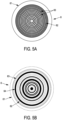
- FIG. 5A is a front view of a wear indicator 6 having a through section 61 with a circular outline with concentric circular grooves 63 in relief relative to the inner wall 62.
- FIG. 5B is a front view of a wear indicator 6 having a through section 61 with a circular outline combining concentric circular grooves 63 in relief relative to the inner wall 62 and a texture 64 between the grooves.
- FIG. 5C is a front view of a wear indicator 6 having a multi-lobed contour (4 lobes) through section 61 and an inner wall 62.
- the invention was more particularly studied in the case of a tire of dimension 275/70R22.5 X Incity Michelin, intended to equip an urban bus.
- the recommended inflation pressure is equal to 9 bars
- the recommended static load is equal to 3550 kg
- the recommended maximum speed is equal to 100 km/h.
- Two types of wear indicators formed in the sidewall of the study tire, were analyzed by applying the method for determining the state of wear of a sidewall, according to the invention: a first type of wear indicator having an emerging section with a circular contour, and a second type of wear indicator having an emerging section with a 4-lobe contour.
- the first type comprises circular grooves, distributed at a pitch equal to 2 mm and having a height equal to 0.5 mm and a thickness equal to 5 mm, and/or comprises a texture.
- the second type may or may not comprise a texture.
Landscapes
- Engineering & Computer Science (AREA)
- Mechanical Engineering (AREA)
- Tires In General (AREA)
- Length Measuring Devices With Unspecified Measuring Means (AREA)
Claims (15)
- Verfahren zur Bestimmung des Verschleißzustands einer Flanke (2) eines Reifens (1) für ein schweres Fahrzeug für den urbanen Einsatz:- wobei die Flanke (2) mindestens einen Verschleißanzeiger (6) umfasst, der in Bezug auf eine Flankenaußenseite vertieft ist, mit der atmosphärischen Luft in Kontakt ist und mit der Flankenaußenseite optisch kontrastiert,- wobei das Verfahren zur Bestimmung des Verschleißzustands der Flanke (2) gekennzeichnet ist durch:- einen Schritt des Erfassens des Zustands des Verschleißanzeigers (6) an einem gegebenen Datum Ti,- einen Schritt des Bestimmens der Tiefe Pi des Verschleißanzeigers (6) an dem gegebenen Datum Ti,- einen Schritt des Bestimmens der mittleren Verschleißgeschwindigkeit Vi des Verschleißanzeigers (6) an dem gegebenen Datum Ti,- einen Schritt des Schätzens des voraussichtlichen Wartungsdatums Mi des Reifens (1), an dem die Tiefe des Verschleißanzeigers (6) null ist,- einen Schritt des Ausgebens mindestens einer Information zum Verschleißzustand der Flanke (2) und zum voraussichtlichen Wartungsdatum Mi des Reifens (1).
- Verfahren zur Bestimmung des Verschleißzustands einer Flanke (2) eines Reifens (1) nach Anspruch 1, wobei der Schritt des Erfassens des Zustands des Verschleißanzeigers (6) ein Schritt des Aufnehmens des Verschleißanzeigers (6) mit einer automatischen optischen Einrichtung (9) ist.
- Verfahren zur Bestimmung des Verschleißzustands einer Flanke (2) eines Reifens (1) nach Anspruch 2, wobei der Schritt des Aufnehmens des Verschleißanzeigers (6) mithilfe einer automatischen optischen Einrichtung (9) ausgeführt wird, die senkrecht zu der Flanke (2) positioniert ist, so dass ein System zur Beleuchtung der Flanke (2) Lichtstrahlen aussendet, die in einem Winkel (N), der auf eine durch den Rotationsmittelpunkt des Reifens (1) verlaufende Normale zu der Flanke (2) zentriert ist, von höchstens 60° enthalten sind.
- Verfahren zur Bestimmung des Verschleißzustands einer Flanke (2) eines Reifens (1) nach Anspruch 2, wobei der Schritt des Aufnehmens des Verschleißanzeigers (6) mithilfe einer automatischen optischen Einrichtung (9) ausgeführt wird, die tangential zu der Flanke (2) positioniert ist, so dass ein System zur Beleuchtung der Flanke (2) Lichtstrahlen aussendet, die in einem Winkel (R) enthalten sind, der mit einer Tangente zur Außenseite der Flanke (2) höchstens 30° bildet.
- Verfahren zur Bestimmung des Verschleißzustands einer Flanke (2) eines Reifens (1) nach einem der Ansprüche 1 bis 4, wobei der Verschleißanzeiger (6) Einrichtungen umfasst, die es ermöglichen, seine Tiefe an dem gegebenen Datum Ti zu bestimmen, wobei der Schritt des Bestimmens der Tiefe des Verschleißanzeigers (6) ein Schritt des Beobachtens und/oder des Messens der Einrichtungen des Verschleißanzeigers (6) ist.
- Verfahren zur Bestimmung des Verschleißzustands einer Flanke (2) eines Reifens (1) nach Anspruch 5, wobei der Schritt des Bestimmens der mittleren Verschleißgeschwindigkeit Vi des Verschleißanzeigers (6) ein Schritt des Berechnens eines Quotienten Vi=(Pi-Pr) /(Ti-Tr) ist, wobei Pi und Pr die jeweiligen Tiefen des Verschleißanzeigers (6) an dem gegebenen Datum Ti und an einem vor Ti liegenden Referenzdatum Tr sind.
- Verfahren zur Bestimmung des Verschleißzustands einer Flanke (2) eines Reifens (1) nach Anspruch 6, wobei der Schritt des Schätzens des voraussichtlichen Wartungsdatums des Reifens (1), an dem die Tiefe des Verschleißanzeigers (6) null ist, ein Schritt des Bestimmens der Zeit ti, gerechnet ab dem Datum Ti, ist, nach der die Tiefe des Verschleißanzeigers (6) unter der Annahme einer mittleren Verschleißgeschwindigkeit Vi des Verschleißanzeigers (6) null ist.
- Verfahren zur Bestimmung des Verschleißzustands einer Flanke (2) eines Reifens (1) nach einem der Ansprüche 1 bis 7, wobei der Schritt des Ausgebens einen Schritt des Anzeigens auf einer Schnittstelle für einen Benutzer umfasst.
- Verfahren zur Bestimmung des Verschleißzustands einer Flanke (2) eines Reifens (1) nach einem der Ansprüche 1 bis 8, wobei der Schritt des Ausgebens eine Information bezüglich einer Tiefe Pi des Verschleißanzeigers (6) an dem gegebenen Datum Ti umfasst.
- Verfahren zur Bestimmung des Verschleißzustands einer Flanke (2) eines Reifens (1) nach einem der Ansprüche 1 bis 9, wobei der Schritt des Ausgebens eine Information bezüglich einer Verschleißrate U=(P0-Pi) /P0 der Flanke (2) an dem gegebenen Datum Ti umfasst, wobei P0 die anfängliche Tiefe des Verschleißanzeigers (6) ist, die an der Flanke (2) im Neuzustand gemessen wird, und wobei Pi die Tiefe des Verschleißanzeigers (6) ist, die an der Flanke (2) an dem gegebenen Datum Ti gemessen wird.
- Verfahren zur Bestimmung des Verschleißzustands einer Flanke (2) eines Reifens (1) nach einem der Ansprüche 1 bis 10, wobei der Schritt des Ausgebens eine Information bezüglich einer Schätzung des voraussichtlichen Wartungsdatums umfasst, an dem die Tiefe des Verschleißanzeigers (6) null ist.
- Verfahren zur Bestimmung des Verschleißzustands einer Flanke (2) eines Reifens (1) nach einem der Ansprüche 1 bis 11, umfassend einen Schritt des Identifizierens des Reifens.
- Verfahren zur Bestimmung des Verschleißzustands einer Flanke (2) eines Reifens (1) nach einem der Ansprüche 1 bis 12, umfassend einen Schritt des Identifizierens des Reifens durch Erkennen einer individualisierten Kennzeichnung oder durch Lesen einer RFID-Kennung (Radio Frequency Identification Data) des Reifens.
- Verfahren zur Bestimmung des Verschleißzustands einer Flanke (2) eines Reifens (1) nach einem der Ansprüche 12 oder 13, umfassend einen Schritt des Identifizierens des Verschleißanzeigers (6) an dem identifizierten Reifen.
- Verfahren zur Bestimmung des Verschleißzustands einer Flanke (2) eines Reifens (1) nach einem der Ansprüche 1 bis 14, umfassend einen Schritt des Übertragens von erfassten Informationen zu einer Datenbank.
Applications Claiming Priority (2)
| Application Number | Priority Date | Filing Date | Title |
|---|---|---|---|
| FR2103319A FR3121387B1 (fr) | 2021-03-31 | 2021-03-31 | Procédé de détermination de l’état d’usure d’un flanc de pneumatique pour bus urbain |
| PCT/FR2022/050573 WO2022208012A1 (fr) | 2021-03-31 | 2022-03-28 | Procédé de détermination de l'état d'usure d'un flanc de pneumatique pour bus urbain |
Publications (2)
| Publication Number | Publication Date |
|---|---|
| EP4313634A1 EP4313634A1 (de) | 2024-02-07 |
| EP4313634B1 true EP4313634B1 (de) | 2025-05-07 |
Family
ID=75746919
Family Applications (1)
| Application Number | Title | Priority Date | Filing Date |
|---|---|---|---|
| EP22717865.4A Active EP4313634B1 (de) | 2021-03-31 | 2022-03-28 | Verfahren zur bestimmung des verschleisszustands einer reifenseitenwand für stadtbusse |
Country Status (5)
| Country | Link |
|---|---|
| EP (1) | EP4313634B1 (de) |
| BR (1) | BR112023018784A2 (de) |
| CA (1) | CA3211598A1 (de) |
| FR (1) | FR3121387B1 (de) |
| WO (1) | WO2022208012A1 (de) |
Family Cites Families (11)
| Publication number | Priority date | Publication date | Assignee | Title |
|---|---|---|---|---|
| EP0726173B1 (de) | 1995-02-07 | 2000-11-15 | Continental Aktiengesellschaft | Indikator für den Abrieb an Seitenwänden von kraftfahrzeug-Luftreifen, insbesondere für Lastkraftwagen und Omnibusse |
| JP2003200717A (ja) | 2001-12-28 | 2003-07-15 | Bridgestone Corp | 空気入りタイヤ |
| FR2892336B1 (fr) | 2005-10-21 | 2009-10-09 | Michelin Soc Tech | Marquage offrant une meilleure visibilite et procede de marquage. |
| CN201380726Y (zh) | 2009-05-08 | 2010-01-13 | 贵州轮胎股份有限公司 | 轮胎胎侧磨耗标志 |
| FR2950566B1 (fr) | 2009-09-28 | 2011-08-26 | Michelin Soc Tech | Motif de pneumatique a fort contraste et procede d'obtention |
| JP2013159317A (ja) | 2012-02-08 | 2013-08-19 | Bridgestone Corp | 空気入りタイヤ |
| JP2014180904A (ja) | 2013-03-18 | 2014-09-29 | Bridgestone Corp | 空気入りタイヤ |
| DE102014100203A1 (de) | 2014-01-09 | 2015-07-09 | Sig Technology Ag | Verfahren zur Behandlung der offenen Schnittkanten von Verpackungsmaterial für die Fertigung von Karton/Kunststoffverbundpackungen sowie ein Verpackungsmaterial, eine daraus hergestellte Verbundpackung und ein Behältnis zur Aufnahme von Verpackungsmaterial |
| KR101981887B1 (ko) | 2018-02-08 | 2019-05-23 | 한국타이어 주식회사 | 마모 정도 확인 가능한 타이어 |
| IT201800003254A1 (it) * | 2018-03-02 | 2019-09-02 | Nexion Spa | Apparato e metodo per controllare un battistrada di uno pneumatico |
| US11660913B2 (en) * | 2019-07-31 | 2023-05-30 | Centred Technology LLC | Systems and methods for tire valuation |
-
2021
- 2021-03-31 FR FR2103319A patent/FR3121387B1/fr active Active
-
2022
- 2022-03-28 EP EP22717865.4A patent/EP4313634B1/de active Active
- 2022-03-28 WO PCT/FR2022/050573 patent/WO2022208012A1/fr not_active Ceased
- 2022-03-28 BR BR112023018784A patent/BR112023018784A2/pt unknown
- 2022-03-28 CA CA3211598A patent/CA3211598A1/fr active Pending
Also Published As
| Publication number | Publication date |
|---|---|
| BR112023018784A2 (pt) | 2023-10-31 |
| FR3121387B1 (fr) | 2023-02-24 |
| FR3121387A1 (fr) | 2022-10-07 |
| CA3211598A1 (fr) | 2022-10-06 |
| EP4313634A1 (de) | 2024-02-07 |
| WO2022208012A1 (fr) | 2022-10-06 |
Similar Documents
| Publication | Publication Date | Title |
|---|---|---|
| EP3894825B1 (de) | Modell zur vorhersage des verschleisses und des lebensdauerendes eines reifens | |
| EP3558718A1 (de) | Verfahren zur bestimmung des verschleisszustands eines flugzeugreifens | |
| WO2010106297A1 (fr) | Procede de surveillance de l'etat d'un pneumatique | |
| JP2001025962A (ja) | 基板研磨作業で使用される保持リングの交換時期の判断 | |
| WO2020120923A1 (fr) | Modèle de prédiction de l'usure et de la fin de vie d'un pneumatique | |
| EP4313634B1 (de) | Verfahren zur bestimmung des verschleisszustands einer reifenseitenwand für stadtbusse | |
| EP1076235A1 (de) | Haftreibungsmessungen zwischen einm Fahrzeugsrad und einer Fahrbahn | |
| WO2008046766A1 (fr) | Procede d'indication du vieillissement subi par un pneumatique | |
| FR3054035B1 (fr) | Procede de mesure de la pression de gonflage des pneumatiques equipant un vehicule en deplacement sur une voie de circulation | |
| EP1499509B1 (de) | Zustandsmelder eines systems | |
| FR2743632A1 (fr) | Procede et dispositif de controle de pneumatiques, a distance | |
| EP2937232B1 (de) | Verfahren und vorrichtung zur bestimmung der radlast, mit einer solchen vorrichtung ausgestattetes rad und verfahren und system zur charakterisierung eines fahrzeugs | |
| EP3814153B1 (de) | Verfahren zur feststellung einer thermischen anomalie in einem fahrzeugsystem | |
| FR2985236A1 (fr) | Dispositif de detection d'un risque de glissement d'un vehicule automobile sur une couche d'eau ou de glace sur le sol de la route | |
| WO2024256362A1 (fr) | Procede d'estimation de hauteur de sculpture d'un pneumatique monte sur un vehicule | |
| EP4313635B1 (de) | Reifen für einen stadtbus mit seitenwandverschleissanzeige mit besserer sichtbarkeit | |
| FR3134748A1 (fr) | Procédé de détermination de l’usure d’un pneumatique | |
| FR3165419A1 (fr) | Procédé de lecture des informations contenues dans une puce RFID noyée dans un pneumatique de véhicule | |
| EP4533051B1 (de) | Verfahren und system zur erfassung der koordinaten einer visuellen anzeige der gleichförmigkeit eines identifizierten reifens mit einem rfid-chip | |
| FR2896720A1 (fr) | "procede et dispositif de creusage pour pneumatique" | |
| FR3154370A1 (fr) | Procédé de pilotage des systèmes de contrôle de la conduite d’un véhicule terrestre | |
| EP2699893A1 (de) | Verfahren zur untersuchung der qualität einer glasscheibe | |
| EP3299185B1 (de) | Verfahren und vorrichtung zur bestimmung der radlast eines fahrzeugs, und verfahren und system zur charakterisierung eines fahrzeugs | |
| FR3166351A1 (fr) | Système de surveillance d’un dispositif de freinage, et procédé correspondant | |
| FR3003204A1 (fr) | Systeme d'appreciation du sous-gonflement d'un pneumatique et procede correspondant |
Legal Events
| Date | Code | Title | Description |
|---|---|---|---|
| STAA | Information on the status of an ep patent application or granted ep patent |
Free format text: STATUS: UNKNOWN |
|
| STAA | Information on the status of an ep patent application or granted ep patent |
Free format text: STATUS: THE INTERNATIONAL PUBLICATION HAS BEEN MADE |
|
| PUAI | Public reference made under article 153(3) epc to a published international application that has entered the european phase |
Free format text: ORIGINAL CODE: 0009012 |
|
| STAA | Information on the status of an ep patent application or granted ep patent |
Free format text: STATUS: REQUEST FOR EXAMINATION WAS MADE |
|
| 17P | Request for examination filed |
Effective date: 20231031 |
|
| AK | Designated contracting states |
Kind code of ref document: A1 Designated state(s): AL AT BE BG CH CY CZ DE DK EE ES FI FR GB GR HR HU IE IS IT LI LT LU LV MC MK MT NL NO PL PT RO RS SE SI SK SM TR |
|
| DAV | Request for validation of the european patent (deleted) | ||
| DAX | Request for extension of the european patent (deleted) | ||
| GRAP | Despatch of communication of intention to grant a patent |
Free format text: ORIGINAL CODE: EPIDOSNIGR1 |
|
| STAA | Information on the status of an ep patent application or granted ep patent |
Free format text: STATUS: GRANT OF PATENT IS INTENDED |
|
| INTG | Intention to grant announced |
Effective date: 20241030 |
|
| GRAS | Grant fee paid |
Free format text: ORIGINAL CODE: EPIDOSNIGR3 |
|
| GRAA | (expected) grant |
Free format text: ORIGINAL CODE: 0009210 |
|
| STAA | Information on the status of an ep patent application or granted ep patent |
Free format text: STATUS: THE PATENT HAS BEEN GRANTED |
|
| AK | Designated contracting states |
Kind code of ref document: B1 Designated state(s): AL AT BE BG CH CY CZ DE DK EE ES FI FR GB GR HR HU IE IS IT LI LT LU LV MC MK MT NL NO PL PT RO RS SE SI SK SM TR |
|
| REG | Reference to a national code |
Ref country code: GB Ref legal event code: FG4D Free format text: NOT ENGLISH |
|
| REG | Reference to a national code |
Ref country code: CH Ref legal event code: EP |
|
| REG | Reference to a national code |
Ref country code: DE Ref legal event code: R096 Ref document number: 602022014319 Country of ref document: DE |
|
| REG | Reference to a national code |
Ref country code: IE Ref legal event code: FG4D Free format text: LANGUAGE OF EP DOCUMENT: FRENCH |
|
| REG | Reference to a national code |
Ref country code: NL Ref legal event code: MP Effective date: 20250507 |
|
| PG25 | Lapsed in a contracting state [announced via postgrant information from national office to epo] |
Ref country code: PT Free format text: LAPSE BECAUSE OF FAILURE TO SUBMIT A TRANSLATION OF THE DESCRIPTION OR TO PAY THE FEE WITHIN THE PRESCRIBED TIME-LIMIT Effective date: 20250908 Ref country code: ES Free format text: LAPSE BECAUSE OF FAILURE TO SUBMIT A TRANSLATION OF THE DESCRIPTION OR TO PAY THE FEE WITHIN THE PRESCRIBED TIME-LIMIT Effective date: 20250507 Ref country code: FI Free format text: LAPSE BECAUSE OF FAILURE TO SUBMIT A TRANSLATION OF THE DESCRIPTION OR TO PAY THE FEE WITHIN THE PRESCRIBED TIME-LIMIT Effective date: 20250507 |
|
| REG | Reference to a national code |
Ref country code: LT Ref legal event code: MG9D |
|
| PG25 | Lapsed in a contracting state [announced via postgrant information from national office to epo] |
Ref country code: NO Free format text: LAPSE BECAUSE OF FAILURE TO SUBMIT A TRANSLATION OF THE DESCRIPTION OR TO PAY THE FEE WITHIN THE PRESCRIBED TIME-LIMIT Effective date: 20250807 Ref country code: GR Free format text: LAPSE BECAUSE OF FAILURE TO SUBMIT A TRANSLATION OF THE DESCRIPTION OR TO PAY THE FEE WITHIN THE PRESCRIBED TIME-LIMIT Effective date: 20250808 |
|
| PG25 | Lapsed in a contracting state [announced via postgrant information from national office to epo] |
Ref country code: NL Free format text: LAPSE BECAUSE OF FAILURE TO SUBMIT A TRANSLATION OF THE DESCRIPTION OR TO PAY THE FEE WITHIN THE PRESCRIBED TIME-LIMIT Effective date: 20250507 Ref country code: PL Free format text: LAPSE BECAUSE OF FAILURE TO SUBMIT A TRANSLATION OF THE DESCRIPTION OR TO PAY THE FEE WITHIN THE PRESCRIBED TIME-LIMIT Effective date: 20250507 |
|
| REG | Reference to a national code |
Ref country code: AT Ref legal event code: MK05 Ref document number: 1792097 Country of ref document: AT Kind code of ref document: T Effective date: 20250507 |
|
| PG25 | Lapsed in a contracting state [announced via postgrant information from national office to epo] |
Ref country code: BG Free format text: LAPSE BECAUSE OF FAILURE TO SUBMIT A TRANSLATION OF THE DESCRIPTION OR TO PAY THE FEE WITHIN THE PRESCRIBED TIME-LIMIT Effective date: 20250507 |
|
| PG25 | Lapsed in a contracting state [announced via postgrant information from national office to epo] |
Ref country code: HR Free format text: LAPSE BECAUSE OF FAILURE TO SUBMIT A TRANSLATION OF THE DESCRIPTION OR TO PAY THE FEE WITHIN THE PRESCRIBED TIME-LIMIT Effective date: 20250507 |
|
| PG25 | Lapsed in a contracting state [announced via postgrant information from national office to epo] |
Ref country code: AT Free format text: LAPSE BECAUSE OF FAILURE TO SUBMIT A TRANSLATION OF THE DESCRIPTION OR TO PAY THE FEE WITHIN THE PRESCRIBED TIME-LIMIT Effective date: 20250507 |
|
| PG25 | Lapsed in a contracting state [announced via postgrant information from national office to epo] |
Ref country code: RS Free format text: LAPSE BECAUSE OF FAILURE TO SUBMIT A TRANSLATION OF THE DESCRIPTION OR TO PAY THE FEE WITHIN THE PRESCRIBED TIME-LIMIT Effective date: 20250807 |
|
| PG25 | Lapsed in a contracting state [announced via postgrant information from national office to epo] |
Ref country code: IS Free format text: LAPSE BECAUSE OF FAILURE TO SUBMIT A TRANSLATION OF THE DESCRIPTION OR TO PAY THE FEE WITHIN THE PRESCRIBED TIME-LIMIT Effective date: 20250907 |
|
| PG25 | Lapsed in a contracting state [announced via postgrant information from national office to epo] |
Ref country code: LV Free format text: LAPSE BECAUSE OF FAILURE TO SUBMIT A TRANSLATION OF THE DESCRIPTION OR TO PAY THE FEE WITHIN THE PRESCRIBED TIME-LIMIT Effective date: 20250507 |
|
| PG25 | Lapsed in a contracting state [announced via postgrant information from national office to epo] |
Ref country code: DK Free format text: LAPSE BECAUSE OF FAILURE TO SUBMIT A TRANSLATION OF THE DESCRIPTION OR TO PAY THE FEE WITHIN THE PRESCRIBED TIME-LIMIT Effective date: 20250507 Ref country code: SM Free format text: LAPSE BECAUSE OF FAILURE TO SUBMIT A TRANSLATION OF THE DESCRIPTION OR TO PAY THE FEE WITHIN THE PRESCRIBED TIME-LIMIT Effective date: 20250507 |
|
| PG25 | Lapsed in a contracting state [announced via postgrant information from national office to epo] |
Ref country code: CZ Free format text: LAPSE BECAUSE OF FAILURE TO SUBMIT A TRANSLATION OF THE DESCRIPTION OR TO PAY THE FEE WITHIN THE PRESCRIBED TIME-LIMIT Effective date: 20250507 |
|
| PG25 | Lapsed in a contracting state [announced via postgrant information from national office to epo] |
Ref country code: EE Free format text: LAPSE BECAUSE OF FAILURE TO SUBMIT A TRANSLATION OF THE DESCRIPTION OR TO PAY THE FEE WITHIN THE PRESCRIBED TIME-LIMIT Effective date: 20250507 |
|
| PG25 | Lapsed in a contracting state [announced via postgrant information from national office to epo] |
Ref country code: SK Free format text: LAPSE BECAUSE OF FAILURE TO SUBMIT A TRANSLATION OF THE DESCRIPTION OR TO PAY THE FEE WITHIN THE PRESCRIBED TIME-LIMIT Effective date: 20250507 |
|
| PG25 | Lapsed in a contracting state [announced via postgrant information from national office to epo] |
Ref country code: IT Free format text: LAPSE BECAUSE OF FAILURE TO SUBMIT A TRANSLATION OF THE DESCRIPTION OR TO PAY THE FEE WITHIN THE PRESCRIBED TIME-LIMIT Effective date: 20250507 |
|
| REG | Reference to a national code |
Ref country code: DE Ref legal event code: R097 Ref document number: 602022014319 Country of ref document: DE |
|
| PLBE | No opposition filed within time limit |
Free format text: ORIGINAL CODE: 0009261 |
|
| STAA | Information on the status of an ep patent application or granted ep patent |
Free format text: STATUS: NO OPPOSITION FILED WITHIN TIME LIMIT |
|
| REG | Reference to a national code |
Ref country code: CH Ref legal event code: L10 Free format text: ST27 STATUS EVENT CODE: U-0-0-L10-L00 (AS PROVIDED BY THE NATIONAL OFFICE) Effective date: 20260318 |
|
| PGFP | Annual fee paid to national office [announced via postgrant information from national office to epo] |
Ref country code: DE Payment date: 20260319 Year of fee payment: 5 |
|
| 26N | No opposition filed |
Effective date: 20260210 |
|
| PGFP | Annual fee paid to national office [announced via postgrant information from national office to epo] |
Ref country code: FR Payment date: 20260323 Year of fee payment: 5 |