EP4312902B1 - Fussorthese mit zehensegment in form eines bügels zur korrektur von fussfehlstellungen - Google Patents
Fussorthese mit zehensegment in form eines bügels zur korrektur von fussfehlstellungen Download PDFInfo
- Publication number
- EP4312902B1 EP4312902B1 EP22717567.6A EP22717567A EP4312902B1 EP 4312902 B1 EP4312902 B1 EP 4312902B1 EP 22717567 A EP22717567 A EP 22717567A EP 4312902 B1 EP4312902 B1 EP 4312902B1
- Authority
- EP
- European Patent Office
- Prior art keywords
- foot
- segment
- toe
- joint
- ball
- Prior art date
- Legal status (The legal status is an assumption and is not a legal conclusion. Google has not performed a legal analysis and makes no representation as to the accuracy of the status listed.)
- Active
Links
Images



Classifications
-
- A—HUMAN NECESSITIES
- A61—MEDICAL OR VETERINARY SCIENCE; HYGIENE
- A61F—FILTERS IMPLANTABLE INTO BLOOD VESSELS; PROSTHESES; DEVICES PROVIDING PATENCY TO, OR PREVENTING COLLAPSING OF, TUBULAR STRUCTURES OF THE BODY, e.g. STENTS; ORTHOPAEDIC, NURSING OR CONTRACEPTIVE DEVICES; FOMENTATION; TREATMENT OR PROTECTION OF EYES OR EARS; BANDAGES, DRESSINGS OR ABSORBENT PADS; FIRST-AID KITS
- A61F5/00—Orthopaedic methods or devices for non-surgical treatment of bones or joints; Nursing devices ; Anti-rape devices
- A61F5/01—Orthopaedic devices, e.g. long-term immobilising or pressure directing devices for treating broken or deformed bones such as splints, casts or braces
- A61F5/019—Toe correcting or spreading devices
Definitions
- the present invention relates to a foot orthosis for correcting misalignments, in particular for treating hallux valgus.
- Pathological misalignments in the metatarsal and forefoot area of a patient can have various causes, such as genetic predisposition, wearing the wrong footwear, especially shoes that are too tight or have high heels, or a flattening of the longitudinal and transverse arches as a result of instability of the connective tissue in the metatarsal area.
- the misalignment of the big toe in the metatarsophalangeal joint, known as hallux valgus is becoming more and more important due to the constantly growing number of cases.
- Hallux valgus occurs when the big toe is pulled in the direction of the inside of the foot by muscle tension.
- the first metatarsal bone protrudes as a ball-shaped bulge at the metatarsophalangeal joint on the inside of the foot, which is known as pseudoexostosis.
- Hallux valgus is also often accompanied by a change in the length and direction of pull of the tendons, which can make the misalignment worse over time. This leads to arthrosis of the metatarsophalangeal joint of the big toe, which must be treated surgically in advanced stages.
- orthoses which, when attached to the foot, allow a splinted big toe a degree of freedom of movement along the flexion-extension direction of movement.
- DE 102 40 121 B4 discloses, for example, an orthopedic device in the form of a joint-flexing splint, which is articulated around a flexion-extension movement axis of the toe to be corrected.
- the joint-flexing splint is provided with a joint device that rests on the inside of the foot, from which two bending legs extend along the inside of the foot.
- a first bending leg is attached to the toe via a first bandage and a second bending leg is attached to the metatarsal via a second bandage.
- US 2,958,324 A discloses a device for treating toe misalignments.
- the device comprises a U-shaped ball section, the upper and lower sides of which are connected to the foot by a hinge with a toe bar.
- Further prior art is known from DE 85 29 083 U1 , US 1,183,062 A , US 2014/0350447 A1 and US 2012/310131 A1 known.
- a foot orthosis for correcting misalignments of a foot, in particular for treating or preventing hallux valgus.
- the foot orthosis comprises a toe segment that can be attached to a toe of the foot to be treated and a ball segment that can be arranged in the area of a metatarsophalangeal joint of the foot to be treated, which are coupled by means of a joint unit so that they can pivot relative to one another.
- the foot orthosis is designed and constructed in such a way that, when properly attached to the foot, it exerts a first corrective force on the toe via the toe segment and exerts a second corrective force, opposite to the first corrective force, on the metatarsophalangeal joint via the ball segment.
- the joint unit is designed in such a way that the toe segment and the ball segment can pivot relative to one another about a pivot axis that is essentially parallel to a Flexion-extension joint axis of the metatarsophalangeal joint.
- the toe segment is designed in the form of a bracket which at least partially encloses the toe when attached to the foot.
- the toe segment comprises a toe support section which rests on a lateral side of the toe when the foot orthosis is attached to the foot.
- the foot orthosis is equipped with the toe segment designed as a bow and enclosing the toe.
- the toe segment designed as a bow and enclosing the toe.
- the resulting geometry of the toe segment enables the rigidity of the component, in particular its area moment of inertia, to be increased at least in sections with regard to the bending forces transmitted in the toe segment that induce the first corrective force.
- the toe segment can be designed to be narrower and/or thinner at least in sections and accordingly contribute to a compact design of the foot orthosis. Wearing the foot orthosis in normal footwear can be significantly more comfortable for the patient than with known devices in which bending legs extend along the toe on the inside of the foot.
- This design of the proposed solution also makes it possible to dispense with bandages for attaching the foot orthosis to the foot. Accordingly, the proposed foot orthosis can comprise fewer different components and can therefore be more cost-effective to manufacture.
- the proposed foot orthosis is intended to treat, counteract and/or prevent a pathological misalignment of a foot, in particular a toe and/or a metatarsophalangeal joint.
- the foot orthosis can be used to prevent or treat hallux valgus, but is not limited to this application.
- the foot orthosis is intended to be attached to a patient's foot and, when attached to the foot, to have a therapeutic effect on the foot, in particular on the toe and/or the metatarsophalangeal joint.
- the expression "in a state properly attached to the foot”, also abbreviated to “in the attached state”, refers to a state in which the foot orthosis is properly attached to a patient's foot and accordingly produces a desired therapeutic effect for correcting or preventing deformities.
- the foot orthosis can be foot-specifically adapted for a left or right foot of a Patients.
- the foot orthosis can be designed and constructed for use on either the left or right foot of the patient.
- a foot orthosis intended for the left foot can be designed to be mirror-symmetrical to a foot orthosis intended for the right foot of a patient.
- the proposed foot orthosis is designed in such a way that it exerts corrective forces on the foot when fastened.
- corrective forces is understood here to mean forces that have a therapeutic effect on the foot to be treated.
- the corrective forces cause the parts of the foot affected by the misalignment to be guided into an anatomically correct or intended position in order to achieve a desired therapeutic effect.
- the proposed foot orthosis is designed to exert, in particular directly, at least the first and second corrective force on the foot to be treated by means of the toe segment and the ball segment when attached to the patient's foot.
- This design makes the present foot orthosis significantly different from known devices that intentionally or unintentionally shield a metatarsophalangeal joint and the ball of the toe associated with it or a pathological pseudoexostosis caused by the misalignment from external forces, in particular from forces acting on the foot through the device.
- a particularly effective therapeutic effect can be achieved by the foot orthosis exerting the second corrective force on the metatarsophalangeal joint by means of the ball segment in addition to the first corrective force acting on the toe.
- the resulting interaction of corrective forces exerted on the foot can be particularly advantageous in the treatment of hallux valgus.
- the proposed design of the foot orthosis can have a therapeutic effect on the valgus position of the toe as well as the varus position of the metatarsophalangeal joint. This means that the symptoms and cause of the foot misalignment can be treated simultaneously.
- the corrective forces acting on the foot and the associated therapeutic effects are described in more detail below in connection with the associated components of the foot orthosis.
- a toe of the foot In connection with the toe segment, for the sake of simplicity, reference is generally made to a toe of the foot. This is particularly the big toe of the foot to be treated. However, the foot orthosis is not limited to this, so the term can also refer to the little toe, for example.
- the foot orthosis In connection with the ball segment
- reference is generally made to a metatarsophalangeal joint whereby the metatarsophalangeal joint of the big toe is meant in particular, but the foot orthosis is not limited to this. Alternatively, it can also be the metatarsophalangeal joint of the little toe, for example.
- the foot orthosis in relation to the foot to be treated, a reference system is used that is aligned with the midline of a patient's body, as is common in anatomy.
- the position and direction of the individual components of the proposed foot orthosis in the fastened state can be specified in relation to the foot accommodated in the foot orthosis.
- the term “medial” refers to a direction or side of the foot orthosis that points towards a medial plane of the wearer's body.
- the term “medial plane”, also called the “midsagittal plane” generally refers to an anatomical plane that divides the body into two symmetrical parts.
- the term “in the medial direction” means a direction that points from the patient's foot to be treated towards his other foot.
- the term “lateral” refers to a direction or side of the foot orthosis that points away from the medial plane of the wearer's body. Accordingly, when describing a foot orthosis that is attached to one foot of the wearer, the term “laterally” means in a direction away from the wearer's other foot.
- the foot orthosis comprises the toe segment that can be attached to the toe of the foot to be treated.
- the toe segment is intended to be engaged with the toe of the foot at a predetermined position in order to provide a force-transmitting coupling between the toe and the toe segment when the foot orthosis is attached to the foot. Accordingly, the toe segment is held in a desired position on the foot when the foot orthosis is attached to the foot and is attached to the toe in particular in a force-fitting and/or form-fitting manner.
- the toe segment is designed to exert the first corrective force on the toe when attached to the foot.
- the first corrective force can act on the toe in a medial direction.
- the toe segment is designed in the form of a bracket.
- bracket is understood here and in general to mean a component that is designed and intended to absorb and transmit different loads, such as longitudinal forces, transverse forces, shear forces, bending forces, bending moments, torsional moments, etc.
- a stirrup is designed to absorb and transmit not only tensile forces but also compressive forces along its longitudinal axis and transverse forces perpendicular to its axis of extension, in particular its longitudinal axis. This property distinguishes a stirrup significantly from a bandage, which is designed to transmit tensile forces but not compressive and/or transverse forces.
- the toe segment designed as a bracket can be designed to absorb and transmit shear forces and/or bending forces, in particular in the direction of the first corrective force, in the state fastened to the foot, in particular between the joint unit and the toe to be treated, in order to exert the first corrective force on the toe.
- the toe segment designed as a bracket is designed such that it at least partially encompasses the toe when attached to the foot.
- encompassing the toe means that the toe segment extends along the toe in the circumferential direction of the toe when attached to the foot.
- the toe segment preferably extends around the toe over a radian measure of at least 1/2 ⁇ rad around the toe's longitudinal axis. This means that the toe segment extends in the circumferential direction at least along a quarter of the circumference of a toe.
- the toe segment can, for example, extend over a radian measure of essentially one ⁇ rad around the toe's longitudinal axis, so that the toe segment extends from one side of the toe or the metatarsophalangeal joint to the opposite side of the toe.
- the toe segment designed as a bracket is preferably plate- and/or shell-shaped.
- the toe segment can be strap- or band-shaped in its geometric design and in particular be rigid.
- the toe segment can be designed with a contact surface provided for the toe and an opposite support surface. When the foot orthosis is attached to the foot, the contact surface of the toe segment can rest against the toe, in particular directly against it.
- the contact surface can be designed in the form of a turning surface, the orientation of which, i.e. the surface normal of which changes along the toe's longitudinal axis and preferably points towards the toe's longitudinal axis. In this way, the contact surface and thus also the toe segment can extend along a helical line around the toe's longitudinal axis.
- the toe segment comprises a toe support section which, in the attached state of the foot orthosis, rests against the lateral side of the toe, ie on the side pointing in the lateral direction.
- the toe support section can be designed to introduce the first corrective force into the toe or to exert it on the toe, wherein the first corrective force points in the medial direction or coincides therewith, in particular substantially coincides therewith.
- the toe support section can be formed by an end section of the toe segment, which can in particular be arranged distally.
- the toe segment can further comprise a toe base section, which can form the part of the toe segment that extends along the top or bottom of the toe to be treated.
- the toe base section can be arranged plantarly and/or dorsally. Accordingly, in the attached state of the foot orthosis, the toe base section can run parallel or substantially parallel to the natural support surface of the foot. According to one embodiment, in the attached state on the foot, the toe can rest at least partially on the toe base section. Alternatively, the toe base section can rest at least partially on the toe.
- the toe base section is preferably connected to the toe support section in a force and/or moment-transmitting manner, for example integrally or materially connected.
- the toe support section can be designed in the form of a leg or can comprise a leg and in particular form a bending spring.
- the toe support section can be designed with thin walls.
- the toe support section can be arranged perpendicularly or substantially perpendicularly to the toe base section. Alternatively or additionally, the toe support section can be arranged vertically or substantially vertically.
- the toe support section can be arranged laterally relative to the toe. Accordingly, the toe support section can exert the first corrective force directly on the toe by pressing on the toe in a medial direction.
- the toe support section can comprise or form a support band, in particular in the form of a strap, a loop, a band, a belt, etc.
- the support band can rest on a lateral side of the toe and exert the first corrective force on it, wherein the support band can be subjected to a tensile force at its end sections.
- the support band can be attached to a leg of the toe support section arranged medially relative to the toe and/or connected to the toe base section in a force-transmitting manner.
- the support band In the attached state of the foot orthosis, the support band can be arranged at least partially around the toe.
- the toe in the attached state, the toe can be arranged in the support band such that the support band at least partially in the circumferential direction on the toe.
- the support band can be rigid or elastic, especially along its circumferential direction.
- the toe segment in particular the toe base section and/or the toe support section, can be thin-walled in order to contribute to a compact design of the foot orthosis.
- the toe segment, in particular the toe base section and/or the toe support section can have a maximum wall thickness of less than 3 mm or less than 2 mm or less than 1 mm.
- the toe segment, in particular the toe base section and/or the toe support section can be constructed from at least one plate-shaped component.
- the toe segment, in particular the toe base section and/or the toe support section can be bowl-shaped or dome-shaped and in particular its shape can be adapted to the shape of the toe to be treated. In this way, the largest possible contact surface can be provided for the toe in order to make wearing the foot orthosis more comfortable for a patient. Furthermore, a compact design of the foot orthosis can be ensured in this way.
- the toe segment can be designed in the form of a tensioning bracket.
- the first corrective force can be provided in the form of a tensioning force induced by elastic deformation of the toe segment.
- the foot orthosis can be designed in such a way that when the foot orthosis is decoupled from the foot, i.e. in a state in which the foot orthosis is not engaged with the foot to be treated and is accordingly exposed, the foot orthosis, in particular the toe segment, is arranged in a resting position in which the foot orthosis, in particular the toe segment, is not elastically deformed.
- the foot orthosis in particular the toe segment
- the foot orthosis, in particular the toe segment can, however, be arranged in a tensioned position in which the foot orthosis, in particular the toe segment, is elastically deformed.
- the toe segment in particular the toe support section, can be elastically deflected in the tensioned position compared to the resting position in a direction opposite to the first corrective force.
- the toe support section in particular an end section of the toe support section, can be deflected or translationally displaced in the clamping position relative to the rest position by at least 0.2 cm, for example by at least 0.3 cm or at least 0.5 cm or at least 1.0 cm, in particular along the direction opposite to the first corrective force.
- the toe segment In the tensioned position, the toe segment can be tensioned or pre-tensioned by its elastic deformation in the direction of the first corrective force.
- the force acting on the toe segment in particular The tension force or bending force acting on the toe support section can correspond to the first corrective force.
- the tension force or bending force acting on the toe segment, in particular on the toe support section can essentially correspond in amount to the first corrective force.
- the foot orthosis further comprises the ball segment, which can be arranged in the area of the metatarsophalangeal joint when the foot orthosis is attached to the foot and in particular rests against the foot in the area of the metatarsophalangeal joint.
- the ball segment is intended to be brought into engagement with the foot in the area of the metatarsophalangeal joint in order to provide a force-transmitting coupling between the foot in the area of the metatarsophalangeal joint and the ball segment when the foot orthosis is attached to the foot.
- the ball segment is attached to the foot in the area of the metatarsophalangeal joint when the foot orthosis is attached to the foot, in particular attached in a force-fitting and/or form-fitting manner, and is thus held in a desired position on the foot.
- the ball segment can be designed such that, when attached to the foot, the ball segment rests laterally on the foot in the area of the ball of the metatarsal joint, in particular laterally on the ball of the metatarsal joint.
- the ball segment when attached to the foot, can rest on or in the area of a lateral, ball-shaped bulge of the foot, in particular of the first metatarsal bone, which is also referred to as a pseudoexostosis.
- the ball segment can be designed such that, when attached to the foot, the ball segment rests in the area of the ball of the metatarsal joint, but does not rest on the ball of the metatarsal joint or a pseudoexostosis itself.
- the ball segment can be provided with a recess or through-opening which, when attached to the foot, accommodates at least part of the ball of the metatarsal joint, in particular the ball-shaped bulge on the foot, for example the pseudoexostosis.
- a part of the ball segment that delimits the recess or the through-opening can rest against the foot in an area that borders the ball of the metatarsophalangeal joint, in particular the ball-shaped bulge on the foot, for example the pseudoexostosis.
- the foot orthosis can be designed in such a way that, when attached to the foot, a laterally bulging part of the ball of the metatarsophalangeal joint is received in the recess or the through-opening of the ball segment.
- the ball segment can be arranged on the foot all the way around the ball of the metatarsophalangeal joint, in particular around the ball-shaped bulge on the foot, for example around the pseudoexostosis.
- the recess or The through-opening on the ball segment can have a diameter, in particular a minimum or maximum diameter, of at least substantially 1.5 cm or of at least substantially 2.0 cm or of at least substantially 2.5 cm in cross-section.
- the feature that the "second corrective force is exerted on the metatarsal joint" relates to such corrective forces that have a therapeutic effect on the metatarsal joint.
- Such corrective forces can be introduced directly into the metatarsal joint by means of the foot orthosis.
- such corrective forces can have an indirect effect on the metatarsal joint by means of the foot orthosis, for example by the ball segment exerting a corrective force on a metatarsal bone, in particular the first metatarsal bone.
- the second corrective force has the particular purpose of having a therapeutic effect on the varus position of a metatarsal bone, in particular on the varus position of the first metatarsal bone.
- the foot orthosis can be provided in such a way that the ball segment, when attached to the foot, rests against the metatarsophalangeal joint on a medial side of the foot.
- the second corrective force can act accordingly on the metatarsophalangeal joint in a lateral direction.
- the ball segment can be designed to absorb and transmit shear forces and/or bending forces, in particular in the direction of the second corrective force, in the state attached to the foot, in particular between the joint unit and the metatarsophalangeal joint to be treated, in order to exert the second corrective force on the metatarsophalangeal joint.
- the ball segment can in particular be provided in the form of a bracket or form part of a bracket.
- the ball segment can at least partially encompass the ball of the metatarsophalangeal joint.
- the ball segment can extend from a lateral side of the foot in the area of the metatarsophalangeal joint in the direction of the sole of the foot and in particular its shape can be adapted to the shape of the arch of the foot.
- the ball segment can extend from the lateral side of the foot in the direction of the back of the foot.
- the ball segment can extend around the ball of the metatarsophalangeal joint over a radian measure of at least 1/2 ⁇ rad around the longitudinal axis of the toe.
- the ball segment is preferably plate-shaped or shell-shaped.
- the ball segment can be belt-shaped or band-shaped in its geometric design.
- the ball segment is preferably rigid.
- the ball segment can be designed with a contact surface intended for the foot and an opposite support surface. When the foot orthosis is attached to the foot, the contact surface of the ball segment can rest against the foot, in particular directly against it.
- the contact surface can be designed in the form of a turning surface, the orientation of which, i.e. the surface normal of which changes along a longitudinal axis that is essentially parallel to the toe's longitudinal axis and preferably points towards the longitudinal axis. In this way, the contact surface and thus also the ball segment can extend along a helical line around the longitudinal axis.
- the ball segment can comprise a ball support section which, in the fastened state of the foot orthosis, can rest against the ball of the metatarsophalangeal joint, in particular on a medial side of the foot.
- the ball support element can be designed to exert the second corrective force on the metatarsophalangeal joint, wherein the second corrective force points in the lateral direction or coincides with it, in particular substantially coincides with it.
- the ball support section can be formed by an end section of the ball segment.
- the ball segment can further comprise a ball base section, which can form the part of the ball segment that can extend along the sole of the foot or along the back of the foot to be treated.
- the ball base section can be arranged plantarly and/or dorsally.
- the ball base section in the attached state of the foot orthosis, can run parallel or substantially parallel to the natural support surface of the foot.
- the ball of the metatarsophalangeal joint in the attached state to the foot, can rest at least partially on the ball base section.
- the ball base section is preferably connected to the ball support section in a force and/or moment-transmitting manner, for example integrally or materially connected.
- the ball support section can be designed in the form of a leg or can comprise a leg and in particular form a bending spring.
- the ball support section can be designed with thin walls.
- the ball support section can be arranged vertically.
- the ball support section can be arranged perpendicularly or substantially perpendicularly to the ball base section.
- the ball support section can be arranged vertically or substantially vertically.
- the ball segment in particular the ball base section and/or the ball support section, can be designed with thin walls in order to contribute to a compact design of the foot orthosis.
- the ball segment, in particular the ball base section and/or the ball support section can have a maximum wall thickness of less than 3 mm or less than 2 mm or of essentially 1 mm.
- the ball segment, in particular the ball base section and/or the ball support section can be constructed from at least one plate-shaped component.
- the ball segment, in particular the ball base section and/or the ball support section can be designed in a shell-shaped or dome-shaped manner and in particular its shape can be adapted to the shape of the foot to be treated.
- the ball segment can be designed in the form of a clamping bracket.
- the second corrective force can be provided in the form of a clamping force induced by elastic deformation of the ball segment.
- the foot orthosis can be designed in such a way that, when the foot orthosis is decoupled from the foot, the ball segment is arranged in a rest position in which the ball segment is not elastically deformed. When the foot orthosis is attached to the foot, however, the ball segment can be arranged in a tensioned position in which the ball segment is elastically deformed.
- the ball segment, in particular the ball support section can be elastically deflected in its tensioned position relative to its rest position in a direction opposite to the second corrective force.
- the ball support section in particular an end section of the ball support section, can be deflected or translationally displaced in the tensioned position relative to the rest position by at least 0.1 cm or by at least 0.2 cm or by at least 0.5 cm, in particular along the direction opposite to the second corrective force.
- the bale segment In the clamping position, the bale segment can be clamped or pre-tensioned in the direction of the second correction force due to its elastic deformation.
- the clamping force acting on the bale segment, in particular on the bale support section, can correspond to the second correction force.
- the foot orthosis can further comprise a metatarsal segment that can be connected to the ball segment in a force and moment-transmitting manner.
- the metatarsal segment can be designed to fasten the foot orthosis to the foot in a metatarsal region.
- the metatarsal segment can be provided in the form of a bracket that at least partially encompasses a lateral metatarsal region, in particular a lateral metatarsal region, when the foot orthosis is fastened to the foot.
- the metatarsal segment can be designed to exert a holding force on the metatarsal when attached to the foot.
- the holding force can act in a direction parallel to the first corrective force and, together with the first corrective force, form a counterforce to the second corrective force.
- the interaction of these forces allows the foot orthosis to be reliably held stable on the foot to be treated in a position intended for therapeutic treatment.
- This design allows the foot orthosis to be attached to the foot to be treated using the action of a tension clamp or clip.
- the holding force exerted by the metatarsal segment can have a therapeutic effect on the foot to be treated, which in particular contributes to the therapeutic effect of the first and second corrective force and/or provides a further therapeutic effect that is different from this.
- the further corrective force exerted by the metatarsal segment can cause the arch of the foot to be straightened.
- the foot orthosis can also comprise a foot cushion, also known as a pad, which is arranged below the sole of the foot, in particular the arch of the foot in the metatarsal area. Such a foot cushion can be detachably connected to the metatarsal segment and/or the ball segment.
- the metatarsal segment which is designed in particular as a stirrup, can be designed to absorb and transmit shear forces and/or bending forces, in particular in the direction of the holding force, in the state fastened to the foot, in particular between the ball segment and the metatarsal to be treated, in order to exert the holding force.
- the metatarsal segment designed as a bracket is designed such that, when attached to the foot, the metatarsal segment partially encompasses the metatarsal region in the circumferential direction.
- the metatarsal segment when attached to the foot, extends in the metatarsal circumferential direction along the metatarsal, preferably over an arc of at least 1 ⁇ 2 ⁇ rad around a metatarsal longitudinal axis.
- the ball segment, in particular the ball support section to be arranged opposite the metatarsal segment, in particular an end section of the metatarsal segment, when the foot orthosis is attached to the foot, in order to ensure that the foot orthosis is held securely on the foot to be treated.
- the midfoot segment designed as a stirrup is preferably plate-shaped.
- the midfoot segment can be strap- or band-shaped in its geometric design and in particular be rigid.
- the metatarsal segment can be designed with a contact surface intended for the metatarsal and an opposite support surface. When attached to the foot, the metatarsal can rest on the contact surface of the metatarsal segment, in particular can rest directly on it.
- the midfoot segment can comprise a midfoot support section which, in the fastened state of the foot orthosis, rests against the midfoot, in particular on a lateral side.
- the midfoot segment can be designed to introduce the holding force into the midfoot or to exert it on it, wherein the holding force points in the medial direction or coincides with it, in particular substantially coincides with it.
- the midfoot support section can be formed by an end section of the midfoot segment.
- the metatarsal segment can further comprise a metatarsal base section that can extend along the sole or the back of the foot to be treated.
- the metatarsal base section can be arranged plantarly and/or dorsally.
- the metatarsal base section can be adapted in its geometric configuration to the shape of the arch of the foot to be treated.
- the metatarsal base section is preferably connected to the metatarsal support section in a force and/or moment-transmitting manner, for example integrally or materially connected.
- the metatarsal support section can be designed in the form of a leg or can comprise a leg and in particular form a bending spring.
- the metatarsal support section can be designed with thin walls.
- the metatarsal support section can be arranged essentially vertically.
- the metatarsal support section can be arranged laterally relative to the metatarsal. Accordingly, the metatarsal support section can exert the holding force directly on the metatarsal by pressing on the metatarsal in a medial direction.
- the metatarsal support section can comprise or form a support band, in particular in the form of a strap, a loop, a band, a belt, etc.
- the support band can rest on a lateral side of the metatarsal and exert the holding force on it, whereby the support band can be subjected to a tensile force at its end sections and can be connected to the metatarsal segment via its end section.
- the support band can be attached to a leg of the metatarsal support section arranged medially relative to the metatarsal and/or connected to the metatarsal base section in a force-transmitting manner.
- the Support band can be arranged at least partially in the circumferential direction around the metatarsal region.
- the metatarsal in the fastened state, can be arranged in the support band such that the support band rests at least partially on the metatarsal in the circumferential direction.
- the support band can be designed to be rigid or elastic, in particular along its circumferential direction.
- the metatarsal segment in particular the metatarsal base section and/or the metatarsal support section, can be designed with thin walls in order to contribute to a compact design of the foot orthosis.
- the metatarsal segment in particular the metatarsal base section and/or the metatarsal support section, can have a maximum wall thickness of less than 3 mm or less than 2 mm or essentially 1 mm.
- the metatarsal segment, in particular the metatarsal base section and/or the metatarsal support section can be constructed from at least one plate-shaped or shell-shaped component.
- metatarsal segment in particular the metatarsal base section and/or the metatarsal support section, can be designed in a shell-shaped or dome-shaped manner and in particular its shape can be adapted to the shape of the metatarsal to be treated.
- the metatarsal segment can be designed in the form of a tensioning bracket.
- the holding force can be provided in the form of a tensioning force or bending force induced by elastic deformation of the metatarsal segment.
- the foot orthosis can be designed in such a way that, when the foot orthosis is decoupled from the foot, the metatarsal segment is arranged in a resting position in which the metatarsal segment is not elastically deformed. When the foot orthosis is attached to the foot, however, the metatarsal segment can be arranged in a tensioned position in which the metatarsal segment is elastically deformed.
- the metatarsal segment, in particular the metatarsal support section can be elastically deflected in its tensioned position relative to its resting position in a direction opposite to the holding force.
- the metatarsal support section in particular an end section of the metatarsal support section, can be deflected or translationally displaced in the tensioned position relative to the resting position by at least 0.3 cm, for example by at least 0.5 cm or by at least 1.0 cm, in particular along the direction opposite to the holding force.
- the metatarsal segment In the tensioned position, the metatarsal segment can be tensioned or pre-tensioned in the direction of the holding force due to its elastic deformation.
- the tension force acting on the metatarsal segment, in particular on the metatarsal support section can correspond to the holding force.
- the tension force acting on the metatarsal segment, in particular on the metatarsal support section essentially corresponds to the holding force.
- the toe segment and/or the ball segment and/or the metatarsal segment can be made from a plastic, in particular from a thermoplastic or a thermoplastic elastomer, etc.
- the toe segment and/or the ball segment and/or the metatarsal segment can be made using an additive manufacturing process or an injection molding process.
- the individual segments can also comprise different materials, in particular plastics, which preferably have different material properties.
- the use of an additive manufacturing process or an injection molding process enables the individual segments to be integrally formed and yet still consist of different materials and have different material properties. In other words, the parts of the individual segments made of different materials can be connected to one another integrally or by a material bond.
- different parts of the individual segments can be designed with different levels of stiffness.
- the respective support section of the different segments can be provided with a lower level of stiffness than its base section.
- the toe segment and/or the ball segment and/or the midfoot segment can have a base section and a support section that, when attached to the foot, introduces the first corrective force or the second corrective force or a holding force into the foot, wherein the support section has a lower level of stiffness than the base section, in particular with respect to shear and/or bending forces in the direction of the first or second corrective force.
- the toe support section can have a lower level of stiffness than the toe base section and/or the ball support section can have a lower level of stiffness than the ball base section and/or the midfoot support section can have a lower level of stiffness than the midfoot base section.
- the geometric design of the individual segments can be specifically adapted, for example by the support section having a lower material thickness than the corresponding base section.
- different materials can be used for the individual segments.
- the support section can be made of a material that has a lower modulus of elasticity and/or lower strength and/or lower hardness than the material from which the corresponding base section is made.
- the toe support section and the toe base section can be integrally formed.
- the ball support section and the ball base section can be integrally formed.
- the metatarsal support section and the metatarsal base section can be integrally formed.
- the foot orthosis can comprise a heel segment that can be attached to the heel or rear part of the foot to be treated and that, when attached to the foot, exerts a holding force on the rear part of the foot.
- the heel segment can be provided alternatively or in addition to the metatarsal segment and can be designed with corresponding properties. In other words, the features described here in connection with the metatarsal section can also be considered as being disclosed for the heel segment.
- the toe segment and the ball segment are pivotably coupled relative to one another by means of a joint unit.
- a toe splinted by means of the proposed foot orthosis can be moved along the flexion-extension direction of movement.
- the joint unit is designed such that, when attached to the foot, the toe to be treated can be moved relative to the metatarsophalangeal joint in the flexion and extension directions.
- the joint unit is designed such that the toe segment and the ball segment can be pivoted relative to one another about a pivot axis, wherein the pivot axis is substantially parallel, in particular parallel, to a joint axis of the metatarsophalangeal joint in the flexion and extension directions.
- the pivot axis can be parallel or substantially parallel to the first and second correction force.
- the pivot axis can also be aligned with the joint axis or substantially aligned.
- the joint unit can be designed to transmit shear and/or bending forces between the toe segment and the ball segment in order to exert the first and/or second corrective force on the foot.
- the joint unit of the foot orthosis can be designed to transmit forces acting parallel to the corrective forces in the fastened state, in particular shear forces or thrust forces, in order to generate the first and/or second corrective force.
- the entire foot orthosis is suitable for transmitting internal forces or stresses along the longitudinal axis of the foot orthosis in the direction of the corrective forces.
- the joint unit can be designed in such a way that in the When the foot orthosis is attached to the foot, a relative pivoting movement between the toe segment and the ball segment relative to each other about an axis arranged orthogonally to the pivot axis is blocked.
- the proposed foot orthosis allows a splinted toe sufficient freedom of movement so that the foot orthosis supports the foot in its natural walking movement and at the same time has a therapeutic effect on it.
- This enables the use of the proposed foot orthosis in the patient's everyday life, which increases their willingness to wear the foot orthosis and therefore the acceptance and thus the success of the therapeutic treatment.
- the joint unit can be formed by structurally engaging regions, in particular end sections, of the toe segment and the ball segment. More precisely, the joint unit can be formed by engaging regions, in particular end sections, of the toe base section and the ball base section.
- the joint unit can be formed at least partially by the engaging regions of the toe segment and the ball segment or exclusively by the engaging regions of the toe segment and the ball segment.
- the part of the toe segment and/or the ball segment forming the joint unit can be an integral part of the toe segment, in particular the toe base section, and/or the ball segment, in particular the ball base section. In this way, a simple construction of the foot orthosis can be ensured by using a small number of components.
- the joint unit can be arranged laterally on the foot when it is attached to the foot.
- the joint unit can be arranged on a medial side of the foot when it is attached.
- the joint axis of the joint unit that coincides with the pivot axis can coincide or essentially coincide with the joint axis of the metatarsophalangeal joint.
- the part of the toe segment that forms the joint unit and/or the corresponding further part of the ball segment that forms the joint unit can be arranged in the area of the metatarsophalangeal joint to be treated and can exert the second corrective force on the metatarsophalangeal joint.
- the joint unit can be arranged in the region of the sole of the foot and/or the instep of the foot when attached to the foot. Accordingly, the joint unit can extend along the sole of the foot and/or along the instep of the foot, in particular along a direction parallel or substantially parallel to the first and second corrective force.
- the joint unit can comprise at least one rotary joint and/or a flexible joint.
- a rotary joint is understood to be a joint in which two parts of the joint that are pivotable and engaged relative to one another are mounted so that they can pivot or rotate relative to one another.
- a flexible joint describes a joint in which two components of the joint that are in engagement with one another can pivot relative to one another by elastic or plastic deformation.
- the swivel joint can be provided in the form of a ring joint, in which a contact surface or a sliding surface between parts of the swivel joint that can be pivoted relative to one another is arranged in a ring around the joint or pivot axis of the swivel joint.
- the joint unit can be particularly robust against bending forces and bending moments, so that the joint unit can transmit high forces and moments and introduce them into the foot to be treated, while at the same time the foot orthosis has a compact design.
- the swivel joint in particular in the form of a ring joint, can be provided in the form of a hollow pivot joint.
- the components forming the swivel joint are hollow along the swivel axis, so that the swivel joint is provided with the recess or a through-opening around and along its swivel axis.
- the swivel joint can have components that can be pivoted relative to one another about the swivel axis and that are guided relative to one another in the swivel joint.
- the area provided for guiding the components which can be formed by bearing points and/or bearing surfaces, in particular by contact surfaces and/or sliding surfaces, is preferably arranged circumferentially around the swivel axis and at a distance from it.
- the area provided for guiding the components of the swivel joint can be arranged at a distance from the swivel axis by a guide radius.
- the guide radius can in particular indicate a mean radius of the area provided for guiding the components of the swivel joint around the swivel axis.
- the guide radius can essentially lie in the area of an outer radius of the swivel joint, which describes an extension of the swivel joint in the radial direction.
- the guide radius can be at least 70% of the outer radius of the swivel joint. In particular, the guide radius can be at least 80% or at least 90% of the outer radius.
- the swivel joint can be designed such that, in the fastened state of the foot orthosis, the swivel joint is arranged on the foot and the metatarsophalangeal joint in such a way that the swivel joint can be arranged circumferentially around the laterally bulging part of the metatarsophalangeal joint, for example around the pseudoexostosis, wherein the laterally bulging part of the metatarsophalangeal joint is at least partially arranged in the recess of the swivel joint.
- the recess can be provided as a recess that is open on at least one side. When attached to the foot, the recess can be open in the direction of the foot. Alternatively, the recess can be designed in the form of a through-opening, in particular along the pivot axis. In other words, the recess can extend along the entire width or thickness of the swivel joint. In the present case, the terms "width" or “thickness" of the swivel joint refer to an extension of the swivel joint along the pivot axis.
- the swivel joint can have a width, in particular a maximum width, of at most 1.0 cm or of at most 0.6 cm.
- the foot orthosis can be designed such that, in the fastened state, the laterally bulging part of the metatarsophalangeal joint extends along at least 50% or at least 70% or at least 80% of the maximum width of the pivot joint. Furthermore, the foot orthosis can be designed such that, in the fastened state, the laterally bulging part of the metatarsophalangeal joint protrudes or essentially protrudes through the recess, in particular the through-opening, along the pivot axis. In this way, the foot orthosis can be guided particularly closely to the foot.
- the swivel joint can comprise a side wall that delimits the recess and is arranged radially around the swivel axis.
- the side wall can have a minimum radius of curvature of 1 mm or 2 mm or 5 mm.
- the swivel joint can be designed in such a way that the side wall does not have a radius of curvature that is below the minimum radius of curvature at any point.
- the reciprocal of the radius of curvature corresponds to the curvature of the side wall, in particular its inner surface facing the recess.
- the recess can have a minimum diameter, in particular along a direction transverse to the pivot axis or around the pivot axis, of at least 1.5 cm or at least 2.0 cm or at least 2.5 cm.
- the recess can have a circular or elliptical shape in cross section along the pivot axis, the minimum diameter of which can be at least 1.5 cm or at least 2.0 cm or at least 2.5 cm.
- the diameter can be 3.0 cm or substantially 3.0 cm.
- the shape of the recess in particular its cross-sectional shape and diameter, can be adapted to the foot to be treated, in particular to the shape of the laterally bulging part of the metatarsophalangeal joint. This can be done on a user-group-specific basis based on orthopedic or physiological classification.
- foot orthoses can be provided in this way for user groups with different sized feet and/or different sized laterally bulging parts of the metatarsophalangeal joint or pseudoexostoses.
- the pivot axis of the rotary joint can be aligned with the metatarsophalangeal joint axis of the metatarsophalangeal joint, in particular with the flexion-extension movement axis, i.e. coincide with it or be essentially aligned.
- the pivot axis of the rotary joint can be arranged parallel or essentially parallel to the first and/or second corrective force.
- the swivel joint can be designed such that, when the foot orthosis is attached to the foot, a relative swivel movement between the toe segment and the ball segment about an axis arranged obliquely or orthogonally to the swivel axis is blocked.
- the swivel joint can be designed such that a relative swivel movement is only permitted about the swivel axis.
- the swivel joint can be structurally designed such that swivel movements about the swivel axis can take place, but swivel movements about an axis obliquely or transversely to the swivel axis are blocked. In this way, a simple and compact design of the swivel joint can be provided.
- the joint unit in particular the swivel joint, can comprise a first joint element coupled to the toe segment, in particular integrally or materially connected, and a second joint element complementary thereto and engaged therewith, which is coupled to the ball segment, in particular integrally or materially connected.
- the first joint element and the second joint element can be arranged along the swivel axis, in particular in a first and an opposite second direction along the pivot axis, and/or transversely to the pivot axis of the rotary joint.
- the swivel joint can be designed in such a way that, in the fastened state, the second joint element is arranged between the foot and the first joint element. In this way, it can be prevented that, during a bending movement of the splinted toe, the part of the swivel joint that rests on the foot is pivoted relative to the part that bulges out at the side. This can increase the comfort of wearing the foot orthosis.
- the second joint element can form a joint pin of the rotary joint, which guides the first joint element, which forms a joint ring, around the pivot axis.
- the first joint element can form the joint pin and the second joint element can form the joint ring.
- the joint pin is preferably designed as a hollow pin, with the hollow part of the hollow pin forming the recess.
- the joint ring and the joint pin can be designed and engaged in such a way that they are in positive engagement along the pivot axis, in particular in the first and the opposite second direction along the pivot axis.
- the geometric design of the pivot pin can be adapted to the shape of the pivot ring.
- the pivot ring can have a first guide surface, which can be designed to correspond to a second guide surface of the pivot pin.
- the first and second guide surfaces which in particular form sliding and bearing surfaces, can be in engagement, in particular essentially without play or with a predetermined play. During a pivoting movement, the first and second guide surfaces can be moved relative to one another.
- the first guide surface of the joint ring can be or comprise a surface directed radially inwards, i.e. facing the pivot axis.
- the first guide surface can extend in the circumferential direction around the pivot axis and be arranged in a ring around the pivot axis.
- the second guide surface of the pivot pin can be or comprise a surface directed radially outwards and in particular form a lateral surface of the pivot pin.
- the second guide surface can extend accordingly in the circumferential direction around the pivot axis and be arranged in a ring around the pivot axis.
- the pivot pin may further comprise a circumferential radial shoulder at a distal and/or proximal end, which, in particular in the sense of a snap hook, extends in the direction of the
- Rotation axis provides a positive connection or undercut securing between the joint ring and the joint pin.
- the radial shoulder can be accommodated in a correspondingly designed receptacle or recess on the joint ring.
- a separate securing ring can be provided, which can be inserted into a corresponding groove on the joint ring or joint pin.
- the radial shoulder can extend along the pivot axis in such a way that it is arranged in the axial direction of the rotary joint so as to overlap the joint ring and in particular surrounds it. This design can prevent the foot to be treated from coming into contact with the receiving groove or the connecting ring in order to increase wearing comfort for a patient.
- the first and second guide surfaces can comprise at least one, for example two opposite axially delimiting side surfaces in order to provide the positive connection along the pivot axis. In this way, forces, in particular bending forces in the direction of the pivot axis of the rotary joint can be transmitted between the components.
- the pivot pin in particular the second joint element, or the joint ring can be provided with a receiving groove arranged around the pivot axis, which extends in the radial direction, i.e. extends towards the pivot axis, and is limited in the axial direction along the pivot axis, i.e. is limited laterally.
- the inner surfaces of the receiving groove form a contact and sliding surface, i.e. the first or second guide surface.
- the receiving groove can form a substantially U-shaped contact or sliding surface in longitudinal section along the pivot axis.
- the corresponding guide surface can be a connecting ring designed to correspond to the receiving groove, which is guided in the receiving groove and can be rotated relative to the receiving groove in the circumferential direction around the pivot axis.
- the connecting ring is arranged in the receiving groove in such a way that the first joint element and the second joint element are positively connected to one another in the axial direction of the pivot axis.
- the joint pin can be provided with a receiving groove in which a corresponding connecting ring of the joint ring is guided.
- the joint ring can be provided with the receiving groove in which the corresponding connecting ring of the joint pin is guided.
- the joint unit can be designed in such a way that when the foot orthosis is attached to the foot, the second joint element between the foot and the first joint element is arranged, wherein a connecting web of the second joint element, which forms the receiving groove, delimits the recess or through-opening of the swivel joint all around, in particular radially.
- the connecting web can extend along the swivel axis in such a way that the connecting web is arranged in the axial direction of the joint unit so as to overlap the first joint element, in particular the connecting ring, and in particular surrounds it.
- This design can prevent the foot to be treated from coming into contact with the receiving groove or the connecting ring in order to increase wearing comfort for a patient.
- the joint unit that ensures freedom of movement can be arranged along the back of the foot and/or along the sole of the foot when attached to the foot.
- the joint unit can be arranged plantarly, i.e. on the side of the sole of the foot or in the area of the sole of the foot, and/or dorsally, i.e. on the side of the back of the foot or in the area of the back of the foot, on the foot.
- the joint unit to be arranged dorsally and/or plantarly can extend along a foot width direction or parallel to the first and second correction force, in particular along the entire width of the toe base segment and/or ball base segment.
- Such a design can achieve low-profile, i.e. flat, shapes of the toe base segment and/or ball base segment.
- the toe base segment and/or ball base segment can have high area moments of inertia with respect to stresses acting in the direction of the correction forces while at the same time having a small cross-sectional area, which can contribute in particular to a compact design of the foot orthosis.
- the joint unit to be arranged dorsally and/or plantarly can be designed in the form of a flexural joint, in particular as a single-joint hinge, for example in the form of a film hinge.
- the film hinge can be equipped with reinforced ends so that its robustness against transverse forces, in particular shear forces, is increased.
- the connecting section can be designed with several single-joint hinges arranged parallel to the axis, or essentially parallel to the axis, for example in the form of several film hinges, which are arranged in a row, so to speak.
- the several film hinges arranged in a row can be connected to one another at their hinge ends by suitable means and reinforced with respect to transverse forces. In this way, the pivoting mobility of the foot orthosis can be further increased and the wearing comfort improved.
- the dorsal and/or plantar joint unit can comprise a flexural joint.
- the foot orthosis can be designed in such a way that the flexural joint has a lower flexural rigidity with respect to pivoting movements about the pivot axis than adjacent areas of the toe segment and the ball segment.
- the flexural joint can have a geometric design that reduces its flexural rigidity, in particular its area moment of inertia with respect to bending loads about the pivot axis.
- the foot orthosis can have a smaller thickness in the area of the flexural joint than the adjacent areas of the toe segment and the ball segment.
- the flexural joint can have a material design that reduces its flexural rigidity.
- the foot orthosis can be designed such that it has a material in the area of the flexural joint that has a lower modulus of elasticity and/or a lower strength and/or a lower hardness than the adjacent areas.
- the foot orthosis can have a composite material in the area of the joint unit, which has fibers, in particular rigid fibers, that extend transversely to the pivot axis or parallel to the longitudinal axis of the foot orthosis. In this way, a load-bearing and long-lasting design of the foot orthosis can be ensured.
- the ball segment, in particular the ball base section can be connected to the metatarsal segment, in particular the metatarsal base section, in a force- and/or moment-transmitting manner.
- the ball segment, in particular the ball base section, and the metatarsal segment, in particular the metatarsal base section can be connected to one another in such a way that the ball segment and the metatarsal segment can be translationally displaced relative to one another, in particular relative to a longitudinal axis and/or a transverse axis of the foot orthosis.
- the ball segment and the metatarsal segment can be fixed in a desired position relative to one another, in particular fixed in a force- and/or form-fitting manner.
- the foot orthosis can be adapted to the size of a foot to be treated.
- the coupling between the ball segment and the metatarsal segment can be selectively locked or released. In a released state of the coupling between the ball segment and the metatarsal segment, these can be translationally displaced relative to one another in order to set a desired relative position.
- the Coupling can be locked by force and/or form closure so that a relative translational movement between the ball segment and the metatarsal segment is blocked.
- the ball segment can be connected to the metatarsal segment via a further joint unit, which can in particular be designed in a manner corresponding to the previously described dorsal and/or plantar joint unit.
- the foot orthosis in particular the toe segment and/or the ball segment and/or the metatarsal segment, can have a support or coating on the inside, in particular a cushioning coating, for example a cushioning polyvinyl chloride (PVC) coating or a polyurethane (PU) coating, wherein the coating is in particular softer, i.e. has a lower hardness, than the part of the foot orthosis that bears the coating.
- the coating can be applied to the inside of at least one of the sections or segments of the foot orthosis.
- the term "inside" refers to those areas of the foot orthosis that face the foot when fastened.
- the cushioning coating can be applied to the inside of the foot orthosis or the splints in an additive process as a solid or gel.
- the cushioning coating can be applied by lamination or covering.
- a suitable PVC material or PU material can be melted and pressed onto the splint to produce the coating.
- the coating may be applied in the liquid state, whereby the application may be carried out by dipping, doctoring, roller application, spraying, foaming or any other suitable method.
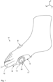
- Figure 1 shows an embodiment of a foot orthosis 10 for correcting foot deformities. More precisely, the Figure 1 The foot orthosis shown is intended to treat the pathological misalignment of a big toe 12, also known as valgus position of the big toe, and a metatarsophalangeal joint 14, also known as varus position of the metatarsophalangeal joint, known as hallux valgus.
- the foot orthosis 10 shown here can also be used to prevent hallux valgus.
- big toe is abbreviated to the term “toe” below and the term “metatarsal joint” is abbreviated to "metatarsal joint”.
- the foot orthosis 10 is intended to be attached to a foot to be treated in the manner of a clamp, in particular a tension clamp, and to be fixed in a predetermined position.
- the foot orthosis 10 is designed and configured to have a therapeutic effect on the foot when attached to the foot by introducing targeted corrective forces into the foot, in particular in the area of the toe 12 and the metatarsophalangeal joint 14, as will be described in more detail below.
- the foot orthosis 10 shown is intended for use on the patient's right foot.
- a foot orthosis 10 shown in Figure 1 A mirror-symmetrical foot orthosis can be used in the configuration shown.
- the foot orthosis 10 comprises a toe segment 16 that can be fastened to the toe 12 and a ball segment 18 that is arranged in the area of the metatarsophalangeal joint 14 and can be fastened thereto, which are coupled so that they can pivot relative to one another by means of a joint unit 20.
- the foot orthosis 10 also comprises a metatarsal segment 22 that can be fastened to or in the area of the metatarsal, which is connected to the ball segment 18 in a force and moment-transmitting manner.
- the foot orthosis 10 is designed to exert a first corrective force F1 on the toe 12 via the toe segment 16, to exert a second corrective force F2 on the metatarsophalangeal joint 14 via the ball segment 18, which is opposite to the first corrective force F1 and spaced parallel thereto, and to exert a holding force F3, which can form a third corrective force, on the metatarsal region via the metatarsal segment 22, wherein the holding force F3 points in the direction of the first corrective force F1 and is arranged parallel thereto at a spaced parallel distance therefrom.
- the individual segments 16, 18, 22 of the foot orthosis 10 are elastically deformable, wherein the different forces F1, F2, F3 acting on the foot by the foot orthosis 10 are provided in the form of tension and/or bending forces induced by elastic deformation of the foot orthosis 10.
- This design can ensure that the forces F1, F2, F3 exerted by the foot orthosis 10 continue to act on the foot even when the foot is moved and the shape of the foot changes during use.
- the first corrective force F1, the second corrective force F2 and the holding force F3 are arranged parallel or substantially parallel to one another and spaced apart from one another.
- the first corrective force F1 and the holding force F3 point in the medial direction and are parallel or substantially parallel to a transverse axis Y of the foot orthosis 10.
- the second corrective force F2 points in the lateral direction.
- the first corrective force F1, the second corrective force F2 and the holding force F3 are further arranged orthogonal or substantially orthogonal to a longitudinal axis X and a vertical axis Z of the foot orthosis 10.
- the toe segment 16 is designed in the form of a bracket, in particular a tensioning or bending bracket, which, when attached to the foot, encompasses the toe 12.
- the toe segment 16 extends from a medial side of the foot, starting from the ball segment 18, over a toe underside to a lateral side of the toe 12.
- the toe segment 16 extends in sections along the toe underside.
- the toe segment 16 can also extend along a toe top.
- the toe segment 16 extends over a radian measure of essentially one ⁇ radian around a toe longitudinal axis L, so that the toe segment 16 extends from one side of the toe 12 and the metatarsophalangeal joint 14 to the opposite side of the toe 12, as in Figure 1 shown.
- the toe segment 16 is designed with a contact surface 24 intended for the toe 12.
- the contact surface 24 is designed in the form of a turning surface, the orientation of which, i.e. the surface normal of which changes along the toe's longitudinal axis L and preferably points towards the toe's longitudinal axis. In this way, the contact surface 24 and thus also the toe segment 16 extend along a helical line around the toe 12.
- the toe segment 16 is designed, in the state attached to the foot, to transmit shear forces and/or bending forces in the direction of the first corrective force F1 between the joint unit 20 and the toe 12 to be treated in order to thus contribute to the generation of the first corrective force F1.
- the toe segment 16 In order to exert the first corrective force F1 on the toe 12, the toe segment 16 comprises a toe support section 26 which, in the fastened state of the foot orthosis 10, rests against a lateral side of the toe 12, i.e. against a side of the toe 12 pointing in the lateral direction.
- the toe support section 26 is formed by a distal end section of the toe segment 16.
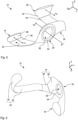
- the toe segment 16 further comprises a toe base section 28 which is integrally and materially connected to the toe support section 26 and adjoins it, as indicated by a dotted line in Figure 2 indicated.
- the toe segment 16, in particular the toe support section 26, is provided in the form of a bending spring.
- the first correction force F1 is thus provided in the form of a tensioning force or bending force induced by an elastic deformation of the toe segment 16.
- the toe segment is designed such that, in the state fastened to the foot, the toe segment 16 is arranged in a tensioning position in which the toe segment 16 is in a position decoupled from the foot. state of the foot orthosis 10, is elastically deflected in a direction opposite to the first corrective force F1.
- Fig. 4 the foot orthosis 10 is shown in a state decoupled from the foot and therefore exposed, in which the toe segment 16 is arranged in its rest position. Furthermore, a state of the toe segment 16 is indicated by means of a dashed line 30 in which it is arranged in the tensioned position, ie in the state fastened to the foot. An end section of the toe support section 26 in the tensioned position is deflected by at least 0.3 cm or 0.5 cm, for example by at least 1.0 cm, compared to the rest position and is translationally displaced along the direction opposite to the first correction force F1.
- the ball segment 18 When the foot orthosis is attached to the foot, the ball segment 18 is arranged in the area of the metatarsophalangeal joint 14 and rests against the foot in the area of the metatarsophalangeal joint 14.
- the ball segment 18 is intended to be engaged with the foot in the area of the metatarsophalangeal joint 14 in order to provide a force-transmitting coupling between the foot in the area of the metatarsophalangeal joint 14 and the ball segment 18 when the foot orthosis 10 is attached to the foot.
- the ball segment 18 rests in the area of a lateral, ball-shaped bulge of the foot, which is referred to as a pseudoexostosis.
- the ball segment 18 comprises a through-opening 32 that extends along a pivot axis S of the joint unit 20.
- An edge 34, in particular a rounded edge 34, of the ball segment 18 which radially delimits the through-opening 32 rests against the ball-shaped bulge on the foot all the way around.
- a part of the metatarsophalangeal joint 14, in particular the ball-shaped bulge is received and arranged in the through-opening 32.
- the through-opening 32 on the ball segment 18 can have a diameter, in particular a minimum diameter, of at least 2 cm or 2.5 cm in cross section.
- the ball segment 18 comprises a ball support section 36 which, in the fastened state of the foot orthosis 10, rests against the ball of the metatarsophalangeal joint, in particular medially and plantarly against the ball of the metatarsophalangeal joint.
- the ball segment 18 can further comprise a ball base section 38 which forms the part of the ball segment 18 which extends along the sole of the foot.
- the ball base section 38 is integrally and materially connected to the ball support section 36 and adjoins it, as shown by a dotted line in Figure 3 indicated.
- the ball segment 18, in particular the ball support section 36, is provided in the form of a bending spring.
- the second correction force F2 is thus provided in the form of a tensioning force or bending force induced by an elastic deformation of the ball segment 18.
- the ball segment 18 is designed such that, when attached to the foot, the ball segment 18 is arranged in a tensioning position in which the ball segment is elastically deflected in a direction opposite to the second correction force F2 compared to a rest position in which the ball segment is arranged in a state of the foot orthosis 10 decoupled from the foot.
- An end section of the ball support section 36 in the tensioning position can be deflected by at least 0.3 cm or 0.5 cm compared to the rest position and can be translationally displaced along the direction opposite to the second correction force F2.
- the relative deflection of the ball segment 18 can be less than that of the toe segment 16.
- the ball segment 18 is connected to the metatarsal segment 22 in a force and moment-transmitting manner.
- the metatarsal segment 22 can be fastened to the metatarsal of the foot to be treated and is arranged partially opposite the ball segment 18, in particular the ball support segment 36.
- the metatarsal segment 22 is provided in the form of a bracket, in particular a tensioning bracket, which partially encompasses a lateral metatarsal region, in particular a lateral metatarsal region, when the foot orthosis 10 is fastened to the foot.
- the metatarsal segment 22 designed as a bracket can be designed to absorb shear forces and/or bending forces, in particular in the direction of the holding force, when fastened to the foot, and to transmit them between the ball segment 18 and the metatarsal to be treated.
- the midfoot segment 22 comprises a midfoot support section 40, which rests laterally on the midfoot in the fastened state of the foot orthosis 10.
- the midfoot support section 40 can be formed by an end section of the midfoot segment 22.
- the midfoot segment 22 further comprises a midfoot base section 42.
- the midfoot base section 42 is integrally and materially connected to the midfoot support section 40 and adjoins it, as shown by a dotted line in Figure 2 indicated.
- the holding force F3 is thus provided in the form of a tensioning force or bending force induced by an elastic deformation of the metatarsal segment 22.
- the metatarsal segment 22 is designed such that, in the state fastened to the foot, the metatarsal segment 22 is arranged in a tensioning position in which the metatarsal segment 22 is in relation to a resting position of the metatarsal segment 22 in which the metatarsal segment 22 is arranged in a state of the foot orthosis 10 decoupled from the foot, is elastically deflected in a direction opposite to the holding force F3.
- Fig. 4 illustrated by means of a further dashed line 44, which indicates a state of the metatarsal segment 22 in which it is arranged in the clamping position, ie in the state fastened to the foot.
- An end section of the metatarsal support section 40 in the clamping position is deflected by at least 0.5 cm or 1.0 cm, for example by 2 cm, compared to the rest position and is translationally displaced along the direction opposite to the holding force F3.
- the metatarsal segment 22 and/or the toe segment 16 can optionally be provided with bandages.
- the toe segment 16 can fix the toe 12 clamped in the toe segment 16 in a form-fitting and/or force-fitting manner relative to the toe segment 16 by means of a bandage or a support band.
- the bandage or the support band can rest against the toe 12 in the circumferential direction at least in sections and be connected to the toe segment 16.
- the metatarsal segment 22 can be provided with a second bandage or a second support band, which is guided around the metatarsal in the circumferential direction and is connected at its ends to the metatarsal segment 22 in order to fix the metatarsal in the metatarsal segment 22 in a form-fitting and/or force-fitting manner.
- the toe segment 16 and/or the ball segment 18 and/or the metatarsal segment 22 are designed with thin walls.
- the toe segment 16 and/or the ball segment 18 and/or the metatarsal segment 22 can be constructed or consist of plate-shaped and/or shell-shaped elements that have a maximum wall thickness of less than 3 mm or 2 mm or 1 mm.
- the toe segment 16, the ball segment 18 and the metatarsal segment 22 are preferably made of plastic.
- plastics that can be plastically deformed under high force, i.e. higher than the correction forces F1, F2 and the holding force F3, or under the influence of heat are suitable for this purpose.
- the foot orthosis can be adapted to the geometric design of a foot to be treated with reduced effort.
- the correction and holding forces F1, F2, F3 caused by elastic deformation can also be adapted in this way.
- At least one of the support sections 26, 36, 40 can have a lower rigidity, in particular with respect to shear and/or bending forces in the direction of the first or second correction force F1, F2, than the base section 28, 38, 42 adjacent thereto.
- the at least one support section 26, 36, 40 can be made of a material that has a lower modulus of elasticity or a lower hardness, for example a lower Shore hardness, compared to the material of the adjacent base element 28, 38, 42.
- the toe segment 16 and the ball segment 18 are coupled by means of the joint unit 20 so that they can pivot relative to one another about the pivot axis S.
- the pivot axis S of the joint unit 20 is arranged in alignment or essentially in alignment with the flexion-extension joint axis of the metatarsophalangeal joint 14.
- the flexion-extension joint axis is understood to be the joint axis about which the toe 12 is pivoted relative to the metatarsal during flexion and extension movements.
- the joint unit 20 is arranged on the medial side of the foot when attached to the foot.
- the joint unit 20 is provided in the form of a rotary joint, in particular in the form of a hubless ring joint, which is arranged around the through opening 32.
- the joint unit 20 is provided with the through opening 32 or alternatively with a recess in order to partially accommodate the medially bulging part of the metatarsophalangeal joint 14, in particular the pseudoexostosis, in the state attached to the foot, as already described above in connection with the through opening 32.
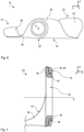
- Figure 7 shows a longitudinal section along the pivot axis S through the joint unit 20.
- the joint unit 20 is formed from at least two components, but is not limited thereto and can be formed from more than two components in alternative embodiments.
- the joint unit 20 comprises a first joint element 46 coupled to the toe segment 16, in particular integrally or materially connected thereto, and a second joint element 48 which is designed to be complementary thereto and which is in engagement and which is coupled to the ball segment 18, in particular integrally or materially connected thereto.
- first joint element 46 is formed by an end section of the toe base section 28 and the second joint element 48 is formed by an end section of the ball support section 36.
- the second joint element 48 is provided with a receiving groove 50 which runs around the pivot axis S and which is in engagement with a connecting ring 52 of the first joint element 46 which is designed to be complementary thereto.
- the receiving groove 50 extends in the radial direction to the pivot axis S such that the receiving groove 50 is limited in both directions along the pivot axis S and has an opening in the radially outward direction through which the connecting ring 52 projects into the receiving groove 50.
- the receiving groove 50 in the longitudinal section along the pivot axis S has a substantially U-shaped contact or sliding surface for the connecting ring 52.
- the receiving groove 50 and the connecting ring 52 are thus positively engaged in both directions along the pivot axis S. In this way, an unintentional loosening of the connection between the first and the second joint element 46, 48 can be effectively counteracted and at the same time a simple and robust construction of the joint unit 20 can be ensured.
- the joint unit 20 is designed such that, when the foot orthosis 10 is attached to the foot, the second joint element 48 is arranged between the foot and the first joint element 46, wherein a connecting web 54 of the second joint element 48, which forms the receiving groove 50, circumferentially delimits the through opening 32 in the radial direction.
- the connecting web 54 extends along the pivot axis S such that the connecting web 54 is arranged in the axial direction of the joint unit 20, i.e. along the pivot axis S, overlapping the first joint element 46 and enclosing the connecting ring 52.
- the ball base portion 38 and the metatarsal base portion 42 are coupled such that they are translationally displaceable relative to each other along an axis which lies in a plane with the longitudinal axis X and a transverse axis Y of the foot orthosis 10, but runs transversely to them, as in Figure 8 indicated by the arrow A.
- the two sections 38, 42 are translationally displaceable relative to one another along the longitudinal axis X and the transverse axis Y of the foot orthosis 10.
- the foot orthosis 10 is designed in such a way that the two sections 38, 42 can be fixed in a desired position relative to one another in a force-fitting and/or form-fitting manner.
- the foot orthosis 10 may further comprise a foot cushion 56 that can be releasably connected to the ball base portion 38 and/or the metatarsal base portion 42 and is displaceable relative thereto in order to arrange the foot cushion 56 in a patient-specific manner, as in Figure 9 indicated by arrow B.
- a foot cushion 56 that can be releasably connected to the ball base portion 38 and/or the metatarsal base portion 42 and is displaceable relative thereto in order to arrange the foot cushion 56 in a patient-specific manner, as in Figure 9 indicated by arrow B.
- Figure 10 shows a second embodiment of the foot orthosis 20, which differs in particular in the structure and arrangement of the toe segment 16, the ball segment 18 and the joint unit 20 from the one in Figures 1 to 9 shown embodiment.
- the joint unit 20 is arranged along the sole of the foot in the state attached to the foot.
- the joint unit 20 is arranged plantarly, ie on the sole of the foot or in the area of the sole of the foot, on the foot in use.
- the joint unit 20 is provided as a bending joint which is formed by end sections of the plate- or shell-shaped toe base portion 28 and the ball base portion 38.
- the joint unit 20 extends over a length along the transverse axis Y of at least 1 cm.
- the joint unit 20 extends along the transverse axis Y substantially over the entire width of the mutually engaging end portions of the toe base portion 28 and the ball base portion 38.
- the toe base section 28 and the ball base section 38 extend in a plate-like or shell-like manner along a plane that runs parallel to the corrective forces F1, F2.
- the joint unit 20 also lies and extends in this imaginary plane. In this way, the proposed foot orthosis 10, in particular the joint unit 20, is designed to be particularly robust against bending and shearing forces in the direction of the corrective forces F1, F2.
- the joint unit 20 provided as a flexural joint has a lower flexural rigidity with respect to pivoting movements about the pivot axis S than the adjacent areas of the toe segment 16 and the ball segment 18. This can be achieved by making the foot orthosis 10 thinner in the area of the joint unit 20 and/or made of a material that is more flexible than the adjacent areas.
- the foot orthosis can have a composite material in the area of the joint unit 20 that has fibers, in particular rigid fibers, that extend transversely to the pivot axis S or parallel to the foot orthosis' longitudinal axis X.
- the joint unit 20 can be designed as a film hinge.
- the joint unit 20 can also be designed as a rotary joint, in particular as a single-joint hinge.
- the foot orthosis 10 shown here does not require a metatarsal segment.
- the embodiment shown here can be designed to be worn in combination with a stocking or footwear, thereby providing the holding forces that are helpful for the therapeutic treatment and hold the foot orthosis 10 on the foot.
- Figure 11 shows a further embodiment of the foot orthosis 10, in which the toe segment 16 is opposite to the Figure 10 embodiment shown is provided with a medial side portion 58 opposite the toe support portion 26.
- Figure 12 shows a further embodiment of the foot orthosis 10, which, compared to the Figures 10 and 11 shown embodiments is equipped with a metatarsal segment 22.
- the metatarsal segment 22 comprises a metatarsal support section 40, which is provided with coupling elements 60 for a support band not shown here.
- the coupling elements 60 are in the embodiment shown here Embodiment provided as slotted openings through which the support band is guided when wrapped around the metatarsal, in order to fix the foot orthosis 10 to the foot to be treated and to introduce the holding force into the foot via the support band.
- the metatarsal segment 22 is coupled to the ball segment 18 via a further joint unit 62 so as to be pivotable about a further pivot axis S2, which is formed parallel to the pivot axis S of the joint unit 20 between the toe segment 16 and the ball segment 18.
- the further joint unit 62 is designed in a manner corresponding to the joint unit 20.
- Figures 13 and 14 show a further embodiment of the foot orthosis 10, in which the metatarsal segment 22 comprises two opposite metatarsal support sections 40, each with a coupling element 60, through which a support band 64 to encompass the metatarsal is guided.
Landscapes
- Health & Medical Sciences (AREA)
- Nursing (AREA)
- Orthopedic Medicine & Surgery (AREA)
- Engineering & Computer Science (AREA)
- Biomedical Technology (AREA)
- Heart & Thoracic Surgery (AREA)
- Vascular Medicine (AREA)
- Life Sciences & Earth Sciences (AREA)
- Animal Behavior & Ethology (AREA)
- General Health & Medical Sciences (AREA)
- Public Health (AREA)
- Veterinary Medicine (AREA)
- Orthopedics, Nursing, And Contraception (AREA)
Description
- Die vorliegende Erfindung betrifft eine Fußorthese zur Korrektur von Fehlstellungen, insbesondere zur Behandlung von Hallux valgus.
- Pathologische Fehlstellungen im Mittelfuß- und Vorfußbereich eines Patienten können unterschiedliche Ursachen haben, wie beispielsweise genetische Veranlagung, das Tragen von falschem Schuhwerk, insbesondere von zu engen oder hochhackigen Schuhen, oder eine Abflachung des Längs- und Quergewölbes infolge einer Instabilität des Bindegewebes im Mittelfußbereich. Insbesondere die als Hallux valgus bezeichnete Fehlstellung der Großzehe im Großzehengrundgelenk, auch als Valgusstellung bezeichnet, kommt hierbei aufgrund der stetig wachsenden Fallzahlen mehr Bedeutung zu.
- Hallux valgus entsteht, indem die Großzehe im Großzehengrundgelenk durch Muskelzug in die fußinnenseitige Richtung gezogen wird. Dabei tritt der erste Mittelfußknochen als ballenförmige Ausbuchtung am Zehengrundgelenk fußinnenseitig hervor, was als Pseudoexostose bezeichnet wird. Zudem geht mit dem Hallux valgus häufig eine Änderung der Länge und der Zugrichtung der Sehnen einher, wodurch sich die Fehlstellung im Laufe der Zeit weiter verstärken kann. Dabei entwickelt sich eine Arthrose des Großzehengrundgelenks, die im fortgeschrittenen Stadium chirurgisch behandelt werden muss.
- Um den Krankheitsprozess aufzuhalten oder diesem entgegenzuwirken, sind neben chirurgischen Eingriffen auch die Anwendung konservativer Therapiemethoden bekannt. Beispielsweise ist die Verwendung von Tapeverbänden oder Orthesen bekannt zur Behandlung des Fußes in einer Ruhestellung. Aufgrund der verlangten Ruhestellung des Fußes während der Therapie werden diese vorwiegend nachts eingesetzt.
- Weiterhin sind Orthesen bekannt, die in einem am Fuß befestigten Zustand einer geschienten Großzehe einen Bewegungsfreiheitsgrad entlang der Flexion-Extension-Bewegungsrichtung einräumen.
DE 102 40 121 B4 offenbart beispielsweise eine orthopädische Vorrichtung in Form einer Gelenkbiegeschiene, die um eine Flexions-Extensions-Bewegungsachse der zu korrigierenden Zehe gelenkig ausgebildet ist. Hierzu ist die Gelenkbiegeschiene mit einer an der Fußinnenseite anliegenden Gelenkeinrichtung versehen, von der sich zwei Biegeschenkel entlang der Fußinnenseite erstrecken. Um die Gelenkbiegeschiene am Fuß zu befestigen, ist ein erster Biegeschenkel über eine erste Bandage an der Zehe und ein zweiter Biegeschenkel über eine zweite Bandage am Mittelfuß befestigt. -
US 2,958,324 A offenbart eine Vorrichtung zur Behandlung von Zehenfehlstellungen. Die Vorrichtung umfasst einen U-förmigen Ballenabschnitt, dessen ober- und unterseitig am Fuß anliegende Schenkel mit einem Zehenbügel gelenkig verbunden sind. Weiterer Stand der Technik ist aus derDE 85 29 083 U1 ,US 1,183,062 A ,US 2014/0350447 A1 undUS 2012/310131 A1 bekannt. - Ausgehend von dem bekannten Stand der Technik ist es eine Aufgabe der vorliegenden Erfindung, eine verbesserte Fußorthese zur Korrektur von Fehlstellungen, insbesondere zur Behandlung von Hallux valgus, bereitzustellen, die insbesondere eine effektive therapeutische Behandlung sicherstellt und gleichzeitig aufwandsreduziert herstellbar und kompakt ausgestaltet ist.
- Die Aufgabe wird durch eine Fußorthese mit den Merkmalen des unabhängigen Anspruchs gelöst. Vorteilhafte Weiterbildungen ergeben sich aus den Unteransprüchen sowie der vorliegenden Beschreibung und den Figuren.
- Entsprechend wird eine Fußorthese zur Korrektur von Fehlstellungen eines Fußes, insbesondere zur Behandlung oder Vorbeugung von Hallux valgus, bereitgestellt. Die Fußorthese umfasst ein an einer Zehe des zu behandelnden Fußes befestigbares Zehensegment und ein im Bereich eines Zehengrundgelenks des zu behandelnden Fußes anzuordnendes Ballensegment, die mittels einer Gelenkeinheit relativ zueinander verschwenkbar gekoppelt sind. Die Fußorthese ist dazu eingerichtet und derart ausgebildet, in einem am Fuß ordnungsgemäß befestigten Zustand über das Zehensegment eine erste Korrekturkraft auf die Zehe auszuüben und über das Ballensegment eine zu der ersten Korrekturkraft entgegengesetzte zweite Korrekturkraft auf das Zehengrundgelenk auszuüben. Die Gelenkeinheit ist derart ausgebildet, dass das Zehensegment und das Ballensegment relativ zueinander um eine Schwenkachse verschwenkbar sind, die im Wesentlichen parallel zu einer Flexion-Extension-Gelenkachse des Zehengrundgelenks ist. Das Zehensegment ist in Form eines Bügels ausgebildet, der in dem am Fuß befestigten Zustand die Zehe zumindest teilweise umgreift. Das Zehensegment umfasst einen Zehenstützabschnitt, der in dem am Fuß befestigten Zustand der Fußorthese an einer lateralen Seite der Zehe anliegt.
- Zur Interaktion mit der Zehe des zu behandelnden Fußes, d.h. zum Ausüben der ersten Korrekturkraft auf die Zehe, ist die Fußorthese mit dem als Bügel ausgebildeten und die Zehe umgreifenden Zehensegment ausgestattet. Im Rahmen der vorliegenden Erfindung wurde erkannt, dass indem das Zehensegment als ein die Zehe zumindest teilweise umgreifender Bügel ausgestaltet ist, eine für die vorgesehene Anwendung der Fußorthese kraftfluss- und belastungsoptimierte strukturelle Ausgestaltung bereitgestellt werden kann. Denn indem das bügelartige Zehensegment die Zehe zumindest teilweise umgreift, wird ermöglicht, dass durch die sich so ergebende Geometrie des Zehensegments die Steifigkeit des Bauteils, insbesondere dessen Flächenträgheitsmoment, im Hinblick auf die in dem Zehensegment übertragenen, die erste Korrekturkraft induzierenden Biegekräfte zumindest abschnittsweise erhöht wird. Auf diese Weise kann das Zehensegment zumindest abschnittsweise schmaler und/oder dünner ausgestaltet sein und entsprechend zu einer kompakten Bauweise der Fußorthese beitragen. Das Tragen der Fußorthese in üblichem Schuhwerk kann so für den Patienten gegenüber bekannten Vorrichtungen, bei denen sich Biegeschenkel entlang der Zehe an der Fußinnenseite erstrecken, deutlich angenehmer sein. Diese Ausgestaltung der vorgeschlagenen Lösung ermöglicht weiterhin, dass auf Bandagen zum Befestigen der Fußorthese an dem Fuß verzichtet werden kann. Entsprechend kann die vorgeschlagene Fußorthese weniger unterschiedliche Komponenten umfassen und daher kostengünstiger in der Herstellung sein.
- Die vorgeschlagene Fußorthese ist dafür vorgesehen, eine pathologische Fehlstellung eines Fußes, insbesondere einer Zehe und/oder eines Zehengrundgelenks, zu behandeln, entgegenzuwirken und/oder vorzubeugen. Insbesondere kann die Fußorthese zur Vorbeugung oder Behandlung von Hallux valgus eingesetzt werden, ist aber nicht auf diese Anwendung beschränkt. Entsprechend ist die Fußorthese dafür vorgesehen, an einem Fuß eines Patienten befestigt zu werden und in dem am Fuß befestigten Zustand auf den Fuß, insbesondere auf die Zehe und/oder das Zehengrundgelenk, therapeutisch einzuwirken.
- In der vorliegenden Offenbarung bezieht sich der Ausdruck "in einem/dem am Fuß ordnungsgemäß befestigten Zustand", vorliegend auch mit "in dem befestigten Zustand" abgekürzt, auf einen Zustand, in dem die Fußorthese an einem Fuß eines Patienten bestimmungsgemäß befestigt ist und entsprechend einen gewünschten therapeutischen Effekt zur Korrektur oder zur Vorbeugung von Fehlstellungen bewirkt. Die Fußorthese kann fußspezifisch für einen linken oder rechten Fuß eines Patienten ausgestaltet sein. Mit anderen Worten kann die Fußorthese entweder zur Verwendung an dem linken oder dem rechten Fuß des Patienten vorgesehen und ausgebildet sein. Eine für den linken Fuß vorgesehene Fußorthese kann spiegelsymmetrisch zu einer für den rechten Fuß eines Patienten vorgesehenen Fußorthese ausgebildet sein.
- Die vorgeschlagene Fußorthese ist derart ausgestaltet, dass sie in dem befestigten Zustand Korrekturkräfte auf den Fuß ausübt. Unter dem Begriff "Korrekturkräfte" werden vorliegend solche Kräfte verstanden, die eine therapeutische Wirkung auf den zu behandelnden Fuß haben. Insbesondere bewirken die Korrekturkräfte, dass die von der Fehlstellung betroffenen Teile des Fußes in eine anatomisch korrekte oder beabsichtigte Position gelenkt werden, um einen gewünschten therapeutischen Effekt zu erzielen.
- Die vorgeschlagene Fußorthese ist dazu eingerichtet, in dem am Fuß des Patienten befestigten Zustand wenigstens die erste und zweite Korrekturkraft mittels des Zehensegments und des Ballensegments auf den zu behandelnden Fuß auszuüben, insbesondere unmittelbar auszuüben. Durch diese Ausgestaltung unterscheidet sich die vorliegende Fußorthese wesentlich von bekannten Vorrichtungen, die ein Zehengrundgelenk und den diesem zugeordneten Zehenballen oder eine durch die Fehlstellung bewirkte pathologische Pseudoexostose vor äußerer Krafteinwirkung, insbesondere von durch die Vorrichtung auf den Fuß wirkenden Kräften, gewollt oder ungewollt abschirmen. Im Rahmen der vorliegenden Erfindung wurde erkannt, dass eine besonders effektive therapeutische Wirkung erzielt werden kann, indem die Fußorthese neben der auf die Zehe wirkenden ersten Korrekturkraft zusätzlich die auf das Zehengrundgelenk mittels des Ballensegments wirkende zweite Korrekturkraft ausübt. Das dadurch resultierende Zusammenspiel von auf den Fuß ausgeübten Korrekturkräften kann besonders vorteilhaft bei der Behandlung von Hallux valgus sein. Denn durch die vorgeschlagene Ausgestaltung der Fußorthese kann gleichzeitig eine therapeutische Wirkung auf die Valgusstellung der Zehe als auch auf die Varusstellung des Zehengrundgelenks erzielt werden. Somit können Symptomatik und Ursache der Fußfehlstellung gleichzeitig behandelt werden. Die auf den Fuß wirkenden Korrekturkräfte und damit einhergehenden therapeutischen Effekte werden nachstehend im Zusammenhang mit den damit in Verbindung stehenden Komponenten der Fußorthese genauer beschrieben.
- Im Zusammenhang mit dem Zehensegment wird nachfolgend zur Vereinfachung allgemein auf eine Zehe des Fußes Bezug genommen. Hierbei handelt es sich insbesondere um die Großzehe des zu behandelnden Fußes. Die Fußorthese ist hierauf aber nicht beschränkt, sodass mit dem Ausdruck beispielsweise auch die Kleinzehe gemeint sein kann. Im Zusammenhang mit dem Ballensegment wird entsprechend zur Vereinfachung allgemein auf ein Zehengrundgelenk Bezug genommen, wobei insbesondere das Großzehengrundgelenk gemeint ist, die Fußorthese hierauf aber nicht beschränkt ist. Alternativ kann es sich beispielsweise auch um das Kleinzehengrundgelenk handeln.
- In der vorliegenden Offenbarung wird zur Beschreibung der Fußorthese, insbesondere in Bezug auf den zu behandelnden Fuß, ein Bezugssystem verwendet, das auf die Mittellinie des Körpers eines Patienten ausgerichtet ist, wie in der Anatomie üblich. So können die Position und Richtung der einzelnen Komponenten der vorgeschlagenen Fußorthese in dem befestigten Zustand in Bezug auf den in der Fußorthese aufgenommenen Fuß angegeben werden. Dementsprechend bezieht sich der Begriff "medial" auf eine Richtung oder Seite der Fußorthese, die in Richtung einer medialen Ebene des Körpers des Trägers zeigt. In der Anatomie bezieht sich der Begriff "mediale Ebene", die auch als "Mittelsagittalebene" bezeichnet wird, im Allgemeinen auf eine anatomische Ebene, die den Körper in zwei symmetrische Teile teilt. Dementsprechend bedeutet der Begriff "in medialer Richtung" bei der Beschreibung einer Fußorthese eine Richtung, die von dem zu behandelnden Fuß des Patienten in Richtung seines anderen Fußes zeigt. In diesem Sinne bezieht sich der Begriff "lateral" auf eine Richtung oder Seite der Fußorthese, die von der medialen Ebene des Körpers des Trägers weg weist. Dementsprechend bedeutet der Begriff "in lateraler Richtung" bei der Beschreibung einer Fußorthese, welche an einem Fuß des Trägers befestigt ist, in einer Richtung, die von dem anderen Fuß des Trägers weg weist.
- Die Fußorthese umfasst das Zehensegment, das an der Zehe des zu behandelnden Fußes befestigbar ist. Mit anderen Worten ist das Zehensegment dafür vorgesehen, an der Zehe des Fußes an einer vergebenen Position in Eingriff gebracht zu werden, um in dem am Fuß befestigten Zustand der Fußorthese eine kraftübertragende Kopplung zwischen der Zehe und dem Zehensegment bereitzustellen. Entsprechend wird das Zehensegment in dem am Fuß befestigten Zustand der Fußorthese in einer gewünschten Position an dem Fuß gehalten und insbesondere kraftschlüssig und/oder formschlüssig an der Zehe befestigt.
- Das Zehensegment ist dafür vorgesehen, in dem am Fuß befestigten Zustand die erste Korrekturkraft auf die Zehe auszuüben. Die erste Korrekturkraft kann auf die Zehe in medialer Richtung wirken.
- Wie vorangehend beschrieben, ist das Zehensegment in Form eines Bügels ausgebildet. Unter dem Begriff "Bügel" wird vorliegend und im Allgemeinen eine Komponente verstanden, die dazu eingerichtet und dafür vorgesehen ist, unterschiedliche Belastungen aufzunehmen und zu übertragen, wie zum Beispiel Längskräfte, Querkräfte, Scherkräfte, Biegekräfte, Biegemomente, Torsionsmomente, etc. So ist ein Bügel dafür vorgesehen, neben Zugkräften auch Druckkräfte entlang seiner Längsachse und Querkräfte quer zu seiner Erstreckungsachse, insbesondere seiner Längsachse, aufzunehmen und zu übertragen. Diese Eigenschaft unterscheidet einen Bügel wesentlich von einer Bandage, die zwar zur Übertragung von Zugkräften, aber nicht zur Übertragung von Druck- und/oder Querkräften vorgesehen ist.
- Entsprechend kann das als Bügel ausgebildete Zehensegment dazu eingerichtet sein, in dem am Fuß befestigten Zustand Scherkräfte und/oder Biegekräfte, insbesondere in Richtung der ersten Korrekturkraft, aufzunehmen und zu übertragen, insbesondere zwischen der Gelenkeinheit und der zu behandelnden Zehe, um die erste Korrekturkraft auf die Zehe auszuüben.
- Das als Bügel ausgebildete Zehensegment ist derart ausgestaltet, dass es in dem am Fuß befestigten Zustand die Zehe zumindest teilweise umgreift. Unter einem Umgreifen der Zehe wird vorliegend verstanden, dass das Zehensegment sich in dem am Fuß befestigten Zustand in Zehenumfangsrichtung entlang der Zehe erstreckt. Vorzugsweise erstreckt sich das Zehensegment um die Zehe über ein Bogenmaß von wenigstens 1/2 π rad um die Zehenlängsachse. Das bedeutet, dass sich das Zehensegment in Umfangsrichtung wenigstens entlang eines Viertels des Umfangs einer Zehe erstreckt. Das Zehensegment kann sich beispielsweise über ein Bogenmaß von im Wesentlichen einem π rad um die Zehenlängsachse erstrecken, sodass sich das Zehensegment von einer Seite der Zehe oder des Zehengrundgelenks zu der entgegengesetzten Seite der Zehe erstreckt.
- Im Hinblick auf die geometrische Ausgestaltung ist das als Bügel ausgebildete Zehensegment vorzugsweise platten- und/oder schalenförmig ausgebildet. Beispielsweise kann das Zehensegment in seiner geometrischen Ausgestaltung riemen- oder bandförmig ausgebildet sein und insbesondere biegesteif sein. Entsprechend kann das Zehensegment mit einer für die Zehe vorgesehenen Kontaktfläche und einer gegenüberliegenden Auflagefläche ausgestaltet sein. In dem am Fuß befestigten Zustand der Fußorthese kann die Kontaktfläche des Zehensegments an der Zehe anliegen, insbesondere unmittelbar anliegen. Die Kontaktfläche kann hierbei in Form einer Wendefläche ausgestaltet sein, deren Orientierung, d.h. deren Flächennormale, sich entlang der Zehenlängsachse ändert und vorzugsweise auf die Zehenlängsachse zeigt. Auf diese Weise kann sich die Kontaktfläche und damit auch das Zehensegment entlang einer Schraubenlinie um die Zehenlängsachse erstrecken.
- Um die erste Korrekturkraft in die Zehe einzuleiten oder auf diese auszuüben, umfasst das Zehensegment einen Zehenstützabschnitt, der in dem befestigten Zustand der Fußorthese anliegt an der lateralen Seite der Zehe, d.h. an der in lateraler Richtung zeigenden Seite. Mit anderen Worten kann der Zehenstützabschnitt dazu eingerichtet sein, die erste Korrekturkraft in die Zehe einzuleiten oder auf die Zehe auszuüben, wobei die erste Korrekturkraft in die mediale Richtung zeigt oder mit dieser zusammenfällt, insbesondere im Wesentlichen zusammenfällt. Der Zehenstützabschnitt kann durch einen Endabschnitt des Zehensegments gebildet sein, der insbesondere distal angeordnet sein kann.
- Das Zehensegment kann ferner einen Zehenbasisabschnitt umfassen, der denjenigen Teil des Zehensegments bilden kann, der sich entlang der Zehenoberseite oder entlang der Zehenunterseite der zu behandelnden Zehe erstreckt. Mit anderen Worten kann der Zehenbasisabschnitt plantar und/oder dorsal angeordnet sein. Entsprechend kann in dem befestigten Zustand der Fußorthese der Zehenbasisabschnitt parallel oder im Wesentlichen parallel zu der natürlichen Auflagefläche des Fußes verlaufen. Gemäß einer Ausgestaltungsform kann in dem am Fuß befestigten Zustand die Zehe zumindest abschnittsweise auf dem Zehenbasisabschnitt aufliegen. Alternativ kann der Zehenbasisabschnitt zumindest abschnittsweise auf der Zehe aufliegen. Der Zehenbasisabschnitt ist vorzugsweise kraft- und/oder momentübertragend mit dem Zehenstützabschnitt verbunden, beispielsweise integral oder stoffschlüssig verbunden.
- Der Zehenstützabschnitt kann in Form eines Schenkels ausgebildet sein oder einen Schenkel umfassen und insbesondere eine Biegefeder bilden. Insbesondere kann der Zehenstützabschnitt dünnwandig ausgebildet sein. Weiterhin kann der Zehenstützabschnitt senkrecht oder im Wesentlichen senkrecht zu dem Zehenbasisabschnitt angeordnet sein. Alternativ oder zusätzlich kann der Zehenstützabschnitt vertikal oder im Wesentlichen vertikal angeordnet sein.
- Der Zehenstützabschnitt kann relativ zu der Zehe lateral angeordnet sein. Entsprechend kann der Zehenstützabschnitt unmittelbar auf die Zehe die erste Korrekturkraft ausüben, indem dieser auf die Zehe in medialer Richtung drückt. Alternativ kann der Zehenstützabschnitt ein Stützband umfassen oder bilden, insbesondere in Form eines Riemens, einer Schlaufe, eines Bandes, eines Gurtes, etc. Das Stützband kann an einer lateralen Seite der Zehe anliegen und auf diese die erste Korrekturkraft ausüben, wobei das Stützband an dessen Endabschnitten endsprechend mit einer Zugkraft beaufschlagt sein kann. Hierzu kann das Stützband an einem relativ zu der Zehe medial angeordneten Schenkel des Zehenstützabschnitts befestigt sein und/oder kraftübertragend mit dem Zehenbasisabschnitt verbunden sein. In dem befestigten Zustand der Fußorthese kann das Stützband zumindest teilweise um die Zehe angeordnet sein. Mit anderen Worten kann in dem befestigten Zustand die Zehe in dem Stützband derart angeordnet sein, dass das Stützband zumindest teilweise in Umfangrichtung an der Zehe anliegt. Das Stützband kann zugstarr oder elastisch ausgebildet sein, insbesondere entlang dessen Umfangsrichtung.
- Das Zehensegment, insbesondere der Zehenbasisabschnitt und/oder der Zehenstützabschnitt, kann/können dünnwandig ausgebildet sein, um so zu einer kompakten Bauweise der Fußorthese beizutragen. Insbesondere kann/können das Zehensegment, insbesondere der Zehenbasisabschnitt und/oder der Zehenstützabschnitt, eine maximale Wanddicke von weniger als 3 mm oder weniger als 2 mm oder weniger als 1 mm aufweisen. Mit anderen Worten kann das Zehensegment, insbesondere der Zehenbasisabschnitt und/oder der Zehenstützabschnitt, aus wenigstens einem plattenförmigen Bauteil aufgebaut sein. Weiterhin kann/können das Zehensegment, insbesondere der Zehenbasisabschnitt und/oder der Zehenstützabschnitt, schalenförmig oder kalottenförmig ausgebildet sein und insbesondere in dessen Form an die Form der zu behandelnden Zehe angepasst sein. Auf diese Weise kann eine möglichst große Auflagefläche für die Zehe bereitgestellt sein, um das Tragen der Fußorthese für einen Patienten angenehmer zu gestalten. Weiterhin kann so eine kompakte Bauweise der Fußorthese sichergestellt werden.
- Gemäß einer Weiterentwicklung kann das Zehensegment in Form eines Spannbügels ausgebildet sein. In dieser Ausgestaltung kann die erste Korrekturkraft in Form einer durch elastische Verformung des Zehensegments induzierten Spannkraft bereitgestellt sein.
- Die Fußorthese kann derart ausgestaltet sein, dass in einem vom Fuß entkoppelten Zustand der Fußorthese, d.h. in einem Zustand, in dem die Fußorthese in keinem Eingriff mit dem zu behandelnden Fuß steht und entsprechend freiliegt, die Fußorthese, insbesondere das Zehensegment, in einer Ruheposition angeordnet ist, in der die Fußorthese, insbesondere das Zehensegment, nicht elastisch verformt ist. In dem am Fuß befestigten Zustand der Fußorthese kann die Fußorthese, insbesondere das Zehensegment, hingegen in einer Spannposition angeordnet sein, in der die Fußorthese, insbesondere das Zehensegment, elastisch verformt ist. Das Zehensegment, insbesondere der Zehenstützabschnitt, kann in der Spannposition gegenüber der Ruheposition in einer der ersten Korrekturkraft entgegengesetzten Richtung elastisch ausgelenkt sein. Beispielsweise kann der Zehenstützabschnitt, insbesondere ein Endabschnitt des Zehenstützabschnitts, in der Spannposition gegenüber der Ruheposition um wenigstens 0,2 cm, beispielsweise um wenigstens 0,3 cm oder wenigstens 0,5 cm oder wenigstens 1,0 cm, ausgelenkt oder translatorisch verschoben sein, insbesondere entlang der zu der ersten Korrekturkraft entgegengesetzten Richtung.
- In der Spannposition kann das Zehensegment durch dessen elastische Verformung gespannt oder vorgespannt sein in Richtung der ersten Korrekturkraft. Die auf das Zehensegment, insbesondere auf den Zehenstützabschnitt, wirkende Spannkraft oder Biegekraft kann der ersten Korrekturkraft entsprechen. Alternativ kann die auf das Zehensegment, insbesondere auf den Zehenstützabschnitt, wirkende Spannkraft oder Biegekraft im Betrag im Wesentlichen der ersten Korrekturkraft entsprechen.
- Die Fußorthese umfasst ferner das Ballensegment, das in dem am Fuß befestigten Zustand der Fußorthese im Bereich des Zehengrundgelenks angeordnet sein kann und insbesondere im Bereich des Zehengrundgelenks an dem Fuß anliegt. Mit anderen Worten ist das Ballensegment dafür vorgesehen, mit dem Fuß im Bereich des Zehengrundgelenks in Eingriff gebracht zu werden, um in dem am Fuß befestigten Zustand der Fußorthese eine kraftübertragende Kopplung zwischen dem Fuß im Bereich des Zehengrundgelenks und dem Ballensegment bereitzustellen. Entsprechend ist das Ballensegment in dem am Fuß befestigten Zustand an dem Fuß befestigt, insbesondere kraftschlüssig und/oder formschlüssig befestigt, und wird so an einer gewünschten Position an dem Fuß gehalten.
- Genauer kann das Ballensegment derart ausgestaltet sein, dass in dem am Fuß befestigten Zustand das Ballensegment seitlich an dem Fuß im Bereich des Grundgelenkfußballens anliegt, insbesondere seitlich an dem Grundgelenkfußballen anliegt. Beispielsweise kann das Ballensegment in dem am Fuß befestigten Zustand an oder im Bereich von einer seitlichen, ballenförmigen Ausbuchtung des Fußes, insbesondere des ersten Mittelfußknochens, was auch als Pseudoexostose bezeichnet wird, anliegen. In einer Weiterentwicklung kann das Ballensegment derart ausgestaltet sein, dass in dem am Fuß befestigten Zustand das Ballensegment im Bereich des Grundgelenkfußballens anliegt, aber nicht an dem Grundgelenkfußballen oder einer Pseudoexostose selbst anliegt. Hierzu kann das Ballensegment mit einer Ausnehmung oder Durchgangsöffnung versehen sein, die in dem am Fuß befestigten Zustand wenigstens einen Teil des Grundgelenkfußballens, insbesondere die ballenförmige Ausbuchtung am Fuß, beispielsweise die Pseudoexostose, aufnimmt. Ein die Ausnehmung oder die Durchgangsöffnung begrenzender Teil des Ballensegments kann hierbei an dem Fuß in einem Bereich anliegen, der an dem Grundgelenkfußballen, insbesondere an der ballenförmigen Ausbuchtung am Fuß, beispielsweise an der Pseudoexostose, angrenzt. Mit anderen Worten kann die Fußorthese derart ausgestaltet sein, dass in dem am Fuß befestigten Zustand ein seitlich ausbuchtender Teil des Grundgelenkfußballens in der Ausnehmung oder der Durchgangsöffnung des Ballensegments aufgenommen ist. Beispielsweise kann das Ballensegment an dem Fuß umlaufend um den Grundgelenkfußballen, insbesondere um die ballenförmige Ausbuchtung am Fuß, beispielsweise um die Pseudoexostose, angeordnet sein. Die Ausnehmung oder Durchgangsöffnung an dem Ballensegment kann hierbei im Querschnitt einen Durchmesser, insbesondere minimalen oder maximalen Durchmesser, von wenigstens im Wesentlichen 1,5 cm oder von wenigstens im Wesentlichen 2,0 cm oder von wenigstens im Wesentlichen 2,5 cm aufweisen. Diese Ausgestaltung ermöglicht, dass die vorgeschlagene Fußorthese mittels des Ballensegments die zweite Korrekturkraft auf das Zehengrundgelenk ausüben kann, ohne hierfür unmittelbar auf schmerzempfindliche Bereiche des Fußes einwirken zu müssen, Kraft auszuüben oder zu berühren.
- Im Zusammenhang mit der vorliegenden Offenbarung betrifft das Merkmal, dass die "zweite Korrekturkraft auf das Zehengrundgelenk ausgeübt wird", solche Korrekturkräfte, die auf das Zehengrundgelenk therapeutisch einwirken. Solche Korrekturkräfte können mittels der Fußorthese unmittelbar in das Zehengrundgelenk eingeleitet werden. Alternativ können solche Korrekturkräfte mittels der Fußorthese mittelbar auf das Zehengrundgelenk einwirken, beispielsweise indem das Ballensegment eine Korrekturkraft auf einen Mittelfußknochen, insbesondere den ersten Mittelfußknochen, ausübt. Die zweite Korrekturkraft hat insbesondere den Zweck, auf die Varusstellung eines Mittelfußknochens, im Speziellen auf die Varusstellung des ersten Mittelfußknochens, therapeutisch einzuwirken.
- Zur Behandlung von Hallux valgus kann die Fußorthese derart bereitgestellt sein, dass das Ballensegment in dem am Fuß befestigten Zustand an dem Zehengrundgelenk an einer medialen Seite des Fußes anliegt. Die zweite Korrekturkraft kann entsprechend auf das Zehengrundgelenk in einer lateralen Richtung wirken.
- Das Ballensegment kann dazu eingerichtet sein, in dem am Fuß befestigten Zustand Scherkräfte und/oder Biegekräfte, insbesondere in Richtung der zweiten Korrekturkraft, aufzunehmen und zu übertragen, insbesondere zwischen der Gelenkeinheit und dem zu behandelnden Zehengrundgelenk, um die zweite Korrekturkraft auf das Zehengrundgelenk auszuüben. Das Ballensegment kann insbesondere in Form eines Bügels bereitgestellt sein oder einen Teil eines Bügels bilden. Gemäß einer Ausgestaltungsform kann das Ballensegment den Grundgelenkfußballen zumindest abschnittsweise umgreifen. Hierzu kann sich das Ballensegment von einer lateralen Seite des Fußes im Bereich des Zehengrundgelenks in Richtung der Fußsohle erstrecken und insbesondere in seiner Form an die Form des Fußgewölbes angepasst sein. Alternativ kann sich das Ballensegment von der lateralen Seite des Fußes in Richtung des Fußrückens erstrecken. Beispielsweise kann sich das Ballensegment um den Grundgelenkfußballen über ein Bogenmaß von wenigstens 1/2 π rad um die Zehenlängsachse erstrecken.
- Im Hinblick auf die geometrische Ausgestaltung ist das Ballensegment vorzugsweise plattenförmig oder schalenförmig ausgebildet. Beispielsweise kann das Ballensegment in seiner geometrischen Ausgestaltung riemen- oder bandförmig ausgebildet sein. Das Ballensegment ist vorzugsweise biegesteif. Entsprechend kann das Ballensegment mit einer für den Fuß vorgesehenen Kontaktfläche und einer gegenüberliegenden Auflagefläche ausgestaltet sein. In dem am Fuß befestigten Zustand der Fußorthese kann die Kontaktfläche des Ballensegments an dem Fuß anliegen, insbesondere unmittelbar anliegen. Die Kontaktfläche kann hierbei in Form einer Wendefläche ausgestaltet sein, deren Orientierung, d.h. deren Flächennormale sich entlang einer zu der Zehenlängsachse im Wesentlichen parallelen Längsachse ändert und vorzugsweise auf die Längsachse zeigt. Auf diese Weise kann sich die Kontaktfläche und damit auch das Ballensegment entlang einer Schraubenlinie um die Längsachse erstrecken.
- Um die zweite Korrekturkraft in den Fuß einzuleiten oder auf diesen auszuüben, kann das Ballensegment einen Ballenstützabschnitt umfassen, der in dem befestigten Zustand der Fußorthese an dem Grundgelenkfußballen anliegen kann, insbesondere an einer medialen Seite des Fußes. Mit anderen Worten kann das Ballenstützelement dazu eingerichtet sein, die zweite Korrekturkraft auf das Zehengrundgelenk auszuüben, wobei die zweite Korrekturkraft in die laterale Richtung zeigt oder mit dieser zusammenfällt, insbesondere im Wesentlichen zusammenfällt. Der Ballenstützabschnitt kann durch einen Endabschnitt des Ballensegments gebildet sein.
- Das Ballensegment kann ferner einen Ballenbasisabschnitt umfassen, der denjenigen Teil des Ballensegments bilden kann, der sich entlang der Fußsohle oder entlang des Fußrückens des zu behandelnden Fußes erstrecken kann. Mit anderen Worten kann der Ballenbasisabschnitt plantar und/oder dorsal angeordnet sein. Gemäß einer Ausführungsform kann in dem befestigten Zustand der Fußorthese der Ballenbasisabschnitt parallel oder im Wesentlichen parallel zu der natürlichen Auflagefläche des Fußes verlaufen. Gemäß einer Weiterentwicklung kann in dem am Fuß befestigten Zustand der Grundgelenkfußballen zumindest abschnittsweise auf dem Ballenbasisabschnitt aufliegen. Der Ballenbasisabschnitt ist vorzugsweise kraft- und/oder momentübertragend mit dem Ballenstützabschnitt verbunden, beispielsweise integral oder stoffschlüssig verbunden.
- Der Ballenstützabschnitt kann in Form eines Schenkels ausgebildet sein oder einen Schenkel umfassen und insbesondere eine Biegefeder bilden. Insbesondere kann der Ballenstützabschnitt dünnwandig ausgebildet sein. Weiterhin kann der Ballenstützabschnitt vertikal angeordnet sein. Gemäß einer Ausführungsform kann der Ballenstützabschnitt senkrecht oder im Wesentlichen senkrecht zu dem Ballenbasisabschnitt angeordnet sein. Alternativ oder zusätzlich kann der Ballenstützabschnitt vertikal oder im Wesentlichen vertikal angeordnet sein.
- Das Ballensegment, insbesondere der Ballenbasisabschnitt und/oder der Ballenstützabschnitt, kann/können dünnwandig ausgebildet sein, um so zu einer kompakten Bauweise der Fußorthese beizutragen. Insbesondere kann/können das Ballensegment, insbesondere der Ballenbasisabschnitt und/oder der Ballenstützabschnitt, eine maximale Wanddicke von weniger als 3 mm oder weniger als 2 mm oder von im Wesentlichen 1 mm aufweisen. Mit anderen Worten kann das Ballensegment, insbesondere der Ballenbasisabschnitt und/oder der Ballenstützabschnitt, aus wenigstens einem plattenförmigen Bauteil aufgebaut sein. Weiterhin kann/können das Ballensegment, insbesondere der Ballenbasisabschnitt und/oder der Ballenstützabschnitt, schalenförmig oder kalottenförmig ausgebildet sein und insbesondere in dessen Form an die Form des zu behandelnden Fu-βes angepasst sein.
- Gemäß einer Weiterentwicklung kann das Ballensegment in Form eines Spannbügels ausgebildet sein. In dieser Ausgestaltung kann die zweite Korrekturkraft in Form einer durch elastische Verformung des Ballensegments induzierten Spannkraft bereitgestellt sein.
- Die Fußorthese kann derart ausgestaltet sein, dass in dem vom Fuß entkoppelten Zustand der Fußorthese das Ballensegment in einer Ruheposition angeordnet ist, in der das Ballensegment nicht elastisch verformt ist. In dem am Fuß befestigten Zustand der Fußorthese kann das Ballensegment hingegen in einer Spannposition angeordnet sein, in der das Ballensegment elastisch verformt ist. Das Ballensegment, insbesondere der Ballenstützabschnitt, kann in seiner Spannposition gegenüber seiner Ruheposition in einer der zweiten Korrekturkraft entgegengesetzten Richtung elastisch ausgelenkt sein. Beispielsweise kann der Ballenstützabschnitt, insbesondere ein Endabschnitt des Ballenstützabschnitts, in der Spannposition gegenüber der Ruheposition um wenigstens 0,1 cm oder um wenigstens 0,2 cm oder um wenigstens 0,5 cm ausgelenkt oder translatorisch verschoben sein, insbesondere entlang der zu der zweiten Korrekturkraft entgegengesetzten Richtung.
- In der Spannposition kann das Ballensegment durch dessen elastische Verformung gespannt oder vorgespannt sein in Richtung der zweiten Korrekturkraft. Die auf das Ballensegment, insbesondere auf den Ballenstützabschnitt, wirkende Spannkraft kann der zweiten Korrekturkraft entsprechen.
- Die Fußorthese kann ferner ein Mittelfußsegment umfassen, das kraft- und momentübertragend mit dem Ballensegment verbunden sein kann. Das Mittelfußsegment kann dazu eingerichtet sein, die Fußorthese an dem Fuß in einem Mittelfußbereich zu befestigen. Das Mittelfußsegment kann in Form eines Bügels bereitgestellt sein, der in dem am Fuß befestigten Zustand der Fußorthese einen seitlichen Mittelfußbereich, insbesondere einen lateralen Mittelfußbereich, zumindest teilweise umgreift.
- Das Mittelfußsegment kann dafür vorgesehen sein, in dem am Fuß befestigten Zustand eine Haltekraft auf den Mittelfuß auszuüben. Die Haltekraft kann in einer Richtung parallel zu der ersten Korrekturkraft wirken und zusammen mit der ersten Korrekturkraft eine Gegenkraft zu der zweiten Korrekturkraft bilden. Durch das Zusammenwirken dieser Kräfte kann die Fußorthese zuverlässig an dem zu behandelnden Fuß in einer für die therapeutische Behandlung vorgesehenen Position stabil gehalten werden. Durch diese Ausgestaltung kann die Fußorthese mit der Wirkungsweise einer Spannklemme oder -klammer an dem zu behandelnden Fuß befestigt werden.
- In einer Weiterentwicklung kann die durch das Mittelfußsegment auszuübende Haltekraft eine therapeutische Wirkung auf den zu behandelnden Fuß haben, die insbesondere zur therapeutischen Wirkung der ersten und zweiten Korrekturkraft beiträgt und/oder eine davon zu unterscheidende, weitere therapeutische Wirkung bereitstellt. Beispielsweise kann die durch das Mittelfußsegment ausgeübte weitere Korrekturkraft ein Aufrichten des Fußgewölbes bewirken. Zur Unterstützung dieser Wirkung, kann die Fußorthese weiterhin ein unterhalb der Fußsohle, insbesondere des Fußgewölbes im Mittelfußbereich anzuordnendes Fußkissen, auch als Pelotte bezeichnet, umfassen. Ein derartiges Fußkissen kann lösbar mit dem Mittelfußsegment und/oder dem Ballensegment verbunden sein.
- Das insbesondere als Bügel ausgebildete Mittelfußsegment kann dazu eingerichtet sein, in dem am Fuß befestigten Zustand Scherkräfte und/oder Biegekräfte, insbesondere in Richtung der Haltekraft, aufzunehmen und zu übertragen, insbesondere zwischen dem Ballensegment und dem zu behandelnden Mittelfuß, um die Haltekraft auszuüben.
- Das als Bügel ausgebildete Mittelfußsegment ist derart ausgestaltet, dass in dem am Fuß befestigten Zustand das Mittelfußsegment den Mittelfußbereich in Umfangsrichtung teilweise umgreift. Mit anderen Worten erstreckt sich das Mittelfußsegment in dem am Fuß befestigten Zustand in Mittelfußumfangsrichtung entlang des Mittelfußes, vorzugsweise über ein Bogenmaß von wenigstens ½ π rad um eine Mittelfußlängsachse. Eine derartige Ausgestaltung ermöglicht, dass in dem am Fuß befestigten Zustand der Fußorthese das Ballensegment, insbesondere der Ballenstützabschnitt, gegenüberliegend zu dem Mittelfußsegment, insbesondere einem Endabschnitt des Mittelfußsegments, angeordnet ist, um einen stabilen Halt der Fußorthese an dem zu behandelnden Fuß zu gewährleisten.
- Im Hinblick auf die geometrische Ausgestaltung ist das als Bügel ausgebildete Mittelfußsegment vorzugsweise plattenförmig ausgebildet. Beispielsweise kann das Mittelfußsegment in seiner geometrischen Ausgestaltung riemen- oder bandförmig ausgebildet sein und insbesondere biegesteif sein. Entsprechend kann das Mittelfußsegment mit einer für den Mittelfuß vorgesehenen Kontaktfläche und einer gegenüberliegenden Auflagefläche ausgestaltet sein. In dem am Fuß befestigten Zustand kann der Mittelfuß an der Kontaktfläche des Mittelfußsegments anliegen, insbesondere unmittelbar anliegen.
- Um die Haltekraft in den Mittelfuß einzuleiten oder auf diesen auszuüben, kann das Mittelfußsegment einen Mittelfußstützabschnitt umfassen, der in dem befestigten Zustand der Fußorthese an dem Mittelfuß anliegt, insbesondere an einer lateralen Seite. Mit anderen Worten kann das Mittelfußsegment dazu eingerichtet sein, die Haltekraft in den Mittelfuß einzuleiten oder darauf auszuüben, wobei die Haltekraft in die mediale Richtung zeigt oder mit dieser zusammenfällt, insbesondere im Wesentlichen zusammenfällt. Der Mittelfußstützabschnitt kann durch einen Endabschnitt des Mittelfußsegments gebildet sein.
- Das Mittelfußsegment kann ferner einen Mittelfußbasisabschnitt umfassen, der sich entlang der Fußsohle oder des Fußrückens des zu behandelnden Fußes erstrecken kann. Mit anderen Worten kann der Mittelfußbasisabschnitt plantar und/oder dorsal angeordnet sein. Gemäß einer Ausführungsform kann der Mittelfußbasisabschnitt in seiner geometrischen Ausgestaltung an die Form des Fußgewölbes des zu behandelnden Fußes angepasst sein. Der Mittelfußbasisabschnitt ist vorzugsweise kraft- und/oder momentübertragend mit dem Mittelfußstützabschnitt verbunden, beispielsweise integral oder stoffschlüssig verbunden.
- Der Mittelfußstützabschnitt kann in Form eines Schenkels ausgebildet sein oder einen Schenkel umfassen und insbesondere eine Biegefeder bilden. Insbesondere kann der Mittelfußstützabschnitt dünnwandig ausgebildet sein. Weiterhin kann der Mittelfußstützabschnitt im Wesentlichen vertikalangeordnet sein.
- Der Mittelfußstützabschnitt kann relativ zu dem Mittelfuß lateral angeordnet sein. Entsprechend kann der Mittelfußstützabschnitt unmittelbar auf den Mittelfuß die Haltekraft ausüben, indem dieser auf den Mittelfuß in medialer Richtung drückt. Alternativ kann der Mittelfußstützabschnitt ein Stützband umfassen oder bilden, insbesondere in Form eines Riemens, einer Schlaufe, eines Bandes, eines Gurtes etc. Das Stützband kann an einer lateralen Seite des Mittelfußes anliegen und auf diesen die Haltekraft ausüben, wobei das Stützband an dessen Endabschnitten endsprechend mit einer Zugkraft beaufschlagt sein kann und mit dem Mittelfußsegment über dessen Endabschnitt der verbunden sein kann. Hierzu kann das Stützband an einem relativ zu dem Mittelfuß medial angeordneten Schenkel des Mittelfußstützabschnitts befestigt sein und/oder kraftübertragend mit dem Mittelfußbasisabschnitt verbunden sein. In dem befestigten Zustand der Fußorthese kann das Stützband zumindest teilweise in Umfangsrichtung um den Mittelfußbereich angeordnet sein. Mit anderen Worten kann in dem befestigten Zustand der Mittelfuß in dem Stützband derart angeordnet sein, dass das Stützband zumindest teilweise in Umfangsrichtung an dem Mittelfuß anliegt. Das Stützband kann zugstarr oder elastisch ausgebildet sein, insbesondere entlang dessen Umfangsrichtung.
- Das Mittelfußsegment, insbesondere der Mittelfußbasisabschnitt und/oder der Mittelfußstützabschnitt, kann/können dünnwandig ausgebildet sein, um so zu einer kompakten Bauweise der Fußorthese beizutragen. Insbesondere kann/können das Mittelfußsegment, insbesondere der Mittelfußbasisabschnitt und/oder der Mittelfußstützabschnitt, eine maximale Wanddicke von weniger als 3 mm oder weniger als 2 mm oder im Wesentlichen 1 mm aufweisen. Mit anderen Worten kann das Mittelfußsegment, insbesondere der Mittelfußbasisabschnitt und/oder der Mittelfußstützabschnitt, aus wenigstens einem plattenförmigen oder schalenförmigen Bauteil aufgebaut sein. Weiterhin kann/können das Mittelfußsegment, insbesondere der Mittelfußbasisabschnitt und/oder der Mittelfußstützabschnitt, schalenförmig oder kalottenförmig ausgebildet sein und insbesondere in dessen Form an die Form des zu behandelnden Mittelfußes angepasst sein.
- Gemäß einer Weiterentwicklung kann das Mittelfußsegment in Form eines Spannbügels ausgebildet sein. In dieser Ausgestaltung kann die Haltekraft in Form einer durch elastische Verformung des Mittelfußsegments induzierten Spannkraft oder Biegekraft bereitgestellt sein.
- Die Fußorthese kann derart ausgestaltet sein, dass in dem vom Fuß entkoppelten Zustand der Fußorthese das Mittelfußsegment in einer Ruheposition angeordnet ist, in der das Mittelfußsegment nicht elastisch verformt ist. In dem am Fuß befestigten Zustand der Fußorthese kann das Mittelfußsegment hingegen in einer Spannposition angeordnet sein, in der das Mittelfußsegment elastisch verformt ist. Das Mittelfußsegment, insbesondere der Mittelfußstützabschnitt, kann in seiner Spannposition gegenüber seiner Ruheposition in einer der Haltekraft entgegengesetzten Richtung elastisch ausgelenkt sein. Beispielsweise kann der Mittelfußstützabschnitt, insbesondere ein Endabschnitt des Mittelfußstützabschnitts, in der Spannposition gegenüber der Ruheposition um wenigstens 0,3 cm, beispielsweise um wenigstens 0,5 cm oder um wenigstens 1,0 cm, ausgelenkt oder translatorisch verschoben sein, insbesondere entlang der zu der Haltekraft entgegengesetzten Richtung.
- In der Spannposition kann das Mittelfußsegment durch dessen elastische Verformung gespannt oder vorgespannt sein in Richtung der Haltekraft. Die auf das Mittelfußsegment, insbesondere auf den Mittelfußstützabschnitt, wirkende Spannkraft kann der Haltekraft entsprechen. Alternativ kann die auf das Mittelfußsegment, insbesondere auf den Mittelfußstützabschnitt, wirkende Spannkraft im Betrag im Wesentlichen der Haltekraft entsprechen.
- Das Zehensegment und/oder das Ballensegment und/oder das Mittelfußsegment kann/können aus einem Kunststoff hergestellt sein, insbesondere aus einem Thermoplast oder einem thermoplastischen Elastomer, etc. Das Zehensegment und/oder das Ballensegment und/oder das Mittelfußsegment kann/können durch ein additives Fertigungsverfahren oder ein Spritzgussverfahren hergestellt sein. Auch können die einzelnen Segmente unterschiedliche Materialien, insbesondere Kunststoffe umfassen, die vorzugsweise unterschiedliche Werkstoffeigenschaften aufweisen. Die Verwendung eines additiven Fertigungsverfahren odere eines Spritzgussverfahrens ermöglicht hierbei, dass die einzelnen Segmente integral ausgebildet sein können und trotzdem aus unterschiedlichen Materialien bestehen können und unterschiedliche Materialeigenschaften aufweisen können. Mit anderen Worten können die aus unterschiedlichen Materialien bestehenden Teile der einzelnen Segmente integral oder stoffschlüssig miteinander verbunden sein.
- Gemäß einer Weiterentwicklung können unterschiedliche Teile der einzelnen Segmente unterschiedlich steif ausgestaltet sein. Beispielsweise kann vorgesehen sein, dass der jeweilige Stützabschnitt der unterschiedlichen Segmente gegenüber dessen Basisabschnitt mit einer geringeren Steifigkeit versehen sein kann. Mit anderen Worten können/kann das Zehensegment und/oder das Ballensegment und/oder das Mittefußsegment einen Basisabschnitt und einen in dem am Fuß befestigten Zustand die erste Korrekturkraft oder die zweite Korrekturkraft oder eine Haltekraft in den Fuß einleitenden Stützabschnitt aufweisen, wobei der Stützabschnitt gegenüber dem Basisabschnitt eine geringere Steifigkeit aufweist, insbesondere gegenüber Scher- und/oder Biegekräften in Richtung der ersten oder zweiten Korrekturkraft. Genauer kann/können der Zehenstützabschnitt eine geringere Steifigkeit gegenüber dem Zehenbasisabschnitt und/oder der Ballenstützabschnitt eine geringere Steifigkeit gegenüber dem Ballenbasisabschnitt und/oder der Mittelfußstützabschnitt eine geringere Steifigkeit gegenüber dem Mittelfußbasisabschnitt aufweisen. Hierzu kann die geometrische Ausgestaltung der einzelnen Segmente gezielt angepasst werden, indem beispielsweise der Stützabschnitt eine geringere Materialdicke aufweist als der dazu korrespondierende Basisabschnitt. Alternativ oder zusätzlich können gezielt unterschiedliche Werkstoffe für die einzelnen Segmente verwendet werden. Beispielsweise kann der Stützabschnitt aus einem Material hergestellt sein, das ein geringeres Elastizitätsmodul und/oder eine geringere Festigkeit und/oder geringere Härte aufweist als das Material, aus welchem der dazu korrespondierende Basisabschnitt hergestellt ist.
- In einer Weiterentwicklung können der Zehenstützabschnitt und der Zehenbasisabschnitt integral ausgebildet sein. Alternativ oder zusätzlich können der Ballenstützabschnitt und der Ballenbasisabschnitt integral ausgebildet sein. Alternativ oder zusätzlich können der Mittelfußstützabschnitt und der Mittelfußbasisabschnitt integral ausgebildet sein.
- Alternativ oder zusätzlich kann die Fußorthese ein an der Ferse oder hinteren Teil des zu behandelnden Fußes befestigbares Fersensegment umfassen, das in dem am Fuß befestigten Zustand eine Haltekraft auf den hinteren Teil des Fußes ausübt. Das Fersensegment kann alternativ oder zusätzlich zu dem Mittelfußsegment bereitgestellt sein und mit entsprechenden Eigenschaften ausgestaltet sein. Mit anderen Worten können die vorliegend im Zusammenhang mit dem Mittelfußabschnitt beschriebenen Merkmale auch als für das Fersensegment offenbart angesehen werden.
- Wie vorangehend beschrieben, sind das Zehensegment und das Ballensegment mittels einer Gelenkeinheit relativ zueinander verschwenkbar gekoppelt. Indem die vorgeschlagene Fußorthese mit dem das Zehensegment und das Ballensegment miteinander schwenkbar verbindenden Gelenkeinheit ausgestaltet ist, kann eine mittels der vorgeschlagenen Fußorthese geschiente Zehe entlang der Flexion-Extension-Bewegungsrichtung bewegt werden. Mit anderen Worten ist die Gelenkeinheit derart eingerichtet sein, dass in dem am Fuß befestigten Zustand die zu behandelnde Zehe relativ zu dem Großzehengrundgelenk in Flexion-und Extensionsrichtung bewegbar ist. Entsprechend ist die Gelenkeinheit derart eingerichtet, dass das Zehensegment und das Ballensegment relativ zueinander um eine Schwenkachse verschwenkbar sind, wobei die Schwenkachse im Wesentlichen parallel, insbesondere parallel, zu einer Gelenkachse des Zehengrundgelenks in Flexions- und Extensionsrichtung ist. Zusätzlich kann die Schwenkachse parallel oder im Wesentlichen parallel zu der ersten und zweiten Korrekturkraft sein. Die Schwenkachse kann weiterhin mit der Gelenkachse fluchten oder im Wesentlichen fluchten.
- Weiterhin kann die Gelenkeinheit dazu eingerichtet sein, Scher- und/oder Biegekräfte zwischen dem Zehensegment und dem Ballensegment zu übertragen, um die erste und/oder zweite Korrekturkraft auf den Fuß auszuüben. Mit anderen Worten kann die Gelenkeinheit der Fußorthese dazu eingerichtet sein, in dem befestigten Zustand parallel zu den Korrekturkräften wirkende Kräfte, insbesondere Scherkräfte oder Schubkräfte, zu übertragen, um die erste und/oder zweite Korrekturkraft zu generieren. Mit anderen Worten ist die gesamte Fußorthese dazu geeignet, innere Kräfte beziehungsweise Spannungen entlang der Fußorthesen-Längsachse in Richtung der Korrekturkräfte zu übertragen. Entsprechend kann die Gelenkeinheit derart ausgebildet sein, dass in dem am Fuß befestigten Zustand der Fußorthese eine relative Schwenkbewegung zwischen dem Zehensegment und dem Ballensegment relativ zueinander um eine zu der Schwenkachse orthogonal angeordnete Achse gesperrt ist.
- Auf diese Weise räumt die vorgeschlagene Fußorthese einer geschienten Zehe eine ausreichende Bewegungsfreiheit ein, sodass die Fußorthese den Fuß in seiner natürlichen Gehbewegung unterstützt und gleichzeitig therapeutisch auf diesen einwirkt. Dies ermöglicht den Einsatz der vorgeschlagenen Fußorthese im Alltag des Patienten, was dessen Bereitschaft zum Tragen der Fußorthese und daher die Akzeptanz und damit einhergehend den Erfolg der therapeutischen Behandlung erhöht.
- In einer Weiterentwicklung kann die Gelenkeinheit durch miteinander strukturell im Eingriff stehende Bereiche, insbesondere Endabschnitte, des Zehensegments und des Ballensegments gebildet sein. Genauer kann die Gelenkeinheit durch im Eingriff stehende Bereiche, insbesondere Endabschnitte, des Zehenbasisabschnitts und des Ballenbasisabschnitts ausgebildet sein. Die Gelenkeinheit kann wenigstens teilweise durch die im Eingriff stehende Bereiche des Zehensegments und des Ballensegments gebildet sein oder ausschließlich durch die im Eingriff stehende Bereiche des Zehensegments und des Ballensegments gebildet sein. Der die Gelenkeinheit bildende Teil des Zehensegments und/oder des Ballensegments kann integraler Bestandteil des Zehensegments, insbesondere des Zehenbasisabschnitts, und/oder des Ballensegments, insbesondere des Ballenbasisabschnitts sein. Auf diese Weise kann ein einfacher Aufbau der Fußorthese durch die Verwendung einer geringen Anzahl von Komponenten sichergestellt werden.
- Gemäß einer Ausführungsform kann die Gelenkeinheit in dem am Fuß befestigten Zustand seitlich am Fuß angeordnet sein. Insbesondere kann die Gelenkeinheit an einer medialen Seite des Fußes in dem befestigten Zustand angeordnet sein. Hierbei kann die mit der Schwenkachse zusammenfallende Gelenkachse der Gelenkeinheit mit der Gelenkachse des Zehengrundgelenks zusammenfallen oder im Wesentlichen zusammenfallen. Gemäß dieser Ausführungsform kann der die Gelenkeinheit bildende Teil des Zehensegments und/oder der dazu korrespondierende, die Gelenkeinheit bildende weitere Teil des Ballensegments im Bereich des zu behandelnden Zehengrundgelenks angeordnet sein und die zweite Korrekturkraft auf das Zehengrundgelenk ausüben.
- Alternativ oder zusätzlich kann die Gelenkeinheit in dem am Fuß befestigten Zustand im Bereich der Fußsohle und/oder des Fußrückens angeordnet sein. Entsprechend kann die Gelenkeinheit sich entlang der Fußsohle und/oder entlang des Fußrückens erstrecken, insbesondere entlang einer zu der ersten und zweiten Korrekturkraft parallelen oder im Wesentlichen parallelen Richtung.
- In einer Weiterentwicklung kann die Gelenkeinheit wenigstens ein Drehgelenk und/oder ein Biegegelenk umfassen. Im Zusammenhang mit der vorliegenden Offenbarung wird als Drehgelenk ein Gelenk verstanden, bei dem zwei relativ zueinander verschwenkbar und in Eingriff gebrachte Teile des Gelenks relativ zueinander verschwenkbar oder rotierbar gelagert sind. Demgegenüber beschreibt ein Biegegelenk ein Gelenk, bei dem zwei im Eingriff miteinander stehende Komponenten des Gelenks durch elastische oder plastische Verformung relativ zueinander verschwenkbar sind.
- Das Drehgelenk kann in Form eines Ringgelenks bereitgestellt sein, bei dem eine Kontaktfläche oder eine Gleitfläche zwischen relativ zueinander verschwenkbaren Teilen des Drehgelenks ringförmig um die Gelenk- oder Schwenkachse des Drehgelenks angeordnet ist. Auf diese Weise kann die Gelenkeinheit besonders robust gegenüber Biegekräften und Biegemomenten sein, sodass die Gelenkeinheit hohe Kräfte und Momente übertragen und in den zu behandelnden Fuß einleiten kann, bei einer gleichzeitig kompakten Bauweise der Fußorthese.
- Gemäß einer Weiterentwicklung kann das Drehgelenk, insbesondere nach Art eines Ringgelenks, in Form eines Hohlzapfendrehgelenks bereitgestellt sein. Im Zusammenhang mit der vorliegenden Offenbarung betrifft der Begriff "Hohlzapfendrehgelenk", das auch als nabenloses Drehgelenk bezeichnet werden kann, ein Gelenk, das entlang seiner Schwenkachse zumindest abschnittsweise hohl ausgebildet ist, um eine Ausnehmung auszubilden. Mit anderen Worten sind die das Drehgelenk bildenden Komponenten entlang der Schwenkachse hohl ausgebildet, sodass das Drehgelenk um und entlang dessen Schwenkachse mit der Ausnehmung oder einer Durchgangsöffnung versehen ist.
- Das Drehgelenk kann relativ zueinander um die Schwenkachse verschwenkbare Komponenten aufweisen, die relativ zueinander in dem Drehgelenk geführt sind. Der für die Führung der Komponenten vorgesehene Bereich, der durch Lagerpunkte und/oder Lagerflächen, insbesondere durch Kontaktflächen und/oder Gleitflächen, gebildet sein kann, ist vorzugsweise umlaufend um die Schwenkachse und beabstandet zu dieser angeordnet.
- Der für die Führung der Komponenten des Drehgelenks vorgesehene Bereich kann um einen Führungsradius beabstandet zu der Schwenkachse angeordnet sein. Der Führungsradius kann insbesondere einen mittleren Radius des für die Führung der Komponenten des Drehgelenks vorgesehenen Bereichs um die Schwenkachse angeben. Der Führungsradius kann im Wesentlichen im Bereich eines Außenradius des Drehgelenks liegen, der eine Erstreckung des Drehgelenks in radialer Richtung beschreibt. Der Führungsradius kann wenigstens 70% des Außenradius des Drehgelenks betragen. Im Speziellen kann der Führungsradius wenigstens 80% oder wenigstens 90% des Außenradius betragen.
- Das Drehgelenk kann derart ausgebildet sein, dass in dem befestigten Zustand der Fußorthese das Drehgelenk derart an dem Fuß und dem Zehengrundgelenk angeordnet ist, dass das Drehgelenk umlaufend um den seitlich ausbuchtenden Teil des Zehengrundgelenks, beispielsweise um die Pseudoexostose, angeordnet sein kann, wobei der seitlich ausbuchtende Teil des Zehengrundgelenks zumindest teilweise in der Ausnehmung des Drehgelenks angeordnet ist.
- Die Ausnehmung kann als zumindest einseitig geöffnete Ausnehmung bereitgestellt sein. In dem am Fuß befestigten Zustand kann die Ausnehmung in Richtung des Fußes hin geöffnet sein. Alternativ kann die Ausnehmung in Form einer Durchgangsöffnung, insbesondere entlang der Schwenkachse ausgebildet sein. Mit anderen Worten kann sich die Ausnehmung entlang der gesamten Breite oder Dicke des Drehgelenks erstrecken. Vorliegend betreffen die Begriffe "Breite" oder "Dicke" des Drehgelenks eine Erstreckung des Drehgelenks entlang der Schwenkachse. Das Drehgelenk kann eine Breite, insbesondere maximale Breite, von höchstens 1,0 cm oder von höchstens 0,6 cm aufweisen.
- Die Fußorthese kann derart ausgestaltet sein, dass in dem befestigten Zustand der seitlich ausbuchtende Teil des Zehengrundgelenks sich entlang wenigstens 50% oder wenigstens 70% oder wenigstens 80% der maximalen Breite des Drehgelenks erstreckt. Weiterhin kann die Fußorthese derart ausgestaltet sein, dass in dem befestigten Zustand der seitlich ausbuchtende Teil des Zehengrundgelenks durch die Ausnehmung, insbesondere die Durchgangsöffnung, entlang der Schwenkachse hindurchragt oder im Wesentlichen hindurchragt. Auf diese Weise kann die Fußorthese besonders eng am Fuß geführt werden.
- Das Drehgelenk kann eine die Ausnehmung begrenzende und radial um die Schwenkachse angeordnete Seitenwand umfassen. Die Seitenwand kann einen minimalen Krümmungsradius von 1 mm oder 2 mm oder 5 mm aufweisen. Mit anderen Worten kann das Drehgelenk derart ausgebildet sein, dass die Seitenwand an keiner Stelle einen Krümmungsradius aufweist, der unterhalb des minimalen Krümmungsradius liegt. Der Kehrwert des Krümmungsradius entspricht hierbei der Krümmung der Seitenwand, insbesondere deren der Ausnehmung zugewandten Innenfläche. Auf diese Weise kann sichergestellt werden, dass der an dem seitlich ausbuchtenden Teil des Zehengrundgelenks anliegende Bereich des Drehgelenks nicht mit spitzen Kanten versehen ist, um so Druckspitzen am Fuß des Patienten beim Tragen der Fußorthese zu verhindern.
- Die Ausnehmung kann einen minimalen Durchmesser, insbesondere entlang einer Richtung quer zur Schwenkachse oder um die Schwenkachse, von wenigstens 1,5 cm oder wenigstens 2,0 cm oder wenigstens 2,5 cm betragen. Beispielsweise kann die Ausnehmung im Querschnitt entlang der Schwenkachse eine kreisförmige oder elliptische Form aufweisen, deren minimaler Durchmesser wenigstens 1,5 cm oder wenigstens 2,0 cm oder wenigstens 2,5 cm betragen kann. Beispielsweise kann der Durchmesser 3,0 cm oder im Wesentlichen 3,0 cm betragen.
- Die Form der Ausnehmung, insbesondere deren Querschnittsform und Durchmesser, kann an den zu behandelnden Fuß, insbesondere an die Form des seitlich ausbuchtenden Teils des Zehengrundgelenks, angepasst sein. Dies kann aufgrund orthopädischer beziehungsweise physiologischer Klassifikation anwendergruppenspezifisch erfolgen. Beispielsweise können auf diese Weise Fußorthesen für Anwendergruppen mit unterschiedlich großen Füßen und/oder unterschiedlich gro-βen seitlich ausbuchtenden Teilen des Zehengrundgelenks beziehungsweise Pseudoexostosen bereitgestellt werden.
- Die Schwenkachse des Drehgelenks kann mit der Grundgelenkachse des Zehengrundgelenks, insbesondere mit der Flexions-Extensions-Bewegungsachse, fluchten, d.h. mit dieser zusammenfallen, oder im Wesentlichen fluchten. Alternativ oder zusätzlich kann die Schwenkachse des Drehgelenks parallel oder im Wesentlichen parallel zu der ersten und/oder zweiten Korrekturkraft angeordnet sein.
- Das Drehgelenk kann derart ausgebildet sein, dass in dem am Fuß befestigten Zustand der Fußorthese eine relative Schwenkbewegung zwischen dem Zehensegment und dem Ballensegment um eine zu der Schwenkachse schräg oder orthogonal angeordnete Achse gesperrt ist. Das Drehgelenk kann derart ausgebildet sein, dass eine relative Schwenkbewegung nur um die Schwenkachse zugelassen ist. Mit anderen Worten kann das Drehgelenk strukturell derart ausgebildet sein, dass Schwenkbewegungen um die Schwenkachse erfolgen können, aber Schwenkbewegungen um eine Achse schräg oder quer zu der Schwenkachse gesperrt sind. Auf diese Weise kann eine einfache und kompakte Bauweise des Drehgelenks bereitgestellt sein.
- Die Gelenkeinheit, insbesondere das Drehgelenk, kann ein mit dem Zehensegment gekoppeltes, insbesondere integral oder stoffschlüssig verbundenes, erstes Gelenkelement und ein dazu komplementär ausgebildetes und im Eingriff stehendes zweites Gelenkelement umfassen, das mit dem Ballensegment gekoppelt ist, insbesondere integral oder stoffschlüssig verbunden ist. Das erste Gelenkelement und das zweite Gelenkelement können entlang der Schwenkachse, insbesondere in einer ersten und einer dazu entgegengesetzten zweiten Richtung entlang der Schwenkachse, und/oder quer zu der Schwenkachse des Drehgelenks formschlüssig im Eingriff stehen.
- Das Drehgelenk kann derart ausgestaltet sein, dass in dem befestigten Zustand das zweite Gelenkelement zwischen dem Fuß und dem ersten Gelenkelement angeordnet ist. Auf diese Weise kann verhindert werden, dass bei einer Beugebewegung der geschienten Zehe, der an dem Fuß anliegende Teil des Drehgelenks relativ zu dem seitlich ausbuchtenden Teil verschwenkt wird. Dies kann den Tragekomfort der Fußorthese erhöhen.
- Das zweite Gelenkelement kann einen Gelenkzapfen des Drehgelenks bilden, der das einen Gelenkring bildende erste Gelenkelement um die Schwenkachse führt. Alternativ kann das erste Gelenkelement den Gelenkzapfen bilden und das zweite Gelenkelement den Gelenkring. Der Gelenkzapfen ist vorzugsweise als Hohlzapfen ausgebildet, wobei der hohle Teil des Hohlzapfens die Ausnehmung bildet. Der Gelenkring und der Gelenkzapfen können derart ausgebildet sein und im Eingriff stehen, dass diese entlang der Schwenkachse, insbesondere in der ersten und der dazu entgegengesetzten zweiten Richtung entlang der Schwenkachse, formschlüssig im Eingriff stehen.
- Der Gelenkzapfen kann in seiner geometrischen Ausgestaltung an die Form des Gelenkrings angepasst sein. Der Gelenkring kann eine erste Führungsfläche aufweisen, die korrespondierend zu einer zweiten Führungsfläche des Gelenkzapfens ausgestaltet sein kann. Die erste und zweite Führungsfläche, die insbesondere Gleit- und Lagerflächen bilden, können im Eingriff stehen, insbesondere im Wesentlichen spielfrei oder mit einem vorgegebenen Spiel. Bei einer Schwenkbewegung können die erste und zweite Führungsfläche relativ zueinander bewegt werden.
- Die erste Führungsfläche des Gelenkrings kann eine radial nach innen gerichtete, d.h. der Schwenkachse zugewandte, Fläche sein oder umfassen. Die erste Führungsfläche kann sich entsprechend in Umfangsrichtung um die Schwenkachse erstrecken und ringförmig um die Schwenkachse angeordnet sein.
- Die zweite Führungsfläche des Gelenkzapfens kann eine radial nach außen gerichtete Fläche sein oder umfassen und insbesondere eine Mantelfläche des Gelenkzapfens bilden. Die zweite Führungsfläche kann sich entsprechend in Umfangsrichtung um die Schwenkachse erstrecken und ringförmig um die Schwenkachse angeordnet sein.
- Der Gelenkzapfen kann ferner an einem distalen und/oder proximalen Ende einen umlaufenden radialen Absatz umfassen, welcher, insbesondere im Sinne eines Schnapphakens, in Richtung der
- Drehachse eine formschlüssige Verbindung bzw. hinterschnittige Sicherung zwischen dem Gelenkring und Gelenkzapfen bereitstellt. Um an der medialen Außenseite der Fußorthese eine im Wesentlichen ebene Außenkontur bzw. Außenfläche bereitzustellen, kann der radiale Absatz in einer korrespondierend ausgebildeten Aufnahme oder Ausnehmung am Gelenkring aufgenommen sein. Alternativ oder zusätzlich kann ein separater Sicherungsring vorgesehen sein, welcher in eine entsprechende Nut am Gelenkring oder Gelenkzapfen eingesetzt werden kann. Der radiale Absatz kann sich entlang der Schwenkachse derart erstrecken, dass dieser in Axialrichtung des Drehgelenks überlappend zu dem Gelenkring angeordnet ist und diesen insbesondere umgreift. Durch diese Ausgestaltung kann verhindert werden, dass der zu behandelnde Fuß mit der Aufnahmenut oder dem Verbindungsring in Kontakt tritt, um den Tragekomfort für einen Patienten zu erhöhen.
- Die erste und zweite Führungsfläche können wenigstens eine, beispielsweise zwei gegenüberliegenden axial begrenzende Seitenflächen umfassen, um die formschlüssige Verbindung entlang der Schwenkachse bereitzustellen. Auf diese Weise können Kräfte, insbesondere Biegekräfte in Richtung der Schwenkachse des Drehgelenks zwischen den Komponenten übertragen werden.
- Gemäß einer Ausgestaltung kann der Gelenkzapfen, insbesondere das zweite Gelenkelement, oder der Gelenkring mit einer um die Schwenkachse umlaufend angeordneten Aufnahmenut versehen sein, die sich in radialer Richtung erstreckt, d.h. zu der Schwenkachse hin erstreckt, und in axialer Richtung entlang der Schwenkachse begrenzt ist, d.h. seitlich begrenzt ist. Die Innenflächen der Aufnahmenut bilden hierbei eine Kontakt- und Gleitfläche, d.h. die erste oder zweite Führungsfläche. Mit anderen Worten kann die Aufnahmenut im Längsschnitt entlang der Schwenkachse eine im Wesentlichen U-förmige Kontakt- oder Gleitfläche ausbilden. Die dazu korrespondierende Führungsfläche kann ein zu der Aufnahmenut korrespondierend ausgebildeter Verbindungsring sein, der in der Aufnahmenut geführt ist und relativ zu der Aufnahmenut in Umfangsrichtung um die Schwenkachse verdrehbar ist. In dem im Eingriff stehenden Zustand der Aufnahmenut und des Verbindungsrings ist der Verbindungsring derart in der Aufnahmenut angeordnet, dass das erste Gelenkelement und das zweite Gelenkelement formschlüssig in Axialrichtung der Schwenkachse miteinander verbunden sind.
- Mit anderen Worten kann der Gelenkzapfen mit einer Aufnahmenut versehen sein, in der ein dazu korrespondierender Verbindungsring des Gelenkrings geführt ist. Alternativ kann der Gelenkring mit der Aufnahmenut versehen sein, in der der dazu korrespondierender Verbindungsring des Gelenkzapfens geführt ist. Die Gelenkeinheit kann derart ausgestaltet sein, dass in dem am Fuß befestigten Zustand der Fußorthese, das zweite Gelenkelement zwischen dem Fuß und dem ersten Gelenkelement angeordnet ist, wobei ein Verbindungssteg des zweiten Gelenkelements, der die Aufnahmenut ausbildet, die Ausnehmung oder Durchgangsöffnung des Drehgelenks umlaufend, insbesondere radial, begrenzt. Der Verbindungssteg kann sich entlang der Schwenkachse derart erstrecken, dass der Verbindungssteg in Axialrichtung der Gelenkeinheit überlappend zu dem ersten Gelenkelement, insbesondere dem Verbindungsring, angeordnet ist und insbesondere umgreift. Durch diese Ausgestaltung kann verhindert werden, dass der zu behandelnde Fuß mit der Aufnahmenut oder dem Verbindungsring in Kontakt tritt, um den Tragekomfort für einen Patienten zu erhöhen.
- Gemäß einer Weiterentwicklung kann die die Bewegungsfreiheit sicherstellende Gelenkeinheit entlang des Fußrückens und/oder entlang der Fußsohle in dem am Fuß befestigten Zustand angeordnet sein. Mit anderen Worten kann die Gelenkeinheit plantar, d.h. fußsohlenseitig oder im Bereich der Fußsohle, und/oder dorsal, d.h. fußrückenseitig oder im Bereich des Fußrückens, am Fuß angeordnet sein. Dies ermöglicht eine konstruktiv einfache und platzsparende Ausgestaltung der Fußorthese.
- Genauer kann sich die dorsal und/oder plantar anzuordnende Gelenkeinheit entlang einer Fußbreitenrichtung oder parallel zu der ersten und zweiten Korrekturkraft erstrecken, insbesondere entlang der gesamten Breite des Zehenbasissegments und/oder Ballenbasissegments. Durch eine solche Ausgestaltung kann/können niedrigaufbauende, also flache, Formen des Zehenbasissegments und/oder Ballenbasissegment erzielt werden. Entsprechend können das Zehenbasissegment und/oder Ballenbasissegment hohe Flächenträgheitsmomente gegenüber in Richtung der Korrekturkräfte wirkenden Beanspruchungen bei gleichzeitig geringer Querschnittsfläche aufweisen, was in besonderem Maße zu einer kompakten Bauweise der Fußorthese beitragen kann.
- Die dorsale und/oder plantar anzuordnende Gelenkeinheit kann in Form eines Biegegelenks, insbesondere als Eingelenkscharnier, beispielsweise in Form eines Filmscharniers, ausgebildet sein. Dabei kann das Filmscharnier mit verstärkten Enden ausgestattet sein, sodass seine Robustheit gegenüber Querkräften, insbesondere Scherkräften, erhöht wird. Darüber hinaus kann der Verbindungsabschnitt mit mehreren achsparallel, beziehungsweise im Wesentlichen achsparallel, angeordneten Eingelenkscharnieren, beispielweise in Form von mehreren Filmscharnieren, welche sozusagen in Reihe angeordnet sind, ausgebildet sein. Dabei können die mehreren in Reihe angeordneten Filmscharniere an ihren Scharnierenden durch geeignete Mittel miteinander verbunden und hinsichtlich Querkräften verstärkt sein. Auf diese Weise kann die Schwenkbeweglichkeit der Fußorthese weiterhin gesteigert und der Tragekomfort verbessert werden.
- Alternativ oder zusätzlich kann die dorsale und/oder plantar anzuordnende Gelenkeinheit ein Biegegelenk umfassen. Die Fußorthese kann derart ausgestaltet sein, dass das Biegegelenk eine geringere Biegesteifigkeit gegenüber Schwenkbewegungen um die Schwenkachse aufweist als daran angrenzende Bereiche des Zehensegments und des Ballensegments.
- Hierzu kann das Biegegelenk eine dessen Biegesteifigkeit verringernde, insbesondere dessen Flächenträgheitsmoment gegenüber Biegebelastungen um die Schwenkachse verringernde, geometrische Ausgestaltung aufweisen. Beispielsweise kann die Fußorthese im Bereich des Biegegelenks eine geringere Dicke aufweisen als daran angrenzende Bereiche des Zehensegments und des Ballensegments.
- Alternativ oder zusätzlich kann das Biegegelenk eine dessen Biegesteifigkeit verringernde materielle Ausgestaltung aufweisen. Beispielsweise kann die Fußorthese derart ausgestaltet sein, dass sie im Bereich des Biegegelenks ein Material aufweist, das ein geringeres Elastizitätsmodul und/oder eine geringere Festigkeit und/oder eine geringere Härte aufweist als die daran angrenzenden Bereiche.
- Alternativ oder zusätzlich kann die Fußorthese im Bereich der Gelenkeinheit ein Verbundmaterial aufweisen, welches Fasern, insbesondere zugstarre Fasern, aufweist, die sich quer zur Schwenkachse beziehungsweise parallel zur Fußorthesen-Längsachse erstrecken. Auf diese Weise kann eine belastungsrechte und langlebige Ausgestaltung der Fußorthese sichergestellt werden.
- Gemäß einer Ausführungsform kann das Ballensegment, insbesondere der Ballenbasisabschnitt, mit dem Mittelfußsegment, insbesondere dem Mittelfußbasisabschnitt, kraft- und/oder momentübertragend verbunden sein. Gemäß einer Ausführungsform können das Ballensegment, insbesondere der Ballenbasisabschnitt, und das Mittelfußsegment, insbesondere der Mittelfußbasisabschnitt, derart miteinander verbunden sein, dass das Ballensegment und das Mittelfußsegment relativ zueinander translatorisch verschiebbar sind, insbesondere relativ zu einer Längsachse und/oder einer Querachse der Fußorthese. Hierbei können das Ballensegment und das Mittelfußsegment in einer gewünschten Position relativ zueinander fixierbar sein, insbesondere kraft-und/oder formschlüssig fixierbar sein. Auf diese Weise kann die Fußorthese an die Größe eines zu behandelnden Fußes angepasst werden. Hierfür kann die Kopplung zwischen dem Ballensegment und dem Mittelfußsegment selektiv gesperrt oder freigegeben werden. In einem freigegebenen Zustand der Kopplung zwischen dem Ballensegment und dem Mittelfußsegment, können diese relativ zueinander translatorisch verschoben werden, um eine gewünschte relative Position einzustellen. Daraufhin kann die Kopplung durch Kraft- und/oder Formschluss gesperrt werden, sodass eine relative translatorische Bewegung zwischen dem Ballensegment und dem Mittelfußsegment gesperrt ist.
- Alternativ oder zusätzlich kann das Ballensegment mit dem Mittelfußsegment über eine weitere Gelenkeinheit verbunden sein, die insbesondere in einer der vorangehend beschriebenen dorsal und/oder plantar anzuordnenden Gelenkeinheit entsprechenden Art ausgestaltet sein kann.
- In einer Weiterentwicklung kann die Fußorthese, insbesondere das Zehensegment und/oder das Ballensegment und/oder das Mittelfußsegment, innenseitig eine Auflage oder Beschichtung, insbesondere eine Polsterbeschichtung, beispielsweise eine polsternde Polyvinylchlorid(PVC)-Beschichtung oder eine Polyurethan(PU)-Beschichtung, aufweisen, wobei die Beschichtung insbesondere weicher ist, d.h. eine geringere Härte aufweist, als das die Beschichtung tragende Teil der Fußorthese. Die Beschichtung kann auf wenigstens einer der Abschnitte oder Segmente der Fußorthese innenseitig aufgebracht sein. Der Begriff "innenseitig" betrifft jene Bereiche der Fußorthese, die im befestigten Zustand dem Fuß zugewandt sind. Die Polsterbeschichtung kann in einem additiven Verfahren als Feststoff oder Gel auf die Innenseiten der Fußorthese beziehungsweise der Schienen aufgebracht werden. Beispielsweise kann die Polsterbeschichtung durch Laminieren oder Kaschieren aufgebracht werden. Weiterhin kann ein geeignetes PVC-Material oder PU-Material aufgeschmolzen und auf die Schiene aufgepresst werden, um die Beschichtung zu erzeugen. Zusätzlich oder alternativ kann ein Auftrag der Beschichtung im flüssigen Zustand erfolgen, wobei der Auftrag mittels Tauchen, Rakeln, Walzenauftrag, Spritzverfahren, Schäumen oder einem anderen geeigneten Verfahren vorgenommen werden kann.
- Bevorzugte weitere Ausführungsformen der Erfindung werden durch die nachfolgende Beschreibung der Figuren näher erläutert. Dabei zeigen schematisch:
- Figur 1
- eine Fußorthese gemäß einer Ausführungsform in einem am Fuß eines Patienten befestigten Zustand in einer perspektivischen Ansicht;
- Figur 2 und 3
- die in
Figur 1 gezeigte Fußorthese, bei der aus Übersichtsgründen der Fuß nicht dargestellt ist; - Figur 4 bis 9
- die in
Figuren 1 und2 gezeigte Fußorthese in einem vom Fuß entkoppelten Zustand; - Figur 10
- die Fußorthese gemäß einer weiteren Ausführungsform in einer perspektivischen Ansicht;
- Figur 11
- die Fußorthese gemäß einer weiteren Ausführungsform in einer perspektivischen Ansicht;
- Figur 12
- die Fußorthese gemäß einer weiteren Ausführungsform in einer perspektivischen Ansicht; und
- Figur 13 und 14
- die Fußorthese gemäß einer weiteren Ausführungsform.
- Im Folgenden werden bevorzugte Ausführungsbeispiele anhand der Figuren beschrieben. Dabei werden gleiche, ähnliche oder gleichwirkende Elemente in den unterschiedlichen Figuren mit identischen Bezugszeichen versehen, und auf eine wiederholte Beschreibung dieser Elemente wird teilweise verzichtet, um Redundanzen zu vermeiden.
-
Figur 1 zeigt eine Ausführungsform einer Fußorthese 10 zur Korrektur von Fußfehlstellungen. Genauer ist die inFigur 1 gezeigte Fußorthese dafür vorgesehen, die als Hallux valgus bekannte pathologische Fehlstellung einer Großzehe 12, auch als Valgusstellung der Großzehe bezeichnet, und eines Großzehengrundgelenks 14, auch als Varusstellung des Großzehengrundgelenks bezeichnet, zu behandeln. Auch kann die hier gezeigte Fußorthese 10 zur Vorbeugung von Hallux valgus verwendet werden. Zur Vereinfachung wird nachstehend der Begriff "Großzehe" durch den Begriff "Zehe" abgekürzt und der Begriff "Großzehengrundgelenk" durch "Zehengrundgelenk". - Wie in
Figur 1 gezeigt, ist die Fußorthese 10 dafür vorgesehen, an einem zu behandelnden Fuß in der Art einer Klammer, insbesondere Spannklammer, befestigt und in einer vorgegebenen Position fixiert zu werden. Die Fußorthese 10 ist derart ausgebildet und dazu eingerichtet, in dem am Fuß befestigten Zustand therapeutisch auf den Fuß einzuwirken, indem gezielt Korrekturkräfte in den Fuß, insbesondere im Bereich der Zehe 12 und des Zehengrundgelenks 14, eingeleitet werden, wie nachstehend genauer beschrieben wird. - Die gezeigte Fußorthese 10 ist zur Anwendung an dem rechten Fuß des Patienten vorgesehen. Zur Behandlung des linken Fußes des Patienten kann eine zu der in
Figur 1 gezeigten Ausgestaltung spiegelsymmetrische Fußorthese eingesetzt werden. - Die Fußorthese 10 umfasst ein an der Zehe 12 befestigbares Zehensegment 16 und ein im Bereich des Zehengrundgelenks 14 angeordnetes und daran befestigbares Ballensegment 18, die mittels einer Gelenkeinheit 20 relativ zueinander verschwenkbar gekoppelt sind. Die Fußorthese 10 umfasst weiterhin ein am oder im Bereich des Mittelfußes befestigbares Mittelfußsegment 22, das kraft- und momentübertragend mit dem Ballensegment 18 verbunden ist.
- In dem am Fuß befestigten Zustand, wie in
Figur 2 angedeutet, ist die Fußorthese 10 dazu eingerichtet, über das Zehensegment 16 eine erste Korrekturkraft F1 auf die Zehe 12 auszuüben, über das Ballensegment 18 eine zu der ersten Korrekturkraft F1 entgegengesetzte und dazu beabstandet parallele zweite Korrekturkraft F2 auf das Zehengrundgelenk 14 auszuüben und über das Mittelfußsegment 22 eine Haltekraft F3, die eine dritte Korrekturkraft bilden kann, auf den Mittelfußbereich auszuüben, wobei die Haltekraft F3 in Richtung der ersten Korrekturkraft F1 zeigt und zu dieser beabstandet parallel angeordnet ist. - Die auf den behandelten Fuß einwirkenden Kräfte F1, F2, F3 bei Gebrauch der Fußorthese 10 sind in
Figur 2 dargestellt, in der aus Gründen der besseren Darstellbarkeit der zu behandelnde Fuß nicht gezeigt ist. Zur Vereinfachung werden die entsprechenden Kräfte F1, F2, F3 als einzelne Vektoren dargestellt, wobei im Gebrauch diese selbstverständlich über eine Kontaktfläche zwischen Fuß und Fußorthese verteilt wirken. - Wie nachstehend im Detail beschrieben wird, sind die einzelnen Segmente 16, 18, 22 der Fußorthese 10 elastisch verformbar, wobei die unterschiedlichen auf den Fuß durch die Fußorthese 10 wirkenden Kräfte F1, F2, F3 in Form von durch elastische Verformung der Fußorthese 10 induzierte Spann- und/oder Biegekräfte bereitgestellt werden. Diese Ausgestaltung kann bewirken, dass auch beim Bewegen des Fußes und damit einhergehend bei Veränderung der Form des Fußes im Gebrauch die durch die Fußorthese 10 ausgeübten Kräfte F1, F2, F3 anhaltend auf den Fuß wirken.
- Die erste Korrekturkraft F1, die zweite Korrekturkraft F2 und die Haltekraft F3 sind relativ zueinander parallel oder im Wesentlichen parallel und beabstandet zueinander angeordnet. Hierbei zeigen die erste Korrekturkraft F1 und die Haltekraft F3 in mediale Richtung und sind parallel oder im Wesentlichen parallel zu einer Querachse Y der Fußorthese 10. Die zweite Korrekturkraft F2 zeigt in laterale Richtung. Die erste Korrekturkraft F1, die zweite Korrekturkraft F2 und die Haltekraft F3 sind weiterhin orthogonal oder im Wesentlichen orthogonal zu einer Längsachse X und einer Höhenachse Z der Fußorthese 10 angeordnet.
- Das Zehensegment 16 ist in Form eines Bügels ausgebildet, insbesondere eines Spann- oder Biegebügels, der in dem am Fuß befestigten Zustand die Zehe 12 umgreift. In der hier gezeigten Ausführungsform erstreckt sich das Zehensegment 16 von einer medialen Seite des Fußes ausgehend von dem Ballensegment 18 über eine Zehenunterseite bis hin zu einer lateralen Seite der Zehe 12. Somit erstreckt sich das Zehensegment 16 abschnittsweise entlang der Zehenunterseite. Alternativ kann sich das Zehensegment 16 auch entlang einer Zehenoberseite erstrecken. In der hier gezeigten Ausführungsform erstreckt sich das Zehensegment 16 über ein Bogenmaß von im Wesentlichen einem π rad um eine Zehenlängsachse L, sodass sich das Zehensegment 16 von einer Seite der Zehe 12 und des Zehengrundgelenks 14 zu der entgegengesetzten Seite der Zehe 12 erstreckt, wie in
Figur 1 gezeigt. - Das Zehensegment 16 ist mit einer für die Zehe 12 vorgesehenen Kontaktfläche 24 ausgestaltet. Die Kontaktfläche 24 ist in Form einer Wendefläche ausgestaltet, deren Orientierung, d.h. deren Flächennormale, sich entlang der Zehenlängsachse L ändert und vorzugsweise auf die Zehenlängsachse zeigt. Auf diese Weise erstreckt sich die Kontaktfläche 24 und damit auch das Zehensegment 16 entlang einer Schraubenlinie um die Zehe 12.
- Das Zehensegment 16 ist dazu eingerichtet, in dem am Fuß befestigten Zustand Scherkräfte und/oder Biegekräfte in Richtung der ersten Korrekturkraft F1 zwischen der Gelenkeinheit 20 und der zu behandelnden Zehe 12 zu übertragen, um so zur Generierung der ersten Korrekturkraft F1 beizutragen.
- Um die erste Korrekturkraft F1 auf die Zehe 12 auszuüben, umfasst das Zehensegment 16 einen Zehenstützabschnitt 26, der in dem befestigten Zustand der Fußorthese 10 an einer lateralen Seite der Zehe 12, d.h. an einer in lateraler Richtung zeigenden Seite der Zehe 12, anliegt. Der Zehenstützabschnitt 26 ist durch einen distalen Endabschnitt des Zehensegments 16 gebildet. Das Zehensegment 16 umfasst ferner einen Zehenbasisabschnitt 28, der mit dem Zehenstützabschnitt 26 integral und stoffschlüssig verbunden ist und an diesen angrenzt, wie durch eine gepunktete Linie in
Figur 2 angedeutet. - Das Zehensegment 16, insbesondere der Zehenstützabschnitt 26, ist in der Art einer Biegefeder bereitgestellt. So wird die erste Korrekturkraft F1 in Form einer durch eine elastische Verformung des Zehensegments 16 induzierte Spannkraft oder Biegekraft bereitgestellt. Mit anderen Worten ist das Zehensegment derart ausgestaltet, dass in dem am Fuß befestigten Zustand das Zehensegment 16 in einer Spannposition angeordnet ist, in der das Zehensegment 16 gegenüber einer Ruheposition des Zehensegments 16, in der das Zehensegment 16 in einem vom Fuß entkoppelten Zustand der Fußorthese 10 angeordnet ist, elastisch ausgelenkt und zwar in einer der ersten Korrekturkraft F1 entgegengesetzten Richtung.
- Zur Veranschaulichung dieser Eigenschaft des Zehensegments 16 ist in
Fig. 4 die Fußorthese 10 in einem vom Fuß entkoppelten und daher freiliegenden Zustand gezeigt, in dem das Zehensegment 16 in seiner Ruheposition angeordnet ist. Weiterhin ist mithilfe einer gestrichelten Linie 30 ein Zustand des Zehensegments 16 angedeutet, in dem dieses in der Spannposition angeordnet ist, d.h. in dem am Fuß befestigten Zustand. Ein Endabschnitt des Zehenstützabschnitts 26 in der Spannposition ist gegenüber der Ruheposition um wenigstens 0,3 cm oder 0,5 cm, beispielsweise um wenigstens 1,0 cm, ausgelenkt und translatorisch verschoben entlang der zu der ersten Korrekturkraft F1 entgegengesetzten Richtung. - Das Ballensegment 18 ist in dem am Fuß befestigten Zustand der Fußorthese im Bereich des Zehengrundgelenks 14 angeordnet und liegt im Bereich des Zehengrundgelenks 14 an dem Fuß an. Mit anderen Worten ist das Ballensegment 18 dafür vorgesehen, mit dem Fuß im Bereich des Zehengrundgelenks 14 in Eingriff gebracht zu werden, um in dem am Fuß befestigten Zustand der Fußorthese 10 eine kraftübertragende Kopplung zwischen dem Fuß im Bereich des Zehengrundgelenks 14 und dem Ballensegment 18 bereitzustellen. Genauer liegt das Ballensegment 18 in dem am Fuß befestigten Zustand im Bereich einer seitlichen, ballenförmigen Ausbuchtung des Fußes an, die als Pseudoexostose bezeichnet wird. In der hier gezeigten Ausführungsform umfasst das Ballensegment 18 eine Durchgangsöffnung 32, die sich entlang einer Schwenkachse S der Gelenkeinheit 20 erstreckt. Eine die Durchgangsöffnung 32 radial begrenzende Kante 34, insbesondere abgerundete Kante 34, des Ballensegments 18 liegt umlaufend um die ballenförmige Ausbuchtung an dem Fuß an. Mit anderen Worten ist ein Teil des Zehengrundgelenks 14, insbesondere die ballenförmige Ausbuchtung, in der Durchgangsöffnung 32 aufgenommen und angeordnet. Die Durchgangsöffnung 32 an dem Ballensegment 18 kann hierbei im Querschnitt einen Durchmesser, insbesondere einen minimalen Durchmesser, von wenigstens 2 cm oder 2,5 cm aufweisen.
- Um die zweite Korrekturkraft F2 auf den Fuß auszuüben, umfasst das Ballensegment 18 einen Ballenstützabschnitt 36, der in dem befestigten Zustand der Fußorthese 10 an dem Grundgelenkfußballen anliegt, im Speziellen medial und plantar an dem Grundgelenkfußballen anliegt. Das Ballensegment 18 kann ferner einen Ballenbasisabschnitt 38 umfassen, der denjenigen Teil des Ballensegments 18 bildet, der sich entlang der Fußsohle des Fußes erstreckt. Der Ballenbasisabschnitt 38 ist mit dem Ballenstützabschnitt 36 integral und stoffschlüssig verbunden und grenzt an diesen an, wie durch eine gepunktete Linie in
Figur 3 angedeutet. - Das Ballensegment 18, insbesondere der Ballenstützabschnitt 36, ist in der Art einer Biegefeder bereitgestellt. So wird die zweite Korrekturkraft F2 in Form einer durch eine elastische Verformung des Ballensegments 18 induzierte Spannkraft oder Biegekraft bereitgestellt. Mit anderen Worten ist das Ballensegment 18 derart ausgestaltet, dass in dem am Fuß befestigten Zustand das Ballensegment 18 in einer Spannposition angeordnet ist, in der das Ballensegment gegenüber einer Ruheposition, in der das Ballensegment in einem vom Fuß entkoppelten Zustand der Fußorthese 10 angeordnet ist, elastisch ausgelenkt ist in einer der zweiten Korrekturkraft F2 entgegengesetzten Richtung. Ein Endabschnitt des Ballenstützabschnitts 36 in der Spannposition kann gegenüber der Ruheposition um wenigstens 0,3 cm oder 0,5 cm ausgelenkt und translatorisch verschoben sein entlang der zu der zweiten Korrekturkraft F2 entgegengesetzten Richtung. Die relative Auslenkung des Ballensegments 18 kann geringer sein als diejenige des Zehensegments 16.
- Das Ballensegment 18 ist mit dem Mittelfußsegment 22 kraft- und momentübertragend verbunden. Das Mittelfußsegment 22 ist am Mittelfuß des zu behandelnden Fußes befestigbar und teilweise gegenüberliegend zu dem Ballensegment 18, insbesondere dem Ballenstützsegment 36, angeordnet. Das Mittelfußsegment 22 ist in Form eines Bügels, insbesondere Spannbügels, bereitgestellt, der in dem am Fuß befestigten Zustand der Fußorthese 10 einen seitlichen Mittelfußbereich, insbesondere einen lateralen Mittfußbereich, teilweise umgreift. Das als Bügel ausgebildete Mittelfußsegment 22 kann dazu eingerichtet sein, in dem am Fuß befestigten Zustand Scherkräfte und/oder Biegekräfte, insbesondere in Richtung der Haltekraft, aufzunehmen und zwischen dem Ballensegment 18 und dem zu behandelnden Mittelfuß zu übertragen.
- Um die Haltekraft in den Mittelfuß einzuleiten, umfasst das Mittelfußsegment 22 einen Mittelfußstützabschnitt 40, der in dem befestigten Zustand der Fußorthese 10 an dem Mittelfuß lateral anliegt. Der Mittelfußstützabschnitt 40 kann durch einen Endabschnitt des Mittelfußsegments 22 gebildet sein. Das Mittelfußsegment 22 umfasst ferner einen Mittelfußbasisabschnitt 42. Der Mittelfußbasisabschnitt 42 ist mit dem Mittelfußstützabschnitt 40 integral und stoffschlüssig verbunden und grenzt an diesen an, wie durch eine gepunktete Linie in
Figur 2 angedeutet. - Das Mittelfußsegment 22, insbesondere der Mittelfußstützabschnitt 40 und der Mittelfußbasisabschnitt 42, ist in der Art einer Biegefeder bereitgestellt. So wird die Haltekraft F3 in Form einer durch eine elastische Verformung des Mittelfußsegments 22 induzierte Spannkraft oder Biegekraft bereitgestellt. Mit anderen Worten ist das Mittelfußsegment 22 derart ausgestaltet, dass in dem am Fuß befestigten Zustand das Mittelfußsegment 22 in einer Spannposition angeordnet ist, in der das Mittelfußsegment 22 gegenüber einer Ruheposition des Mittelfußsegments 22, in der das Mittelfußsegment 22 in einem vom Fuß entkoppelten Zustand der Fußorthese 10 angeordnet ist, elastisch ausgelenkt ist in einer der Haltekraft F3 entgegengesetzten Richtung. Diese Eigenschaft ist in
Fig. 4 veranschaulicht mithilfe einer weiteren gestrichelten Linie 44, die ein Zustand des Mittelfußsegments 22 angedeutet, in dem dieses in der Spannposition angeordnet ist, d.h. in dem am Fuß befestigten Zustand. Ein Endabschnitt des Mittelfußstützabschnitts 40 in der Spannposition ist gegenüber der Ruheposition um wenigstens 0,5 cm oder 1,0 cm, beispielsweise um 2 cm, ausgelenkt und translatorisch verschoben entlang der zu der Haltekraft F3 entgegengesetzten Richtung. - Zum Fixieren der Fußorthese an dem Fuß kann das Mittelfußsegment 22 und/der das Zehensegment 16 optional mit Bandagen versehen sein. Beispielsweise kann das Zehensegment 16 mittels einer Bandage oder eines Stützbandes die in dem Zehensegment 16 eingespannte Zehe 12 form- und/oder kraftschlüssig relativ zu dem Zehensegment 16 fixieren. Hierzu kann die Bandage oder das Stützband in Umfangsrichtung zumindest abschnittsweise an der Zehe 12 anliegen und mit dem Zehensegment 16 verbunden sein. Weiterhin kann das Mittelfußsegment 22 mit einer zweiten Bandage oder einem zweiten Stützband versehen sein, die um den Mittelfuß in Umfangsrichtung geführt ist und an dessen Enden mit dem Mittelfußsegment 22 verbunden ist, um den Mittelfuß in dem Mittelfußsegment 22 form- und/oder kraftschlüssig zu fixieren.
- Das Zehensegment 16 und/oder das Ballensegment 18 und/oder das Mittelfußsegment 22 sind dünnwandig ausgestaltet. Insbesondere kann/können das Zehensegment 16 und/oder das Ballensegment 18 und/oder das Mittelfußsegment 22 aus plattenförmigen und/oder schalenförmigen Elementen aufgebaut sein oder bestehen, die eine maximale Wanddicke von weniger als 3 mm oder 2 mm oder 1 mm aufweisen.
- Das Zehensegment 16, das Ballensegment 18 und das Mittelfußsegment 22 sind vorzugsweise aus Kunststoff hergestellt. Insbesondere kommen hierfür Kunststoffe in Frage, die unter hoher Krafteinwirkung, d.h. die höher als die Korrekturkräfte F1, F2 und die Haltekraft F3 sind, oder unter Wärmeeinwirkung plastisch verformbar sind. Auf diese Weise kann die Fußorthese aufwandsreduziert an einen zu behandelnden Fuß in ihrer geometrischen Ausgestaltung angepasst werden. Auch lassen sich so die durch elastische Verformung bewirkten Korrektur- und Haltekräfte F1, F2, F3 anpassen.
- Gemäß einer Weiterentwicklung kann wenigstens einer der Stützabschnitte 26, 36, 40 eine geringere Steifigkeit aufweisen, insbesondere gegenüber Scher- und/oder Biegekräfte in Richtung der ersten oder zweiten Korrekturkraft F1, F2, als der daran angrenzende Basisabschnitt 28, 38, 42. Hierzu kann der wenigstens eine Stützabschnitt 26, 36, 40 aus einem Material hergestellt sein, das gegenüber dem Material des angrenzenden Basiselements 28, 38, 42 ein geringeres Elastizitätsmodul oder eine geringere Härte, beispielsweise eine geringer Shore-Härte, aufweist.
- Wie vorangehend beschrieben, sind das Zehensegment 16 und das Ballensegment 18 mittels der Gelenkeinheit 20 relativ zueinander verschwenkbar gekoppelt um die Schwenkachse S. In der gezeigten Konfiguration ist die Schwenkachse S der Gelenkeinheit 20 fluchtend oder im Wesentlichen fluchtend zu der Flexion-Extension-Gelenkachse des Zehengrundgelenks 14 angeordnet. Unter der Flexion-Extension-Gelenkachse wird diejenige Gelenkachse verstanden, um die die Zehe 12 bei Flexions- und Extensionsbewegungen verschwenkt wird relativ zum Mittelfuß. Hierzu ist die Gelenkeinheit 20 in dem am Fuß befestigten Zustand an der medialen Seite des Fußes angeordnet.
- In der in
Figuren 1 bis 9 gezeigten Konfiguration ist die Gelenkeinheit 20 in Form eines Drehgelenks, im Speziellen in Form eines nabenlosen Ringgelenks bereitgestellt, das um die Durchgangsöffnung 32 angeordnet ist. Mit anderen Worten ist die Gelenkeinheit 20 mit der Durchgangsöffnung 32 oder alternativ mit einer Ausnehmung versehen, um den medial ausbuchtenden Teil des Zehengrundgelenks 14, insbesondere die Pseudoexostose, im am Fuß befestigten Zustand teilweise darin aufzunehmen, wie vorangehend im Zusammenhang mit der Durchgangsöffnung 32 bereits beschrieben. -
Figur 7 zeigt einen Längsschnitt entlang der Schwenkachse S durch die Gelenkeinheit 20. Die Gelenkeinheit 20 ist aus wenigstens zwei Komponenten gebildet, ist hierauf aber nicht beschränkt und kann in alternativen Ausführungsformen aus mehr als zwei Komponenten gebildet sein. - Genauer umfasst die Gelenkeinheit 20 ein mit dem Zehensegment 16 gekoppeltes, insbesondere integral oder stoffschlüssig damit verbundenes, erstes Gelenkelement 46 und ein dazu komplementär ausgebildetes und im Eingriff stehendes zweites Gelenkelement 48, das mit dem Ballensegment 18 gekoppelt ist, insbesondere integral oder stoffschlüssig damit verbunden ist. Genauer ist das erste Gelenkelement 46 durch einen Endabschnitt des Zehenbasisabschnitts 28 gebildet und das zweite Gelenkelement 48 durch einen Endabschnitt des Ballenstützabschnitts 36. Das zweite Gelenkelement 48 ist mit einer um die Schwenkachse S umlaufenden Aufnahmenut 50 versehen, die mit einem dazu komplementär gestalteten Verbindungsring 52 des ersten Gelenkelements 46 im Eingriff steht. Die Aufnahmenut 50 erstreckt sich in radialer Richtung zu der Schwenkachse S derart, dass die Aufnahmenut 50 in beiden Richtungen entlang der Schwenkachse S begrenzt ist und in der radial nach außen zeigenden Richtung eine Öffnung aufweist, über die der Verbindungsring 52 in die Aufnahmenut 50 ragt. Mit anderen Worten hat die Aufnahmenut 50 im Längsschnitt entlang der Schwenkachse S im Profil eine im Wesentlichen U-förmige Kontakt- oder Gleitfläche für den Verbindungsring 52. So sind die Aufnahmenut 50 und der Verbindungsring 52 in beiden Richtungen entlang der Schwenkachse S formschlüssig im Eingriff. Auf diese Weise kann einem unbeabsichtigten Lösen der Verbindung zwischen dem ersten und dem zweiten Gelenkelement 46, 48 effektiv entgegengewirkt werden und gleichzeitig ein einfacher und robuster Aufbau der Gelenkeinheit 20 sichergestellt werden.
- Die Gelenkeinheit 20 ist derart ausgestaltet, dass in dem am Fuß befestigten Zustand der Fußorthese 10, das zweite Gelenkelement 48 zwischen dem Fuß und dem ersten Gelenkelement 46 angeordnet ist, wobei ein Verbindungssteg 54 des zweiten Gelenkelements 48, der die Aufnahmenut 50 ausbildet, die Durchgangsöffnung 32 umlaufend in radialer Richtung begrenzt. Der Verbindungssteg 54 erstreckt sich entlang der Schwenkachse S derart, dass der Verbindungssteg 54 in Axialrichtung der Gelenkeinheit 20, d.h. entlang der Schwenkachse S überlappend zu dem ersten Gelenkelement 46 angeordnet ist und den Verbindungsring 52 umgreift.
- Wie in
Figur 8 gezeigt, sind der Ballenbasisabschnitt 38 und der Mittelfußbasisabschnitt 42 derart gekoppelt, dass diese relativ zueinander translatorisch verschiebbar sind entlang einer Achse, die in einer Ebene mit der Längsachse X und einer Querachse Y der Fußorthese 10 liegt, aber quer zu diesen verläuft, wie inFigur 8 durch den Pfeil A angedeutet. Mit anderen Worten sind die beiden Abschnitte 38, 42 relativ zueinander translatorisch verschiebbar entlang der Längsachse X und der Querachse Y der Fußorthese 10. Die Fußorthese 10 ist hierbei derart ausgestaltet, dass die beiden Abschnitte 38, 42 in einer gewünschten Position relativ zueinander kraft- und/oder formschlüssig fixierbar sind. - Optional kann die Fußorthese 10 ferner ein Fußkissen 56 umfassen, das lösbar mit dem Ballenbasisabschnitt 38 und/oder dem Mittelfußbasisabschnitt 42 verbunden werden kann und relativ zu diesen verschiebbar ist, um das Fußkissen 56 patientenspezifisch anzuordnen, wie in
Figur 9 durch den Pfeil B angedeutet. -
Figur 10 zeigt eine zweite Ausführungsform der Fußorthese 20, die sich insbesondere durch den Aufbau und die Anordnung des Zehensegments 16, des Ballensegments 18 und der Gelenkeinheit 20 von der inFiguren 1 bis 9 gezeigten Ausführungsform unterscheidet. - In der in
Figur 10 gezeigten Ausführungsform ist die Gelenkeinheit 20 entlang der Fußsohle in dem am Fuß befestigten Zustand angeordnet. Mit anderen Worten ist die Gelenkeinheit 20 plantar, d.h. fußsohlenseitig oder im Bereich der Fußsohle, am Fuß im Gebrauch angeordnet. Die Gelenkeinheit 20 ist als Biegegelenk bereitgestellt, das durch Endabschnitte des platten- oder schalenförmigen Zehenbasisabschnitts 28 und des Ballenbasisabschnitts 38 ausgebildet ist. Vorzugsweise erstreckt sich die Gelenkeinheit 20 über eine Länge entlang der Querachse Y von wenigstens 1 cm. In der gezeigten Ausführungsform erstreckt sich die Gelenkeinheit 20 entlang der Querachse Y im Wesentlichen über die gesamte Breite der miteinander in Eingriff stehenden Endabschnitte des Zehenbasisabschnitts 28 und des Ballenbasisabschnitts 38. - Der Zehenbasisabschnitt 28 und der Ballenbasisabschnitt 38 erstrecken sich platten- oder schalenförmig entlang einer Ebene, die parallel zu den Korrekturkräften F1, F2 verläuft. In dieser gedachten Ebene liegt und erstreckt sich auch die Gelenkeinheit 20. Auf diese Weise ist die vorgeschlagenen Fußorthese 10, insbesondere die Gelenkeinheit 20, besonders robust ausgestaltet gegenüber Biege- und Scherkräften in Richtung der Korrekturkräfte F1, F2.
- Die als Biegegelenk bereitgestellte Gelenkeinheit 20 hat eine geringere Biegesteifigkeit gegenüber Schwenkbewegungen um die Schwenkachse S als daran angrenzende Bereiche des Zehensegments 16 und des Ballensegments 18. Dies kann dadurch erreicht werden, dass die Fußorthese 10 im Bereich der Gelenkeinheit 20 dünner und/oder aus einem gegenüber angrenzenden Bereichen biegeweicherem Material hergestellt ist. Weiterhin kann die Fußorthese im Bereich der Gelenkeinheit 20 ein Verbundmaterial aufweisen, welches Fasern, insbesondere zugstarre Fasern, aufweist, die sich quer zur Schwenkachse S beziehungsweise parallel zur Fußorthesen-Längsachse X erstrecken. Insbesondere kann die Gelenkeinheit 20 als Filmscharnier ausgebildet sein. Alternativ kann die Gelenkeinheit 20 auch als Drehgelenk, insbesondere als Eingelenkscharnier ausgebildet sein.
- Die hier gezeigte Fußorthese 10 kommt ohne ein Mittelfußsegment aus. Um diese dennoch in einer stabilen Position am zu behandelnden Fuß zu halten, die das Aufbringen der Korrekturkräfte ermöglicht, kann die hier gezeigte Ausführungsform dafür vorgesehen sein, in Kombination mit einem Strumpf oder Schuhwerk getragen zu werden, wodurch die für die therapeutische Behandlung hilfreichen, die Fußorthese 10 am Fuß haltenden Haltekräfte bereitgestellt werden.
-
Figur 11 zeigt eine weitere Ausführungsform der Fußorthese 10, bei der das Zehensegment 16 gegenüber der inFigur 10 gezeigten Ausführungsform mit einem dem Zehenstützabschnitt 26 gegenüberliegenden medialen Seitenabschnitt 58 versehen ist. -
Figur 12 zeigt eine weitere Ausführungsform der Fußorthese 10, die gegenüber den inFiguren 10 und11 gezeigten Ausführungsformen mit einem Mittelfußsegment 22 ausgestattet ist. Das Mittelfußsegment 22 umfasst einen Mittelfußstützabschnitt 40, der mit Kopplungselementen 60 für ein hier nicht gezeigtes Stützband versehen ist. Die Kopplungselemente 60 sind in der hier gezeigten Ausführungsform als Schlitzöffnungen bereitgestellt, durch welche das Stützband beim Umschlingen des Mittelfußes geführt wird, um so die Fußorthese 10 am zu behandelnden Fuß zu fixieren und entsprechend die Haltekraft über das Stützband in den Fuß einzuleiten. Das Mittelfußsegment 22 ist mit dem Ballensegment 18 über eine weitere Gelenkeinheit 62 schwenkbar um eine weitere Schwenkachse S2 gekoppelt, die parallel zu der Schwenkachse S der Gelenkeinheit 20 zwischen dem Zehensegment 16 und dem Ballensegment 18 ausgebildet ist. Die weitere Gelenkeinheit 62 ist entsprechend zu der Gelenkeinheit 20 ausgestaltet. -
Figuren 13 und14 zeigen eine weitere Ausführungsform der Fußorthese 10, bei der das Mittelfußsegment 22 zwei gegenüberliegende Mittelfußstützabschnitte 40 umfasst mit jeweils einem Kopplungselement 60, durch die ein den Mittelfuß zu umgreifendes Stützband 64 geführt ist. - Soweit anwendbar, können alle einzelnen Merkmale, die in den Ausführungsbeispielen dargestellt sind, miteinander kombiniert und/oder ausgetauscht werden, ohne den Bereich der Erfindung zu verlassen.
-
- 10
- Fußorthese
- 12
- Großzehe
- 14
- Großzehengrundgelenk
- 16
- Zehensegment
- 18
- Ballensegment
- 20
- Gelenkeinheit
- 22
- Mittelfußsegment
- 24
- Kontaktfläche
- 26
- Zehenstützabschnitt
- 28
- Zehenbasisabschnitt
- 30
- Spannposition des Zehensegments
- 32
- Ausnehmung oder Durchgangsöffnung
- 34
- Kante der Durchgangsöffnung
- 36
- Ballenstützabschnitt
- 38
- Ballenbasisabschnitt
- 40
- Mittelfußstützabschnitt
- 42
- Mittelfußbasisabschnitt
- 44
- Spannposition des Mittelfußsegments
- 46
- erstes Gelenkelement
- 48
- zweites Gelenkelement
- 50
- Aufnahmenut
- 52
- Verbindungsring
- 54
- Verbindungssteg
- 56
- Fußkissen
- 58
- Seitenabschnitt
- 60
- Kopplungselement
- 62
- weitere Gelenkeinheit
- 64
- Stützband
- F1
- erste Korrekturkraft
- F2
- zweite Korrekturkraft
- F3
- Haltekraft
- L
- Zehenlängsachse
- S
- Schwenkachse
- S2
- weitere Schwenkachse
Claims (14)
- Fußorthese (10) zur Korrektur von Fußfehlstellungen, insbesondere zur Behandlung von Hallux valgus, umfassend ein an einer Zehe (12) befestigbares Zehensegment (16) und ein im Bereich eines Zehengrundgelenks (14) anzuordnendes Ballensegment (18), die mittels einer Gelenkeinheit (20) relativ zueinander verschwenkbar gekoppelt sind, wobeidie Fußorthese (10) dazu eingerichtet ist, in einem am Fuß ordnungsgemäß befestigten Zustand über das Zehensegment (16) eine erste Korrekturkraft (F1) auf die Zehe (12) auszuüben und über das Ballensegment (18) eine zu der ersten Korrekturkraft (F1) entgegengesetzte zweite Korrekturkraft (F2) auf das Zehengrundgelenk (14) auszuüben, wobeidie Gelenkeinheit (20) derart ausgebildet ist, dass das Zehensegment (16) und das Ballensegment (18) relativ zueinander um eine Schwenkachse (S) verschwenkbar sind, die im Wesentlichen parallel zu einer Flexion-Extension-Gelenkachse des Zehengrundgelenks (14) ist, wobeidas Zehensegment (16) in Form eines Bügels ausgebildet ist, der in dem am Fuß befestigten Zustand die Zehe (12) zumindest teilweise umgreift, und wobei das Zehensegment (16) einen Zehenstützabschnitt (26) umfasst, der in dem am Fuß befestigten Zustand der Fußorthese (10) an einer lateralen Seite der Zehe anliegt.
- Fußorthese nach Anspruch 1, die derart ausgebildet ist, dass sich das Zehensegment (16) in dem am Fuß befestigten Zustand abschnittsweise entlang einer Zehenunterseite oder entlang einer Zehenoberseite der Zehe (12) erstreckt.
- Fußorthese nach Anspruch 1 oder 2, wobei das Zehensegment (16) dazu eingerichtet ist, in dem am Fuß befestigen Zustand Scherkräfte und/oder Biegekräfte in Richtung der ersten Korrekturkraft (F1) zwischen der Gelenkeinheit (20) und der zu behandelnden Zehe (12) zu übertragen, um die erste Korrekturkraft (F1) zu generieren.
- Fußorthese nach einem der Ansprüche 1 bis 3, wobei die erste Korrekturkraft (F1) in Form einer durch eine elastische Verformung des Zehensegments (16) induzierte Spannkraft oder Biegekraft bereitgestellt ist.
- Fußorthese nach einem der Ansprüche 1 bis 4, wobei das Zehensegment (16) in dem am Fuß befestigten Zustand in einer Spannposition angeordnet ist, in der das Zehensegment (16) gegenüber einer Ruheposition des Zehensegments (16), in der das Zehensegment (16) in einem vom Fuß entkoppelten Zustand der Fußorthese (10) angeordnet ist, elastisch ausgelenkt ist in einer der ersten Korrekturkraft (F1) entgegengesetzten Richtung.
- Fußorthese nach einem der Ansprüche 1 bis 5, die derart ausgestaltet ist, dass in dem am Fuß befestigten Zustand der Fußorthese (10) ein seitlich ausbuchtender Teil eines Grundgelenkfußballens in einer Ausnehmung oder Durchgangsöffnung (32) des Ballensegments (18) aufgenommen ist.
- Fußorthese nach einem der Ansprüche 1 bis 6, wobei die zweite Korrekturkraft (F2) in Form einer durch eine elastische Verformung des Ballensegments (18) induzierte Spannkraft bereitgestellt ist.
- Fußorthese nach einem der Ansprüche 1 bis 7, die ferner ein am Mittelfuß des zu behandelnden Fußes befestigbares Mittelfußsegment (22) umfasst, das in dem am Fuß befestigten Zustand eine Haltekraft (F3) auf den Mittelfuß ausübt, und/oder
die ein an der Ferse des zu behandelnden Fußes befestigbares Fersensegment umfasst, das in dem am Fuß befestigten Zustand eine Haltekraft auf einen hinteren Teil des Fußes ausübt. - Fußorthese nach einem der Ansprüche 1 bis 8, wobei das Zehensegment (16) und/oder das Ballensegment (18) und/oder das Mittefußsegment (22) einen Basisabschnitt (28, 38, 42) und einen Korrektur- oder Haltekräfte in den Fuß einleitenden Stützabschnitt (26, 36, 40) aufweisen, wobei der Stützabschnitt (26, 36, 40) gegenüber dem Basisabschnitt (28, 38, 42) eine geringere Steifigkeit aufweist gegenüber Scher- und/oder Biegekräften in Richtung der ersten oder zweiten Korrekturkraft (F1, F2).
- Fußorthese nach Anspruch 9, wobei der Stützabschnitt (26, 36, 40) aus einem Material hergestellt ist, das ein geringeres Elastizitätsmodul oder eine geringere Festigkeit oder eine geringere Härte aufweist als der Basisabschnitt (28, 38, 42).
- Fußorthese nach einem der Ansprüche 1 bis 10, wobei die Gelenkeinheit (20) in dem am Fuß befestigten Zustand seitlich am Fuß angeordnet ist oder sich entlang des Fußrückens oder entlang der Fußsohle erstreckt, und wobei
die Gelenkeinheit (20) in Form eines Drehgelenks oder eines Biegegelenks bereitgestellt ist. - Fußorthese nach einem der Ansprüche 1 bis 11, wobei die Gelenkeinheit (20) in Form eines nabenlosen Drehgelenks bereitgestellt ist, das entlang seiner Schwenkachse (S) mit einer Ausnehmung oder einer Durchgangsöffnung (32) versehen ist.
- Fußorthese nach einem der Ansprüche 6 bis 12, wobei die Ausnehmung oder Durchgangsöffnung (32) einen Durchmesser von wenigstens 2,0 cm oder 2,5 cm aufweist.
- Fußorthese nach einem der Ansprüche 1 bis 13, wobei das Ballensegment (18) und das Mittelfußsegment (22) derart miteinander gekoppelt sind, dass diese relativ zueinander translatorisch verschiebbar sind, insbesondere entlang einer Längsachse (X) und/oder einer Querachse (Y) der Fußorthese (10), und in einer gewünschten Position relativ zueinander kraft- und/oder formschlüssig fixierbar sind.
Applications Claiming Priority (2)
| Application Number | Priority Date | Filing Date | Title |
|---|---|---|---|
| DE102021107082.1A DE102021107082A1 (de) | 2021-03-22 | 2021-03-22 | Fussorthese mit zehensegment in form eines bügels zur korrektur von fussfehlstellungen |
| PCT/EP2022/057523 WO2022200368A1 (de) | 2021-03-22 | 2022-03-22 | FUßORTHESE MIT ZEHENSEGMENT IN FORM EINES BÜGELS ZUR KORREKTUR VON FUßFEHLSTELLUNGEN |
Publications (4)
| Publication Number | Publication Date |
|---|---|
| EP4312902A1 EP4312902A1 (de) | 2024-02-07 |
| EP4312902C0 EP4312902C0 (de) | 2025-02-12 |
| EP4312902B1 true EP4312902B1 (de) | 2025-02-12 |
| EP4312902B8 EP4312902B8 (de) | 2025-03-26 |
Family
ID=81344398
Family Applications (1)
| Application Number | Title | Priority Date | Filing Date |
|---|---|---|---|
| EP22717567.6A Active EP4312902B8 (de) | 2021-03-22 | 2022-03-22 | Fussorthese mit zehensegment in form eines bügels zur korrektur von fussfehlstellungen |
Country Status (6)
| Country | Link |
|---|---|
| US (1) | US20240156629A1 (de) |
| EP (1) | EP4312902B8 (de) |
| JP (1) | JP2024513165A (de) |
| KR (1) | KR20230160279A (de) |
| DE (1) | DE102021107082A1 (de) |
| WO (1) | WO2022200368A1 (de) |
Families Citing this family (2)
| Publication number | Priority date | Publication date | Assignee | Title |
|---|---|---|---|---|
| DE102022126220A1 (de) * | 2022-10-10 | 2024-04-11 | Mustafa Tasyürek | Medizinische Schuheinlage zur konservativen Behandlung eines Hallux valgus |
| EP4652973A1 (de) * | 2024-05-23 | 2025-11-26 | FXF GmbH | Orthese zur behandlung, zur korrektur und/oder zur vorbeugung von fussfehlstellungen |
Family Cites Families (12)
| Publication number | Priority date | Publication date | Assignee | Title |
|---|---|---|---|---|
| US1183062A (en) * | 1915-09-27 | 1916-05-16 | William H De Ford | Bunion-guard. |
| US1240286A (en) * | 1916-12-16 | 1917-09-18 | Stanley W Cook | Orthopedic appliance for foot treatment. |
| US2013068A (en) * | 1935-02-04 | 1935-09-03 | Abraham L Schenk | Bunion brace |
| US2958324A (en) | 1955-05-20 | 1960-11-01 | Heinrich Ad Berkemann | Toe straightening device |
| US3219032A (en) * | 1962-05-31 | 1965-11-23 | Scholl Mfg Co Inc | Bunion splint |
| DE8529083U1 (de) | 1985-10-12 | 1986-01-09 | Garbe, Gernulf, Dr.med., 3005 Hemmingen | Funktionelle Hallux-Spange |
| DE10240121B4 (de) | 2002-08-30 | 2010-09-02 | Vitus Maria Huber | Orthopädische Vorrichtung zur Korrektur von Zehenfehlstellungen |
| DE202008004214U1 (de) | 2008-03-27 | 2009-08-13 | Hallufix Ag | Orthopädische Vorrichtung zur Korrektur von Zehenfehlstellungen |
| JP4355364B1 (ja) * | 2008-05-26 | 2009-10-28 | 原田正則 | 足の変形を伴う疾患を予防または治療するためのサポーター構造体 |
| GB2477281B (en) * | 2010-01-27 | 2012-04-04 | Meditex Ltd | Podiatric device |
| DE102011051083A1 (de) | 2011-06-15 | 2012-12-20 | Vitus Maria Huber | Orthopädische Vorrichtung, insbesondere zur Korrektur von Zehenfehlstellungen |
| DE202013004834U1 (de) | 2013-05-24 | 2013-06-10 | Hallufix Ag | Gel-Seitenkissen |
-
2021
- 2021-03-22 DE DE102021107082.1A patent/DE102021107082A1/de active Pending
-
2022
- 2022-03-22 WO PCT/EP2022/057523 patent/WO2022200368A1/de not_active Ceased
- 2022-03-22 JP JP2023558710A patent/JP2024513165A/ja active Pending
- 2022-03-22 EP EP22717567.6A patent/EP4312902B8/de active Active
- 2022-03-22 KR KR1020237033188A patent/KR20230160279A/ko active Pending
- 2022-03-22 US US18/551,742 patent/US20240156629A1/en active Pending
Also Published As
| Publication number | Publication date |
|---|---|
| EP4312902C0 (de) | 2025-02-12 |
| EP4312902A1 (de) | 2024-02-07 |
| US20240156629A1 (en) | 2024-05-16 |
| KR20230160279A (ko) | 2023-11-23 |
| DE102021107082A1 (de) | 2022-09-22 |
| JP2024513165A (ja) | 2024-03-22 |
| EP4312902B8 (de) | 2025-03-26 |
| WO2022200368A1 (de) | 2022-09-29 |
Similar Documents
| Publication | Publication Date | Title |
|---|---|---|
| DE10240121B4 (de) | Orthopädische Vorrichtung zur Korrektur von Zehenfehlstellungen | |
| DE102009041180B4 (de) | Korrektureinlegesohle zur Behandlung von Fehlstellungen im Mittel- und Vorderfußbereich | |
| DE4318588C1 (de) | Sprunggelenkorthese mit U-förmiger Gelenkmanschette und biegsamen Steg | |
| EP2840918B1 (de) | Hallux-valgus-sandale | |
| EP2736461B1 (de) | Orthopädische vorrichtung, insbesondere zur korrektur von zehenfehlstellungen | |
| DE202013004834U1 (de) | Gel-Seitenkissen | |
| EP2105112B1 (de) | Orthopädische Vorrichtung zur Korrektur von Zehenfehlstellungen | |
| WO2022200368A1 (de) | FUßORTHESE MIT ZEHENSEGMENT IN FORM EINES BÜGELS ZUR KORREKTUR VON FUßFEHLSTELLUNGEN | |
| EP4312903B1 (de) | Fussorthese mit drehgelenk zur korrektur von fussfehlstellungen | |
| DE9314920U1 (de) | Fußentlastungsschiene | |
| EP4312645B1 (de) | Schuhwerk mit einem elastischen korrekturband zur behandlung und vorbeugung von fussfehlstellungen | |
| DE102019113147B4 (de) | Verstärkungselement für eine Knöchelschiene und Knöchelschiene | |
| DE9100531U1 (de) | Fußorthese | |
| EP2666445A2 (de) | Sprunggelenkorthese | |
| EP3417838B1 (de) | Elastisches korrekturband und system zur korrektur von zehfehlstellungen eines menschlichen fusses | |
| EP4574103B1 (de) | Sprunggelenkorthese | |
| EP3854358A1 (de) | Kniegelenkbandage | |
| DE102024120974A1 (de) | Orthese mit einer Schiene und einem Riemen | |
| DE202010010277U1 (de) | Schuh zur Korrektur von Fehlstellungen der Großzehe eines Fußes | |
| DE202020100382U1 (de) | Kniegelenkbandage | |
| EP4652973A1 (de) | Orthese zur behandlung, zur korrektur und/oder zur vorbeugung von fussfehlstellungen | |
| DE102020129452A1 (de) | Fussbandage zur entlastung und unterstützung des fusslängsgewölbes einer person | |
| DE2733357A1 (de) | Orthese zur nachbehandlung von vorfussoperationen | |
| DE202020106089U1 (de) | Kurze Orthese mit Einlage | |
| DE202016002653U1 (de) | Fußorthese |
Legal Events
| Date | Code | Title | Description |
|---|---|---|---|
| STAA | Information on the status of an ep patent application or granted ep patent |
Free format text: STATUS: UNKNOWN |
|
| STAA | Information on the status of an ep patent application or granted ep patent |
Free format text: STATUS: THE INTERNATIONAL PUBLICATION HAS BEEN MADE |
|
| PUAI | Public reference made under article 153(3) epc to a published international application that has entered the european phase |
Free format text: ORIGINAL CODE: 0009012 |
|
| STAA | Information on the status of an ep patent application or granted ep patent |
Free format text: STATUS: REQUEST FOR EXAMINATION WAS MADE |
|
| 17P | Request for examination filed |
Effective date: 20231011 |
|
| AK | Designated contracting states |
Kind code of ref document: A1 Designated state(s): AL AT BE BG CH CY CZ DE DK EE ES FI FR GB GR HR HU IE IS IT LI LT LU LV MC MK MT NL NO PL PT RO RS SE SI SK SM TR |
|
| DAV | Request for validation of the european patent (deleted) | ||
| DAX | Request for extension of the european patent (deleted) | ||
| GRAP | Despatch of communication of intention to grant a patent |
Free format text: ORIGINAL CODE: EPIDOSNIGR1 |
|
| STAA | Information on the status of an ep patent application or granted ep patent |
Free format text: STATUS: GRANT OF PATENT IS INTENDED |
|
| INTG | Intention to grant announced |
Effective date: 20240905 |
|
| GRAS | Grant fee paid |
Free format text: ORIGINAL CODE: EPIDOSNIGR3 |
|
| GRAA | (expected) grant |
Free format text: ORIGINAL CODE: 0009210 |
|
| STAA | Information on the status of an ep patent application or granted ep patent |
Free format text: STATUS: THE PATENT HAS BEEN GRANTED |
|
| AK | Designated contracting states |
Kind code of ref document: B1 Designated state(s): AL AT BE BG CH CY CZ DE DK EE ES FI FR GB GR HR HU IE IS IT LI LT LU LV MC MK MT NL NO PL PT RO RS SE SI SK SM TR |
|
| REG | Reference to a national code |
Ref country code: GB Ref legal event code: FG4D Free format text: NOT ENGLISH |
|
| REG | Reference to a national code |
Ref country code: CH Ref legal event code: EP |
|
| REG | Reference to a national code |
Ref country code: DE Ref legal event code: R081 Ref document number: 502022002880 Country of ref document: DE Owner name: LUDWIG BERTRAM GMBH, DE Free format text: FORMER OWNER: ELSA VERMOEGENS- UND BETEILIGUNGS AG, 82031 GRUENWALD, DE |
|
| REG | Reference to a national code |
Ref country code: CH Ref legal event code: PK Free format text: BERICHTIGUNG B8 |
|
| REG | Reference to a national code |
Ref country code: DE Ref legal event code: R096 Ref document number: 502022002880 Country of ref document: DE |
|
| REG | Reference to a national code |
Ref country code: IE Ref legal event code: FG4D Free format text: LANGUAGE OF EP DOCUMENT: GERMAN |
|
| RAP2 | Party data changed (patent owner data changed or rights of a patent transferred) |
Owner name: LUDWIG BERTRAM GMBH |
|
| U01 | Request for unitary effect filed |
Effective date: 20250228 |
|
| U07 | Unitary effect registered |
Designated state(s): AT BE BG DE DK EE FI FR IT LT LU LV MT NL PT RO SE SI Effective date: 20250310 |
|
| U20 | Renewal fee for the european patent with unitary effect paid |
Year of fee payment: 4 Effective date: 20250320 |
|
| PG25 | Lapsed in a contracting state [announced via postgrant information from national office to epo] |
Ref country code: RS Free format text: LAPSE BECAUSE OF FAILURE TO SUBMIT A TRANSLATION OF THE DESCRIPTION OR TO PAY THE FEE WITHIN THE PRESCRIBED TIME-LIMIT Effective date: 20250512 |
|
| PG25 | Lapsed in a contracting state [announced via postgrant information from national office to epo] |
Ref country code: PL Free format text: LAPSE BECAUSE OF FAILURE TO SUBMIT A TRANSLATION OF THE DESCRIPTION OR TO PAY THE FEE WITHIN THE PRESCRIBED TIME-LIMIT Effective date: 20250212 |
|
| PG25 | Lapsed in a contracting state [announced via postgrant information from national office to epo] |
Ref country code: ES Free format text: LAPSE BECAUSE OF FAILURE TO SUBMIT A TRANSLATION OF THE DESCRIPTION OR TO PAY THE FEE WITHIN THE PRESCRIBED TIME-LIMIT Effective date: 20250212 |
|
| PG25 | Lapsed in a contracting state [announced via postgrant information from national office to epo] |
Ref country code: IS Free format text: LAPSE BECAUSE OF FAILURE TO SUBMIT A TRANSLATION OF THE DESCRIPTION OR TO PAY THE FEE WITHIN THE PRESCRIBED TIME-LIMIT Effective date: 20250612 Ref country code: NO Free format text: LAPSE BECAUSE OF FAILURE TO SUBMIT A TRANSLATION OF THE DESCRIPTION OR TO PAY THE FEE WITHIN THE PRESCRIBED TIME-LIMIT Effective date: 20250512 |
|
| PG25 | Lapsed in a contracting state [announced via postgrant information from national office to epo] |
Ref country code: HR Free format text: LAPSE BECAUSE OF FAILURE TO SUBMIT A TRANSLATION OF THE DESCRIPTION OR TO PAY THE FEE WITHIN THE PRESCRIBED TIME-LIMIT Effective date: 20250212 |
|
| PG25 | Lapsed in a contracting state [announced via postgrant information from national office to epo] |
Ref country code: GR Free format text: LAPSE BECAUSE OF FAILURE TO SUBMIT A TRANSLATION OF THE DESCRIPTION OR TO PAY THE FEE WITHIN THE PRESCRIBED TIME-LIMIT Effective date: 20250513 |
|
| PG25 | Lapsed in a contracting state [announced via postgrant information from national office to epo] |
Ref country code: SM Free format text: LAPSE BECAUSE OF FAILURE TO SUBMIT A TRANSLATION OF THE DESCRIPTION OR TO PAY THE FEE WITHIN THE PRESCRIBED TIME-LIMIT Effective date: 20250212 |
|
| PG25 | Lapsed in a contracting state [announced via postgrant information from national office to epo] |
Ref country code: CZ Free format text: LAPSE BECAUSE OF FAILURE TO SUBMIT A TRANSLATION OF THE DESCRIPTION OR TO PAY THE FEE WITHIN THE PRESCRIBED TIME-LIMIT Effective date: 20250212 |
|
| REG | Reference to a national code |
Ref country code: CH Ref legal event code: H13 Free format text: ST27 STATUS EVENT CODE: U-0-0-H10-H13 (AS PROVIDED BY THE NATIONAL OFFICE) Effective date: 20251024 |
|
| PG25 | Lapsed in a contracting state [announced via postgrant information from national office to epo] |
Ref country code: SK Free format text: LAPSE BECAUSE OF FAILURE TO SUBMIT A TRANSLATION OF THE DESCRIPTION OR TO PAY THE FEE WITHIN THE PRESCRIBED TIME-LIMIT Effective date: 20250212 |
|
| PLBE | No opposition filed within time limit |
Free format text: ORIGINAL CODE: 0009261 |
|
| STAA | Information on the status of an ep patent application or granted ep patent |
Free format text: STATUS: NO OPPOSITION FILED WITHIN TIME LIMIT |
|
| PG25 | Lapsed in a contracting state [announced via postgrant information from national office to epo] |
Ref country code: MC Free format text: LAPSE BECAUSE OF FAILURE TO SUBMIT A TRANSLATION OF THE DESCRIPTION OR TO PAY THE FEE WITHIN THE PRESCRIBED TIME-LIMIT Effective date: 20250212 |
|
| PG25 | Lapsed in a contracting state [announced via postgrant information from national office to epo] |
Ref country code: CH Free format text: LAPSE BECAUSE OF NON-PAYMENT OF DUE FEES Effective date: 20250331 |
|
| PG25 | Lapsed in a contracting state [announced via postgrant information from national office to epo] |
Ref country code: IE Free format text: LAPSE BECAUSE OF NON-PAYMENT OF DUE FEES Effective date: 20250322 |
|
| 26N | No opposition filed |
Effective date: 20251113 |
|
| U20 | Renewal fee for the european patent with unitary effect paid |
Year of fee payment: 5 Effective date: 20260330 |