EP4311900B1 - Schliesssystem mit mechatronischem schliesszylinder und mechatronischem schlüssel - Google Patents
Schliesssystem mit mechatronischem schliesszylinder und mechatronischem schlüssel Download PDFInfo
- Publication number
- EP4311900B1 EP4311900B1 EP22187412.6A EP22187412A EP4311900B1 EP 4311900 B1 EP4311900 B1 EP 4311900B1 EP 22187412 A EP22187412 A EP 22187412A EP 4311900 B1 EP4311900 B1 EP 4311900B1
- Authority
- EP
- European Patent Office
- Prior art keywords
- locking
- cylinder
- ribs
- cylinder core
- coupling
- Prior art date
- Legal status (The legal status is an assumption and is not a legal conclusion. Google has not performed a legal analysis and makes no representation as to the accuracy of the status listed.)
- Active
Links
Images


Classifications
-
- E—FIXED CONSTRUCTIONS
- E05—LOCKS; KEYS; WINDOW OR DOOR FITTINGS; SAFES
- E05B—LOCKS; ACCESSORIES THEREFOR; HANDCUFFS
- E05B47/00—Operating or controlling locks or other fastening devices by electric or magnetic means
- E05B47/06—Controlling mechanically-operated bolts by electro-magnetically-operated detents
- E05B47/0611—Cylinder locks with electromagnetic control
- E05B47/0619—Cylinder locks with electromagnetic control by blocking the rotor
- E05B47/0626—Cylinder locks with electromagnetic control by blocking the rotor radially
- E05B47/063—Cylinder locks with electromagnetic control by blocking the rotor radially with a rectilinearly moveable blocking element
-
- E—FIXED CONSTRUCTIONS
- E05—LOCKS; KEYS; WINDOW OR DOOR FITTINGS; SAFES
- E05B—LOCKS; ACCESSORIES THEREFOR; HANDCUFFS
- E05B17/00—Accessories in connection with locks
- E05B17/04—Devices for coupling the turning cylinder of a single or a double cylinder lock with the bolt operating member
- E05B17/044—Clutches, disengageable couplings
- E05B17/045—Clutches, disengageable couplings for keeping the rotor disconnected from the bolt actuating member, when being turned, e.g. forcefully, without the proper key
-
- E—FIXED CONSTRUCTIONS
- E05—LOCKS; KEYS; WINDOW OR DOOR FITTINGS; SAFES
- E05B—LOCKS; ACCESSORIES THEREFOR; HANDCUFFS
- E05B47/00—Operating or controlling locks or other fastening devices by electric or magnetic means
- E05B47/06—Controlling mechanically-operated bolts by electro-magnetically-operated detents
- E05B47/0611—Cylinder locks with electromagnetic control
- E05B47/0638—Cylinder locks with electromagnetic control by disconnecting the rotor
- E05B47/0642—Cylinder locks with electromagnetic control by disconnecting the rotor axially, i.e. with an axially disengaging coupling element
-
- E—FIXED CONSTRUCTIONS
- E05—LOCKS; KEYS; WINDOW OR DOOR FITTINGS; SAFES
- E05B—LOCKS; ACCESSORIES THEREFOR; HANDCUFFS
- E05B9/00—Lock casings or latch-mechanism casings ; Fastening locks or fasteners or parts thereof to the wing
- E05B9/10—Coupling devices for the two halves of double cylinder locks, e.g. devices for coupling the rotor with the locking cam
- E05B9/105—Coupling devices for the two halves of double cylinder locks, e.g. devices for coupling the rotor with the locking cam including disengagement means, e.g. opening from one side being still possible even if the key is inserted from the other side
-
- E—FIXED CONSTRUCTIONS
- E05—LOCKS; KEYS; WINDOW OR DOOR FITTINGS; SAFES
- E05B—LOCKS; ACCESSORIES THEREFOR; HANDCUFFS
- E05B47/00—Operating or controlling locks or other fastening devices by electric or magnetic means
- E05B47/0001—Operating or controlling locks or other fastening devices by electric or magnetic means with electric actuators; Constructional features thereof
- E05B47/0012—Operating or controlling locks or other fastening devices by electric or magnetic means with electric actuators; Constructional features thereof with rotary electromotors
-
- E—FIXED CONSTRUCTIONS
- E05—LOCKS; KEYS; WINDOW OR DOOR FITTINGS; SAFES
- E05B—LOCKS; ACCESSORIES THEREFOR; HANDCUFFS
- E05B9/00—Lock casings or latch-mechanism casings ; Fastening locks or fasteners or parts thereof to the wing
- E05B9/04—Casings of cylinder locks
- E05B9/041—Double cylinder locks
- E05B9/042—Stators consisting of multiple parts being assembled together
Definitions
- the invention relates to a (mechatronic) locking system with a mechatronic locking cylinder and an associated mechatronic key with the features of the preamble of claim 1.
- Mechatronic locking systems are known from the state of the art, e.g. EN 10 2009 005 322 A1 .
- Such mechatronic locking systems usually have a mechatronic locking cylinder, which in turn has a cylinder housing, a rotating cylinder core and a locking bit.
- Such a locking cylinder can be locked using a mechatronic key, whereby the key contains an electronic locking secret, which can be read using a control system for the locking cylinder. If the locking secret is correct, ie the mechatronic key is authorized to lock the locking cylinder, the locking cylinder can be operated using the key and the access secured with it can be opened.
- WO 03 / 100 199 A1 discloses a lock with a mechatronic key and a mechatronic locking cylinder, which has a rotatable cylinder core with a key channel into which the key can be inserted.
- a mechatronic locking mechanism is also provided, which only allows rotation of the cylinder core when authorization is present.
- EP 0 303 849 A1 discloses a locking cylinder with a cylinder housing and a cylinder core mounted therein in a rotatable manner and carrying a locking bit, which is to be secured against unauthorized rotation by key-operated locking elements and by an additional locking element actuated by means of a built-in electromagnet.
- US 8 544 302 B2 discloses an electronic cylinder lock for protection against vandalism.
- the lock includes a cylinder housing, an electronic cylinder lock mechanism, an inner knob and an outer knob, the outer knob being configured to assume a first, inaccessible, non-operable, retracted position and a second, accessible, operating position in which the outer knob protrudes from the cylinder housing.
- the invention is based on the object of enabling separate locking of the outside and inside of the locking cylinder in mechatronic locking cylinders with emergency function.
- the invention solves this problem by a locking system having the features of claim 1.
- the locking system is designed and/or intended for a door or window.
- the (mechatronic) locking system has a mechatronic locking cylinder and an associated mechatronic key for
- Belonging means that the key and the locking cylinder fit together or, in other words, the locking cylinder can be operated or closed using the key (the key has the appropriate locking secret).
- the locking cylinder further comprises an external cylinder housing part, an external cylinder core rotatably mounted in the cylinder housing part, a locking bit and an electronic control device.
- An electrically and/or electronically operating actuating device, a control piece, a locking element and a coupling element are arranged on and/or in the cylinder core.
- the control piece can be moved between a locking position and an unlocking position using the actuating device. In the locking position, the control piece blocks the locking element from moving from its locking position to its release position. In the unlocking position, the control piece allows the locking element to move to its release position.
- the locking element moves from its locking position to its release position by rotating the cylinder core (by means of key operation), so that the cylinder core can be rotated (freely).
- the coupling element is coupled to the locking element in such a way that when the locking element is moved to its release position, the coupling element is moved to its coupling position.
- the In its coupling position the coupling element couples the cylinder core and the locking bit together in a rotationally fixed manner. In other words, in the coupling position of the coupling element, the locking bit, the coupling element and the cylinder core are coupled together in a rotationally fixed manner.
- the coupling element In its release position, however, the coupling element is decoupled from the locking bit (no rotationally fixed coupling of locking bit and coupling element), so that the locking bit can be freely rotated relative to the coupling element and/or the cylinder core.
- the coupling element When the coupling element is in the release position (locking bit not coupled and freely rotatable), the locking element is in its locking position.
- the cylinder core cannot therefore be (freely) rotated relative to the cylinder housing part (locking element in the locking position prevents rotation of the cylinder core).
- This design has the advantage that the locking element locks or fixes the cylinder core relative to the cylinder housing part in an unauthorized state (key not or not sufficiently inserted in the key channel or key inserted without authorization). Therefore, manipulation of the locking cylinder by rotating the cylinder core is not possible. A centrifugal brake is not required and can be omitted.
- the locking bit remains in the unauthorized state (locking element in locking position and coupling element in the release position). This means that even if the cylinder core on the outside is locked, the locking cam can be operated from the inside (secured side), e.g. using an internal handle or an internal cylinder housing part with cylinder core and key. A separate emergency function coupling is not required and can be omitted.
- the actuating device can be electrically and/or electronically connected to the control device, wherein the control device is set up in such a way that, when the key is authorized (key carries the correct locking secret, e.g. in a transponder of the key), it controls the actuating device (e.g. by issuing a signal or release signal) in such a way that the control piece is moved, in particular from its locked position, to its unlocked position. This allows the locking element to be moved from its locked position to its released position.
- the cylinder core can be rotated using the inserted (authorized) key.
- the control device is preferably further set up in such a way that, when the key is unauthorized (key does not carry the correct locking secret), the actuating device is not controlled by the control device, so that the control piece remains in the locked position.
- the actuating device can be designed as an electric motor, with the motor shaft the control piece is preferably attached in a rotationally fixed manner.
- the control piece can be attached to the free end of the motor shaft.
- the control piece can have sections with different heights (seen along the motor shaft), in particular a (higher or comparatively high) locking section and a (lower or comparatively low) release section.
- the release section allows the locking element to be moved into its release position.
- the locking section blocks the locking element from being moved into its release position.
- the control piece can have a round cross-section and the locking section and the release section can each form a circular sector ("piece of cake") of the control piece.
- the locking element can be conveniently mounted on or in the cylinder core and pre-tensioned in the direction of the locking position, in particular by means of a spring, e.g. a compression spring. This promotes a compact and stable design, whereby the locking element automatically reaches the locking position.
- the direction of displacement of the locking element is in particular orthogonal to the central longitudinal axis of the cylinder core or to the Rotation axis of the cylinder core oriented in the cylinder housing part.
- the spring preferably designed as a compression spring
- the spring can in particular be arranged on or in the cylinder core in such a way that the spring rests on the locking element at one end and on the coupling element at the other.
- the locking element is pre-tensioned in the locking position by the spring.
- the coupling element is pre-tensioned in the coupling position by the spring.
- the locking element and the coupling element can be coupled to one another by means of the spring, preferably designed as a compression spring.
- the locking element can have a projection, preferably convexly rounded, with which the locking element in its locking position engages in a groove formed in the core channel (inner circumferential surface) of the cylinder housing part and corresponding to the projection, preferably concavely rounded.
- This allows a structurally simple and stable locking effect of the locking element relative to the cylinder housing part.
- the locking element can be moved into the cylinder core or towards the central longitudinal axis of the cylinder core when the control piece is in the unlocking position and an attempt is made to turn the cylinder core using the inserted key (pushing the locking element into the cylinder core as a result of the convexly rounded projection sliding on the concavely rounded groove).
- the groove can be in a non-cylindrical part of the cylinder housing part facing section of the core channel or the inner peripheral surface.
- the locking element can advantageously have several raised pin sections that are aligned parallel to one another, via which the locking element is slidably guided in recesses in the cylinder core that correspond to the pin sections. This contributes to a structurally simple and stable guidance of the locking element in the cylinder core.
- the pin sections can be oriented parallel to one another.
- the pin sections facing the locking bit can have a greater length than the pin sections facing away from the locking bit.
- the locking element can have a base section, in particular a plate-shaped one.
- the pin sections can protrude from the base section on one side, in particular on a first flat side, and the projection can protrude from the base section on a side facing away from it (opposite side), in particular on a flat side facing away from the first flat side (second).
- a pocket can be formed on the end of the cylinder core facing the locking bit, in which the coupling element is guided displaceably along a displacement direction.
- the coupling element is in particular so arranged on the Cylinder core is guided in such a way that the coupling element is rotationally fixed relative to the cylinder core (the coupling element can be moved along the direction of movement, but not rotated).
- the side walls of the pocket and the coupling element which are aligned parallel to the direction of movement, can be oriented parallel to one another and the pocket and coupling element can be coordinated with one another in such a way that the surfaces of these walls slide off one another when the coupling element is moved.
- the direction of movement is preferably oriented orthogonally to the central longitudinal axis of the cylinder core in the cylinder housing part and/or oriented parallel to the direction of movement of the locking element (coupling element and locking element can be moved parallel to one another).
- the coupling element can have one or more raised and curved, in particular arcuate, ribs for coupling with the locking bit on a side facing the locking bit, with one or more counter-ribs corresponding to the ribs being formed on or in the locking bit, which extend in an arcuate or circular manner on a front side facing the cylinder core and are interrupted by a recess (clearance) that preferably extends radially outwards, with the ribs being displaceable in the recess.
- This contributes to a particularly compact and stable coupling of the coupling element and the locking bit. To switch between a coupling position and a release position only a slight displacement of the coupling element is required.
- the coupling element can have a base section from which the ribs (in the assembled state) protrude towards the locking bit.
- the ribs are formed in particular on a flat side (front side) of the base section.
- the base section can be delimited on three sides of the body by flat or planar sections, with adjacent sections each oriented orthogonally to one another.
- a (fourth) body side facing away from the central longitudinal axis of the cylinder core in the assembled state is designed to correspond to the core channel or the core bore of the cylinder housing part, preferably convexly rounded.
- the ribs can each have an identical contour.
- the ribs can each extend parallel to one another and/or be spaced apart from one another.
- the width of the ribs can be matched to the width of the recess on or in the locking bit.
- the ribs and the counter ribs can be aligned with each other in such a way that when the coupling element is in its coupling position, the ribs and counter ribs (in the circumferential direction) abut each other (ribs continue the contour of the counter ribs), so that the locking bit is coupled in a rotationally fixed manner to the coupling element and/or the cylinder core
- the ribs and the counter ribs can be aligned with each other in such a way that when the coupling element is outside the coupling position (freewheel position), the ribs and the counter ribs are arranged offset from each other so that the locking bit can rotate freely relative to the coupling element and/or the cylinder core (ribs run in spaces between counter ribs).
- the locking cylinder can have a further cylinder housing part, for example on the inside, and a further cylinder core, for example on the inside, which is rotatably mounted in the further cylinder housing part.
- a locking cylinder with two cylinder housing parts and cylinder cores arranged rotatably therein can thus be provided (double cylinder).
- the further cylinder core can be a cylinder core that can be operated using a mechanical or mechatronic key or a cylinder core that can be operated using a knob (knob cylinder or knob cylinder part).
- the locking cylinder can optionally be a built-up locking cylinder that has a (first) cylinder housing part with cylinder core, another (second) cylinder housing part with cylinder core and a connecting element that connects the two cylinder housings to each other, for example by screwing or pinning.
- the connecting element can have a central base section and two opposite sides thereof have protruding engagement sections, each of which engages in a corresponding groove section in the non-cylindrical parts of the cylinder housing parts.
- the locking cylinder can be a profile cylinder, in particular a profile cylinder in accordance with DIN 18252 / EN 1303.
- At least the (first or outer) cylinder core has a locking channel into which the mechatronic key can be inserted. Drill protection can optionally be provided at the entrance to the locking channel.
- the mechatronic key can have a transponder on which an electronic locking secret is stored.
- the key can also have a mains-independent energy storage device, e.g. a battery.
- the mechatronic locking cylinder has an electronic control device.
- the electronic control device is set up and/or intended to read the electronic locking secret from the mechatronic key. This can be done directly using the electronic control device or using corresponding sensors that are electrically and/or electronically connected to the control device or form part of the control device.
- FIG. 1 shows a mechatronic locking system, which is designated overall by the reference numeral 100.
- the locking system 100 has a mechatronic locking cylinder 10 and an associated mechatronic key 12.
- the locking cylinder 10 is designed as a (built-in) double cylinder and has a (first) outside cylinder housing part 14 (unsecured side) and a (second) inside cylinder housing part 16 (secured side).
- the outside cylinder housing part 14 can be closed using the key 12.
- the inside cylinder housing part 16 can be closed using the key 17.
- the cylinder housing part 16 and the key 17 can be designed in a mechanical or alternatively mechatronic design.
- the inside cylinder housing part 16 can be designed as a (mechanical) knob cylinder, as explained above.
- a cylinder core 22 is rotatably mounted in the outside cylinder housing part 14.
- a cylinder core 21 is rotatably mounted in the inside cylinder housing part 16.
- the cylinder housing parts 14, 16 are coupled to one another via a connecting element 18.
- the connecting element 18 has a central base section 18' and two engagement sections 18'', 18′′′ projecting therefrom, each of which engages in a corresponding groove section 14', 16' of the cylinder housing parts 14, 16.
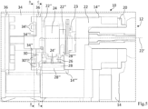
- the locking cylinder 10 also has a drilling protection 20, the cylinder core 22, an electronic control device 23 (cf. Fig.3 u. 5), an electrically and/or electronically operating actuating device 24, a control piece 26 (cf. Figure 3 and 5), a locking element 28, a coupling element 30, a compression spring 32 and a locking bit 34.
- rings 36 can be provided which serve as guide and/or sealing rings.
- the cylinder core 22 is rotatably mounted in the cylinder housing part 14, in a corresponding core channel 14'' (cf. Fig. 2 and 3 ).
- the actuating device 24, the control piece 26, the locking element 28 and the coupling element 30 are arranged on or in the cylinder core 22.
- the actuating device 24 is designed as an electric motor, with the control piece 26 being fixedly attached to its motor shaft 24' in a rotationally fixed manner.
- the control device 23 is electrically and/or electronically connected to the actuating device 24 (cf. Fig.3 and 5 ).
- the control piece 26 can be moved by means of the adjusting device 24 between a blocking position (cf. Fig.3 ) and a Unlocking position (cf. Fig.5 ).
- the control piece 26 can be pivoted by a defined angle by controlling the actuating device 24.
- the locked position the control piece 26 blocks a displacement of the locking element 28 from its locked position (cf. Fig.3 ) into its release position.
- the control piece 26 in the unlocked position allows a displacement of the locking element 28 into its release position (cf. Fig.5 ).
- the control piece 26 can have a locking section and a release section, as explained above.
- the locking element 28 is slidably mounted in the cylinder core 22 and is moved by means of the compression spring 32 in the direction of its locking position (cf. Fig.3 and 4a ) prestressed.
- the displacement direction V of the locking element 28 is oriented orthogonally to the central longitudinal axis 22' of the cylinder core 22 (cf. Fig.2 ).
- the locking element 28 has a base section 28' which is plate-shaped in the example (cf. Fig.2 ).
- a projection 28'' protrudes from this on a flat side, which in the example is convexly rounded, with which the locking element 28 in its locking position engages in a groove 14′′′ formed in the core channel 14'' of the cylinder housing part 14, which is concave in the present case.
- On the other flat side opposite the flat side with projection 28' several, in the example four, raised and parallel pin sections 28′′′ protrude, via which the locking element 28 can be inserted into recesses 22'' in the cylinder core corresponding to the pin sections 28′′′. 22 is guided in a movable manner (cf. Fig.2 , 3 and 4a ).
- the pin sections 28′′′ facing the locking bit 34 have a greater length than the pin sections 28′′′ facing away from the locking bit 34 (cf. Fig.2 and 3 ).
- a pocket 22′′′ is formed in which the coupling element 30 is guided so as to be displaceable along the direction of displacement V, but is rotationally fixed relative to the cylinder core 22.
- the direction of displacement of the coupling element 30 is oriented orthogonally to the central longitudinal axis 22' of the cylinder core 22.
- the direction of displacement of the coupling element 30 is oriented parallel to the direction of displacement of the locking element 28, so that the locking element 28 and the coupling element 30 are guided so as to be displaceable parallel to one another in the cylinder core 22.
- the coupling element 30 has a base section 30' which is delimited on three sides by flat surfaces.
- a fourth side 30'' (in Figure 2 oriented downwards) is rounded.
- the coupling element 30 is adapted to the outer contour of the cylinder core 22.
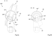
- Two raised and curved, in the example arched ribs 30′′′ protrude from the base section 30' on a flat side facing the locking bit 34 for coupling with the locking bit 34 (cf. Fig.2 , 3 and 4b ).
- the ribs 30′′′ and the counter ribs 34' are aligned with each other in such a way that when the coupling element 30 is in its coupling position (cf. Fig.6b ), the ribs 30''' and counter ribs 34' abut one another in the circumferential direction (ribs 30′′′ continue the contour of the counter ribs 34').
- the locking bit 34 is then coupled in a rotationally fixed manner to the coupling element 30 and/or the cylinder core 22 (cf. Fig.5 and 6b ).
- the ribs 30′′′ and the counter ribs 34' are arranged offset from one another in such a way that the locking bit 34 can rotate freely relative to the coupling element 30 and/or the cylinder core 22 (cf. Fig.3 and 4b ).
- the ribs 30′′′ can then run in spaces between the counter ribs 34'.
- the locking system 100 works as follows:
- the electronic control device 23 checks whether the key 12 is authorized, i.e. whether it has the correct locking secret.
- the actuating device 24 is not activated by the control device 23.
- the control piece 26 therefore remains in the locked position. If an attempt is made to turn the cylinder core 22 using the key 12, the locking element 28 remains in the groove 14′′′ of the cylinder housing part 14. The locking element 28 cannot move in the direction of the control piece 26 or into the cylinder core 22, as the control piece 26 blocks this (see. Fig.3 and 4a ). The cylinder core 22 cannot therefore be rotated.
- the coupling element 30, which is coupled to the locking element 28, does not move due to the lack of a displacement of the locking element 28 in the release position and thus remains in its freewheel position (cf. Fig. 4b ).
- the ribs 30′′′ of the coupling element 30 can thus run in the gaps or the free paths between the counter ribs 34' of the locking bit 34. There is therefore no coupling.
- the locking bit 34 can thus be freely rotated relative to the coupling element 30 and/or the cylinder core 22.
- the actuating device 24 is activated by means of the control device 23, whereby the control piece 26 is moved into the unlocking position (cf. Fig.5 ).
- the control piece 26 is rotated by means of the adjusting device 24 through the motor shaft 24' by a defined angle, for example by an angle of 90°.
- the locking element 28 can be pressed out of the groove 14′′′ of the cylinder housing part 14 (cf. Fig.6a ).
- the locking element 28 dips in the direction of the control piece 26 or into the cylinder core 22 (release position).
- the cylinder core 22 can now rotate freely.
- the coupling element 30, which is coupled to the locking element 28, is displaced as a result of a displacement of the locking element 28, which dips into the cylinder core 22 or moves towards the central longitudinal axis 22' of the cylinder core 22, also into the cylinder core 22 or in the direction of the central longitudinal axis 22' of the cylinder core 22 (cf. Fig.6b ).
- the coupling element 30 assumes its coupling position, whereby the ribs 30′′′ and the counter ribs 34' are aligned with each other or rest against each other (ribs 30′′′ continue the contour of the counter ribs 34').
- the locking bit 34 is rotationally fixed to the Coupling element 30 and/or the cylinder core 22. When the cylinder core 22 is rotated by means of key operation, the locking bit 34 rotates accordingly.
- the proposed design has the advantage that the locking bit 34 is only coupled to the (outside) cylinder core 22 in a rotationally fixed manner when the cylinder core 22 is operated or rotated by an authorized key 12. If the cylinder core 22 is not rotated or the control piece 26 is in the locked position, the locking bit 34 remains decoupled. As a result, the locking bit 34 can be operated from the inside, for example by an (inside) knob cylinder or an (inside) locking cylinder, whereby the knob cylinder or the (inside) locking cylinder are coupled to the locking bit 34 in a rotationally fixed manner. This allows the locking cylinder 10 to be operated from the inside, for example as part of an emergency function, even if the (outside) cylinder core 22 is locked.
Landscapes
- Physics & Mathematics (AREA)
- Electromagnetism (AREA)
- Engineering & Computer Science (AREA)
- Mechanical Engineering (AREA)
- Lock And Its Accessories (AREA)
Priority Applications (4)
| Application Number | Priority Date | Filing Date | Title |
|---|---|---|---|
| EP22187412.6A EP4311900B1 (de) | 2022-07-28 | 2022-07-28 | Schliesssystem mit mechatronischem schliesszylinder und mechatronischem schlüssel |
| ES22187412T ES2993483T3 (en) | 2022-07-28 | 2022-07-28 | Locking system with mechatronic locking cylinder and a mechatronic key |
| PL22187412.6T PL4311900T3 (pl) | 2022-07-28 | 2022-07-28 | System zamykający z mechatroniczną wkładką zamka i kluczem mechatronicznym |
| HRP20241635TT HRP20241635T1 (hr) | 2022-07-28 | 2022-07-28 | Sustav zaključavanja s mehatroničkim cilindrom zaključavanja i mehatroničkim ključem |
Applications Claiming Priority (1)
| Application Number | Priority Date | Filing Date | Title |
|---|---|---|---|
| EP22187412.6A EP4311900B1 (de) | 2022-07-28 | 2022-07-28 | Schliesssystem mit mechatronischem schliesszylinder und mechatronischem schlüssel |
Publications (2)
| Publication Number | Publication Date |
|---|---|
| EP4311900A1 EP4311900A1 (de) | 2024-01-31 |
| EP4311900B1 true EP4311900B1 (de) | 2024-09-04 |
Family
ID=82781227
Family Applications (1)
| Application Number | Title | Priority Date | Filing Date |
|---|---|---|---|
| EP22187412.6A Active EP4311900B1 (de) | 2022-07-28 | 2022-07-28 | Schliesssystem mit mechatronischem schliesszylinder und mechatronischem schlüssel |
Country Status (4)
| Country | Link |
|---|---|
| EP (1) | EP4311900B1 (pl) |
| ES (1) | ES2993483T3 (pl) |
| HR (1) | HRP20241635T1 (pl) |
| PL (1) | PL4311900T3 (pl) |
Family Cites Families (4)
| Publication number | Priority date | Publication date | Assignee | Title |
|---|---|---|---|---|
| DE3800823A1 (de) * | 1987-08-19 | 1989-07-27 | Bks Gmbh | Schliesszylinder, insbesondere fuer einsteckschloesser bestimmter profilzylinder |
| IL149876A (en) * | 2002-05-27 | 2009-09-22 | Mul T Lock Technologies Ltd | Lock |
| DE102009005322B4 (de) | 2009-01-16 | 2013-11-14 | Martin Lehmann Gmbh & Co. Kg | Elektronische Möbelschließeinheit |
| US8544302B2 (en) * | 2010-01-25 | 2013-10-01 | Knock N'lock Ltd. | Door cylinder lock |
-
2022
- 2022-07-28 ES ES22187412T patent/ES2993483T3/es active Active
- 2022-07-28 HR HRP20241635TT patent/HRP20241635T1/hr unknown
- 2022-07-28 EP EP22187412.6A patent/EP4311900B1/de active Active
- 2022-07-28 PL PL22187412.6T patent/PL4311900T3/pl unknown
Also Published As
| Publication number | Publication date |
|---|---|
| PL4311900T3 (pl) | 2025-01-27 |
| HRP20241635T1 (hr) | 2025-02-14 |
| ES2993483T3 (en) | 2024-12-30 |
| EP4311900A1 (de) | 2024-01-31 |
Similar Documents
| Publication | Publication Date | Title |
|---|---|---|
| EP1842989B1 (de) | Einsteckschloss | |
| DE2711061C2 (de) | Permanentmagnet-Schlüssel betätigbares Schloß | |
| EP2372054B1 (de) | Permutationsschloss | |
| EP0819810B1 (de) | Beschlag für ein Schloss | |
| EP0977929A1 (de) | Schliessvorrichtung | |
| EP4150178A1 (de) | Hangschloss-grundbausatz und hangschloss-system | |
| DE19603200C2 (de) | Elektronisches Türschloß | |
| DE2433322C3 (de) | Panik-Hauptschloß mit Fallen-Nebenverschlüssen | |
| EP2010739B1 (de) | Kraftfahrzeugtürverschluss | |
| DE69701236T2 (de) | Einsteckschloss | |
| EP2218850B1 (de) | Schließsystem mit Kupplungseinrichtung für einen zwei Zylinderkerne beinhaltenden Doppelschließzylinder mit Not- und Gefahrenfunktion und mit zugeordneten Schlüssel | |
| DE102004048231B4 (de) | Automatische Rückstellvorrichtung | |
| EP0471976B1 (de) | Treibstangenschloss | |
| EP4311900B1 (de) | Schliesssystem mit mechatronischem schliesszylinder und mechatronischem schlüssel | |
| DE4244414C2 (de) | Verschluß für Fenster, Türen u. dgl. | |
| EP4190999A1 (de) | Sperrvorrichtung mit einem stator, mit einem rotor und mit einer abziehschutzvorrichtung | |
| EP2862992B1 (de) | Multischloss | |
| EP0835975B1 (de) | Schliesszylinder | |
| DE3526173A1 (de) | Schluessel fuer zwei in unterschiedlichen drehrichtungen entsperrbare schliesszylinder | |
| DE19738244C2 (de) | Schloß für Sicherheitstüren | |
| EP1164238A1 (de) | Schliesszylinder | |
| EP4191002A1 (de) | Sperrvorrichtung für ein verschlusselement oder ein schaltelement | |
| DE2605763C3 (de) | Treibstangenschloß mit Falle | |
| AT413844B (de) | Schliesseinrichtung | |
| DE19709331C2 (de) | Schließvorrichtung mit einem Möbelschloß sowie einem Drehelement |
Legal Events
| Date | Code | Title | Description |
|---|---|---|---|
| REG | Reference to a national code |
Ref country code: HR Ref legal event code: TUEP Ref document number: P20241635T Country of ref document: HR |
|
| PUAI | Public reference made under article 153(3) epc to a published international application that has entered the european phase |
Free format text: ORIGINAL CODE: 0009012 |
|
| STAA | Information on the status of an ep patent application or granted ep patent |
Free format text: STATUS: REQUEST FOR EXAMINATION WAS MADE |
|
| 17P | Request for examination filed |
Effective date: 20230317 |
|
| AK | Designated contracting states |
Kind code of ref document: A1 Designated state(s): AL AT BE BG CH CY CZ DE DK EE ES FI FR GB GR HR HU IE IS IT LI LT LU LV MC MK MT NL NO PL PT RO RS SE SI SK SM TR |
|
| GRAP | Despatch of communication of intention to grant a patent |
Free format text: ORIGINAL CODE: EPIDOSNIGR1 |
|
| STAA | Information on the status of an ep patent application or granted ep patent |
Free format text: STATUS: GRANT OF PATENT IS INTENDED |
|
| RIC1 | Information provided on ipc code assigned before grant |
Ipc: E05B 47/00 20060101ALN20240226BHEP Ipc: E05B 9/04 20060101ALN20240226BHEP Ipc: E05B 47/06 20060101ALI20240226BHEP Ipc: E05B 17/04 20060101ALI20240226BHEP Ipc: E05B 9/10 20060101AFI20240226BHEP |
|
| INTG | Intention to grant announced |
Effective date: 20240320 |
|
| GRAS | Grant fee paid |
Free format text: ORIGINAL CODE: EPIDOSNIGR3 |
|
| GRAA | (expected) grant |
Free format text: ORIGINAL CODE: 0009210 |
|
| STAA | Information on the status of an ep patent application or granted ep patent |
Free format text: STATUS: THE PATENT HAS BEEN GRANTED |
|
| P01 | Opt-out of the competence of the unified patent court (upc) registered |
Free format text: CASE NUMBER: APP_40507/2024 Effective date: 20240709 |
|
| AK | Designated contracting states |
Kind code of ref document: B1 Designated state(s): AL AT BE BG CH CY CZ DE DK EE ES FI FR GB GR HR HU IE IS IT LI LT LU LV MC MK MT NL NO PL PT RO RS SE SI SK SM TR |
|
| REG | Reference to a national code |
Ref country code: GB Ref legal event code: FG4D Free format text: NOT ENGLISH |
|
| REG | Reference to a national code |
Ref country code: CH Ref legal event code: EP |
|
| REG | Reference to a national code |
Ref country code: NL Ref legal event code: FP |
|
| REG | Reference to a national code |
Ref country code: IE Ref legal event code: FG4D Free format text: LANGUAGE OF EP DOCUMENT: GERMAN |
|
| REG | Reference to a national code |
Ref country code: DE Ref legal event code: R096 Ref document number: 502022001605 Country of ref document: DE |
|
| REG | Reference to a national code |
Ref country code: SK Ref legal event code: T3 Ref document number: E 45149 Country of ref document: SK |
|
| REG | Reference to a national code |
Ref country code: LT Ref legal event code: MG9D |
|
| REG | Reference to a national code |
Ref country code: ES Ref legal event code: FG2A Ref document number: 2993483 Country of ref document: ES Kind code of ref document: T3 Effective date: 20241230 |
|
| PG25 | Lapsed in a contracting state [announced via postgrant information from national office to epo] |
Ref country code: NO Free format text: LAPSE BECAUSE OF FAILURE TO SUBMIT A TRANSLATION OF THE DESCRIPTION OR TO PAY THE FEE WITHIN THE PRESCRIBED TIME-LIMIT Effective date: 20241204 |
|
| PG25 | Lapsed in a contracting state [announced via postgrant information from national office to epo] |
Ref country code: GR Free format text: LAPSE BECAUSE OF FAILURE TO SUBMIT A TRANSLATION OF THE DESCRIPTION OR TO PAY THE FEE WITHIN THE PRESCRIBED TIME-LIMIT Effective date: 20241205 Ref country code: FI Free format text: LAPSE BECAUSE OF FAILURE TO SUBMIT A TRANSLATION OF THE DESCRIPTION OR TO PAY THE FEE WITHIN THE PRESCRIBED TIME-LIMIT Effective date: 20240904 |
|
| PG25 | Lapsed in a contracting state [announced via postgrant information from national office to epo] |
Ref country code: BG Free format text: LAPSE BECAUSE OF FAILURE TO SUBMIT A TRANSLATION OF THE DESCRIPTION OR TO PAY THE FEE WITHIN THE PRESCRIBED TIME-LIMIT Effective date: 20240904 |
|
| PG25 | Lapsed in a contracting state [announced via postgrant information from national office to epo] |
Ref country code: LV Free format text: LAPSE BECAUSE OF FAILURE TO SUBMIT A TRANSLATION OF THE DESCRIPTION OR TO PAY THE FEE WITHIN THE PRESCRIBED TIME-LIMIT Effective date: 20240904 |
|
| PG25 | Lapsed in a contracting state [announced via postgrant information from national office to epo] |
Ref country code: RS Free format text: LAPSE BECAUSE OF FAILURE TO SUBMIT A TRANSLATION OF THE DESCRIPTION OR TO PAY THE FEE WITHIN THE PRESCRIBED TIME-LIMIT Effective date: 20241204 |
|
| PG25 | Lapsed in a contracting state [announced via postgrant information from national office to epo] |
Ref country code: RS Free format text: LAPSE BECAUSE OF FAILURE TO SUBMIT A TRANSLATION OF THE DESCRIPTION OR TO PAY THE FEE WITHIN THE PRESCRIBED TIME-LIMIT Effective date: 20241204 Ref country code: NO Free format text: LAPSE BECAUSE OF FAILURE TO SUBMIT A TRANSLATION OF THE DESCRIPTION OR TO PAY THE FEE WITHIN THE PRESCRIBED TIME-LIMIT Effective date: 20241204 Ref country code: LV Free format text: LAPSE BECAUSE OF FAILURE TO SUBMIT A TRANSLATION OF THE DESCRIPTION OR TO PAY THE FEE WITHIN THE PRESCRIBED TIME-LIMIT Effective date: 20240904 Ref country code: GR Free format text: LAPSE BECAUSE OF FAILURE TO SUBMIT A TRANSLATION OF THE DESCRIPTION OR TO PAY THE FEE WITHIN THE PRESCRIBED TIME-LIMIT Effective date: 20241205 Ref country code: FI Free format text: LAPSE BECAUSE OF FAILURE TO SUBMIT A TRANSLATION OF THE DESCRIPTION OR TO PAY THE FEE WITHIN THE PRESCRIBED TIME-LIMIT Effective date: 20240904 Ref country code: BG Free format text: LAPSE BECAUSE OF FAILURE TO SUBMIT A TRANSLATION OF THE DESCRIPTION OR TO PAY THE FEE WITHIN THE PRESCRIBED TIME-LIMIT Effective date: 20240904 |
|
| REG | Reference to a national code |
Ref country code: HR Ref legal event code: T1PR Ref document number: P20241635 Country of ref document: HR |
|
| PG25 | Lapsed in a contracting state [announced via postgrant information from national office to epo] |
Ref country code: IS Free format text: LAPSE BECAUSE OF FAILURE TO SUBMIT A TRANSLATION OF THE DESCRIPTION OR TO PAY THE FEE WITHIN THE PRESCRIBED TIME-LIMIT Effective date: 20250104 Ref country code: PT Free format text: LAPSE BECAUSE OF FAILURE TO SUBMIT A TRANSLATION OF THE DESCRIPTION OR TO PAY THE FEE WITHIN THE PRESCRIBED TIME-LIMIT Effective date: 20250106 |
|
| PG25 | Lapsed in a contracting state [announced via postgrant information from national office to epo] |
Ref country code: SM Free format text: LAPSE BECAUSE OF FAILURE TO SUBMIT A TRANSLATION OF THE DESCRIPTION OR TO PAY THE FEE WITHIN THE PRESCRIBED TIME-LIMIT Effective date: 20240904 |
|
| PG25 | Lapsed in a contracting state [announced via postgrant information from national office to epo] |
Ref country code: EE Free format text: LAPSE BECAUSE OF FAILURE TO SUBMIT A TRANSLATION OF THE DESCRIPTION OR TO PAY THE FEE WITHIN THE PRESCRIBED TIME-LIMIT Effective date: 20240904 |
|
| PG25 | Lapsed in a contracting state [announced via postgrant information from national office to epo] |
Ref country code: CZ Free format text: LAPSE BECAUSE OF FAILURE TO SUBMIT A TRANSLATION OF THE DESCRIPTION OR TO PAY THE FEE WITHIN THE PRESCRIBED TIME-LIMIT Effective date: 20240904 |
|
| REG | Reference to a national code |
Ref country code: DE Ref legal event code: R097 Ref document number: 502022001605 Country of ref document: DE |
|
| PGFP | Annual fee paid to national office [announced via postgrant information from national office to epo] |
Ref country code: PL Payment date: 20250618 Year of fee payment: 4 |
|
| PG25 | Lapsed in a contracting state [announced via postgrant information from national office to epo] |
Ref country code: DK Free format text: LAPSE BECAUSE OF FAILURE TO SUBMIT A TRANSLATION OF THE DESCRIPTION OR TO PAY THE FEE WITHIN THE PRESCRIBED TIME-LIMIT Effective date: 20240904 |
|
| PLBE | No opposition filed within time limit |
Free format text: ORIGINAL CODE: 0009261 |
|
| STAA | Information on the status of an ep patent application or granted ep patent |
Free format text: STATUS: NO OPPOSITION FILED WITHIN TIME LIMIT |
|
| 26N | No opposition filed |
Effective date: 20250605 |
|
| REG | Reference to a national code |
Ref country code: HR Ref legal event code: ODRP Ref document number: P20241635 Country of ref document: HR Payment date: 20250717 Year of fee payment: 4 |
|
| PGFP | Annual fee paid to national office [announced via postgrant information from national office to epo] |
Ref country code: NL Payment date: 20250721 Year of fee payment: 4 |
|
| PG25 | Lapsed in a contracting state [announced via postgrant information from national office to epo] |
Ref country code: SE Free format text: LAPSE BECAUSE OF FAILURE TO SUBMIT A TRANSLATION OF THE DESCRIPTION OR TO PAY THE FEE WITHIN THE PRESCRIBED TIME-LIMIT Effective date: 20240904 |
|
| REG | Reference to a national code |
Ref country code: DE Ref legal event code: R082 Ref document number: 502022001605 Country of ref document: DE |
|
| PGFP | Annual fee paid to national office [announced via postgrant information from national office to epo] |
Ref country code: ES Payment date: 20250828 Year of fee payment: 4 |
|
| PGFP | Annual fee paid to national office [announced via postgrant information from national office to epo] |
Ref country code: DE Payment date: 20250722 Year of fee payment: 4 |
|
| PGFP | Annual fee paid to national office [announced via postgrant information from national office to epo] |
Ref country code: IT Payment date: 20250731 Year of fee payment: 4 |
|
| PGFP | Annual fee paid to national office [announced via postgrant information from national office to epo] |
Ref country code: BE Payment date: 20250721 Year of fee payment: 4 |
|
| PGFP | Annual fee paid to national office [announced via postgrant information from national office to epo] |
Ref country code: HR Payment date: 20250717 Year of fee payment: 4 |
|
| PGFP | Annual fee paid to national office [announced via postgrant information from national office to epo] |
Ref country code: FR Payment date: 20250725 Year of fee payment: 4 Ref country code: AT Payment date: 20251020 Year of fee payment: 4 |
|
| PGFP | Annual fee paid to national office [announced via postgrant information from national office to epo] |
Ref country code: RO Payment date: 20250722 Year of fee payment: 4 |
|
| PGFP | Annual fee paid to national office [announced via postgrant information from national office to epo] |
Ref country code: SK Payment date: 20250725 Year of fee payment: 4 |
|
| REG | Reference to a national code |
Ref country code: CH Ref legal event code: H13 Free format text: ST27 STATUS EVENT CODE: U-0-0-H10-H13 (AS PROVIDED BY THE NATIONAL OFFICE) Effective date: 20260224 |
|
| PG25 | Lapsed in a contracting state [announced via postgrant information from national office to epo] |
Ref country code: LU Free format text: LAPSE BECAUSE OF NON-PAYMENT OF DUE FEES Effective date: 20250728 |