EP4310377A1 - Joint de peigne et procédé associé - Google Patents
Joint de peigne et procédé associé Download PDFInfo
- Publication number
- EP4310377A1 EP4310377A1 EP23401020.5A EP23401020A EP4310377A1 EP 4310377 A1 EP4310377 A1 EP 4310377A1 EP 23401020 A EP23401020 A EP 23401020A EP 4310377 A1 EP4310377 A1 EP 4310377A1
- Authority
- EP
- European Patent Office
- Prior art keywords
- sealing
- webs
- base body
- pipe
- mat
- Prior art date
- Legal status (The legal status is an assumption and is not a legal conclusion. Google has not performed a legal analysis and makes no representation as to the accuracy of the status listed.)
- Pending
Links
- 238000000034 method Methods 0.000 title claims abstract description 15
- 238000007789 sealing Methods 0.000 claims abstract description 238
- 239000000463 material Substances 0.000 claims description 48
- 230000007704 transition Effects 0.000 description 12
- 229920001971 elastomer Polymers 0.000 description 9
- 230000008961 swelling Effects 0.000 description 9
- 238000005520 cutting process Methods 0.000 description 8
- 238000004519 manufacturing process Methods 0.000 description 7
- 230000035515 penetration Effects 0.000 description 7
- 229920002725 thermoplastic elastomer Polymers 0.000 description 7
- 239000000806 elastomer Substances 0.000 description 6
- 239000007788 liquid Substances 0.000 description 6
- 230000006835 compression Effects 0.000 description 5
- 238000007906 compression Methods 0.000 description 5
- 239000004033 plastic Substances 0.000 description 4
- 229920003023 plastic Polymers 0.000 description 4
- 239000000853 adhesive Substances 0.000 description 3
- 230000001070 adhesive effect Effects 0.000 description 3
- 230000005484 gravity Effects 0.000 description 3
- 238000001746 injection moulding Methods 0.000 description 3
- 229920001169 thermoplastic Polymers 0.000 description 3
- 229920001187 thermosetting polymer Polymers 0.000 description 3
- 239000004416 thermosoftening plastic Substances 0.000 description 3
- XLYOFNOQVPJJNP-UHFFFAOYSA-N water Substances O XLYOFNOQVPJJNP-UHFFFAOYSA-N 0.000 description 3
- 238000010521 absorption reaction Methods 0.000 description 2
- 239000000654 additive Substances 0.000 description 2
- 230000004323 axial length Effects 0.000 description 2
- 230000006378 damage Effects 0.000 description 2
- 230000007423 decrease Effects 0.000 description 2
- 238000001125 extrusion Methods 0.000 description 2
- 238000000465 moulding Methods 0.000 description 2
- 229920001296 polysiloxane Polymers 0.000 description 2
- 238000003825 pressing Methods 0.000 description 2
- 238000004080 punching Methods 0.000 description 2
- 239000003566 sealing material Substances 0.000 description 2
- 238000004026 adhesive bonding Methods 0.000 description 1
- 229910000278 bentonite Inorganic materials 0.000 description 1
- 239000000440 bentonite Substances 0.000 description 1
- SVPXDRXYRYOSEX-UHFFFAOYSA-N bentoquatam Chemical compound O.O=[Si]=O.O=[Al]O[Al]=O SVPXDRXYRYOSEX-UHFFFAOYSA-N 0.000 description 1
- 230000015572 biosynthetic process Effects 0.000 description 1
- 238000005266 casting Methods 0.000 description 1
- 239000002131 composite material Substances 0.000 description 1
- 150000001875 compounds Chemical class 0.000 description 1
- 230000000694 effects Effects 0.000 description 1
- 239000013013 elastic material Substances 0.000 description 1
- 238000005755 formation reaction Methods 0.000 description 1
- 239000012528 membrane Substances 0.000 description 1
- 229920000058 polyacrylate Polymers 0.000 description 1
- 239000006228 supernatant Substances 0.000 description 1
- 230000002522 swelling effect Effects 0.000 description 1
- 238000004078 waterproofing Methods 0.000 description 1
Images


Classifications
-
- F—MECHANICAL ENGINEERING; LIGHTING; HEATING; WEAPONS; BLASTING
- F16—ENGINEERING ELEMENTS AND UNITS; GENERAL MEASURES FOR PRODUCING AND MAINTAINING EFFECTIVE FUNCTIONING OF MACHINES OR INSTALLATIONS; THERMAL INSULATION IN GENERAL
- F16L—PIPES; JOINTS OR FITTINGS FOR PIPES; SUPPORTS FOR PIPES, CABLES OR PROTECTIVE TUBING; MEANS FOR THERMAL INSULATION IN GENERAL
- F16L5/00—Devices for use where pipes, cables or protective tubing pass through walls or partitions
- F16L5/02—Sealing
- F16L5/10—Sealing by using sealing rings or sleeves only
-
- E—FIXED CONSTRUCTIONS
- E04—BUILDING
- E04G—SCAFFOLDING; FORMS; SHUTTERING; BUILDING IMPLEMENTS OR AIDS, OR THEIR USE; HANDLING BUILDING MATERIALS ON THE SITE; REPAIRING, BREAKING-UP OR OTHER WORK ON EXISTING BUILDINGS
- E04G15/00—Forms or shutterings for making openings, cavities, slits, or channels
- E04G15/06—Forms or shutterings for making openings, cavities, slits, or channels for cavities or channels in walls of floors, e.g. for making chimneys
- E04G15/061—Non-reusable forms
Definitions
- the invention relates to a sealing mat for sealing a bushing, in particular for sealing a pipe bushing according to claim 1.
- the invention also relates to a sealed pipe bushing, comprising a pipe and a sealing mat according to claim 7.
- the invention relates to a method for sealing a bushing, in particular for sealing a pipe bushing according to claim 9.
- Pipe seals, sealing rings, etc. are generally known from the prior art.
- the known seals are designed for a specific pipe diameter.
- the invention includes the technical teaching that in a sealing mat for sealing a bushing, in particular for sealing a pipe bushing, comprising a flat base body which extends over a base plane, with an upper side and a lower side, it is provided that at least one of the Sealing projections or sealing webs protrude transversely to the base plane on both sides, the sealing projections or sealing webs being spaced radially differently from a center line projecting vertically through a center of the base plane or the base body or the sealing mat, so that a bushing can be sealingly received between the sealing projections or sealing webs.
- a center of the base level is in particular the center of an area intended for a feedthrough, thus a later recess.
- the sealing mat is intended for sealing pipe penetrations with different external dimensions such as outer diameter or outer circumference.
- the pipe bushings can have different shapes in the cross-sectional direction.
- the pipe bushing can be designed to be rotationally symmetrical (ring-shaped or circular) or not rotationally symmetrical (oval, square, rectangular, polygonal), at least with respect to its outer contour.
- the base body has an area for a through opening, a through opening or a prepared through opening through which a pipe can be passed.
- Means can be provided to simplify the production of the through opening, for example in the form of cutting or punching aids. Such means may include grooves, depressions, perforations, markings, projections and the like. Only through openings or recesses are listed below, whereby, unless expressly stated otherwise, prepared through openings or recesses or areas for through openings may also be included.
- a through opening can be subsequently produced in a simple manner.
- Different means for producing through openings are provided for passage openings of different sizes. These means for producing through openings can be produced early in the manufacturing process of the sealing mat, i.e. before the dimensions of the pipe bushing to be sealed are known.
- the through opening itself - i.e. without means - can only be produced after the dimensions of the through opening are known.
- the sealing mat is preferably intended for hollow cylindrical pipes, so that the through opening preferably has a circular cross section.
- the through opening is preferably arranged centrally.
- the contour of the Through opening corresponds to the outer contour of the pipe to be accommodated.
- the flat base body is preferably designed like a disk or mat and can have any desired (cross-sectional) shape in a top view. Accordingly, the base body has a significantly smaller dimension in one spatial direction than in the other two spatial directions. Preferably, the dimension is designed to be constant in the direction of the spatial direction with the smallest dimension, i.e. in the direction of the base body thickness. In other embodiments, the base body thickness is variable or designed differently.
- the material of the base body is preferably an elastic material which is suitable for sealing, in particular sealing against water.
- the base body is made of a building-sealing material.
- the base body material is a material that is suitable for penetrations or pipe bushings.
- These can be suitable plastic, rubber, silicone and/or swellable materials.
- the materials may generally be swellable materials and/or non-swellable materials. In principle, all materials that can be processed into shapes are used as materials.
- Preferably, partially cross-linked and/or completely cross-linked elastomer materials or thermoelastic elastomers (TPE) are used, which are made swellable by organic or inorganic additives.
- Swellable additives here are preferably partially neutralized polyacrylate and/or bentonite.
- materials from the classes of elastomers, thermoplastics, thermoplastic elastomers and thermosets are preferred for the sealing mat and/or the sealing webs or sealing projections, preferably materials from the class of thermoplastic elastomers.
- the production of the projections or webs, which function as a sealing ring during sealing can be carried out using methods of rubber and/or thermoplastic and/or thermoset processing, for example by means of extrusion, injection molding, pressing, etc. Preferably the production takes place by means of injection molding.
- the material for the sealing mat and/or for the sealing webs or sealing projections has a suitable hardness, in particular a Shore hardness.
- DIN ISO 7619-1 Elastomers or thermoplastic elastomers - Determination of penetration hardness - Part 1: Durometer method (Shore hardness) is used to determine, define and characterize Shore hardness.
- the Shore hardness of the seal is preferably in the range 20 to 85 Shore A, more preferably in the range 40 to 70 Shore A.
- the material for the sealing mat and/or the sealing webs or sealing projections - or sealing rings - has a suitable elongation or elasticity.
- the elongations at break of the materials are preferably in the range from 50 to 800%, more preferably in the range from 150 to 450%.
- the materials for the sealing mat and/or sealing projections or sealing webs have a suitable compression set.
- the compression set is preferably in the range of 0 to 95% (24 h, 23 °C), more preferably in the range of 0 to 40% (24 h, 23 °C).
- the materials for the sealing mat and/or sealing projections or sealing webs have suitable swelling properties.
- the material for the seal (base body, webs, projections, sealing rings) includes or consists of a swellable material. If a leak occurs, liquid (e.g. water from the ground) reaches the seal. This swells as liquid is stored, thereby increasing its volume and sealing the resulting leak securely, independently and permanently off again.
- the method of liquid absorption with free swelling (Free Swelling Capacity - FSC value) is used to determine, define and characterize the swelling. With this method, a material sample is placed in liquid and can swell without restricting the swelling process. The relative increase in mass of the material sample is determined as a function of time.
- the relative mass increase is defined as the liquid mass absorbed based on the dry sample mass and is given in percent. A relative liquid absorption of 100% corresponds to a doubling of the dry sample mass.
- the seal has relative mass increases, in swelling equilibrium, of preferably 10 to 800%, more preferably relative mass increases of 50 to 125%. The swelling equilibrium is preferably reached after 5 to 500 hours, more preferably the swelling equilibrium is reached after 10 to 72 hours.
- the material from which the sealing mat and/or the sealing projections and/or sealing webs is made is selected from the group comprising elastomers, thermoplastics, thermoplastic elastomers and thermosets. Materials from the class of thermoplastic elastomers are preferably used.
- the base body has a top and an opposite bottom.
- sealing webs or sealing projections - hereinafter referred to as webs - protrude transversely from the base body.
- the webs can project at any angle transversely from the base body, more precisely one side of the base body, for example the top.
- the webs preferably protrude essentially at right angles or at an angle of greater than 60 degrees, preferably greater than 70 degrees and most preferably greater than 80 degrees and/or less than 120 degrees, preferably less than 110 degrees and most preferably less than 100 degrees from the corresponding side .
- the plurality of sealing webs can be connected to one another and arranged adjacent to one another in the axial direction of the imaginary center line through the center.
- the sealing webs can also be designed to be radially spaced apart from one another in the direction of the main extension of the base body, thus at right angles to the imaginary center line.
- the individual webs do not contact each other, but only contact the base body.
- a combination of webs that are adjacent to one another and do not contact one another is also provided in one embodiment.
- the webs are designed as webs or web rings that are spaced apart from one another and protrude from one side of the base body.
- the webs are designed as adjacent or adjacent webs or web rings. In the embodiment in which the webs do not contact each other, a radial distance is provided between the webs.
- the webs are arranged horizontally on one level - the base body.
- the webs have a radial offset from one another and are arranged at different axial distances from the base body. A transition section or intermediate section can be provided between adjacent webs.
- the sealing webs form a polygonal shape, at least in a side or cross-sectional view.
- a sealing web with a first radial distance from the center line adjoins another sealing web that adjoins it with a different radial distance.
- the next sealing web again with a different radial distance, adjoins the previous sealing web, so that a kind of polygon, pyramid or cone shape results in the axial direction of the center line.
- the transitions of the sealing webs can be continuous or abrupt. In the case of a continuous transition, the radial distances between the sealing webs are also designed to change continuously. A crack-free lateral surface or outside is created.
- intermediate sections or transition sections are provided between the sealing webs or, more precisely, sealing sections.
- the transition section opens into the other sealing webs at an angle.
- the angle can be a right angle.
- a different angle is provided.
- a subsequent sealing web also protrudes at an angle from the transition section. This allows at least two sealing webs, in one embodiment all of them Sealing webs can be designed perpendicular to the base body, while the transition sections between two adjacent sealing webs are arranged at an angle not equal to or equal to 90 degrees to the base body. In a continuous embodiment, the webs are arranged at an angle not equal to 90° to the base body and protrude from the base body as inclined to it.
- sealing web rests on a pipe that is passed through and is guided vertically through the base body.
- sealing webs projecting at 90° at least almost the entire sealing web rests on the inside of the pipe through which it is inserted. If a transition section is provided, it does not rest on the pipe being passed through.
- the sealing webs When the sealing webs are lined up axially, the sealing web that projects directly from the base body has the greatest radial distance from the center line through the center.
- the sealing webs and/or transition sections adjoining it in the axial direction have radial distances from the center line that become smaller or taper as the axial distance from the base body increases.
- the sealing webs themselves are of the same length in the direction of projection and therefore have the same length in the direction of extension and/or transversely to the direction of extension.
- at least two webs are of different lengths in the direction of extension and/or dimensioned transversely to the direction of extension.
- all webs can also be dimensioned differently in the direction of extension and/or transversely to the direction of extension.
- the direction of extension is preferably the axial direction (the center line).
- the webs have a material thickness. In one embodiment, this is designed to be constant along the direction of extension. In other embodiments, the material thickness can vary along the direction of extension, for example, it can taper. In one embodiment, all webs have the same material thickness and/or the same material thickness progression along the direction of extension. In other embodiments, the material thickness varies along the direction of extension between at least two webs. In one embodiment, the webs for demolding in a manufacturing process such as injection molding, a suitable shape, for example a taper in the direction away from the base body. This taper provided for demolding can be provided both for webs with otherwise constant material thickness and for webs with at least partially varying material thickness.
- the webs are at least radially spaced apart from one another - horizontally or in the plane of the base body or vertically or axially in the case of existing transition sections. At least the webs are at a different distance radially from the central axis. In one embodiment, the webs are spaced radially equidistant from one another and/or from the central axis. In another embodiment, the webs are spaced radially differently from one another and/or from the central axis. Preferably, at least two of the webs are spaced differently radially from one another and/or radially from a central axis.
- the distance between the webs or sections of the webs radially from one another and/or from the central axis is at least such that a tube can be accommodated between the webs.
- This means that the radial distance between two adjacent webs and/or to the central axis is at least as large as the wall thickness of a pipe to be accommodated. In the case of a continuous axial alignment, this applies to sections of the respective sealing web.
- sealing projections or sealing webs are separately connected to the base body via corresponding connecting means.
- sealing projections or sealing webs and the base body are at least partially formed in one piece or at least partially in multiple parts with one another.
- a one-piece embodiment of the sealing mat is preferred.
- the sealing projections or sealing webs and the base body are formed in one piece with one another. In another embodiment, the sealing projections or sealing webs and the base body are formed in several parts together. In yet another embodiment, the sealing projections or sealing webs and the base body are at least partially formed in one piece and at least partially in multiple parts with one another.
- the web material corresponds to the base body material in a one-piece design with the base body.
- the materials for webs or projections and base body can be at least partially the same or at least partially different.
- the projections or webs can be connected to the base body in a detachable manner - non-destructively or with at least partial destruction - or non-detachably, that is to say only with destruction of at least parts of the base body and the web or the projection.
- the connection can be any.
- the connection is made in a cohesive manner, for example by gluing.
- the connection is designed to be form-fitting.
- the connection is designed to be non-positive. Combinations of this are also possible.
- additional webs or projections can be subsequently attached to or detached from the base body.
- the base body is designed in a disk-like or mat-like manner, for example as a web material.
- the disk-like base body is preferably designed as a circular disk with a circular cross section when viewed from above. Other shapes such as rectangles, polygons, ovals and the like are also possible.
- the sealing projections or the sealing webs are formed circumferentially around a center of the base body, so that in a plan view they are formed like a ring and/or as concentric rings.
- the center of the base body is preferably the center of the area for the recess or passage or the center or center of gravity of the area for the passage.
- the central axis is congruent with the central axis of the pipe.
- the webs are designed in other shapes all around. If the webs are designed all around in a horizontal orientation, the webs only have an upper wall and two side walls. The webs form a closed shape, preferably as a circular ring.
- the webs can also be designed as non-circumferential webs, thus as web sections. These then point next to the three Walls listed above have two further end walls. Circumferential webs are preferred for sealing pipe penetrations.
- the webs preferably run around a center of the base body or the center of the passage of the recess for the pipe passage. For a circular disk, this corresponds to the center of the disk. In other embodiments, this may generally be the center of gravity or the center of the area.
- the center preferably forms the center or imaginary center of gravity of the recess, through which the imaginary axial center line runs, which in the case of a pipe feedthrough then also lies on the central axis of the pipe.
- a through opening is provided between the webs, preferably in or around a center or around a center point.
- a pipe can be passed through the through opening.
- the through opening borders on a web or an imaginary continuation of the web. In this way, the sealing mat creates a seal for a pipe bushing.
- Yet another embodiment provides that on a side opposite the side with the projecting sealing projections or sealing webs and/or and/or the inside and/or outside of the sealing projections or webs and/or on those of the transition sections, aids for producing a through opening or Recesses such as notches, material thinnings and/or recesses are provided.
- the base body preferably has webs on only one side, for example on the top. Accordingly, the aids or aids for producing a through opening, such as notches, material thinnings and / or recesses on the underside in an embodiment in which the webs protrude directly from the base body and / or on the inside and / or outside of the webs an axial alignment of the webs is provided.
- the aids are arranged offset from the continuation of the webs towards the underside and/or inside and/or outside.
- the aids preferably run offset to an inner wall of the webs.
- the inner wall or inner wall of the webs is the wall that faces the center of the base body.
- the aids are preferably rotating Aids trained. This means that the aids run at equal distances from the continuation of the webs.
- the aids are each arranged closer to the inner wall of a web than to the outer wall of the adjacent web.
- the outer wall of a web is opposite the inner wall.
- the aids can also be formed on the transition sections, in particular with an axial alignment of the webs.
- the shape of the aids such as notches, material thinning, recesses can be arbitrary.
- the respective aid is preferably designed to taper in cross section in the direction of the web.
- the width of the respective aid is smaller than the distance to the continuation of the inner wall of the web, preferably approximately half as large.
- the aids also include perforations or the like.
- the invention also includes the technical teaching that in the case of a sealed pipe bushing, comprising a pipe and a sealing mat, it is provided that the sealing mat is designed according to one of the preceding claims, wherein the base body of the sealing mat forms a recess or through opening along a recess or through opening for the passage of the pipe one of the sealing projections or sealing webs, and the tube penetrates the base body laterally adjacent to a sealing projection or a sealing web.
- the sealing mat has a recess or through opening for the passage. This is created by producing the through opening, for example by cutting it out, along a circumferential sealing web. The through-opening is produced, for example by cutting, adjacent to an inner wall or inside of the sealing web.
- the webs are preferably designed in such a way that they are adapted to specific pipe diameters. Depending on the outside diameter of the pipe, the cutting takes place along the sealing web, which corresponds to the outside diameter of the pipe.
- the recess/through opening is adapted to the contour of the pipe. In particular, the recess/through opening is circular.
- the sealing mat is fixed to the pipe.
- the sealing projection or sealing web adjacent to the pipe being passed through is clamped to the pipe by means of a clamping means.
- other fixing means are provided.
- the sealing mat can be glued to the pipe, preferably with the sealing web.
- the sealing web is fixed against the pipe, for example clamped, glued or otherwise fixed.
- clamping rings, hose clamps, plastic clamping rings or the like are provided as clamping means.
- Adhesives or the like are provided as adhesives.
- fixation using magnetic means is also provided.
- the sealing webs can also have positive locking means that correspond to a positive locking means of the pipe.
- the sealing mat is designed to be cast in concrete.
- the sealing mat is intended as a fresh concrete composite sealing membrane.
- the sealing mat is used in particular to create sealed pipe penetrations through concrete. Casting it in concrete also fixes the sealing mat.
- the invention further includes the technical teaching that in a method for sealing a bushing, in particular for sealing a pipe bushing, the following steps are provided: providing a sealing mat described here, providing a recess or through opening along a sealing projection or sealing web, in order to create a passage for the pipe passage, passing a pipe through the recess or the passage or the through opening, the pipe with its outer wall adjoining the sealing projection or the sealing web along which the recess/through opening is formed, so that the pipe is separated from the corresponding Sealing projection or sealing web is sealed.
- a recess or pipe bushing can be done before or after the sealing mat is provided.
- a sealing mat is provided without a recess or through-opening and the recess or through-opening is only manufactured or provided after it has been provided.
- the manufacturing or provision can be realized using any method.
- the recess or the through opening can be realized by cutting out, punching out, pressing out or in any other way.
- the sealing mat can be prepared accordingly, for example by providing a cutting aid, perforations or the like.
- the recess or through opening is provided in the immediate vicinity of the sealing web or sealing projection.
- a distance can be provided in the plane of the sealing mat between the recess or through opening and the sealing web or sealing projection.
- the distance, in particular the radial distance, between the recess or through opening and the web or projection is preferably in a range from 0 mm to 20 mm, more preferably from 1 mm to 15 mm and most preferably from 2 mm to 10 mm.
- the sealing mat is fixed.
- the waterproofing mat can be fixed in various ways.
- the sealing projection or the sealing web, which adjoins the outer wall of the pipe passed through, can be clamped against the outer wall of the pipe with a clamping means.
- the sealing mat can be fixed.
- the sealing mat can be fixed using fixing means, for example with cohesive, non-positive and/or positive means.
- the sealing mat is glued using an adhesive.
- the sealing mat is cast in concrete.
- the sealing mat can be fixed in various places. The fixation can be fixed on the web, on the base body - both on the top and on the bottom - even in combination.
- a sealing mat described here is provided. It becomes the outside diameter of the pipe corresponding sealing web identified.
- the inside of the sealing web is adjacent to the outer wall of the pipe.
- a recess or through opening is created in the base body along the identified sealing web. This is preferably done by cutting out. In this way, the recess or through opening is created through which the pipe can be guided.
- the tube is inserted through the recess/through opening.
- the outer wall is guided along the inside of the adjacent sealing web.
- the inside of the sealing web preferably contacts the outer wall of the pipe. In this way a seal is achieved.
- the sealing web is clamped against the pipe. This makes it possible to achieve improved sealing for different pipe diameters.
- FIG. 1 to 11 show various exemplary embodiments of a sealing mat 100 according to the invention for a pipe bushing 10 in different views and different levels of detail.
- Fig. 1 shows schematically in a sectioned side view an embodiment of a sealing mat 100 with several webs 120.
- Fig. 2 shows schematically in a sectioned side view another embodiment of a sealing mat 100 with several webs 100.
- Fig. 3 shows the embodiment schematically in a sectioned side view after Fig. 2 with a (pipe) bushing 10.
- Fig. 4 shows schematically the embodiment in a sectioned side view Fig. 3 with an additional clamping device 150.
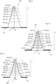
- Fig. 5 shows schematically in a sectioned side view an embodiment of a sealing mat 100 with several webs 120 Fig. 8.
- Fig. 1 shows schematically in a sectioned side view an embodiment of a sealing mat 100 with several webs 120.
- Fig. 2 shows schematically in a sectioned side view another embodiment of a sealing mat 100 with
- FIG. 6 shows schematically a detail B in a sectioned side view Fig. 5 .
- Fig. 7 shows schematically a detail C in a sectioned side view Fig. 6.
- Fig. 8 shows a schematic plan view of an embodiment of a sealing mat 100 with section line AA (see Fig. 5 ).
- Fig. 9 shows schematically in a side view an embodiment of a sealing mat 100 with several webs 120 arranged continuously in the axial direction V.
- Fig. 10 shows schematically in a side view an embodiment of a sealing mat 100 with several webs 120 arranged discretely in the axial direction V.
- Fig. 11 shows schematically in a side view another embodiment of a sealing mat 100 with several webs 120 arranged discretely in the axial direction V.
- the sealing mat 100 is designed as a one-piece mat made of an elastic and/or swellable sealing material such as a silicone material, a rubber material or the like.
- the mat 100 has a base body 110.
- Sealing projections, sealing formations or sealing webs 120 protrude obliquely, here vertically, from a top side 111 of the base body 110.
- the webs 120 are connected in one piece to the base body 110.
- the base body 110 has a constant material thickness s.
- the material thickness s is, for example, 2 mm.
- the base body 110 is designed as a flat circular disk or annular disk 113.
- the base body has a through opening 114 in the middle.
- the through opening 114 When used as a seal for a feedthrough, a pipe or the like is passed through the through opening 114.
- the through opening 114 can be changed according to the pipe to be passed through.
- the through opening 114 is cylindrical with a diameter D1.
- the area of the through opening is surrounded by a first web 121.
- the web 121 like the other webs 120, is designed as a concentric ring which runs around the center Z of the base body 110.
- the web 121 projects from the base body with a height H1 away.
- the height H1 is, for example, 25 mm.
- the webs 120 have a constant material thickness.
- the material thickness is preferably in the range of the material thickness of the base body, for example 2 mm.
- the inner diameter of the web 121 corresponds approximately to the diameter D1 of the through opening.
- the webs 120 protrude from the base body 110.
- the webs 120 are spaced partially radially differently from one another and/or from a central axis M running through a center Z and which is aligned perpendicular to the base body 110.
- the webs 120 are spaced apart so that their distance corresponds to the diameter of the various pipes 11 to be passed through.
- the webs 120 can, as in Fig. 1 to 8 shown, be spaced radially from the central axis M in a plane of the base body 110. In another embodiment, the webs 120 are spaced radially differently from the central axis M in the axial direction V.
- a second web 122 designed as a concentric point for the exemplary embodiment Fig. 1 to 8 an inner diameter D2, which is, for example, in the range of 63 mm.
- a third web 123 designed as a concentric has an inner diameter D3, which is, for example, in the range of 75 mm.
- a fourth web 124 designed as a concentric has an inner diameter D4, which is, for example, in the range of 90 mm.
- a fifth web 125 designed as a concentric has an inner diameter D5, which is, for example, in the range of 110 mm.
- a concentrically designed sixth web 126 has an inner diameter D6, which is, for example, in the range of 125 mm.
- the webs 120 are arranged at a distance from the outer edge of the base body 110, so that the base body 110 has a projection A relative to the outermost webs 120.
- the projection A is, for example, 30 mm, measured from an outer wall of the outermost web 120.
- the diameter of the base body Da is, for example, 189 mm.
- the total height H of the sealing mat 100, measured from an underside 112 of the base body 110 to the upper end of the longest web 120, is then, for example, 27 mm.
- Notches 130 are provided on the underside of the base body 110.
- the notches 130 are each provided adjacent to a continuation of the corresponding web 120, more precisely its inner wall 129.
- the notches are slightly offset inwards towards the center Z of the corresponding inner wall 129.
- the material of the sealing mat is designed to be cuttable.
- the base body 110 is cut along the web 120, which corresponds to the desired diameter or dimension of the pipe 11.
- the sealing mat 100 is shown, which is adapted for a pipe 11, the diameter of which corresponds to the fifth web from the outside (diameter approximately 63 mm).
- the base body 110 is severed along the corresponding wall.
- the through opening 114 has a diameter corresponding to the tube 11. The part of the base body 110 with webs 120 closer to the center Z is no longer present.
- the embodiment shown also has webs 120 that have different heights.
- the innermost web 122 has a height H2, which is approximately the height H1 from the exemplary embodiment Fig. 1 corresponds.
- the heights of the remaining webs 120 are shorter. Originally, the heights of the remaining webs 120 were the same as the height H2 of the innermost web 122. However, the outer webs 120 were shortened for improved handling.
- the webs 120 are also designed to be cuttable.
- a tube 11 protrudes through a through opening 114 through the sealing mat 100, more precisely the base body 110.
- the tube 11 has approximately an outside diameter that corresponds to the inside diameter of the adjacent web 120.
- the inner wall of the web 122 adjacent to the tube 10 lies against the tube 10 and thus seals it.
- the sealing effect can be increased by providing clamping means 150.
- Fig. 4 shows the embodiment Fig. 4 with additional clamping means 150.
- the clamping means 150 is in the Fig. 4 as a mounted clamping ring 151, for example designed as a hose clamp, plastic clamping ring or similar.
- Fig. 5 shows the sealing mat 100 in its original form Fig. 1 along a section line AA (see Fig. 8 ).
- the area for the is shown Fig. 6 , which shows the circled area B in detail.
- Fig. 6 shows the detailed view B.
- the arrangement of the respective notch 130 is shown in relation to the corresponding web 120.
- a notch 130 is formed on the underside 112 of the base body 110, in continuation of its inner wall 129.
- the respective notch 130 is arranged slightly offset from the continuation of the inner wall 129 by an offset v.
- the exact design of the respective notch 130 is shown in detail C Fig. 7 more clearly visible.
- Fig. 7 shows in detail the design of the notch 130.
- the notch 130 is tapered in section from the bottom 112 towards the top 111.
- the notch 130 is approximately triangular in cross section.
- the offset v from the continuation of the inner wall 129 is, for example, 1 mm.
- a width 132 of the notch 130 is, for example, 0.5 mm at the widest point.
- a depth 131 of the notch 130 is, for example, 0.5 mm.
- Fig. 8 the sealing mat 100 can be seen in the original state, that is, before parts of the sealing mat 100 are cut off, in a top view.
- the design of the webs 120 as concentric rings around the center Z is clearly shown here.
- Fig. 9 to 11 show three exemplary embodiments of a sealing mat 100, in which the webs 120 are not arranged directly on the base body 110 in the plane of the base body 110, but are arranged in the axial direction V web 120 on web 120 radially spaced from the axial central axis M.
- a first web 121 initially protrudes transversely from the base body 110.
- a web 122 which tapers or tapers at a radial distance from the central axis M then adjoins the first web 121.
- the adjacent web 120 in turn has a smaller radial distance from the central axis M.
- the webs 120 are arranged continuously adjacent to one another.
- the bridges protrude 120 transversely to the base body 110, with an angle of less than 90 degrees and greater than 75 degrees, so that in the axial direction V away from the base body 110, the radial distance to the central axis M decreases.
- the webs 120 protrude from the base body 110 at a right angle.
- intermediate sections 140 are provided between the individual webs 120.
- the intermediate sections 140 run in the in Fig. 10 illustrated embodiment perpendicular to the respective webs 120.
- the intermediate sections 140 run obliquely from one web 120 to the adjacent web 120, so that the adjacent webs 120 not only have a different radial distance from the central axis M, but also have an offset in the axial direction V.
- the respective web 120 is therefore not in contact with its entire length with its inside against a pipe 11 that is passed through, but only with a section that is shorter in the axial direction V.
- the corresponding sections are shown with the respective arrows.
- various dimensions for the outside diameter of pipes 11 to be passed through are shown.
- the dashed lines each represent an imaginary boundary between two adjacent webs 120.
- FIG. 10 and 11 also show the different pipe diameters Fig. 9 as an example.
- the radial distance of the webs 120 from the central axis M corresponds to the corresponding outer pipe diameter (or half of the pipe outer diameter).
- the entire inside of the respective web 120 lies against an outside of the pipe 11 that is passed through.
- the adjacent webs are axially spaced apart from one another by an offset.
- An axial length of a web 120 (8 mm) and an axial length of an offset (2 mm) are given as examples.
Landscapes
- Engineering & Computer Science (AREA)
- General Engineering & Computer Science (AREA)
- Mechanical Engineering (AREA)
- Gasket Seals (AREA)
Applications Claiming Priority (1)
| Application Number | Priority Date | Filing Date | Title |
|---|---|---|---|
| DE102022118323.8A DE102022118323B3 (de) | 2022-07-21 | 2022-07-21 | Abdichtungsmatte, abgedichtete Rohrdurchführung und Verfahren zurAbdichtung einer Durchführung |
Publications (1)
| Publication Number | Publication Date |
|---|---|
| EP4310377A1 true EP4310377A1 (fr) | 2024-01-24 |
Family
ID=87557696
Family Applications (1)
| Application Number | Title | Priority Date | Filing Date |
|---|---|---|---|
| EP23401020.5A Pending EP4310377A1 (fr) | 2022-07-21 | 2023-07-10 | Joint de peigne et procédé associé |
Country Status (2)
| Country | Link |
|---|---|
| EP (1) | EP4310377A1 (fr) |
| DE (1) | DE102022118323B3 (fr) |
Citations (7)
| Publication number | Priority date | Publication date | Assignee | Title |
|---|---|---|---|---|
| US4581824A (en) * | 1984-05-11 | 1986-04-15 | Psi Telecommunications | Portable adjustable washer cutter and improved washer |
| GB2230062A (en) * | 1989-04-04 | 1990-10-10 | Timber Res Dev Ass | Sealing shroud |
| EP1074776A1 (fr) * | 1999-08-06 | 2001-02-07 | Bocchiotti Societa'per L'industria Elettrotecnica S.P.A. | Presse-étoupe pour câble et/ou tuyau |
| US9863557B2 (en) * | 2012-03-02 | 2018-01-09 | Lake Products Limited | Escutcheon |
| US20190086005A1 (en) * | 2016-03-02 | 2019-03-21 | Carrier Corporation | Fastening system for a pipe passing through a panel of an air handling unit, and air handling unit comprising such a system |
| EP3299690B1 (fr) * | 2016-09-23 | 2019-10-23 | Trelleborg Industrial Products Finland OY | Disque d'étanchéité |
| EP3220030B1 (fr) * | 2016-03-15 | 2020-08-12 | DOYMA GmbH & Co | Élément d'étanchéité d'une conduite par rapport à une ouverture |
Family Cites Families (3)
| Publication number | Priority date | Publication date | Assignee | Title |
|---|---|---|---|---|
| JP2004317121A (ja) | 2004-08-18 | 2004-11-11 | Noritz Corp | 換気アダプタ並びにこの換気アダプタを用いた換気ファンユニット及び換気穴に対する換気パイプのシール構造 |
| DE102009056043A1 (de) | 2009-11-27 | 2011-06-01 | GM Global Technology Operations LLC, ( n. d. Ges. d. Staates Delaware ), Detroit | Dichtungsanordnung für die Kraftfahrzeugstirnwand |
| EP3266083B1 (fr) | 2015-03-03 | 2020-08-26 | LEONI Bordnetz-Systeme GmbH | Manchon d'étanchéité et passage de câble comprenant un manchon d'étanchéité |
-
2022
- 2022-07-21 DE DE102022118323.8A patent/DE102022118323B3/de active Active
-
2023
- 2023-07-10 EP EP23401020.5A patent/EP4310377A1/fr active Pending
Patent Citations (7)
| Publication number | Priority date | Publication date | Assignee | Title |
|---|---|---|---|---|
| US4581824A (en) * | 1984-05-11 | 1986-04-15 | Psi Telecommunications | Portable adjustable washer cutter and improved washer |
| GB2230062A (en) * | 1989-04-04 | 1990-10-10 | Timber Res Dev Ass | Sealing shroud |
| EP1074776A1 (fr) * | 1999-08-06 | 2001-02-07 | Bocchiotti Societa'per L'industria Elettrotecnica S.P.A. | Presse-étoupe pour câble et/ou tuyau |
| US9863557B2 (en) * | 2012-03-02 | 2018-01-09 | Lake Products Limited | Escutcheon |
| US20190086005A1 (en) * | 2016-03-02 | 2019-03-21 | Carrier Corporation | Fastening system for a pipe passing through a panel of an air handling unit, and air handling unit comprising such a system |
| EP3220030B1 (fr) * | 2016-03-15 | 2020-08-12 | DOYMA GmbH & Co | Élément d'étanchéité d'une conduite par rapport à une ouverture |
| EP3299690B1 (fr) * | 2016-09-23 | 2019-10-23 | Trelleborg Industrial Products Finland OY | Disque d'étanchéité |
Also Published As
| Publication number | Publication date |
|---|---|
| DE102022118323B3 (de) | 2023-11-23 |
Similar Documents
| Publication | Publication Date | Title |
|---|---|---|
| DE102005044317A1 (de) | Dichtungsmulden-Dichtungs-Kombination | |
| DE102004005381A1 (de) | Behälteranordnung und Verfahren zur Herstellung dieser Anordnung | |
| DE102014226679A1 (de) | Abdämmvorrichtung für Kabeldichtung | |
| DE69836553T2 (de) | Kuppelstück für rohre | |
| DE2556675A1 (de) | Vorrichtung zur befestigung eines kreisfoermigen scheibenfoermigen teils innerhalb eines zylindrischen teils | |
| DE102011050983A1 (de) | Verschlussstopfen für pharmazeutische Anwendungen | |
| DE3918891C2 (fr) | ||
| EP4310377A1 (fr) | Joint de peigne et procédé associé | |
| DE3521178A1 (de) | Druckdichtes kupplungsstueck fuer ein rohr | |
| DE2216678A1 (de) | Verbindungsstueck aus elastischem kunststoff | |
| EP2817549B1 (fr) | Raccord d'assemblage de pièces cylindriques | |
| WO2002070939A1 (fr) | Manchon d'etancheite | |
| DE102016219889B4 (de) | Dichtring | |
| EP3255330B1 (fr) | Utilisation d'une douille d'etancheite | |
| DE2612240A1 (de) | Rohrverbindungseinrichtung | |
| DE102014102260B4 (de) | Baukasten für die Abdichtung des Durchganges von Kabeln oder Adern, die durch eine Platte verlaufen sowie Verfahren zum Abdichten | |
| DE102015122766A1 (de) | "Zahnscheibe mit mehrstegigen Haltezähnen" | |
| DE102019115162A1 (de) | Vorrichtung für den Stoff- und/oder Energieaustausch zwischen zwei Medien und Verfahren zu dessen Herstellung | |
| DE102016005487B4 (de) | Montageeinrichtung zum Montieren einer Armatur | |
| DE2640037A1 (de) | Verbindungsdichtung fuer zwei gehaeuseteile | |
| DE102022107221B4 (de) | Verwendung eines Durchführungssystems | |
| EP2988045B1 (fr) | Joint de branchement domestique, en particulier un branchement domestique multi-voies | |
| DE4217154A1 (de) | Radialdichtungsanordnung | |
| AT237393B (de) | Rohrverbindung | |
| DE102021127094A1 (de) | Bauteil aus Kunststoff mit integrierter Dichtanordnung |
Legal Events
| Date | Code | Title | Description |
|---|---|---|---|
| PUAI | Public reference made under article 153(3) epc to a published international application that has entered the european phase |
Free format text: ORIGINAL CODE: 0009012 |
|
| STAA | Information on the status of an ep patent application or granted ep patent |
Free format text: STATUS: THE APPLICATION HAS BEEN PUBLISHED |
|
| AK | Designated contracting states |
Kind code of ref document: A1 Designated state(s): AL AT BE BG CH CY CZ DE DK EE ES FI FR GB GR HR HU IE IS IT LI LT LU LV MC ME MK MT NL NO PL PT RO RS SE SI SK SM TR |