EP4310377A1 - Comb seal and method therefor - Google Patents
Comb seal and method therefor Download PDFInfo
- Publication number
- EP4310377A1 EP4310377A1 EP23401020.5A EP23401020A EP4310377A1 EP 4310377 A1 EP4310377 A1 EP 4310377A1 EP 23401020 A EP23401020 A EP 23401020A EP 4310377 A1 EP4310377 A1 EP 4310377A1
- Authority
- EP
- European Patent Office
- Prior art keywords
- sealing
- webs
- base body
- pipe
- mat
- Prior art date
- Legal status (The legal status is an assumption and is not a legal conclusion. Google has not performed a legal analysis and makes no representation as to the accuracy of the status listed.)
- Pending
Links
- 238000000034 method Methods 0.000 title claims abstract description 15
- 238000007789 sealing Methods 0.000 claims abstract description 238
- 239000000463 material Substances 0.000 claims description 48
- 230000007704 transition Effects 0.000 description 12
- 229920001971 elastomer Polymers 0.000 description 9
- 230000008961 swelling Effects 0.000 description 9
- 238000005520 cutting process Methods 0.000 description 8
- 238000004519 manufacturing process Methods 0.000 description 7
- 230000035515 penetration Effects 0.000 description 7
- 229920002725 thermoplastic elastomer Polymers 0.000 description 7
- 239000000806 elastomer Substances 0.000 description 6
- 239000007788 liquid Substances 0.000 description 6
- 230000006835 compression Effects 0.000 description 5
- 238000007906 compression Methods 0.000 description 5
- 239000004033 plastic Substances 0.000 description 4
- 229920003023 plastic Polymers 0.000 description 4
- 239000000853 adhesive Substances 0.000 description 3
- 230000001070 adhesive effect Effects 0.000 description 3
- 230000005484 gravity Effects 0.000 description 3
- 238000001746 injection moulding Methods 0.000 description 3
- 229920001169 thermoplastic Polymers 0.000 description 3
- 229920001187 thermosetting polymer Polymers 0.000 description 3
- 239000004416 thermosoftening plastic Substances 0.000 description 3
- XLYOFNOQVPJJNP-UHFFFAOYSA-N water Substances O XLYOFNOQVPJJNP-UHFFFAOYSA-N 0.000 description 3
- 238000010521 absorption reaction Methods 0.000 description 2
- 239000000654 additive Substances 0.000 description 2
- 230000004323 axial length Effects 0.000 description 2
- 230000006378 damage Effects 0.000 description 2
- 230000007423 decrease Effects 0.000 description 2
- 238000001125 extrusion Methods 0.000 description 2
- 238000000465 moulding Methods 0.000 description 2
- 229920001296 polysiloxane Polymers 0.000 description 2
- 238000003825 pressing Methods 0.000 description 2
- 238000004080 punching Methods 0.000 description 2
- 239000003566 sealing material Substances 0.000 description 2
- 238000004026 adhesive bonding Methods 0.000 description 1
- 229910000278 bentonite Inorganic materials 0.000 description 1
- 239000000440 bentonite Substances 0.000 description 1
- SVPXDRXYRYOSEX-UHFFFAOYSA-N bentoquatam Chemical compound O.O=[Si]=O.O=[Al]O[Al]=O SVPXDRXYRYOSEX-UHFFFAOYSA-N 0.000 description 1
- 230000015572 biosynthetic process Effects 0.000 description 1
- 238000005266 casting Methods 0.000 description 1
- 239000002131 composite material Substances 0.000 description 1
- 150000001875 compounds Chemical class 0.000 description 1
- 230000000694 effects Effects 0.000 description 1
- 239000013013 elastic material Substances 0.000 description 1
- 238000005755 formation reaction Methods 0.000 description 1
- 239000012528 membrane Substances 0.000 description 1
- 229920000058 polyacrylate Polymers 0.000 description 1
- 239000006228 supernatant Substances 0.000 description 1
- 230000002522 swelling effect Effects 0.000 description 1
- 238000004078 waterproofing Methods 0.000 description 1
Images


Classifications
-
- F—MECHANICAL ENGINEERING; LIGHTING; HEATING; WEAPONS; BLASTING
- F16—ENGINEERING ELEMENTS AND UNITS; GENERAL MEASURES FOR PRODUCING AND MAINTAINING EFFECTIVE FUNCTIONING OF MACHINES OR INSTALLATIONS; THERMAL INSULATION IN GENERAL
- F16L—PIPES; JOINTS OR FITTINGS FOR PIPES; SUPPORTS FOR PIPES, CABLES OR PROTECTIVE TUBING; MEANS FOR THERMAL INSULATION IN GENERAL
- F16L5/00—Devices for use where pipes, cables or protective tubing pass through walls or partitions
- F16L5/02—Sealing
- F16L5/10—Sealing by using sealing rings or sleeves only
-
- E—FIXED CONSTRUCTIONS
- E04—BUILDING
- E04G—SCAFFOLDING; FORMS; SHUTTERING; BUILDING IMPLEMENTS OR AIDS, OR THEIR USE; HANDLING BUILDING MATERIALS ON THE SITE; REPAIRING, BREAKING-UP OR OTHER WORK ON EXISTING BUILDINGS
- E04G15/00—Forms or shutterings for making openings, cavities, slits, or channels
- E04G15/06—Forms or shutterings for making openings, cavities, slits, or channels for cavities or channels in walls of floors, e.g. for making chimneys
- E04G15/061—Non-reusable forms
Definitions
- the invention relates to a sealing mat for sealing a bushing, in particular for sealing a pipe bushing according to claim 1.
- the invention also relates to a sealed pipe bushing, comprising a pipe and a sealing mat according to claim 7.
- the invention relates to a method for sealing a bushing, in particular for sealing a pipe bushing according to claim 9.
- Pipe seals, sealing rings, etc. are generally known from the prior art.
- the known seals are designed for a specific pipe diameter.
- the invention includes the technical teaching that in a sealing mat for sealing a bushing, in particular for sealing a pipe bushing, comprising a flat base body which extends over a base plane, with an upper side and a lower side, it is provided that at least one of the Sealing projections or sealing webs protrude transversely to the base plane on both sides, the sealing projections or sealing webs being spaced radially differently from a center line projecting vertically through a center of the base plane or the base body or the sealing mat, so that a bushing can be sealingly received between the sealing projections or sealing webs.
- a center of the base level is in particular the center of an area intended for a feedthrough, thus a later recess.
- the sealing mat is intended for sealing pipe penetrations with different external dimensions such as outer diameter or outer circumference.
- the pipe bushings can have different shapes in the cross-sectional direction.
- the pipe bushing can be designed to be rotationally symmetrical (ring-shaped or circular) or not rotationally symmetrical (oval, square, rectangular, polygonal), at least with respect to its outer contour.
- the base body has an area for a through opening, a through opening or a prepared through opening through which a pipe can be passed.
- Means can be provided to simplify the production of the through opening, for example in the form of cutting or punching aids. Such means may include grooves, depressions, perforations, markings, projections and the like. Only through openings or recesses are listed below, whereby, unless expressly stated otherwise, prepared through openings or recesses or areas for through openings may also be included.
- a through opening can be subsequently produced in a simple manner.
- Different means for producing through openings are provided for passage openings of different sizes. These means for producing through openings can be produced early in the manufacturing process of the sealing mat, i.e. before the dimensions of the pipe bushing to be sealed are known.
- the through opening itself - i.e. without means - can only be produced after the dimensions of the through opening are known.
- the sealing mat is preferably intended for hollow cylindrical pipes, so that the through opening preferably has a circular cross section.
- the through opening is preferably arranged centrally.
- the contour of the Through opening corresponds to the outer contour of the pipe to be accommodated.
- the flat base body is preferably designed like a disk or mat and can have any desired (cross-sectional) shape in a top view. Accordingly, the base body has a significantly smaller dimension in one spatial direction than in the other two spatial directions. Preferably, the dimension is designed to be constant in the direction of the spatial direction with the smallest dimension, i.e. in the direction of the base body thickness. In other embodiments, the base body thickness is variable or designed differently.
- the material of the base body is preferably an elastic material which is suitable for sealing, in particular sealing against water.
- the base body is made of a building-sealing material.
- the base body material is a material that is suitable for penetrations or pipe bushings.
- These can be suitable plastic, rubber, silicone and/or swellable materials.
- the materials may generally be swellable materials and/or non-swellable materials. In principle, all materials that can be processed into shapes are used as materials.
- Preferably, partially cross-linked and/or completely cross-linked elastomer materials or thermoelastic elastomers (TPE) are used, which are made swellable by organic or inorganic additives.
- Swellable additives here are preferably partially neutralized polyacrylate and/or bentonite.
- materials from the classes of elastomers, thermoplastics, thermoplastic elastomers and thermosets are preferred for the sealing mat and/or the sealing webs or sealing projections, preferably materials from the class of thermoplastic elastomers.
- the production of the projections or webs, which function as a sealing ring during sealing can be carried out using methods of rubber and/or thermoplastic and/or thermoset processing, for example by means of extrusion, injection molding, pressing, etc. Preferably the production takes place by means of injection molding.
- the material for the sealing mat and/or for the sealing webs or sealing projections has a suitable hardness, in particular a Shore hardness.
- DIN ISO 7619-1 Elastomers or thermoplastic elastomers - Determination of penetration hardness - Part 1: Durometer method (Shore hardness) is used to determine, define and characterize Shore hardness.
- the Shore hardness of the seal is preferably in the range 20 to 85 Shore A, more preferably in the range 40 to 70 Shore A.
- the material for the sealing mat and/or the sealing webs or sealing projections - or sealing rings - has a suitable elongation or elasticity.
- the elongations at break of the materials are preferably in the range from 50 to 800%, more preferably in the range from 150 to 450%.
- the materials for the sealing mat and/or sealing projections or sealing webs have a suitable compression set.
- the compression set is preferably in the range of 0 to 95% (24 h, 23 °C), more preferably in the range of 0 to 40% (24 h, 23 °C).
- the materials for the sealing mat and/or sealing projections or sealing webs have suitable swelling properties.
- the material for the seal (base body, webs, projections, sealing rings) includes or consists of a swellable material. If a leak occurs, liquid (e.g. water from the ground) reaches the seal. This swells as liquid is stored, thereby increasing its volume and sealing the resulting leak securely, independently and permanently off again.
- the method of liquid absorption with free swelling (Free Swelling Capacity - FSC value) is used to determine, define and characterize the swelling. With this method, a material sample is placed in liquid and can swell without restricting the swelling process. The relative increase in mass of the material sample is determined as a function of time.
- the relative mass increase is defined as the liquid mass absorbed based on the dry sample mass and is given in percent. A relative liquid absorption of 100% corresponds to a doubling of the dry sample mass.
- the seal has relative mass increases, in swelling equilibrium, of preferably 10 to 800%, more preferably relative mass increases of 50 to 125%. The swelling equilibrium is preferably reached after 5 to 500 hours, more preferably the swelling equilibrium is reached after 10 to 72 hours.
- the material from which the sealing mat and/or the sealing projections and/or sealing webs is made is selected from the group comprising elastomers, thermoplastics, thermoplastic elastomers and thermosets. Materials from the class of thermoplastic elastomers are preferably used.
- the base body has a top and an opposite bottom.
- sealing webs or sealing projections - hereinafter referred to as webs - protrude transversely from the base body.
- the webs can project at any angle transversely from the base body, more precisely one side of the base body, for example the top.
- the webs preferably protrude essentially at right angles or at an angle of greater than 60 degrees, preferably greater than 70 degrees and most preferably greater than 80 degrees and/or less than 120 degrees, preferably less than 110 degrees and most preferably less than 100 degrees from the corresponding side .
- the plurality of sealing webs can be connected to one another and arranged adjacent to one another in the axial direction of the imaginary center line through the center.
- the sealing webs can also be designed to be radially spaced apart from one another in the direction of the main extension of the base body, thus at right angles to the imaginary center line.
- the individual webs do not contact each other, but only contact the base body.
- a combination of webs that are adjacent to one another and do not contact one another is also provided in one embodiment.
- the webs are designed as webs or web rings that are spaced apart from one another and protrude from one side of the base body.
- the webs are designed as adjacent or adjacent webs or web rings. In the embodiment in which the webs do not contact each other, a radial distance is provided between the webs.
- the webs are arranged horizontally on one level - the base body.
- the webs have a radial offset from one another and are arranged at different axial distances from the base body. A transition section or intermediate section can be provided between adjacent webs.
- the sealing webs form a polygonal shape, at least in a side or cross-sectional view.
- a sealing web with a first radial distance from the center line adjoins another sealing web that adjoins it with a different radial distance.
- the next sealing web again with a different radial distance, adjoins the previous sealing web, so that a kind of polygon, pyramid or cone shape results in the axial direction of the center line.
- the transitions of the sealing webs can be continuous or abrupt. In the case of a continuous transition, the radial distances between the sealing webs are also designed to change continuously. A crack-free lateral surface or outside is created.
- intermediate sections or transition sections are provided between the sealing webs or, more precisely, sealing sections.
- the transition section opens into the other sealing webs at an angle.
- the angle can be a right angle.
- a different angle is provided.
- a subsequent sealing web also protrudes at an angle from the transition section. This allows at least two sealing webs, in one embodiment all of them Sealing webs can be designed perpendicular to the base body, while the transition sections between two adjacent sealing webs are arranged at an angle not equal to or equal to 90 degrees to the base body. In a continuous embodiment, the webs are arranged at an angle not equal to 90° to the base body and protrude from the base body as inclined to it.
- sealing web rests on a pipe that is passed through and is guided vertically through the base body.
- sealing webs projecting at 90° at least almost the entire sealing web rests on the inside of the pipe through which it is inserted. If a transition section is provided, it does not rest on the pipe being passed through.
- the sealing webs When the sealing webs are lined up axially, the sealing web that projects directly from the base body has the greatest radial distance from the center line through the center.
- the sealing webs and/or transition sections adjoining it in the axial direction have radial distances from the center line that become smaller or taper as the axial distance from the base body increases.
- the sealing webs themselves are of the same length in the direction of projection and therefore have the same length in the direction of extension and/or transversely to the direction of extension.
- at least two webs are of different lengths in the direction of extension and/or dimensioned transversely to the direction of extension.
- all webs can also be dimensioned differently in the direction of extension and/or transversely to the direction of extension.
- the direction of extension is preferably the axial direction (the center line).
- the webs have a material thickness. In one embodiment, this is designed to be constant along the direction of extension. In other embodiments, the material thickness can vary along the direction of extension, for example, it can taper. In one embodiment, all webs have the same material thickness and/or the same material thickness progression along the direction of extension. In other embodiments, the material thickness varies along the direction of extension between at least two webs. In one embodiment, the webs for demolding in a manufacturing process such as injection molding, a suitable shape, for example a taper in the direction away from the base body. This taper provided for demolding can be provided both for webs with otherwise constant material thickness and for webs with at least partially varying material thickness.
- the webs are at least radially spaced apart from one another - horizontally or in the plane of the base body or vertically or axially in the case of existing transition sections. At least the webs are at a different distance radially from the central axis. In one embodiment, the webs are spaced radially equidistant from one another and/or from the central axis. In another embodiment, the webs are spaced radially differently from one another and/or from the central axis. Preferably, at least two of the webs are spaced differently radially from one another and/or radially from a central axis.
- the distance between the webs or sections of the webs radially from one another and/or from the central axis is at least such that a tube can be accommodated between the webs.
- This means that the radial distance between two adjacent webs and/or to the central axis is at least as large as the wall thickness of a pipe to be accommodated. In the case of a continuous axial alignment, this applies to sections of the respective sealing web.
- sealing projections or sealing webs are separately connected to the base body via corresponding connecting means.
- sealing projections or sealing webs and the base body are at least partially formed in one piece or at least partially in multiple parts with one another.
- a one-piece embodiment of the sealing mat is preferred.
- the sealing projections or sealing webs and the base body are formed in one piece with one another. In another embodiment, the sealing projections or sealing webs and the base body are formed in several parts together. In yet another embodiment, the sealing projections or sealing webs and the base body are at least partially formed in one piece and at least partially in multiple parts with one another.
- the web material corresponds to the base body material in a one-piece design with the base body.
- the materials for webs or projections and base body can be at least partially the same or at least partially different.
- the projections or webs can be connected to the base body in a detachable manner - non-destructively or with at least partial destruction - or non-detachably, that is to say only with destruction of at least parts of the base body and the web or the projection.
- the connection can be any.
- the connection is made in a cohesive manner, for example by gluing.
- the connection is designed to be form-fitting.
- the connection is designed to be non-positive. Combinations of this are also possible.
- additional webs or projections can be subsequently attached to or detached from the base body.
- the base body is designed in a disk-like or mat-like manner, for example as a web material.
- the disk-like base body is preferably designed as a circular disk with a circular cross section when viewed from above. Other shapes such as rectangles, polygons, ovals and the like are also possible.
- the sealing projections or the sealing webs are formed circumferentially around a center of the base body, so that in a plan view they are formed like a ring and/or as concentric rings.
- the center of the base body is preferably the center of the area for the recess or passage or the center or center of gravity of the area for the passage.
- the central axis is congruent with the central axis of the pipe.
- the webs are designed in other shapes all around. If the webs are designed all around in a horizontal orientation, the webs only have an upper wall and two side walls. The webs form a closed shape, preferably as a circular ring.
- the webs can also be designed as non-circumferential webs, thus as web sections. These then point next to the three Walls listed above have two further end walls. Circumferential webs are preferred for sealing pipe penetrations.
- the webs preferably run around a center of the base body or the center of the passage of the recess for the pipe passage. For a circular disk, this corresponds to the center of the disk. In other embodiments, this may generally be the center of gravity or the center of the area.
- the center preferably forms the center or imaginary center of gravity of the recess, through which the imaginary axial center line runs, which in the case of a pipe feedthrough then also lies on the central axis of the pipe.
- a through opening is provided between the webs, preferably in or around a center or around a center point.
- a pipe can be passed through the through opening.
- the through opening borders on a web or an imaginary continuation of the web. In this way, the sealing mat creates a seal for a pipe bushing.
- Yet another embodiment provides that on a side opposite the side with the projecting sealing projections or sealing webs and/or and/or the inside and/or outside of the sealing projections or webs and/or on those of the transition sections, aids for producing a through opening or Recesses such as notches, material thinnings and/or recesses are provided.
- the base body preferably has webs on only one side, for example on the top. Accordingly, the aids or aids for producing a through opening, such as notches, material thinnings and / or recesses on the underside in an embodiment in which the webs protrude directly from the base body and / or on the inside and / or outside of the webs an axial alignment of the webs is provided.
- the aids are arranged offset from the continuation of the webs towards the underside and/or inside and/or outside.
- the aids preferably run offset to an inner wall of the webs.
- the inner wall or inner wall of the webs is the wall that faces the center of the base body.
- the aids are preferably rotating Aids trained. This means that the aids run at equal distances from the continuation of the webs.
- the aids are each arranged closer to the inner wall of a web than to the outer wall of the adjacent web.
- the outer wall of a web is opposite the inner wall.
- the aids can also be formed on the transition sections, in particular with an axial alignment of the webs.
- the shape of the aids such as notches, material thinning, recesses can be arbitrary.
- the respective aid is preferably designed to taper in cross section in the direction of the web.
- the width of the respective aid is smaller than the distance to the continuation of the inner wall of the web, preferably approximately half as large.
- the aids also include perforations or the like.
- the invention also includes the technical teaching that in the case of a sealed pipe bushing, comprising a pipe and a sealing mat, it is provided that the sealing mat is designed according to one of the preceding claims, wherein the base body of the sealing mat forms a recess or through opening along a recess or through opening for the passage of the pipe one of the sealing projections or sealing webs, and the tube penetrates the base body laterally adjacent to a sealing projection or a sealing web.
- the sealing mat has a recess or through opening for the passage. This is created by producing the through opening, for example by cutting it out, along a circumferential sealing web. The through-opening is produced, for example by cutting, adjacent to an inner wall or inside of the sealing web.
- the webs are preferably designed in such a way that they are adapted to specific pipe diameters. Depending on the outside diameter of the pipe, the cutting takes place along the sealing web, which corresponds to the outside diameter of the pipe.
- the recess/through opening is adapted to the contour of the pipe. In particular, the recess/through opening is circular.
- the sealing mat is fixed to the pipe.
- the sealing projection or sealing web adjacent to the pipe being passed through is clamped to the pipe by means of a clamping means.
- other fixing means are provided.
- the sealing mat can be glued to the pipe, preferably with the sealing web.
- the sealing web is fixed against the pipe, for example clamped, glued or otherwise fixed.
- clamping rings, hose clamps, plastic clamping rings or the like are provided as clamping means.
- Adhesives or the like are provided as adhesives.
- fixation using magnetic means is also provided.
- the sealing webs can also have positive locking means that correspond to a positive locking means of the pipe.
- the sealing mat is designed to be cast in concrete.
- the sealing mat is intended as a fresh concrete composite sealing membrane.
- the sealing mat is used in particular to create sealed pipe penetrations through concrete. Casting it in concrete also fixes the sealing mat.
- the invention further includes the technical teaching that in a method for sealing a bushing, in particular for sealing a pipe bushing, the following steps are provided: providing a sealing mat described here, providing a recess or through opening along a sealing projection or sealing web, in order to create a passage for the pipe passage, passing a pipe through the recess or the passage or the through opening, the pipe with its outer wall adjoining the sealing projection or the sealing web along which the recess/through opening is formed, so that the pipe is separated from the corresponding Sealing projection or sealing web is sealed.
- a recess or pipe bushing can be done before or after the sealing mat is provided.
- a sealing mat is provided without a recess or through-opening and the recess or through-opening is only manufactured or provided after it has been provided.
- the manufacturing or provision can be realized using any method.
- the recess or the through opening can be realized by cutting out, punching out, pressing out or in any other way.
- the sealing mat can be prepared accordingly, for example by providing a cutting aid, perforations or the like.
- the recess or through opening is provided in the immediate vicinity of the sealing web or sealing projection.
- a distance can be provided in the plane of the sealing mat between the recess or through opening and the sealing web or sealing projection.
- the distance, in particular the radial distance, between the recess or through opening and the web or projection is preferably in a range from 0 mm to 20 mm, more preferably from 1 mm to 15 mm and most preferably from 2 mm to 10 mm.
- the sealing mat is fixed.
- the waterproofing mat can be fixed in various ways.
- the sealing projection or the sealing web, which adjoins the outer wall of the pipe passed through, can be clamped against the outer wall of the pipe with a clamping means.
- the sealing mat can be fixed.
- the sealing mat can be fixed using fixing means, for example with cohesive, non-positive and/or positive means.
- the sealing mat is glued using an adhesive.
- the sealing mat is cast in concrete.
- the sealing mat can be fixed in various places. The fixation can be fixed on the web, on the base body - both on the top and on the bottom - even in combination.
- a sealing mat described here is provided. It becomes the outside diameter of the pipe corresponding sealing web identified.
- the inside of the sealing web is adjacent to the outer wall of the pipe.
- a recess or through opening is created in the base body along the identified sealing web. This is preferably done by cutting out. In this way, the recess or through opening is created through which the pipe can be guided.
- the tube is inserted through the recess/through opening.
- the outer wall is guided along the inside of the adjacent sealing web.
- the inside of the sealing web preferably contacts the outer wall of the pipe. In this way a seal is achieved.
- the sealing web is clamped against the pipe. This makes it possible to achieve improved sealing for different pipe diameters.
- FIG. 1 to 11 show various exemplary embodiments of a sealing mat 100 according to the invention for a pipe bushing 10 in different views and different levels of detail.
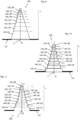
- Fig. 1 shows schematically in a sectioned side view an embodiment of a sealing mat 100 with several webs 120.
- Fig. 2 shows schematically in a sectioned side view another embodiment of a sealing mat 100 with several webs 100.
- Fig. 3 shows the embodiment schematically in a sectioned side view after Fig. 2 with a (pipe) bushing 10.
- Fig. 4 shows schematically the embodiment in a sectioned side view Fig. 3 with an additional clamping device 150.
- Fig. 5 shows schematically in a sectioned side view an embodiment of a sealing mat 100 with several webs 120 Fig. 8.
- Fig. 1 shows schematically in a sectioned side view an embodiment of a sealing mat 100 with several webs 120.
- Fig. 2 shows schematically in a sectioned side view another embodiment of a sealing mat 100 with
- FIG. 6 shows schematically a detail B in a sectioned side view Fig. 5 .
- Fig. 7 shows schematically a detail C in a sectioned side view Fig. 6.
- Fig. 8 shows a schematic plan view of an embodiment of a sealing mat 100 with section line AA (see Fig. 5 ).
- Fig. 9 shows schematically in a side view an embodiment of a sealing mat 100 with several webs 120 arranged continuously in the axial direction V.
- Fig. 10 shows schematically in a side view an embodiment of a sealing mat 100 with several webs 120 arranged discretely in the axial direction V.
- Fig. 11 shows schematically in a side view another embodiment of a sealing mat 100 with several webs 120 arranged discretely in the axial direction V.
- the sealing mat 100 is designed as a one-piece mat made of an elastic and/or swellable sealing material such as a silicone material, a rubber material or the like.
- the mat 100 has a base body 110.
- Sealing projections, sealing formations or sealing webs 120 protrude obliquely, here vertically, from a top side 111 of the base body 110.
- the webs 120 are connected in one piece to the base body 110.
- the base body 110 has a constant material thickness s.
- the material thickness s is, for example, 2 mm.
- the base body 110 is designed as a flat circular disk or annular disk 113.
- the base body has a through opening 114 in the middle.
- the through opening 114 When used as a seal for a feedthrough, a pipe or the like is passed through the through opening 114.
- the through opening 114 can be changed according to the pipe to be passed through.
- the through opening 114 is cylindrical with a diameter D1.
- the area of the through opening is surrounded by a first web 121.
- the web 121 like the other webs 120, is designed as a concentric ring which runs around the center Z of the base body 110.
- the web 121 projects from the base body with a height H1 away.
- the height H1 is, for example, 25 mm.
- the webs 120 have a constant material thickness.
- the material thickness is preferably in the range of the material thickness of the base body, for example 2 mm.
- the inner diameter of the web 121 corresponds approximately to the diameter D1 of the through opening.
- the webs 120 protrude from the base body 110.
- the webs 120 are spaced partially radially differently from one another and/or from a central axis M running through a center Z and which is aligned perpendicular to the base body 110.
- the webs 120 are spaced apart so that their distance corresponds to the diameter of the various pipes 11 to be passed through.
- the webs 120 can, as in Fig. 1 to 8 shown, be spaced radially from the central axis M in a plane of the base body 110. In another embodiment, the webs 120 are spaced radially differently from the central axis M in the axial direction V.
- a second web 122 designed as a concentric point for the exemplary embodiment Fig. 1 to 8 an inner diameter D2, which is, for example, in the range of 63 mm.
- a third web 123 designed as a concentric has an inner diameter D3, which is, for example, in the range of 75 mm.
- a fourth web 124 designed as a concentric has an inner diameter D4, which is, for example, in the range of 90 mm.
- a fifth web 125 designed as a concentric has an inner diameter D5, which is, for example, in the range of 110 mm.
- a concentrically designed sixth web 126 has an inner diameter D6, which is, for example, in the range of 125 mm.
- the webs 120 are arranged at a distance from the outer edge of the base body 110, so that the base body 110 has a projection A relative to the outermost webs 120.
- the projection A is, for example, 30 mm, measured from an outer wall of the outermost web 120.
- the diameter of the base body Da is, for example, 189 mm.
- the total height H of the sealing mat 100, measured from an underside 112 of the base body 110 to the upper end of the longest web 120, is then, for example, 27 mm.
- Notches 130 are provided on the underside of the base body 110.
- the notches 130 are each provided adjacent to a continuation of the corresponding web 120, more precisely its inner wall 129.
- the notches are slightly offset inwards towards the center Z of the corresponding inner wall 129.
- the material of the sealing mat is designed to be cuttable.
- the base body 110 is cut along the web 120, which corresponds to the desired diameter or dimension of the pipe 11.
- the sealing mat 100 is shown, which is adapted for a pipe 11, the diameter of which corresponds to the fifth web from the outside (diameter approximately 63 mm).
- the base body 110 is severed along the corresponding wall.
- the through opening 114 has a diameter corresponding to the tube 11. The part of the base body 110 with webs 120 closer to the center Z is no longer present.
- the embodiment shown also has webs 120 that have different heights.
- the innermost web 122 has a height H2, which is approximately the height H1 from the exemplary embodiment Fig. 1 corresponds.
- the heights of the remaining webs 120 are shorter. Originally, the heights of the remaining webs 120 were the same as the height H2 of the innermost web 122. However, the outer webs 120 were shortened for improved handling.
- the webs 120 are also designed to be cuttable.
- a tube 11 protrudes through a through opening 114 through the sealing mat 100, more precisely the base body 110.
- the tube 11 has approximately an outside diameter that corresponds to the inside diameter of the adjacent web 120.
- the inner wall of the web 122 adjacent to the tube 10 lies against the tube 10 and thus seals it.
- the sealing effect can be increased by providing clamping means 150.
- Fig. 4 shows the embodiment Fig. 4 with additional clamping means 150.
- the clamping means 150 is in the Fig. 4 as a mounted clamping ring 151, for example designed as a hose clamp, plastic clamping ring or similar.
- Fig. 5 shows the sealing mat 100 in its original form Fig. 1 along a section line AA (see Fig. 8 ).
- the area for the is shown Fig. 6 , which shows the circled area B in detail.
- Fig. 6 shows the detailed view B.
- the arrangement of the respective notch 130 is shown in relation to the corresponding web 120.
- a notch 130 is formed on the underside 112 of the base body 110, in continuation of its inner wall 129.
- the respective notch 130 is arranged slightly offset from the continuation of the inner wall 129 by an offset v.
- the exact design of the respective notch 130 is shown in detail C Fig. 7 more clearly visible.
- Fig. 7 shows in detail the design of the notch 130.
- the notch 130 is tapered in section from the bottom 112 towards the top 111.
- the notch 130 is approximately triangular in cross section.
- the offset v from the continuation of the inner wall 129 is, for example, 1 mm.
- a width 132 of the notch 130 is, for example, 0.5 mm at the widest point.
- a depth 131 of the notch 130 is, for example, 0.5 mm.
- Fig. 8 the sealing mat 100 can be seen in the original state, that is, before parts of the sealing mat 100 are cut off, in a top view.
- the design of the webs 120 as concentric rings around the center Z is clearly shown here.
- Fig. 9 to 11 show three exemplary embodiments of a sealing mat 100, in which the webs 120 are not arranged directly on the base body 110 in the plane of the base body 110, but are arranged in the axial direction V web 120 on web 120 radially spaced from the axial central axis M.
- a first web 121 initially protrudes transversely from the base body 110.
- a web 122 which tapers or tapers at a radial distance from the central axis M then adjoins the first web 121.
- the adjacent web 120 in turn has a smaller radial distance from the central axis M.
- the webs 120 are arranged continuously adjacent to one another.
- the bridges protrude 120 transversely to the base body 110, with an angle of less than 90 degrees and greater than 75 degrees, so that in the axial direction V away from the base body 110, the radial distance to the central axis M decreases.
- the webs 120 protrude from the base body 110 at a right angle.
- intermediate sections 140 are provided between the individual webs 120.
- the intermediate sections 140 run in the in Fig. 10 illustrated embodiment perpendicular to the respective webs 120.
- the intermediate sections 140 run obliquely from one web 120 to the adjacent web 120, so that the adjacent webs 120 not only have a different radial distance from the central axis M, but also have an offset in the axial direction V.
- the respective web 120 is therefore not in contact with its entire length with its inside against a pipe 11 that is passed through, but only with a section that is shorter in the axial direction V.
- the corresponding sections are shown with the respective arrows.
- various dimensions for the outside diameter of pipes 11 to be passed through are shown.
- the dashed lines each represent an imaginary boundary between two adjacent webs 120.
- FIG. 10 and 11 also show the different pipe diameters Fig. 9 as an example.
- the radial distance of the webs 120 from the central axis M corresponds to the corresponding outer pipe diameter (or half of the pipe outer diameter).
- the entire inside of the respective web 120 lies against an outside of the pipe 11 that is passed through.
- the adjacent webs are axially spaced apart from one another by an offset.
- An axial length of a web 120 (8 mm) and an axial length of an offset (2 mm) are given as examples.
Abstract
Der Gegenstand der vorliegenden Erfindung betrifft eine Abdichtungsmatte (100) zur Abdichtung einer Durchführung, insbesondere zur Abdichtung einer Rohrdurchführung (10), umfassend einen flächigen Basiskörper (110), der sich über eine Basisebene erstreckt, mit einer Oberseite (111) und einer Unterseite (112), wobei zumindest von einer der beiden Seiten quer zu der Basisebene rippenartig Dichtungsvorsprünge oder Dichtungsstege (120) abragen, wobei die Dichtungsvorsprünge oder Dichtungsstege (120) zu einer durch ein Zentrum (Z) der Basisebene senkrecht abragenden Mittellinie radial unterschiedlich beabstandet sind, sodass zwischen den Dichtungsvorsprüngen oder Dichtungsstegen (120) eine Durchführung (10) abdichtend aufnehmbar ist. Zudem betrifft die Erfindung ein Abdichtungsverfahren hierzu.

Description
Die Erfindung betrifft eine Abdichtungsmatte zur Abdichtung einer Durchführung, insbesondere zur Abdichtung einer Rohrdurchführung gemäß Anspruch 1.The invention relates to a sealing mat for sealing a bushing, in particular for sealing a pipe bushing according to
Auch betrifft die Erfindung eine abgedichtete Rohrdurchführung, umfassend ein Rohr und eine Abdichtungsmatte gemäß Anspruch 7.The invention also relates to a sealed pipe bushing, comprising a pipe and a sealing mat according to claim 7.
Nicht zuletzt betrifft die Erfindung ein Verfahren zur Abdichtung einer Durchführung, insbesondere zur Abdichtung einer Rohrdurchführung gemäß Anspruch 9.Last but not least, the invention relates to a method for sealing a bushing, in particular for sealing a pipe bushing according to
Aus dem Stand der Technik sind allgemein Rohrdichtungen, Dichtungsringe etc. bekannt. Die bekannten Dichtungen sind für einen bestimmten Rohrdurchmesser ausgelegt.Pipe seals, sealing rings, etc. are generally known from the prior art. The known seals are designed for a specific pipe diameter.
Es ist eine Aufgabe der vorliegenden Erfindung, eine Abdichtungsmatte, eine abgedichtete Rohrdurchführung und ein Verfahren zur Abdichtung einer Durchführung zu schaffen, welche eine einfache Abdichtung für verschiedene Rohrdurchmesser erleichtert.It is an object of the present invention to provide a sealing mat, a sealed pipe bushing and a method for sealing a bushing which facilitates easy sealing for various pipe diameters.
Diese und weitere Aufgaben werden gelöst durch eine Abdichtungsmatte nach Anspruch 1, eine abgedichtete Rohrdurchführung nach Anspruch 7 und ein Verfahren nach Anspruch 9.These and other tasks are solved by a sealing mat according to
Die Erfindung schließt die technische Lehre ein, dass bei einer Abdichtungsmatte zur Abdichtung einer Durchführung, insbesondere zur Abdichtung einer Rohrdurchführung, umfassend einen flächigen Basiskörper, der sich über eine Basisebene erstreckt, mit einer Oberseite und einer Unterseite, vorgesehen ist, dass zumindest von einer der beiden Seiten quer zu der Basisebene Dichtungsvorsprünge oder Dichtungsstege abragen, wobei die Dichtungsvorsprünge oder Dichtungsstege zu einer durch ein Zentrum der Basisebene bzw. des Basiskörpers oder der Abdichtungsmatte senkrecht abragenden Mittellinie radial unterschiedlich beabstandet sind, sodass zwischen den Dichtungsvorsprüngen oder Dichtungsstegen eine Durchführung abdichtend aufnehmbar ist. Ein Zentrum der Basisebene ist insbesondere das Zentrum eines für eine Durchführung vorgesehenen Bereichs, somit einer späteren Ausnehmung.The invention includes the technical teaching that in a sealing mat for sealing a bushing, in particular for sealing a pipe bushing, comprising a flat base body which extends over a base plane, with an upper side and a lower side, it is provided that at least one of the Sealing projections or sealing webs protrude transversely to the base plane on both sides, the sealing projections or sealing webs being spaced radially differently from a center line projecting vertically through a center of the base plane or the base body or the sealing mat, so that a bushing can be sealingly received between the sealing projections or sealing webs. A center of the base level is in particular the center of an area intended for a feedthrough, thus a later recess.
Die Abdichtungsmatte ist zur Abdichtung von Rohrdurchführungen mit unterschiedlichen äußeren Abmaßen wie Außendurchmesser oder Außenumfang vorgesehen. Die Rohrdurchführungen können dabei in Querschnittsrichtung unterschiedliche Formen aufweisen. Beispielsweise kann die Rohrdurchführung rotationssymmetrisch (ring- oder kreisförmig) oder nicht rotationssymmetrisch (oval, quadratisch, rechteckig, polygon), zumindest in Bezug auf seine Außenkontur ausgeführt sein.The sealing mat is intended for sealing pipe penetrations with different external dimensions such as outer diameter or outer circumference. The pipe bushings can have different shapes in the cross-sectional direction. For example, the pipe bushing can be designed to be rotationally symmetrical (ring-shaped or circular) or not rotationally symmetrical (oval, square, rectangular, polygonal), at least with respect to its outer contour.
Der Basiskörper weist für die Rohrdurchführung einen Bereich für eine Durchgangsöffnung, eine Durchgangsöffnung oder eine vorbereitete Durchgangsöffnung auf, durch welche ein Rohr durchführbar ist. Dabei können Mittel zur Vereinfachung der Herstellung der Durchgangsöffnung vorgesehen sein, beispielsweise in Form von Schnitt- oder Stanzhilfen. Derartige Mittel können Nuten, Vertiefungen, Perforationen, Markierungen, Vorsprünge und dergleichen umfassen. Im Folgenden werden nur Durchgangsöffnung oder Aussparungen aufgeführt, wobei, wenn nicht ausdrücklich anders ausgeführt, davon auch vorbereitete Durchgangsöffnungen oder Aussparung oder Bereiche für Durchgangsöffnungen umfasst sein können.For the pipe passage, the base body has an area for a through opening, a through opening or a prepared through opening through which a pipe can be passed. Means can be provided to simplify the production of the through opening, for example in the form of cutting or punching aids. Such means may include grooves, depressions, perforations, markings, projections and the like. Only through openings or recesses are listed below, whereby, unless expressly stated otherwise, prepared through openings or recesses or areas for through openings may also be included.
Mit den Mitteln zur Herstellung der Durchgangsöffnungen lässt sich eine Durchgangsöffnung auf einfache Weise nachträglich herstellen. Für verschieden große Durchgangsöffnung sind entsprechend verschiedene Mittel zur Herstellung von Durchgangsöffnungen vorgesehen. Diese Mittel zur Herstellung von Durchgangsöffnungen lassen sich im Herstellungsprozess der Abdichtungsmatte schon früh, also vor Bekanntsein der Abmaße der abzudichtenden Rohrdurchführung herstellen. Die Durchgangsöffnung selber - also ohne Mittel - lässt sich erst nach Bekanntsein der Abmaße der Durchgangsöffnung herstellen. Vorzugsweise ist die Abdichtungsmatte für hohlzylindrische Rohre vorgesehen, sodass die Durchgangsöffnung vorzugsweise einen kreisförmigen Querschnitt aufweist.With the means for producing the through openings, a through opening can be subsequently produced in a simple manner. Different means for producing through openings are provided for passage openings of different sizes. These means for producing through openings can be produced early in the manufacturing process of the sealing mat, i.e. before the dimensions of the pipe bushing to be sealed are known. The through opening itself - i.e. without means - can only be produced after the dimensions of the through opening are known. The sealing mat is preferably intended for hollow cylindrical pipes, so that the through opening preferably has a circular cross section.
Die Durchgangsöffnung ist vorzugsweise zentrisch angeordnet. Die Kontur der Durchgangsöffnung korrespondiert zu der Außenkontur des aufzunehmenden Rohrs.The through opening is preferably arranged centrally. The contour of the Through opening corresponds to the outer contour of the pipe to be accommodated.
Der flächige Basiskörper ist bevorzugt scheibenartig oder mattenartig ausgebildet und kann in einer Draufsicht eine beliebige (Querschnitts-)Form aufweisen. Entsprechend weist der Basiskörper in eine Raum-Richtung eine deutlich kleinere Dimension auf, als in die beiden anderen Raumrichtungen. Vorzugsweise ist die Abmessung in Richtung der Raumrichtung mit der kleinsten Dimension, d.h. in Richtung der Basiskörperdicke, konstant ausgebildet. In anderen Ausführungsformen ist die Basiskörperdicke variabel bzw. unterschiedlich ausgebildet.The flat base body is preferably designed like a disk or mat and can have any desired (cross-sectional) shape in a top view. Accordingly, the base body has a significantly smaller dimension in one spatial direction than in the other two spatial directions. Preferably, the dimension is designed to be constant in the direction of the spatial direction with the smallest dimension, i.e. in the direction of the base body thickness. In other embodiments, the base body thickness is variable or designed differently.
Das Material des Basiskörpers ist vorzugsweise ein elastisches Material, welches für eine Abdichtung, insbesondere eine Abdichtung gegen Wasser, geeignet ist. Insbesondere ist der Basiskörper aus einem bauwerksabdichtenden Material hergestellt. Weiter bevorzugt ist das Basiskörpermaterial ein Material, das für Durchdringungen oder Rohrdurchführungen geeignet ist. Dies können geeignete Kunststoff-, Gummi-, Silikon- und/oder quellfähige Materialien sein. Die Materialien können allgemein quellfähige Materialien und/oder nicht quellfähige Materialien sein. Als Materialien kommen grundsätzliche alle Materialien zur Anwendung, die formgebend verarbeitbar sind. Vorzugsweise werden teilvernetzte und/oder komplett vernetzte Elastomermaterialien oder thermoelastische Elastomere (TPE) verwendet, die durch organische oder anorganische Additive quellfähig eingestellt sind. Quellfähige Additive sind hierbei vorzugsweise teilneutralisiertes Polyacrylat und/oder Betonite.The material of the base body is preferably an elastic material which is suitable for sealing, in particular sealing against water. In particular, the base body is made of a building-sealing material. Further preferably, the base body material is a material that is suitable for penetrations or pipe bushings. These can be suitable plastic, rubber, silicone and/or swellable materials. The materials may generally be swellable materials and/or non-swellable materials. In principle, all materials that can be processed into shapes are used as materials. Preferably, partially cross-linked and/or completely cross-linked elastomer materials or thermoelastic elastomers (TPE) are used, which are made swellable by organic or inorganic additives. Swellable additives here are preferably partially neutralized polyacrylate and/or bentonite.
Für die zuverlässige Abdichtung von Rohrdurchführungen kommen für die Abdichtungsmatte und/oder die Dichtungsstege oder Dichtungsvorsprünge vorzugsweise Werkstoffe aus den Klassen der Elastomere, Thermoplaste, thermoplastischen Elastomere und Duroplaste in Betracht, vorzugsweise Materialien aus der Klasse der Thermoplastischen Elastomere. Die Fertigung der Vorsprünge oder Stege, die bei der Abdichtung als Dichtungsring fungieren, kann mit Methoden der Gummi- und/oder Thermoplast- und/oder Duroplastverarbeitung erfolgen, beispielsweise mittels Extrusion, Spritzgießen, Pressen etc. Vorzugsweise erfolgt die Herstellung mittels Spritzgießen.For the reliable sealing of pipe bushings, materials from the classes of elastomers, thermoplastics, thermoplastic elastomers and thermosets are preferred for the sealing mat and/or the sealing webs or sealing projections, preferably materials from the class of thermoplastic elastomers. The production of the projections or webs, which function as a sealing ring during sealing, can be carried out using methods of rubber and/or thermoplastic and/or thermoset processing, for example by means of extrusion, injection molding, pressing, etc. Preferably the production takes place by means of injection molding.
Das Material für die Abdichtungsmatte und/oder für die Dichtungsstege oder Dichtungsvorsprünge weist eine geeignete Härte, insbesondere ein Shorehärte auf. Zur Bestimmung, Definition und Charakterisierung der Shorehärte dient die DIN ISO 7619-1, Elastomere oder thermoplastische Elastomere - Bestimmung der Eindringhärte - Teil 1: Durometer-Verfahren (Shore-Härte). Die Shorehärte der Abdichtung liegt vorzugsweise im Bereich 20 bis 85 Shore A, weiter bevorzugt im Bereich 40 bis 70 Shore A.The material for the sealing mat and/or for the sealing webs or sealing projections has a suitable hardness, in particular a Shore hardness. DIN ISO 7619-1, Elastomers or thermoplastic elastomers - Determination of penetration hardness - Part 1: Durometer method (Shore hardness) is used to determine, define and characterize Shore hardness. The Shore hardness of the seal is preferably in the
Für eine geeignete Abdichtungsfunktion weist das Material für die Abdichtungsmatte und/oder die Dichtungsstege oder Dichtungsvorsprünge - oder auch Dichtungsringe - eine geeignete Dehnung oder Dehnfähigkeit auf. Zur Bestimmung, Definition und Charakterisierung der Dehnung dient die DIN EN ISO 527, Kunststoffe - Bestimmung der Zugeigenschaften - Teil 2: Prüfbedingungen für Form- und Extrusionsmassen. Zur Montage der Abdichtung ist ein ausreichendes Dehnvermögen des Materials notwendig. Die Bruchdehungen der Materialien liegen vorzugsweise im Bereich von 50 bis 800%, weiter bevorzugt im Bereich von 150 bis 450%.For a suitable sealing function, the material for the sealing mat and/or the sealing webs or sealing projections - or sealing rings - has a suitable elongation or elasticity. DIN EN ISO 527, Plastics - Determination of tensile properties - Part 2: Test conditions for molding and extrusion compounds is used to determine, define and characterize the elongation. To install the seal, the material must have sufficient elasticity. The elongations at break of the materials are preferably in the range from 50 to 800%, more preferably in the range from 150 to 450%.
Die Materialen für die Abdichtungsmatte und/oder Dichtungsvorsprünge oder Dichtungsstege weisen einen geeigneten Druckverformungsrest auf. Zur Bestimmung, Definition und Charakterisierung des Druckverformungsrests dient die DIN ISO 815-1, Elastomere oder thermoplastische Elastomere - Bestimmung des Druckverformungsrestes - Teil 1: Bei Umgebungstemperaturen oder erhöhten Temperaturen. Aufgrund des quellförmig eingestellten Charakters der Abdichtung (Quellung und Volumenvergrößerung bei Wasserkontakt) kann der Bereich des Druckverformungsrests auch hohe bzw. höhere Werte annehmen. Der Druckverformungsrest liegt vorzugsweise im Bereich von 0 bis 95% (24 h, 23 °C), weiter bevorzugt im Bereich von 0 bis 40% (24 h, 23 °C).The materials for the sealing mat and/or sealing projections or sealing webs have a suitable compression set. DIN ISO 815-1, Elastomers or thermoplastic elastomers - Determination of compression set - Part 1: At ambient temperatures or elevated temperatures is used to determine, define and characterize the compression set. Due to the swelling nature of the seal (swelling and volume increase upon contact with water), the area of the compression set can also assume high or higher values. The compression set is preferably in the range of 0 to 95% (24 h, 23 °C), more preferably in the range of 0 to 40% (24 h, 23 °C).
Die Materialien für die Abdichtungsmatte und/oder Dichtungsvorsprünge oder Dichtungsstege weisen geeignete Quellungseigenschaften auf. Das Material für die Abdichtung (Basiskörper, Stege, Vorsprünge, Abdichtungsringe) umfasst bzw. besteht aus einem quellfähigen Material. Entsteht eine Leckage, gelangt Flüssigkeit (z. B. Wasser aus dem Erdreich) an die Abdichtung. Diese quillt unter Flüssigkeitseinlagerung auf, vergrößert dadurch ihr Volumen und dichtet die entstandene Leckage dadurch sicher, eigenständig und dauerhaft wieder ab. Zur Bestimmung, Definition und Charakterisierung der Quelllung dient die Methode der Flüssigkeitsaufnahme bei freier Quellung (Free Swelling Capacity - FSC-Wert). Bei dieser Methode wird eine Werkstoffprobe in Flüssikgeit eingelegt und kann ohne Einschränkung des Quellungsvorgangs aufqeullen. Bestimmt wird die relative Massenzunahme der Werkstoffprobe in Abhängigkeit der Zeit. Die relative Massenzunahme ist definiert als aufgenomme Flüssigkeitsmasse bezogen auf die trockene Probenmasse und wird in Prozent angegeben. Eine relative Flüssigkeitsaufnahme von 100% entspricht somit einer Verdopplung der trockenen Probenmasse. Die Abdichtung weist relative Massenzunahmen, im Quellungsgleichgewicht, von vorzugsweise 10 bis 800% auf, weiter bevorzugt relative Massenzunahmen von 50 bis 125%. Das Quellungsgleichgewicht wird vorzugsweise nach 5 bis 500 Stunden erreicht, weiter bevorzugt wird das Quellungsgleichgewicht nach 10 bis 72 Stunden erreicht.The materials for the sealing mat and/or sealing projections or sealing webs have suitable swelling properties. The material for the seal (base body, webs, projections, sealing rings) includes or consists of a swellable material. If a leak occurs, liquid (e.g. water from the ground) reaches the seal. This swells as liquid is stored, thereby increasing its volume and sealing the resulting leak securely, independently and permanently off again. The method of liquid absorption with free swelling (Free Swelling Capacity - FSC value) is used to determine, define and characterize the swelling. With this method, a material sample is placed in liquid and can swell without restricting the swelling process. The relative increase in mass of the material sample is determined as a function of time. The relative mass increase is defined as the liquid mass absorbed based on the dry sample mass and is given in percent. A relative liquid absorption of 100% corresponds to a doubling of the dry sample mass. The seal has relative mass increases, in swelling equilibrium, of preferably 10 to 800%, more preferably relative mass increases of 50 to 125%. The swelling equilibrium is preferably reached after 5 to 500 hours, more preferably the swelling equilibrium is reached after 10 to 72 hours.
Insbesondere ist das Material, aus dem die Abdichtungsmatte und/oder die Dichtungsvorsprünge und/oder Dichtungsstege hergestellt ist, ausgewählt aus der Gruppe umfassend Elastomere, Thermoplaste, thermoplastische Elastomere und Duroplaste. Vorzugsweise werden Materialien aus der Klasse der thermoplastischen Elastomere verwendet.In particular, the material from which the sealing mat and/or the sealing projections and/or sealing webs is made is selected from the group comprising elastomers, thermoplastics, thermoplastic elastomers and thermosets. Materials from the class of thermoplastic elastomers are preferably used.
Der Basiskörper weist eine Oberseite und eine gegenüberliegende Unterseite auf. Zumindest an einer Seite ragen in einer Ausführungsform von dem Basiskörper Dichtungsstege oder Dichtungsvorsprünge - im Folgenden Stege - quer ab. Die Stege können in einem beliebigen Winkel quer von dem Basiskörper, genauer einer Seite des Basiskörpers, beispielsweise der Oberseite, abragen. Bevorzugt ragen die Stege im Wesentlichen rechtwinklig oder in einem Winkel von größer 60 Grad, vorzugsweise größer 70 Grad und am meisten bevorzugt größer 80 Grad und/oder kleiner 120 Grad, vorzugsweise kleiner 110 Grad und am meisten bevorzugt kleiner 100 Grad von der entsprechenden Seite ab.The base body has a top and an opposite bottom. In one embodiment, at least on one side, sealing webs or sealing projections - hereinafter referred to as webs - protrude transversely from the base body. The webs can project at any angle transversely from the base body, more precisely one side of the base body, for example the top. The webs preferably protrude essentially at right angles or at an angle of greater than 60 degrees, preferably greater than 70 degrees and most preferably greater than 80 degrees and/or less than 120 degrees, preferably less than 110 degrees and most preferably less than 100 degrees from the corresponding side .
Die mehreren Dichtungsstege können miteinander verbunden sein und in axiale Richtung der gedachten Mittellinie durch das Zentrum aneinander angrenzend angeordnet sein. Die Dichtungsstege können aber auch in Richtung der Haupterstreckung des Basiskörpers, somit rechtwinklig zu der gedachten Mittellinie, somit radial voneinander beabstandet ausgeführt sein.The plurality of sealing webs can be connected to one another and arranged adjacent to one another in the axial direction of the imaginary center line through the center. However, the sealing webs can also be designed to be radially spaced apart from one another in the direction of the main extension of the base body, thus at right angles to the imaginary center line.
Hierbei kontaktieren sich die einzelnen Stege nicht, sondern kontaktieren ausschließlich den Basiskörper. Eine Kombination von miteinander angrenzenden und sich nicht kontaktierenden Stegen ist ebenfalls in einer Ausführungsform vorgesehen.The individual webs do not contact each other, but only contact the base body. A combination of webs that are adjacent to one another and do not contact one another is also provided in one embodiment.
Somit sind die Stege in einer Ausführungsform als voneinander beabstandete Stege oder Stegringe ausgebildet, die von einer Seite des Basiskörpers abragen. In einer anderen Ausführungsform sind die Stege als aneinander angrenzende oder benachbarte Stege oder Stegringe ausgebildet. Bei der Ausführungsform, in welcher sich die Stege nicht kontaktieren, ist ein radialer Abstand zwischen den Stegen vorgesehen. Horizontal sind die Stege auf einer Ebene - dem Basiskörper - angeordnet. In einer anderen Ausführungsform weisen die Stege sowohl einen radialen Versatz zueinander auf und sind axial unterschiedlich beabstandet zu dem Basiskörper angeordnet. Zwischen benachbarten Stegen kann ein Übergangsabschnitt oder Zwischenabschnitt vorgesehen sein.Thus, in one embodiment, the webs are designed as webs or web rings that are spaced apart from one another and protrude from one side of the base body. In another embodiment, the webs are designed as adjacent or adjacent webs or web rings. In the embodiment in which the webs do not contact each other, a radial distance is provided between the webs. The webs are arranged horizontally on one level - the base body. In another embodiment, the webs have a radial offset from one another and are arranged at different axial distances from the base body. A transition section or intermediate section can be provided between adjacent webs.
In einer anderen Ausführungsform bilden die Dichtungsstege eine Polygonform, zumindest in einer Seiten- oder Querschnittsansicht, aus. Hierbei grenzt ein Dichtungssteg mit einem ersten radialen Abstand zu der Mittellinie an einen daran anschließenden anderen Dichtungssteg mit einem anderen radialen Abstand an. Der nächste Dichtungssteg mit wiederum einem anderen radialen Abstand grenzt an den vorherigen Dichtungssteg an, sodass sich in axiale Richtung der Mittellinie eine Art Polygon, Pyramiden- oder Kegelform ergibt. Die Übergange der Dichtungsstege können kontinuierlich oder sprunghaft sein. Bei einem kontinuierlichen Übergang sind auch die radialen Abstände der Dichtungsstege sich kontinuierlich ändernd ausgeführt. Es entsteht eine sprungfreie Mantelfläche oder Außenseite. In einer anderen Ausführungsform sind zwischen den Dichtungsstegen oder genauer Dichtungsabschnitten Zwischenabschnitte oder Übergangsabschnitte vorgesehen. Diese ragen von einem Ende eines Dichtungsstegs winklig ab. In den anderen Dichtungsstege mündet der Übergangsabschnitt winklig. Der Winkel kann in einer Ausführungsform ein rechter Winkel sein. In einer anderen Ausführungsform ist ein anderer Winkel vorgesehen. Ein darauffolgender Dichtungssteg ragt von dem Übergangsabschnitt ebenfalls winklig ab. Hierdurch können zumindest zwei Dichtungsstege, in einer Ausführungsform auch alle Dichtungsstege, senkrecht zu dem Basiskörper ausgeführt sein, während die Übergangsabschnitte zwischen zwei benachbarten Dichtungsstegen in einem Winkel ungleich 90 Grad oder gleich 90 Grad zu dem Basiskörper angeordnet sind. Bei einer kontinuierlichen Ausführungsform sind die Stege in einem Winkel ungleich 90°zu dem Basiskörper angeordnet, stehen als geneigt zu dem Basiskörper von diesem ab. Hierbei liegt dann eine geringere Dichtungsfläche des Dichtungsstegs an einem durchgeführten Rohr an, welches senkrecht durch den Basiskörper geführt ist. Bei einer Ausführung mit 90° abragenden Dichtungsstegen, liegt zumindest nahezu der gesamte Dichtungssteg mit einer Innenseite an dem durchgeführten Rohr an. Sofern ein Übergangsabschnitt vorgesehen ist, liegt dieser nicht an dem durchgeführten Rohr an.In another embodiment, the sealing webs form a polygonal shape, at least in a side or cross-sectional view. Here, a sealing web with a first radial distance from the center line adjoins another sealing web that adjoins it with a different radial distance. The next sealing web, again with a different radial distance, adjoins the previous sealing web, so that a kind of polygon, pyramid or cone shape results in the axial direction of the center line. The transitions of the sealing webs can be continuous or abrupt. In the case of a continuous transition, the radial distances between the sealing webs are also designed to change continuously. A crack-free lateral surface or outside is created. In another embodiment, intermediate sections or transition sections are provided between the sealing webs or, more precisely, sealing sections. These protrude at an angle from one end of a sealing web. The transition section opens into the other sealing webs at an angle. In one embodiment, the angle can be a right angle. In another embodiment, a different angle is provided. A subsequent sealing web also protrudes at an angle from the transition section. This allows at least two sealing webs, in one embodiment all of them Sealing webs can be designed perpendicular to the base body, while the transition sections between two adjacent sealing webs are arranged at an angle not equal to or equal to 90 degrees to the base body. In a continuous embodiment, the webs are arranged at an angle not equal to 90° to the base body and protrude from the base body as inclined to it. In this case, a smaller sealing surface of the sealing web then rests on a pipe that is passed through and is guided vertically through the base body. In a version with sealing webs projecting at 90°, at least almost the entire sealing web rests on the inside of the pipe through which it is inserted. If a transition section is provided, it does not rest on the pipe being passed through.
Bei einer axialen Aneinanderreihung der Dichtungsstege weist der direkt von dem Basiskörper abragende Dichtungssteg den größten radialen Abstand von der Mittellinie durch das Zentrum auf. Die daran in axialer Richtung anschließenden Dichtungsstege und/oder Übergangsabschnitte weisen mit wachsender axialer Entfernung von dem Basiskörper kleiner werdende oder sich verjüngende radiale Abstände von der Mittellinie auf.When the sealing webs are lined up axially, the sealing web that projects directly from the base body has the greatest radial distance from the center line through the center. The sealing webs and/or transition sections adjoining it in the axial direction have radial distances from the center line that become smaller or taper as the axial distance from the base body increases.
Die Dichtungsstege selber sind in einer Ausführungsform in Richtung des Abragens gleich lang dimensioniert, weisen somit in Erstreckungsrichtung und/oder quer zur Erstreckungsrichtung die gleiche Länge auf. In anderen Ausführungsformen sind zumindest zwei Stege unterschiedlich lang in Erstreckungsrichtung und/oder quer zur Erstreckungsrichtung dimensioniert. Beispielsweise können in einer Ausführungsform auch sämtliche Stege unterschiedlich in Erstreckungsrichtung und/oder quer zur Erstreckungsrichtung dimensioniert sein. Die Erstreckungsrichtung ist bevorzugt die axiale Richtung (der Mittellinie).In one embodiment, the sealing webs themselves are of the same length in the direction of projection and therefore have the same length in the direction of extension and/or transversely to the direction of extension. In other embodiments, at least two webs are of different lengths in the direction of extension and/or dimensioned transversely to the direction of extension. For example, in one embodiment, all webs can also be dimensioned differently in the direction of extension and/or transversely to the direction of extension. The direction of extension is preferably the axial direction (the center line).
Die Stege weisen eine Materialdicke auf. Diese ist in einer Ausführungsform entlang der Erstreckungsrichtung konstant ausgebildet. In anderen Ausführungsformen kann die Materialdicke entlang der Erstreckungsrichtung variieren, sich beispielsweise verjüngen. In einer Ausführungsfrom weisen sämtliche Stege die gleiche Materialdicke und/oder den gleichen Materialdickenverlauf entlang der Erstreckungsrichtung auf. In anderen Ausführungsformen variiert die Materialdicke entlang der Erstreckungsrichtung zwischen zumindest zwei Stegen. In einer Ausführungsform weisen die Stege für eine Entformung in einem Fertigungsverfahren wie das Spritzgießen, eine geeignete Form auf, beispielsweise ein Verjüngung in Richtung weg von dem Basiskörper. Diese für die Entformung vorgesehene Verjüngung kann sowohl bei Stegen mit ansonsten konstanter Materialdicke als auch bei Stegen mit zumindest teilweise variierender Materialdicke vorgesehen sein.The webs have a material thickness. In one embodiment, this is designed to be constant along the direction of extension. In other embodiments, the material thickness can vary along the direction of extension, for example, it can taper. In one embodiment, all webs have the same material thickness and/or the same material thickness progression along the direction of extension. In other embodiments, the material thickness varies along the direction of extension between at least two webs. In one embodiment, the webs for demolding in a manufacturing process such as injection molding, a suitable shape, for example a taper in the direction away from the base body. This taper provided for demolding can be provided both for webs with otherwise constant material thickness and for webs with at least partially varying material thickness.
Die Stege sind in einer Ausführungsform zumindest radial zueinander beabstandet - horizontal oder in Basiskörper-Ebene oder vertikal oder axial bei vorhandenen Übergangsabschnitten. Zumindest weisen die Stege radial zu der Mittelachse eine unterschiedliche Entfernung auf. In einer Ausführungsform sind die Stege zueinander und/oder zu der Mittelachse radial äquidistant beabstandet. In einer anderen Ausführungsform sind die Stege untereinander und/oder zu der Mittelachse radial unterschiedlich zueinander beabstandet. Bevorzugt sind zumindest zwei der Stege radial zueinander und/oder radial zu einer Mittelachse unterschiedlich beabstandet. Der Abstand der Stege oder Abschnitte der Stege radial zueinander und/oder zu der Mittelachse ist zumindest so bemessen, dass zwischen den Stegen ein Rohr aufgenommen werden kann. Das heißt, der radiale Abstand zweier benachbarter Stege und/oder zu der Mittelachse ist zumindest so groß, wie die Wandstärke eines aufzunehmenden Rohres. Bei einer kontinuierlichen axialen Ausrichtung gilt dies für Abschnitte des jeweiligen Dichtungsstegs.In one embodiment, the webs are at least radially spaced apart from one another - horizontally or in the plane of the base body or vertically or axially in the case of existing transition sections. At least the webs are at a different distance radially from the central axis. In one embodiment, the webs are spaced radially equidistant from one another and/or from the central axis. In another embodiment, the webs are spaced radially differently from one another and/or from the central axis. Preferably, at least two of the webs are spaced differently radially from one another and/or radially from a central axis. The distance between the webs or sections of the webs radially from one another and/or from the central axis is at least such that a tube can be accommodated between the webs. This means that the radial distance between two adjacent webs and/or to the central axis is at least as large as the wall thickness of a pipe to be accommodated. In the case of a continuous axial alignment, this applies to sections of the respective sealing web.
In einer Ausführungsform sind die Dichtungsvorsprünge oder Dichtungsstege separat mit dem Basiskörper über entsprechende Verbindungsmittel verbunden.In one embodiment, the sealing projections or sealing webs are separately connected to the base body via corresponding connecting means.
In einer Ausführungsform ist vorgesehen, dass die Dichtungsvorsprünge oder Dichtungsstege und der Basiskörper zumindest teilweise einteilig oder zumindest teilweise mehrteilig miteinander ausgebildet sind. Bevorzugt ist eine einteilige Ausführungsform der Abdichtungsmatte.In one embodiment it is provided that the sealing projections or sealing webs and the base body are at least partially formed in one piece or at least partially in multiple parts with one another. A one-piece embodiment of the sealing mat is preferred.
In einer Ausführungsform sind die Dichtungsvorsprünge oder Dichtungsstege und der Basiskörper einteilig miteinander ausgebildet. In einer anderen Ausführungsform sind die Dichtungsvorsprünge oder Dichtungsstege und der Basiskörper mehrteilig miteinander ausgebildet. In noch einer anderen Ausführungsform sind die Dichtungsvorsprünge oder Dichtungsstege und der Basiskörper zumindest teilweise einteilig und zumindest teilweise mehrteilig miteinander ausgebildet.In one embodiment, the sealing projections or sealing webs and the base body are formed in one piece with one another. In another embodiment, the sealing projections or sealing webs and the base body are formed in several parts together. In yet another embodiment, the sealing projections or sealing webs and the base body are at least partially formed in one piece and at least partially in multiple parts with one another.
Das Stegmaterial entspricht bei einer einteiligen Ausbildung mit dem Basiskörper dem Basiskörpermaterial. Bei einer zumindest teilweise mehrteiligen Ausbildung von Stegen oder Vorsprüngen und Basiskörper können die Materialien für Stege oder Vorsprünge und Basiskörper zumindest teilweise gleich oder zumindest teilweise unterschiedlich ausgebildet sein. Die Vorsprünge oder Stege lassen sich lösbar - zerstörungsfrei oder mit zumindest teilweiser Zerstörung - oder unlösbar, das heißt nur mit Zerstörung von zumindest Teilen des Basiskörpers und des Stegs oder des Vorsprungs, mit dem Basiskörper verbinden. Die Verbindung kann beliebig sein. In einer Ausführungsform ist die Verbindung stoffschlüssig ausgeführt, beispielsweise mittels Verkleben. In anderen Ausführungsformen ist die Verbindung formschlüssig ausgebildet. In noch einer anderen Ausführungsform ist die Verbindung kraftschlüssig ausgebildet. Auch sind Kombinationen hiervor möglich. Bei einer mehrteiligen Verbindung lassen sich nachträglich weitere Stege oder Vorsprünge mit dem Basiskörper aufbringen oder von diesem lösen.The web material corresponds to the base body material in a one-piece design with the base body. With an at least partially multi-part design of webs or projections and base body, the materials for webs or projections and base body can be at least partially the same or at least partially different. The projections or webs can be connected to the base body in a detachable manner - non-destructively or with at least partial destruction - or non-detachably, that is to say only with destruction of at least parts of the base body and the web or the projection. The connection can be any. In one embodiment, the connection is made in a cohesive manner, for example by gluing. In other embodiments, the connection is designed to be form-fitting. In yet another embodiment, the connection is designed to be non-positive. Combinations of this are also possible. In the case of a multi-part connection, additional webs or projections can be subsequently attached to or detached from the base body.
Noch eine weitere Ausführungsform sieht vor, dass der Basiskörper scheibenartig oder mattenart, beispielsweise als Bahnmaterial ausgebildet ist. Bevorzugt ist der scheibenartige Basiskörper als Kreisscheibe ausgebildet mit einem in der Draufsicht kreisförmigen Querschnitt. Andere Formen wie Rechtecke, Polygone, Ovale und dergleichen sind ebenfalls möglich.Yet another embodiment provides that the base body is designed in a disk-like or mat-like manner, for example as a web material. The disk-like base body is preferably designed as a circular disk with a circular cross section when viewed from above. Other shapes such as rectangles, polygons, ovals and the like are also possible.
Zudem ist in einer Ausführungsform vorgesehen, dass die Dichtungsvorsprünge oder die Dichtungsstege umlaufend um ein Zentrum des Basiskörpers ausgebildet sind, so dass diese in einer Draufsicht ringartig und/oder als konzentrische Ringe ausgebildet sind. Das Zentrum des Basisklkörpers ist bevorzugt das Zentrum des Bereichs für die Ausnehmung oder den Durchlass oder der Mittelpunkt oder Schwerpunkt des Bereichs für den Durchlass. Bei eingesetztem Rohr verläuft die Mittelachse deckungsgleich mit der Mittelachse des Rohres. In anderen Ausführungsformen sind die Stege in anderen Formen umlaufend ausgebildet. Bei einer umlaufenden Ausbildung der Stege bei einer horizontalen Ausrichtung weisen die Stege lediglich eine obere Wandung und zwei Seitenwandungen auf. Die Stege bilden eine geschlossene Form, vorzugsweise als Kreisring. Es sind aber auch andere Formen wie Ovale und dergleichen möglich. Die Stege können aber auch als nicht umlaufende Stege, somit als Stegabschnitte ausgebildet sein. Diese weisen dann neben den drei vorstehend aufgeführten Wandungen noch zwei weitere Endwandungen auf. Für die Abdichtung von Rohrdurchführungen sind umlaufende Stege bevorzugt.In addition, in one embodiment it is provided that the sealing projections or the sealing webs are formed circumferentially around a center of the base body, so that in a plan view they are formed like a ring and/or as concentric rings. The center of the base body is preferably the center of the area for the recess or passage or the center or center of gravity of the area for the passage. When the pipe is inserted, the central axis is congruent with the central axis of the pipe. In other embodiments, the webs are designed in other shapes all around. If the webs are designed all around in a horizontal orientation, the webs only have an upper wall and two side walls. The webs form a closed shape, preferably as a circular ring. But other shapes such as ovals and the like are also possible. However, the webs can also be designed as non-circumferential webs, thus as web sections. These then point next to the three Walls listed above have two further end walls. Circumferential webs are preferred for sealing pipe penetrations.
Die Stege laufen bevorzugt um ein Zentrum des Basiskörpers oder das Zentrum der Durchführung der Ausnehmung für die Rohrdurchführung. Bei einer Kreisscheibe entspricht diese dem Mittelpunkt der Scheibe. In anderen Ausführungsformen kann dies allgemein der Schwerpunkt oder der Flächenmittelpunkt sein. Bevorzugt bildet das Zentrum den Mittelpunkt oder gedachten Schwerpunkt der Ausnehmung, durch welchen die gedachte axiale Mittellinie verläuft, welche bei einer Rohrdurchführung dann auch auf der Mittelachse des Rohrs liegt.The webs preferably run around a center of the base body or the center of the passage of the recess for the pipe passage. For a circular disk, this corresponds to the center of the disk. In other embodiments, this may generally be the center of gravity or the center of the area. The center preferably forms the center or imaginary center of gravity of the recess, through which the imaginary axial center line runs, which in the case of a pipe feedthrough then also lies on the central axis of the pipe.
Zwischen den Stegen, vorzugsweise im oder um ein Zentrum oder um einen Mittelpunkt, ist eine Durchgangsöffnung vorgesehen. Durch die Durchgangsöffnung kann ein Rohr durchgeführt werden. Die Durchgangsöffnung grenzt an einen Steg an bzw. an eine gedachte Fortführung des Stegs. Auf diese Weise realisiert die Dichtungsmatte eine Abdichtung für eine Rohrdurchführung.A through opening is provided between the webs, preferably in or around a center or around a center point. A pipe can be passed through the through opening. The through opening borders on a web or an imaginary continuation of the web. In this way, the sealing mat creates a seal for a pipe bushing.
Wiederum eine andere Ausführungsform sieht vor, dass auf einer der Seite mit den abragenden Dichtungsvorsprünge oder Dichtungsstege gegenüberliegenden Seite und/oder und/oder der Innenseite und/oder Außenseite der Dichtungsvorsprünge oder Stege und/oder an denen der Übergangsabschnitte Hilfsmittel für das Herstellen einer Durchgangsöffnung oder Aussparung wie Einkerbungen, Materialverdünnungen und/oder Ausnehmungen vorgesehen sind. Vorzugsweise weist der Basiskörper nur auf einer Seite Stege auf, beispielsweise auf der Oberseite. Entsprechend sind die Hilfen oder Hilfsmittel für das Herstellen einer Durchgangsöffnung, wie Einkerbungen, Materialverdünnungen und/oder Ausnehmungen an der Unterseite bei einer Ausführungsform, in der die Stege direkt von dem Basiskörper abragen und/oder an der Innen- und/oder Außenseite der Stege bei einer axialen Ausrichtung der Stege vorgesehen. Die Hilfsmittel sind in einer Ausführungsform versetzt zu der Fortführung der Stege in Richtung Unterseite und/oder Innen- und/oder Außenseite angeordnet. Die Hilfsmittel verlaufen bevorzugt versetzt zu einer Innenwand der Stege. Die Innenwand oder Innenwandung der Stege ist die Wandung, die zu dem Zentrum des Basiskörpers weist. Dabei sind die Hilfsmittel vorzugsweise als umlaufende Hilfsmittel ausgebildet. Das heißt, die Hilfsmittel verlaufen gleich beabstandet versetzt zu der Fortführung der Stege. Die Hilfsmittel sind dabei jeweils näher zu der Innenwandung eines Stegs als zu der Außenwandung des benachbarten Stegs angeordnet. Die Außenwandung eines Stegs liegt gegenüber zu der Innenwandung. Die Hilfsmittel können in einer Ausführungsform auch an den Übergangsabschnitten ausgebildet sein, insbesondere bei einer axialen Ausrichtung der Stege.Yet another embodiment provides that on a side opposite the side with the projecting sealing projections or sealing webs and/or and/or the inside and/or outside of the sealing projections or webs and/or on those of the transition sections, aids for producing a through opening or Recesses such as notches, material thinnings and/or recesses are provided. The base body preferably has webs on only one side, for example on the top. Accordingly, the aids or aids for producing a through opening, such as notches, material thinnings and / or recesses on the underside in an embodiment in which the webs protrude directly from the base body and / or on the inside and / or outside of the webs an axial alignment of the webs is provided. In one embodiment, the aids are arranged offset from the continuation of the webs towards the underside and/or inside and/or outside. The aids preferably run offset to an inner wall of the webs. The inner wall or inner wall of the webs is the wall that faces the center of the base body. The aids are preferably rotating Aids trained. This means that the aids run at equal distances from the continuation of the webs. The aids are each arranged closer to the inner wall of a web than to the outer wall of the adjacent web. The outer wall of a web is opposite the inner wall. In one embodiment, the aids can also be formed on the transition sections, in particular with an axial alignment of the webs.
Die Form der Hilfsmittel wie Einkerbungen, Materialverdünnungen, Ausnehmungen kann beliebig sein. Vorzugsweise ist das jeweilige Hilfsmittel im Querschnitt in Richtung Steg sich verjüngend zulaufend ausgebildet. In einer bevorzugten Ausführungsform ist die Breite des jeweiligen Hilfsmittel kleiner als der Abstand zu der Fortführung der Innenwandung des Stegs ausgebildet, vorzugsweise etwa halb so groß. Die Hilfsmittel umfassen auch Perforationen oder dergleichen.The shape of the aids such as notches, material thinning, recesses can be arbitrary. The respective aid is preferably designed to taper in cross section in the direction of the web. In a preferred embodiment, the width of the respective aid is smaller than the distance to the continuation of the inner wall of the web, preferably approximately half as large. The aids also include perforations or the like.
Die Erfindung schließt auch die technische Lehre ein, dass bei einer abgedichteten Rohrdurchführung, umfassend ein Rohr und eine Abdichtungsmatte, vorgesehen ist, dass die Abdichtungsmatte nach einem der vorherigen Ansprüche ausgebildet ist, wobei der Basiskörper der Abdichtungsmatte zur Durchführung des Rohrs eine Aussparung oder Durchgangsöffnung entlang einer der Dichtungsvorsprünge oder Dichtungsstege aufweist, und das Rohr seitlich an einen Dichtungsvorsprung oder einen Dichtungssteg angrenzend den Basiskörper durchdringt. Die Abdichtungsmatte weist für die Durchführung eine Aussparung oder Durchgangsöffnung auf. Diese wird durch Herstellen der Durchgangsöffnung, beispielsweise durch Ausschneiden, entlang eines umlaufenden Dichtungsstegs erzeugt. Dabei erfolgt das Herstellen der Durchgangsöffnung, zum Beispiel das Ausschneiden, benachbart entlang einer Innenwandung oder Innenseite des Dichtungsstegs. Die Stege sind vorzugsweise so ausgebildet, dass dies für bestimmte Rohrdurchmesser angepasst sind. Je nach Rohraußendurchmesser erfolgt das Ausschneiden entlang des Dichtungsstegs, der zu dem Außendurchmesser des Rohres korrespondiert. Die Aussparung / Durchgangsöffnung ist entsprechend an die Kontur des Rohres angepasst. Insbesondere ist die Aussparung / Durchgangsöffnung kreisförmig.The invention also includes the technical teaching that in the case of a sealed pipe bushing, comprising a pipe and a sealing mat, it is provided that the sealing mat is designed according to one of the preceding claims, wherein the base body of the sealing mat forms a recess or through opening along a recess or through opening for the passage of the pipe one of the sealing projections or sealing webs, and the tube penetrates the base body laterally adjacent to a sealing projection or a sealing web. The sealing mat has a recess or through opening for the passage. This is created by producing the through opening, for example by cutting it out, along a circumferential sealing web. The through-opening is produced, for example by cutting, adjacent to an inner wall or inside of the sealing web. The webs are preferably designed in such a way that they are adapted to specific pipe diameters. Depending on the outside diameter of the pipe, the cutting takes place along the sealing web, which corresponds to the outside diameter of the pipe. The recess/through opening is adapted to the contour of the pipe. In particular, the recess/through opening is circular.
In einer bevorzugten Ausführungsform ist vorgesehen, dass die Abdichtungsmatte zu dem Rohr fixiert ist. Beispielsweise ist der an das durchgeführte Rohr angrenzende Dichtungsvorsprung oder Dichtungssteg mittels eines Klemmmittels an das Rohr geklemmt. In einer anderen Ausführungsform sind andere Fixiermittel vorgesehen. Beispielsweise kann die Abdichtungsmatte, vorzugsweise mit dem Dichtungssteg, an das Rohr geklebt sein. Um eine verbesserte Dichtfunktion zu realisieren, ist der Dichtungssteg gegen das Rohr fixiert, beispielsweise geklemmt, geklebt oder anders fixiert. Als Klemmmittel sind beispielsweise Spannringe, Schlauchschellen, Kunststoffspannringe oder dergleichen vorgesehen. Als Klebmittel sind Klebstoffe oder dergleichen vorgesehen. Bei magnetischen Rohren ist auch eine Fixierung mittels Magnetmitteln vorgesehen. Die Dichtungsstege können auch Formschlussmittel aufweisen, die zu einem Formschlussmittels des Rohres korrespondieren.In a preferred embodiment it is provided that the sealing mat is fixed to the pipe. For example, the sealing projection or sealing web adjacent to the pipe being passed through is clamped to the pipe by means of a clamping means. In another embodiment, other fixing means are provided. For example, the sealing mat can be glued to the pipe, preferably with the sealing web. In order to achieve an improved sealing function, the sealing web is fixed against the pipe, for example clamped, glued or otherwise fixed. For example, clamping rings, hose clamps, plastic clamping rings or the like are provided as clamping means. Adhesives or the like are provided as adhesives. In the case of magnetic pipes, fixation using magnetic means is also provided. The sealing webs can also have positive locking means that correspond to a positive locking means of the pipe.
Die Abdichtungsmatte ist zum Vergießen in Beton ausgebildet. Insbesondere ist die Abdichtungsmatte als Frischbetonverbunddichtungsbahn vorgesehen. Die Abdichtungsmatte wird insbesondere verwendet, um abgedichtete Rohrdurchführungen durch Beton zu realisieren. Durch das Vergießen in Beton wird zudem eine Fixierung der Abdichtungsmatte realisiert.The sealing mat is designed to be cast in concrete. In particular, the sealing mat is intended as a fresh concrete composite sealing membrane. The sealing mat is used in particular to create sealed pipe penetrations through concrete. Casting it in concrete also fixes the sealing mat.
Die Erfindung schließt weiter die technische Lehre ein, dass bei einem Verfahren zur Abdichtung einer Durchführung, insbesondere zur Abdichtung einer Rohrdurchführung, die Schritte vorgesehen sind: Bereitstellen einer hier beschriebenen Abdichtungsmatte, Vorsehen einer Aussparung oder Durchgangsöffnung entlang eines Dichtungsvorsprungs oder Dichtungsstegs, um so einen Durchlass für die Rohrdurchführung zu realisieren, Durchführen eines Rohres durch die Aussparung bzw. den Durchlass oder die Durchgangsöffnung, wobei das Rohr mit seiner Außenwandung entlang des Dichtungsvorsprungs oder des Dichtungsstegs, entlang dem die Aussparung / Durchgangsöffnung gebildet wird, angrenzt, sodass das Rohr von dem entsprechenden Dichtungsvorsprung oder Dichtungssteg abgedichtet ist.The invention further includes the technical teaching that in a method for sealing a bushing, in particular for sealing a pipe bushing, the following steps are provided: providing a sealing mat described here, providing a recess or through opening along a sealing projection or sealing web, in order to create a passage for the pipe passage, passing a pipe through the recess or the passage or the through opening, the pipe with its outer wall adjoining the sealing projection or the sealing web along which the recess/through opening is formed, so that the pipe is separated from the corresponding Sealing projection or sealing web is sealed.
Das Herstellen oder auch Ausschneiden einer Aussparung oder Rohrdurchführung kann bereits vor dem Bereitstellen oder nach dem Bereitstellen der Abdichtungsmatte erfolgen. Beispielsweise kann eine bereits mit einer Aussparung oder Durchgangsöffnung versehene Abdichtungsmatte bereitgestellt werden. In einer anderen Ausführungsform wird eine Abdichtungsmatte ohne Aussparung oder Durchgangsöffnung bereitgestellt und die Aussparung oder Durchgangsöffnung erst nach Bereitstellen hergestellt oder vorgesehen. Das Herstellen oder Vorsehen kann mit einem beliebigen Verfahren realisiert werden. Beispielsweise lässt sich die Aussparung oder die Durchgangsöffnung durch Ausschneiden, Ausstanzen, Herausdrücken oder beliebig anders realisieren. Für ein vereinfachtes Herstellen der Durchgangsöffnung oder Aussparung kann die Abdichtungsmatte entsprechend vorbereitet werden, beispielsweise durch vorsehen einer Schnitthilfe, Perforierungen oder dergleichen.The creation or cutting out of a recess or pipe bushing can be done before or after the sealing mat is provided. For example, one that is already provided with a recess or through opening Sealing mat must be provided. In another embodiment, a sealing mat is provided without a recess or through-opening and the recess or through-opening is only manufactured or provided after it has been provided. The manufacturing or provision can be realized using any method. For example, the recess or the through opening can be realized by cutting out, punching out, pressing out or in any other way. To simplify the production of the through opening or recess, the sealing mat can be prepared accordingly, for example by providing a cutting aid, perforations or the like.
Die Aussparung oder Durchgangsöffnung wird in unmittelbarer Nähe zu dem Dichtungssteg oder Dichtungsvorsprung vorgesehen. Dabei kann ein Abstand in der Ebene der Abdichtungsmatte zwischen Aussparung oder Durchgangsöffnung und Dichtungssteg oder Dichtungsvorsprung vorgesehen werden. Der Abstand, insbesondere der radiale Abstand, zwischen Aussparung oder Durchgangsöffnung und Steg oder Vorsprung liegt vorzugsweise in einem Bereich von 0 mm bis 20 mm, weiter bevorzugt von 1 mm bis 15 mm und am meisten bevorzugt von 2 mm bis 10 mm.The recess or through opening is provided in the immediate vicinity of the sealing web or sealing projection. A distance can be provided in the plane of the sealing mat between the recess or through opening and the sealing web or sealing projection. The distance, in particular the radial distance, between the recess or through opening and the web or projection is preferably in a range from 0 mm to 20 mm, more preferably from 1 mm to 15 mm and most preferably from 2 mm to 10 mm.
In einer Ausführungsform ist vorgesehen, dass die Abdichtungsmatte fixiert wird. Die Abdichtungsmatte kann auf verschiedene Arten fixiert werden. In einer Ausführungsform kann der Dichtungsvorsprung oder der Dichtungssteg, der an die Außenwandung des durchgeführten Rohres angrenzt, mit einem Klemmmittel gegen die Außenwandung des Rohres geklemmt werden. In einer anderen Ausführungsform kann die Abdichtungsmatte fixiert werden. Hierzu kann die Abdichtungsmatte mittels Fixiermitteln fixiert werden, beispielsweise mit stoffschlüssigen, kraftschlüssigen und/oder formschlüssigen Mitteln. In einer Ausführungsform ist die Abdichtungsmatte mittels eines Klebstoffs verklebt. In einer anderen Ausführungsform ist die Abdichtungsmatte in einem Beton vergossen. Die Abdichtungsmatte lässt sich an verschiedenen Stellen fixieren. Dabei kann die Fixierung an dem Steg, an dem Basiskörper - sowohl an der Oberseite als auch an der Unterseite - auch in Kombination, fixiert werden.In one embodiment it is provided that the sealing mat is fixed. The waterproofing mat can be fixed in various ways. In one embodiment, the sealing projection or the sealing web, which adjoins the outer wall of the pipe passed through, can be clamped against the outer wall of the pipe with a clamping means. In another embodiment, the sealing mat can be fixed. For this purpose, the sealing mat can be fixed using fixing means, for example with cohesive, non-positive and/or positive means. In one embodiment, the sealing mat is glued using an adhesive. In another embodiment, the sealing mat is cast in concrete. The sealing mat can be fixed in various places. The fixation can be fixed on the web, on the base body - both on the top and on the bottom - even in combination.
Um eine Rohrdurchführung abzudichten, wird eine hier beschriebene Abdichtungsmatte bereitgestellt. Es wird ein zu dem Rohraußendurchmesser korrespondierender Dichtungssteg identifiziert. Die Innenseite des Dichtungsstegs ist benachbart zu der Außenwandung des Rohrs. Entlang des identifizierten Dichtungsstegs wird eine Aussparung oder Durchgangsöffnung in dem Basiskörper erzeugt. Dies erfolgt vorzugsweise durch Ausschneiden. Auf diese Weise wird die Aussparung oder Durchgangsöffnung erzeugt, durch welche das Rohr führbar ist. Das Rohr wird durch die Aussparung / Durchgangsöffnung gesteckt. Dabei wird die Außenwandung entlang der Innenseite des benachbarten Dichtungsstegs geführt. Die Innenseite des Dichtungsstegs kontaktiert dabei bevorzugt die Außenwandung des Rohrs. Auf diese Weise wird eine Abdichtung realisiert. Um die Abdichtung weiter zu verbessern, wird in einer Ausführungsform der Dichtungssteg gegen das Rohr geklemmt. Hierdurch ist eine verbesserte Abdichtung für verschiedene Rohrdurchmesser realisierbar.In order to seal a pipe penetration, a sealing mat described here is provided. It becomes the outside diameter of the pipe corresponding sealing web identified. The inside of the sealing web is adjacent to the outer wall of the pipe. A recess or through opening is created in the base body along the identified sealing web. This is preferably done by cutting out. In this way, the recess or through opening is created through which the pipe can be guided. The tube is inserted through the recess/through opening. The outer wall is guided along the inside of the adjacent sealing web. The inside of the sealing web preferably contacts the outer wall of the pipe. In this way a seal is achieved. In order to further improve the seal, in one embodiment the sealing web is clamped against the pipe. This makes it possible to achieve improved sealing for different pipe diameters.
Weitere, die Erfindung verbessernde Maßnahmen sind in den Unteransprüchen angegeben oder ergeben sich aus der nachfolgenden Beschreibung von mindestens einem Ausführungsbeispiel der Erfindung, welches in den Figuren schematisch dargestellt ist. Sämtliche aus den Ansprüchen oder der Beschreibung oder der Zeichnung hervorgehenden Merkmale und/oder Vorteile, einschließlich konstruktive Einzelheiten, räumliche Anordnung und Verfahrensschritte können sowohl für sich als auch in den verschiedensten Kombinationen erfindungswesentlich sein. In den Figuren werden gleiche oder ähnliche Bauteile mit gleichen oder ähnlichen Bezugszeichen gekennzeichnet.Further measures improving the invention are specified in the subclaims or result from the following description of at least one exemplary embodiment of the invention, which is shown schematically in the figures. All features and/or advantages arising from the claims or the description or the drawing, including constructive details, spatial arrangement and method steps, can be essential to the invention both individually and in a wide variety of combinations. In the figures, the same or similar components are marked with the same or similar reference numbers.
Es zeigen:
- Fig. 1
- schematisch in einer geschnittenen Seitenansicht eine Ausführungsform einer Abdichtungsmatte mit mehreren in Ebenenrichtung des Basiskörpers angeordneten Stegen,
- Fig. 2
- schematisch in einer geschnittenen Seitenansicht eine andere Ausführungsform einer Abdichtungsmatte mit mehreren Stegen,
- Fig. 3
- schematisch in einer geschnittenen Seitenansicht die Ausführungsform nach
Fig. 2 mit einer Rohrdurchführung, - Fig. 4
- schematisch in einer geschnittenen Seitenansicht die Ausführungsform nach
Fig. 3 mit einem zusätzlichen Klemmmittel, - Fig. 5
- schematisch in einer geschnittenen Seitenansicht eine Ausführungsform einer Abdichtungsmatte mit mehreren Stegen nach
Fig. 8 , - Fig. 6
- schematisch in einer geschnittenen Seitenansicht ein Detail B der
Fig. 5 , - Fig. 7
- schematisch in einer geschnittenen Seitenansicht ein Detail C der
Fig. 6 , - Fig. 8
- schematisch in einer Draufsicht eine Ausführung einer Abdichtungsmatte mit Schnittlinie A-A (siehe
Fig. 5 ), - Fig. 9
- schematisch in einer Seitenansicht eine Ausführungsform einer Abdichtungsmatte mit mehreren in axialer Richtung kontinuierlich angeordneten Stegen,
- Fig. 10
- schematisch in einer Seitenansicht eine Ausführungsform einer Abdichtungsmatte mit mehreren in axialer Richtung diskret angeordneten Stegen und
- Fig. 11
- schematich in einer Seitenansicht eine andere Ausführungsform einer Abdichtungsmatte mit mehrere in axialer Richtung diskret angeordneten Stegen.
- Fig. 1
- schematically in a sectional side view an embodiment of a sealing mat with several webs arranged in the plane direction of the base body,
- Fig. 2
- schematically in a sectioned side view another embodiment of a sealing mat with several webs,
- Fig. 3
- schematically in a sectioned side view the embodiment
Fig. 2 with a pipe bushing, - Fig. 4
- schematically in a sectioned side view the embodiment
Fig. 3 with an additional clamping device, - Fig. 5
- schematically in a sectioned side view an embodiment of a sealing mat with several webs
Fig. 8 , - Fig. 6
- schematically in a sectioned side view a detail B of the
Fig. 5 , - Fig. 7
- schematically in a sectioned side view a detail C of
Fig. 6 , - Fig. 8
- Schematic top view of a version of a sealing mat with section line AA (see
Fig. 5 ), - Fig. 9
- schematically in a side view an embodiment of a sealing mat with several webs arranged continuously in the axial direction,
- Fig. 10
- schematically in a side view an embodiment of a sealing mat with several webs arranged discretely in the axial direction and
- Fig. 11
- Schematically in a side view another embodiment of a sealing mat with several webs arranged discretely in the axial direction.
Die
Die Abdichtungsmatte 100 ist als einteilige Matte aus einem elastischen und/oder quellfähigen Abdichtungsmaterial wie einem Silikonmaterial, einem Gummimaterial oder dergleichen ausgebildet. Die Matte 100 weist einen Basiskörper 110 auf. Von einer Oberseite 111 des Basiskörpers 110 ragen schräg, hier senkrecht, Dichtungsvorsprünge, Dichtungsanformungen oder Dichtungstege 120 ab (im Folgenden Stege 120). Die Stege 120 sind einteilig mit dem Basiskörper 110 verbunden. Der Basiskörper 110 weist in der dargestellten Ausführungsform eine konstante Materialstärke s auf. Die Materialstärke s beträgt beispielsweise 2 mm. Vorliegend ist der Basiskörper 110 als flache Kreisscheibe oder Ringscheibe 113 ausgebildet. Mittig weist der Basiskörper eine Durchgangsöffnung 114 auf. Durch die Durchgangsöffnung 114 wird bei Verwendung als Abdichtung für eine Durchführung ein Rohr oder dergleichen durchgeführt. Die Durchgangsöffnung 114 kann entsprechend an das durchzuführende Rohr verändert werden. In der dargestellten Ausführungsform ist die Durchgangsöffnung 114 zylindrisch ausgebildet mit einem Durchmesser D1. Umgeben ist der Bereich der Durchgangsöffnung mit einem ersten Steg 121. Der Steg 121 ist wie die anderen Stege 120 als konzentrischer Ring ausgebildet, der um das Zentrum Z das Basiskörpers 110 verläuft. Der Steg 121 ragt mit einer Höhe H1 von dem Basiskörper ab. Die Höhe H1 beträgt beispielsweise 25 mm. Die Stege 120 weisen eine konstante Materialstärke auf. Die Materialstärke liegt vorzugsweise in dem Bereich der Materialstärke des Basiskörpers, beispielsweise bei 2 mm. Der Innendurchmesser des Stegs 121 entspricht etwa dem Durchmesser D1 der Durchgangsöffnung.The sealing
Von dem Basiskörper 110 ragen mehrere Stege 120 ab. Dabei sind die Stege 120 zueinander und/oder zu einer durch ein Zentrum Z verlaufenden Mittelachse M, die senkrecht zu dem Basiskörper 110 ausgerichtet ist, teilweise radial unterschiedlich beabstandet. Die Stege 120 sind so beabstandet, dass deren Abstand dem Durchmesser der verschiedenen durchzuführenden Rohre 11 entspricht.
Die Stege 120 können, wie in
Entsprechend weist ein als konzentrisch ausgebildeter zweiter Steg 122 für das Ausführungsbeispiel nach
Die Stege 120 sind beabstandet zu dem äußeren Rand des Basiskörpers 110 angeordnet, so dass der Basiskörper 110 gegenüber dem äußersten Stege 120 einen Überstand A aufweist. Der Überstand A beträgt beispielsweise 30 mm, gemessen von einer Außenwandung des äußersten Stegs 120. Der Durchmesser des Basiskörpers Da beträgt so beispielsweise 189 mm. Die Gesamthöhe H der Abdichtungsmatte 100, gemessen von einer Unterseite 112 des Basiskörpers 110 bis zum oberen Ende des längsten Stegs 120 beträgt beispielsweise dann 27 mm.The
An der Unterseite des Basiskörpers 110 sind Einkerbungen 130 vorgesehen. Die Einkerbungen 130 sind jeweils benachbart zu einer Fortsetzung des entsprechenden Stegs 120, genauer dessen Innenwandung 129 vorgesehen. Dabei sind die Einkerbungen leicht nach innen hin zum Zentrum Z zu der korrespondierenden Innenwandung 129 versetzt.
Das Material der Abdichtungsmatte ist schneidbar ausgebildet. Um verschiedene Rohrdurchführungen 10 abzudichten, wird der Basiskörper 110 entlang des Stegs 120 durchgeschnitten, der zu dem gewünschten Durchmesser oder der gewünschten Abmessung des Rohrs 11 korrespondiert. In
Die in
In
In
In dem Ausführungsbeispiel nach
Es versteht sich, dass die vorstehend genannten Merkmale der Erfindung nicht nur in der jeweils angegebenen Kombination, sondern auch in anderen Kombinationen oder in Alleinstellung verwendbar sind, ohne den Rahmen der Erfindung zu verlassen.
Claims (10)
dass
die Dichtungsvorsprünge oder Dichtungsstege (120) und der Basiskörper (110) zumindest teilweise einteilig oder zumindest teilweise mehrteilig miteinander ausgebildet sind.Sealing mat (100) according to claim 1, characterized in
that
the sealing projections or sealing webs (120) and the base body (110) are at least partially formed in one piece or at least partially in several parts.
gekennzeichnet, dass
der Basiskörper (110) scheibenartig ausgebildet ist.Sealing mat (100) according to claim 1 or 2, characterized
marked that
the base body (110) is designed like a disk.
dadurch gekennzeichnet, dass
der scheibenartige Basiskörper (110) als Kreisscheibe (113) ausgebildet ist mit einem in der Draufsicht kreisförmigen Querschnitt.Sealing mat (100) according to one of the preceding claims 1 to 3,
characterized in that
the disk-like base body (110) is designed as a circular disk (113) with a circular cross section in plan view.
dadurch gekennzeichnet, dass
die Dichtungsvorsprünge oder die Dichtungsstege (120) umlaufend um das Zentrum (Z) des Basiskörpers (110) ausgebildet sind, so dass diese in einer Draufsicht ringartig oder als konzentrische Ringe ausgebildet sind.Sealing mat (100) according to one of the preceding claims 1 to 4,
characterized in that
the sealing projections or the sealing webs (120) are formed circumferentially around the center (Z) of the base body (110), so that in a top view they are formed like a ring or as concentric rings.
dadurch gekennzeichnet, dass
auf einer der Seite mit den abragenden Dichtungsvorsprüngen oder Dichtungsstegen (120) gegenüberliegenden Seite und/oder der Innenseite oder Außenseite der Dichtungsvorsprünge oder Dichtungsstege Hilfsmittel für das Herstellen einer Durchgangsöffnung oder Aussparung wie Einkerbungen, Materialverdünnungen und/oder Ausnehmungen (130) vorgesehen sind.Sealing mat (100) according to one of the preceding claims 1 to 5,
characterized in that
On a side opposite the side with the projecting sealing projections or sealing webs (120) and/or the inside or outside of the sealing projections or sealing webs, aids for producing a through opening or recess such as notches, material thinnings and/or recesses (130) are provided.
die Abdichtungsmatte (100) zu dem durchgeführten Rohr (11) fixiert ist.Sealed pipe bushing according to claim 7, characterized in that
the sealing mat (100) is fixed to the pipe (11) that is passed through.
Applications Claiming Priority (1)
| Application Number | Priority Date | Filing Date | Title |
|---|---|---|---|
| DE102022118323.8A DE102022118323B3 (en) | 2022-07-21 | 2022-07-21 | Sealing mat, sealed pipe duct and method for sealing a duct |
Publications (1)
| Publication Number | Publication Date |
|---|---|
| EP4310377A1 true EP4310377A1 (en) | 2024-01-24 |
Family
ID=87557696
Family Applications (1)
| Application Number | Title | Priority Date | Filing Date |
|---|---|---|---|
| EP23401020.5A Pending EP4310377A1 (en) | 2022-07-21 | 2023-07-10 | Comb seal and method therefor |
Country Status (2)
| Country | Link |
|---|---|
| EP (1) | EP4310377A1 (en) |
| DE (1) | DE102022118323B3 (en) |
Citations (7)
| Publication number | Priority date | Publication date | Assignee | Title |
|---|---|---|---|---|
| US4581824A (en) * | 1984-05-11 | 1986-04-15 | Psi Telecommunications | Portable adjustable washer cutter and improved washer |
| GB2230062A (en) * | 1989-04-04 | 1990-10-10 | Timber Res Dev Ass | Sealing shroud |
| EP1074776A1 (en) * | 1999-08-06 | 2001-02-07 | Bocchiotti Societa'per L'industria Elettrotecnica S.P.A. | Cable gland and/or pipe gland. |
| US9863557B2 (en) * | 2012-03-02 | 2018-01-09 | Lake Products Limited | Escutcheon |
| US20190086005A1 (en) * | 2016-03-02 | 2019-03-21 | Carrier Corporation | Fastening system for a pipe passing through a panel of an air handling unit, and air handling unit comprising such a system |
| EP3299690B1 (en) * | 2016-09-23 | 2019-10-23 | Trelleborg Industrial Products Finland OY | Sealing gland |
| EP3220030B1 (en) * | 2016-03-15 | 2020-08-12 | DOYMA GmbH & Co | Seal insert for sealing a conduit relative to an opening |
Family Cites Families (3)
| Publication number | Priority date | Publication date | Assignee | Title |
|---|---|---|---|---|
| JP2004317121A (en) | 2004-08-18 | 2004-11-11 | Noritz Corp | Ventilation adapter, ventilation fan unit using the ventilation adapter and sealing structure of ventilation pipe for ventilation hole |
| DE102009056043A1 (en) | 2009-11-27 | 2011-06-01 | GM Global Technology Operations LLC, ( n. d. Ges. d. Staates Delaware ), Detroit | Sealing arrangement for the motor vehicle front wall |
| MX2017011157A (en) | 2015-03-03 | 2018-06-07 | Leoni Bordnetz Sys Gmbh | Sealing grommet and cable feedthrough comprising a sealing grommet. |
-
2022
- 2022-07-21 DE DE102022118323.8A patent/DE102022118323B3/en active Active
-
2023
- 2023-07-10 EP EP23401020.5A patent/EP4310377A1/en active Pending
Patent Citations (7)
| Publication number | Priority date | Publication date | Assignee | Title |
|---|---|---|---|---|
| US4581824A (en) * | 1984-05-11 | 1986-04-15 | Psi Telecommunications | Portable adjustable washer cutter and improved washer |
| GB2230062A (en) * | 1989-04-04 | 1990-10-10 | Timber Res Dev Ass | Sealing shroud |
| EP1074776A1 (en) * | 1999-08-06 | 2001-02-07 | Bocchiotti Societa'per L'industria Elettrotecnica S.P.A. | Cable gland and/or pipe gland. |
| US9863557B2 (en) * | 2012-03-02 | 2018-01-09 | Lake Products Limited | Escutcheon |
| US20190086005A1 (en) * | 2016-03-02 | 2019-03-21 | Carrier Corporation | Fastening system for a pipe passing through a panel of an air handling unit, and air handling unit comprising such a system |
| EP3220030B1 (en) * | 2016-03-15 | 2020-08-12 | DOYMA GmbH & Co | Seal insert for sealing a conduit relative to an opening |
| EP3299690B1 (en) * | 2016-09-23 | 2019-10-23 | Trelleborg Industrial Products Finland OY | Sealing gland |
Also Published As
| Publication number | Publication date |
|---|---|
| DE102022118323B3 (en) | 2023-11-23 |
Similar Documents
| Publication | Publication Date | Title |
|---|---|---|
| DE102005044317A1 (en) | Sealing wells Seal combination | |
| DE2801711A1 (en) | SHAFT SEAL AND METHOD OF MANUFACTURING IT | |
| EP3266084A1 (en) | Cable seal | |
| DE102014226679A1 (en) | Damping device for cable seal | |
| DE2556675A1 (en) | DEVICE FOR FASTENING A CIRCULAR DISK-SHAPED PART WITHIN A CYLINDRICAL PART | |
| DE102011050983A1 (en) | Closing plugs for pharmaceutical applications | |
| DE112009002234B4 (en) | Bellows comprising a fastening region with at least two circumferential outer ribs | |
| DE3918891C2 (en) | ||
| DE1925171A1 (en) | Connection device or coupling | |
| EP4310377A1 (en) | Comb seal and method therefor | |
| DE3521178A1 (en) | PRESSURE-TIGHT COUPLING PIECE FOR A TUBE | |
| EP2817549B1 (en) | Component connector for connecting cylindrical components | |
| DE102016219889B4 (en) | Sealing ring | |
| EP3255330B1 (en) | Use of a sealing sleeve | |
| DE2612240A1 (en) | PIPE CONNECTION DEVICE | |
| DE202004017185U1 (en) | Sealing device e.g. for line entering wall, has region of sealing body with reduced axial strength | |
| DE102019115162A1 (en) | Device for the exchange of substances and / or energy between two media and process for its production | |
| DE102016005487B4 (en) | Mounting device for mounting a valve | |
| DE2640037A1 (en) | Sealing joint between housing sections - has ring with sealing faces at acute angle when uncompressed | |
| DE102022107221A1 (en) | Use of a feedthrough system | |
| EP2988045B1 (en) | Seal for a house feed-in, in particular multi-section house feed-in | |
| DE931325C (en) | Resilient connection of rigid pipe parts | |
| DE102021127094A1 (en) | Plastic component with integrated sealing arrangement | |
| DE202021002771U1 (en) | cups | |
| DE202021105807U1 (en) | Reducer, especially for the sealed connection of two pipes, and arrangement |
Legal Events
| Date | Code | Title | Description |
|---|---|---|---|
| PUAI | Public reference made under article 153(3) epc to a published international application that has entered the european phase |
Free format text: ORIGINAL CODE: 0009012 |
|
| STAA | Information on the status of an ep patent application or granted ep patent |
Free format text: STATUS: THE APPLICATION HAS BEEN PUBLISHED |
|
| AK | Designated contracting states |
Kind code of ref document: A1 Designated state(s): AL AT BE BG CH CY CZ DE DK EE ES FI FR GB GR HR HU IE IS IT LI LT LU LV MC ME MK MT NL NO PL PT RO RS SE SI SK SM TR |