EP4309912B1 - Laminierungsvorrichtung zur herstellung eines laminatproduktes mit einer lasche und verfahren zur herstellung eines laminatproduktes - Google Patents
Laminierungsvorrichtung zur herstellung eines laminatproduktes mit einer lasche und verfahren zur herstellung eines laminatproduktes Download PDFInfo
- Publication number
- EP4309912B1 EP4309912B1 EP23185342.5A EP23185342A EP4309912B1 EP 4309912 B1 EP4309912 B1 EP 4309912B1 EP 23185342 A EP23185342 A EP 23185342A EP 4309912 B1 EP4309912 B1 EP 4309912B1
- Authority
- EP
- European Patent Office
- Prior art keywords
- indentation
- lamination sheet
- tab
- laminating device
- pressure surface
- Prior art date
- Legal status (The legal status is an assumption and is not a legal conclusion. Google has not performed a legal analysis and makes no representation as to the accuracy of the status listed.)
- Active
Links
Images

Classifications
-
- B—PERFORMING OPERATIONS; TRANSPORTING
- B42—BOOKBINDING; ALBUMS; FILES; SPECIAL PRINTED MATTER
- B42D—BOOKS; BOOK COVERS; LOOSE LEAVES; PRINTED MATTER CHARACTERISED BY IDENTIFICATION OR SECURITY FEATURES; PRINTED MATTER OF SPECIAL FORMAT OR STYLE NOT OTHERWISE PROVIDED FOR; DEVICES FOR USE THEREWITH AND NOT OTHERWISE PROVIDED FOR; MOVABLE-STRIP WRITING OR READING APPARATUS
- B42D25/00—Information-bearing cards or sheet-like structures characterised by identification or security features; Manufacture thereof
- B42D25/40—Manufacture
- B42D25/45—Associating two or more layers
- B42D25/455—Associating two or more layers using heat
-
- B—PERFORMING OPERATIONS; TRANSPORTING
- B42—BOOKBINDING; ALBUMS; FILES; SPECIAL PRINTED MATTER
- B42D—BOOKS; BOOK COVERS; LOOSE LEAVES; PRINTED MATTER CHARACTERISED BY IDENTIFICATION OR SECURITY FEATURES; PRINTED MATTER OF SPECIAL FORMAT OR STYLE NOT OTHERWISE PROVIDED FOR; DEVICES FOR USE THEREWITH AND NOT OTHERWISE PROVIDED FOR; MOVABLE-STRIP WRITING OR READING APPARATUS
- B42D25/00—Information-bearing cards or sheet-like structures characterised by identification or security features; Manufacture thereof
- B42D25/20—Information-bearing cards or sheet-like structures characterised by identification or security features; Manufacture thereof characterised by a particular use or purpose
- B42D25/24—Passports
-
- B—PERFORMING OPERATIONS; TRANSPORTING
- B42—BOOKBINDING; ALBUMS; FILES; SPECIAL PRINTED MATTER
- B42D—BOOKS; BOOK COVERS; LOOSE LEAVES; PRINTED MATTER CHARACTERISED BY IDENTIFICATION OR SECURITY FEATURES; PRINTED MATTER OF SPECIAL FORMAT OR STYLE NOT OTHERWISE PROVIDED FOR; DEVICES FOR USE THEREWITH AND NOT OTHERWISE PROVIDED FOR; MOVABLE-STRIP WRITING OR READING APPARATUS
- B42D25/00—Information-bearing cards or sheet-like structures characterised by identification or security features; Manufacture thereof
- B42D25/40—Manufacture
- B42D25/45—Associating two or more layers
- B42D25/46—Associating two or more layers using pressure
Definitions
- the invention relates to a laminating device for producing a laminate product with a tab.
- the invention further relates to a method for producing a laminate product with a tab using the laminating device according to the invention.
- the laminate product can be a data sheet which has to be bound into a passport by means of a tab by sewing or something similar.
- the tab is arranged, for example, between the layers to be joined and protrudes laterally so that the data sheet can later be hingedly connected to the passport cover via the tab. Due to its function as a hinge, the tab should be as stable as possible in relation to the passport cover so that the data sheet does not loosen or come off over time.
- the lamination sheets used for production have raised areas or additional material in the area of the tab in order to bridge the height difference between the relatively thin tab and the usually thicker data sheet and thereby reduce the temperature. This is particularly important if the tab is made of a material that contracts due to the increased temperature. However, with some tab materials, particularly thermoplastic polyurethane, this means that the tab does not always have a consistent quality. because it is defective after lamination due to shrinkage.
- DE 10 2008 031 654 A1 shows a method for producing a data sheet in which information can be stored.
- a tab made of a plastic material is incorporated into the data sheet and is suitable for binding into a passport book and enables the document card to be easily turned over in the passport book.
- the tab is preferably made of a thermoplastic elastomer, preferably a thermoplastic polyurethane (TPU).
- TPU thermoplastic polyurethane
- EP 2 945 807 B1 shows a method for producing a data sheet, wherein the data sheet consists of two layers of an organic polymer material and a textile 5 is laminated between the two layers, wherein a part of the textile protrudes outside the two layers as a tab.
- Two lamination sheets are used for the method, which have steps or elevations facing each other in the area of the tab in order to achieve height compensation in the area of the tab.
- DE 10 2004 041 434 A1 shows a lamination or embossing plate for a hot-cold laminating press with a three-dimensional structure, wherein the embossing plate has both elevations and depressions for embossing the laminate product on an upper side facing the laminate product to be produced, which forms a reference plane.
- the elevations or depressions provided produce correspondingly recessed or raised structures relative to the reference plane on the laminate product to be produced, for example a security document such as an identity card, passport, identification card, credit card, customer card, driver's license and the like.
- the depressions provided in the lamination plate are lens-shaped, rectangular, parabolic, elliptical, trapezoidal, V-shaped or irregularly shaped.
- the three-dimensional structures formed on the laminate product during lamination are intended to influence the beam path when visually and/or mechanically viewing information arranged underneath in such a way that a change in this formation is visually and/or mechanically apparent.
- DE 10 2008 058 912 A1 shows a method for producing laminate products and a lamination sheet for use in the method.
- the production method comprises gathering layers and laminating the layers to form a layered body with a first region from which a layered document can be produced and a second region. When the layers are laminated, elevations are produced in the second region which lie outside the first region.
- the lamination sheet used in this case has corresponding depressions for producing the elevations in the second region, wherein the depressions can be point-shaped or linear and surround the first regions on all sides.
- JP 2019 - 195 964 A shows a laminating device for producing a laminate product with a tab, comprising a first lamination sheet with a first flat pressure surface facing the top of the laminate product to be produced and a second lamination sheet with a second flat pressure surface facing the bottom of the laminate product to be produced.
- the first lamination sheet has a step next to the first flat pressure surface, so that the first lamination sheet has a smaller wall thickness in an edge region.
- the second lamination sheet also has a step next to the second flat pressure surface, so that the second lamination sheet has a smaller wall thickness in an edge region.
- the resin films used to form the tab are arranged in the edge region of the first lamination sheet, so that the increased thickness of the laminate product in this area due to the additional resin films is compensated and in particular a flat formation of the data side adjacent to the tab is possible.
- a disadvantage is that the thermoplastic resin films used to form the data side are severely deformed or even sheared off during production in the area of the step between the flat pressure surfaces and the edge area with reduced wall thickness.
- DE 10 2017 205 068 A1 shows a laminating device with a first lamination sheet and a second lamination sheet for producing a laminate product.
- the first lamination sheet has a first flat pressure surface and a groove-shaped recess running parallel to a longitudinal extension of the first lamination sheet, which extends from a first edge of the first lamination sheet in the direction of a center of the first lamination sheet.
- a thermocouple is inserted in the groove-shaped recess, which is intended for monitoring the temperature of an upper side of the laminate product during lamination.
- EP 3 354 479 B1 shows a laminating device for producing a laminate product with a data sheet and a tab, the tab having a smaller thickness than the data sheet.
- the laminating device comprises a first lamination sheet with a flat pressure surface, a step being provided in the lamination sheet which compensates for the height difference between the data sheet and the tab. Furthermore, further depressions are provided in the lamination sheet in the area of the flat pressure surface, which are intended to form tactile features on the surface of the laminate product.
- the disadvantage is that the first lamination sheet touches the tab during production, so that the temperatures occurring during this can lead to corresponding losses in quality in tabs made of thermoplastic polyurethane in particular.
- DE 10 2004 055 973 A1 shows a laminating device for producing a laminate product, comprising a first lamination sheet with a longitudinal extension of the first lamination sheet Raised portion which is arranged in the folding area of an insert sheet during lamination, wherein flat pressure surfaces are provided on the lamination sheet adjacent to the raised portion of the upper side of the laminate product.
- DE 10 2015 014 251 A1 shows a laminating device for producing a laminate product, comprising a first lamination sheet and a second lamination sheet, wherein the first lamination sheet has a first step and the second lamination sheet has a second step, so that the first lamination sheet has a first flat pressure surface for laminating a thicker main part of the laminate product and an adjacent area with a greater wall thickness for laminating a thin tab.
- the tab to be produced is also disadvantageously touched by the contact between the steps, so that corresponding losses in quality can occur at temperatures that are too high for certain materials of the tab, in particular thermoplastic polyurethane.
- WO 02/ 092 326 A1 shows a laminating device for producing a laminate product, comprising a first lamination sheet and a second lamination sheet, wherein the first lamination sheet on its underside and the second lamination sheet on its upper side each have a flat pressure surface and a plurality of elevations for impressing corresponding depressions in the laminate product.
- US 2015 / 0 027 326 A1 shows a laminating device for producing a laminate product, wherein the laminating device comprises a first lamination sheet and a second lamination sheet, each of which has flat pressure surfaces, wherein in the center of the flat pressure surfaces there is a depression in the form of various motifs such as a tree leaf or a bird, so that corresponding elevations can be embossed in the laminate product.
- DE 10 2013 000 717 A1 shows a laminating device for producing a laminate product with a tab, comprising a first lamination sheet with a first pressure surface and a second lamination sheet with a second pressure surface.
- the lamination sheets have opposing steps for the tab of the laminate product.
- a laminating device for producing a laminate product with a tab that forms a joint in particular.
- the laminating device comprises a first lamination sheet extending longitudinally along a longitudinal axis with a first flat pressure surface assigned to the top of the laminate product, wherein a first depression is present in the first lamination sheet in addition to the first flat pressure surface.
- the laminating device further comprises a second lamination sheet with a second flat pressure surface assigned to the bottom of the laminate product, wherein a second depression is present in the second lamination sheet in addition to the second pressure surface, wherein the first depression and the second depression are designed as grooves, wherein the first depression is arranged near an edge region of the first lamination sheet and the second depression is arranged near an edge region of the second lamination sheet.
- the laminating device according to the invention is characterized in that at least the first lamination sheet has a first recess between the first pressure surface and the first depression, which recess surrounds the first pressure surface and the first depression in a direction transverse to the Longitudinal axes spaced from one another.
- the tab advantageously makes it possible to arrange the tab to be attached to the laminate product by lamination between the first recess and the second recess, so that the tab is not in contact with the pressure surfaces during lamination and, moreover, even has an increased distance from the lamination sheet.
- the first recess and the second recess, designed as grooves can be produced with well-defined dimensions, so that it can be ensured that the tab has a well-defined distance from the lamination sheet or the recesses.
- this advantageously leads to an improved quality of the tab, especially when using tabs made of a plastic material such as thermoplastic polyurethane, which shrinks at elevated temperatures.
- the tab Since the tab is to be suitable in particular for the articulated connection of the laminate product, for example in a passport or similar, the tab to be arranged on the laminate product must be of the highest possible quality. In particular, it should be avoided that the articulated movements of the laminate product, which are repeatedly made over time, via the joint formed by the tab do not lead to a loosening or even detachment of the laminate product.
- the first depression and the second depression are arranged mirror-symmetrically to a central plane defined between the first lamination sheet and the second lamination sheet.
- the tab can thus be arranged over its entire length in a well-defined position between the first depression and the second depression, so that each point on the top side of the tab and the opposite point on the bottom side of the tab each have well-defined distances from the lamination sheet.
- the first recess and the second recess each run parallel to the longitudinal axis.
- This advantageously makes it possible to the tab present in the laminate product is also to be arranged parallel to the longitudinal axis so that the tab can be arranged over its entire length between the first recess and the second recess during lamination.
- the first depression and second depression have different depths.
- Asymmetrical structures of the laminate product or of the tab itself can advantageously be taken into account in a flexible manner.
- the tab could also have a multi-layer structure, whereby different temperature profiles in relation to an upper side of the tab and an underside of the tab can be advantageous or even necessary, which can be achieved by adjusting the respective depths of the first depression or the second depression.
- the first depression and the second depression have the same depths.
- the first depression has a first depth of between 40 and 90 ⁇ m and the second depression has a second depth of between 40 and 90 ⁇ m.
- the first depression and the second depression each have a flat bottom area.
- the bottom area expediently defines a plane offset parallel to the center plane. This advantageously achieves a distance that is as constant as possible between the tab and the first depression or the second depression over the entire length of the tab.
- the first depression and the second depression expediently define a cavity extending parallel to the longitudinal axis.
- the cavity is advantageously provided so that the tab of the laminate product is positioned at least largely in the cavity during lamination, so that the tab is further away from the lamination sheets and a more favorable temperature distribution is achieved.
- the tab is not heated as quickly and as strongly as the other Laminate product is laminated with the usual temperatures and pressures.
- the cavity or the depressions have a width running perpendicular to the longitudinal axis, which has at least the width of the tab to be arranged in the cavity. This advantageously ensures that the tab can also be arranged with its entire width between the first depression and the second depression.
- the first pressure surface borders on the first depression and the second pressure surface borders on the second depression.
- the depression can be produced both mechanically and chemically.
- the first recess is designed as a slot.
- the second lamination sheet has a second recess between the second pressure surface and the second depression, which spaced the second pressure surface and the second depression apart from one another in a direction transverse, in particular perpendicular to the longitudinal axis.
- particularly heat-sensitive components that are arranged on the tab or at least in an area of the laminate product adjacent to the tab can be even better protected from the heat that occurs during lamination and is necessary for laminating or connecting the layers to be connected in the laminate product.
- a method for producing a multilayer laminate product comprising in a first method step providing a laminating device, wherein the laminating device is designed as described above.
- a second method step positioning a stack of at least two layers to be joined together and a laterally projecting tab arranged between the layers between the first lamination sheet and the second lamination sheet, wherein the first pressure surface of the first lamination sheet is arranged above the top of the top layer of the laminate product to be produced and the second pressure surface of the second lamination sheet is arranged below the underside of the bottom layer of the laminate product to be produced.
- the method comprises laminating the layers to be joined under pressure and elevated temperature.
- the method according to the invention is characterized in that the tab is arranged at least partially between the first recess in the first lamination sheet and the second recess in the second lamination sheet after positioning.
- the tab is not exposed to too high a temperature during the subsequent method step of lamination, so that the tab is only insignificantly influenced in its expansion and thus has a consistently high quality.
- the tab is aligned parallel to the longitudinal axis of the first lamination sheet or the longitudinal extensions of the first recess and the second recess when positioning the stack of layers. This advantageously ensures that the tab is arranged over its entire length and for a well-defined width between the first recess and the second recess during the subsequent lamination.
- Fig 1 shows a first embodiment of a laminating device 1 with a laminate product 2 arranged therein with a tab 3 arranged on the side of the laminate product 2.
- the laminate product 2 is designed as a multi-layer data page for a passport.
- the tab 3 is designed as a tab strip made of thermoplastic polyurethane.
- the laminating device 1 comprises a first lamination sheet 4 extending longitudinally in the direction of a longitudinal axis L with a first pressure surface facing the top side 2a of the laminate product 2, which is not visible here.
- the laminating device 1 also comprises a second lamination sheet 5 with a second pressure surface 5a facing the underside of the laminate product 2.
- the first lamination sheet 4 and the second lamination sheet 5 are made of stainless steel, so that the pressure surfaces are particularly smooth and heat-resistant.
- the lamination sheets 4, 5 are so thin that they can be transported flexibly on a transport roller.
- the lamination sheets 4, 5 have holes 4c, 5c in a lateral edge area running parallel to the longitudinal axis L, into which transport pins of a transport roller can engage.
- the lamination device 1 further comprises a first heating plate 6, which above the first lamination sheet 4 for heating it and a second heating plate 7 which is arranged below the second lamination sheet 5 for heating it. Between the first heating plate 6 and an upper side 4b of the first lamination sheet 4 there is a first intermediate material 8 and between the second heating plate 7 and the second lamination sheet 5 there is a second intermediate material 9, which serve to equalize the pressure during lamination and to ensure a more even temperature distribution during the heating phase.
- the first lamination sheet 4 has a first recess (not visible here) and the second lamination sheet 5 has a second longitudinally extending recess 11.
- the second recess 11 is designed as a groove and is delimited in the direction perpendicular to the longitudinal axis L by the edge region of the second lamination sheet 5, in which the holes 5c are present, and the second pressure surface 5a.
- the second recess 11 has a width which is greater than the width of the tab 3, so that the tab 3 can optionally be arranged completely over an area of the second recess 11 or below the first recess. In the situation shown here, the laminate product 2 is positioned as intended during the lamination process.
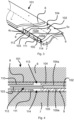
- Fig. 2 shows the first embodiment of the laminating device 1 from Fig. 1 in a cross-sectional view.
- the section runs perpendicular to the longitudinal axis L.
- the tab 3 present on the laminate product 2 is arranged between the first recess 10, which is present in the first lamination sheet 4 adjacent to the first pressure surface 4a, and the second recess 11, which is present adjacent to the second pressure surface 5a of the second lamination sheet 5.
- the first recess 10 and the second recess 11 are arranged mirror-symmetrically to one another with respect to a center plane M defined between the first lamination sheet 4 or the first pressure surface 4a and the second lamination sheet 5 or the second pressure surface 5a.
- the laminate product 2 is clamped under pressure between the first pressure surface 4a of the first lamination sheet 4 and the second pressure surface 5a of the second lamination sheet 5, wherein the first lamination sheet 4 is heated by the first heating plate 6 via the first intermediate material 8 and the second lamination sheet 5 is heated by the second heating plate via the second intermediate material 9, so that the layers present in the laminate product 2 are bonded together.
- the tab 3, which is arranged in sections between at least two layers of the laminate product 2, is thereby advantageously bonded together with the laminate product 2 by the lamination.
- the tab 3 is located at least for the most part between the first recess 10 of the first lamination sheet 4 and the second recess 11 of the second lamination sheet 5, so that the tab 3 is arranged in a cavity 12 defined between the first recess 10 and the second recess 11 during lamination. On the one hand, this prevents contact between the tab 3 and the first lamination sheet 4 and the second lamination sheet 5, and the distance is also increased further, so that the tab 3 is subject to a lower and more uniform heating overall due to the air cushion surrounding it.
- the degree of shrinkage of the tab that usually occurs during lamination is advantageously reduced considerably, so that a consistently high quality of the tab 3 is achieved after lamination has been completed with the usual firm connection to the laminate product 2.
- Fig. 3 shows a second embodiment of a laminating device 101 with laminate product 102 arranged therein in a partially cutaway perspective view. Structurally compared to the first embodiment in Fig. 1 Identical components are provided with the same reference symbols, whereas structurally modified components have been given a reference symbol incremented by 100.
- the second embodiment of a laminating device 101 shown here comprises, like the one in Fig. 1 and 2
- the first embodiment shown comprises a first lamination sheet 104 with a first pressure surface (not visible here) facing the top side 102a of the laminate product 102 and a second lamination sheet 105 with a second pressure surface 105a facing the bottom side of the laminate product 102.
- the first lamination sheet 104 and the second lamination sheet 105 are also made of stainless steel and are designed to be just as thin so that they can be flexibly transported on a transport roller.
- the lamination sheets 104, 105 have holes 4c, 5c in an edge region running laterally parallel to the longitudinal axis L, into which transport pins of a transport roller can engage.
- the second embodiment of the laminating device 101 comprises a first heating plate 6, which is arranged above the first lamination sheet 104 for heating the same, and a second heating plate 7, which is arranged below the second lamination sheet 105 for heating the same.
- a first intermediate material 8 is arranged between the first heating plate 6 and the first lamination sheet 104 and a second intermediate material 9 is arranged between the second heating plate and the second lamination sheet 105, which serves to equalize the pressure and to ensure a more even temperature distribution during the heating phase during lamination.
- the first lamination sheet 104 has a first slot-shaped recess 113 in addition to the first recess (not visible here), and the second lamination sheet 105 has a second slot-shaped recess 114 in addition to the second recess 111.
- at least part of the tab 103 on the side of the laminate product 102 is arranged between the recesses 113, 114 of the first lamination sheet 104 and the second lamination sheet 105, so that particularly heat-sensitive areas of the tab 103 are further away from the first heating plate 6 or the second heating plate 7.
- Fig. 4 shows the second embodiment of the laminating device 101 from Fig. 3 in a cross-sectional view.
- the section runs perpendicular to the longitudinal axis L.
- the laminate product 102 is clamped under pressure between the first pressure surface 104a of the first lamination sheet 104 and the second pressure surface 105a of the second lamination sheet 105, wherein the first lamination sheet 104 is heated by the first heating plate 6 via the first intermediate material 8 and the second lamination sheet 105 is heated by the second heating plate via the second intermediate material 9, so that the layers present in the laminate product 102 are bonded together.
- the tab 103 which is arranged in sections between at least two layers of the laminate product 2, is thereby advantageously bonded together with the laminate product 102 by the lamination.
- the second embodiment of the laminating device 101 shown here has a further modification of the first lamination sheet 104 and the second lamination sheet 105.
- the first lamination sheet 104 has a first slot-shaped recess 113, wherein the first recess 113 is arranged between the first pressure surface 104a and the first depression 110 of the first lamination sheet 104.
- the second lamination sheet 105 has a second slot-shaped recess 114, wherein the second recess 114 is arranged between the second pressure surface 105a and the second depression 111 of the second lamination sheet 105.
- a part of the tab 103 of the laminate product 102 is arranged between the first recess 113 and the second recess 114, so that the cavity 112 is enlarged again in the area of the first recess 113 and the second recess 114, so that the heat introduced by the first heating plate 6 or the second heating plate 7 is further reduced due to the enlarged air cushion in this area.
- the first slot-shaped recess 113 and the second slot-shaped recess 114 In the second embodiment shown here, they are mirror-symmetrically positioned opposite one another. Alternatively, however, it can also be provided that the first recess is offset from the second recess.
- the invention was explained above using an embodiment in which the recesses are designed as grooves with a flat bottom, which is advantageously particularly easy to manufacture.
- the recesses are stepped or uneven, i.e. that the depths of the recesses can be variable at least in a direction transverse to the longitudinal axis L.
- the invention was also explained above using an embodiment in which there is only one recess in the lamination sheet. It goes without saying that several recesses can also be present in the area of the recesses, if necessary.
Landscapes
- Engineering & Computer Science (AREA)
- Manufacturing & Machinery (AREA)
- Laminated Bodies (AREA)
- Lining Or Joining Of Plastics Or The Like (AREA)
Description
- Die Erfindung betrifft eine Laminierungsvorrichtung zur Herstellung eines Laminatproduktes mit einer Lasche. Weiter betrifft die Erfindung ein Verfahren zur Herstellung eines Laminatproduktes mit einer Lasche unter Verwendung der erfindungsgemäßen Laminierungsvorrichtung.
- Aus der Praxis sind Herstellungsverfahren zur Herstellung von geschichteten Laminatprodukten, insbesondere Sicherheitsdokumenten mit Sicherheitsmerkmalen bekannt, wobei bei solchen Verfahren Laminationsbleche verwendet werden, welche als Bezugsebene definierte Andruckflächen aufweisen, die während der Laminierung unter Druck und erhöhter Temperatur mit den zu verbindenden Schichten in Berührung gebracht werden, um die einzelnen Schichten miteinander stoffschlüssig zu verbinden. Bei dem Laminatprodukt kann es sich um ein Datenblatt handeln, welches in einem Reisepass mittels einer Lasche durch Vernähung oder Ähnliches eingebunden werden muss. Die Lasche ist dabei beispielsweise zwischen den zu verbindenden Schichten angeordnet und ragt seitlich heraus, damit das Datenblatt später über die Lasche mit dem Reisepassdeckel gelenkig verbunden werden kann. Die Lasche sollte aufgrund ihrer Funktion als Gelenk gegenüber dem Reisepassdeckel möglichst stabil sein, sodass sich das Datenblatt nicht mit der Zeit lockert oder löst.
- In der Regel weisen die für die Herstellung verwendeten Laminationsbleche im Bereich der Lasche Erhöhungen bzw. zusätzliches Material auf, um den Höhenunterschied zwischen der relativ dünnen Lasche und dem meist dickeren Datenblatt zu überbrücken und hierdurch die Temperatur zu reduzieren. Dies ist insbesondere dann von Bedeutung, wenn die Lasche aus einem Material besteht, welches sich durch die erhöhte Temperatur zusammenzieht. Dies führt dennoch bei manchen Laschenmaterialien, insbesondere thermoplastischem Polyurethan dazu, dass die Lasche eine nicht immer gleichbleibende Qualität aufweist, da diese nach der Laminierung aufgrund der Schrumpfung mangelhaft ist.
-
DE 10 2008 031 654 A1 zeigt ein Verfahren zur Herstellung eines Datenblattes, in dem Information abgespeichert werden können. In das Datenblatt ist eine Lasche eingearbeitet, die aus einem Kunststoffmaterial besteht und sich zum Einbinden in ein Passbuch eignet und ein problemloses Umblättern der Dokumentkarte in dem Passbuch ermöglicht. Die Lasche besteht vorzugsweise aus einem thermoplastischen Elastomer, bevorzugt aus einem thermoplastischen Polyurethan (TPU). Das Datenblatt bzw. der Kartenkörper wird dabei zuvor durch übliche Laminierung mit flachen Laminationsblechen hergestellt und die Lasche anschließend durch Einbringen von Energie in Form von Ultraschallwellen an den Kartenkörper angeschweißt. -
EP 2 945 807 B1 zeigt ein Verfahren zur Herstellung eines Datenblattes, wobei das Datenblatt aus zwei Lagen aus einem organischen Polymerwerkstoff besteht und zwischen den beiden Lagen ein Textil 5 einlamentiert wird, wobei ein Teil des Textils als Lasche außerhalb der beiden Lagen hervorsteht. Für das Verfahren werden zwei Laminationsbleche verwendet, welche im Bereich der Lasche einander zugewandte Stufen oder Erhöhungen aufweisen, um einen Höhenausgleich im Bereich der Lasche zu bewirken. -
DE 10 2004 041 434 A1 zeigt ein Laminations- bzw. Prägeblech für eine Heiß-Kalt-Laminierpresse mit dreidimensionaler Struktur, wobei das Prägeblech auf einer dem herzustellenden Laminatprodukt zugewandten Oberseite, welche eine Bezugsebene bildet, sowohl Erhöhungen als auch Vertiefungen zur Prägung des Laminatproduktes aufweist. Durch die vorgesehenen Erhöhungen bzw. Vertiefungen werden auf dem herzustellenden Laminatprodukt, beispielsweise einem Sicherheitsdokument, wie einem Personalausweis, Reisepass, Identifikationskarte, Kreditkarte, Kundenkarte, Führerschein und dergleichen entsprechend relativ zu der Bezugsebene vertiefte bzw. erhabene Strukturen hergestellt. Die in dem Laminationsblech vorgesehenen Vertiefungen sind linsenförmig, rechteckförmig, parabolartig, elliptisch, trapezförmig, V-förmig oder unregelmäßig geformt. Die während der Laminierung hierdurch geformten dreidimensionalen Gebilde auf dem Laminatprodukt sollen beim visuellen und/oder maschinellen Betrachten einer darunter angeordneten Information den Strahlengang derart beeinflussen, dass eine Veränderung dieser Formation visuell und/oder maschinell gegeben ist. -
DE 10 2008 058 912 A1 zeigt ein Verfahren zur Herstellung von Laminatprodukten und ein Laminationsblech zur Verwendung in dem Verfahren. Das Herstellungsverfahren umfasst ein Zusammentragen von Schichten und das Laminieren der Schichten zu einem schichtförmigen Körper mit einem ersten Bereich, aus dem ein schichtförmiges Dokument erzeugt werden kann und einem zweiten Bereich. Beim Laminieren der Schichten werden in dem zweiten Bereich Erhöhungen erzeugt, welche außerhalb des ersten Bereiches liegen. Das dabei verwendete Laminationsblech weist zur Erzeugung der Erhöhungen in dem zweiten Bereich entsprechende Vertiefungen auf, wobei die Vertiefungen punktförmig oder linienförmig ausgebildet sein können und die ersten Bereiche allseitig umgeben. -
JP 2019 - 195 964 A -
DE 10 2017 205 068 A1 zeigt eine Laminierungsvorrichtung mit einem ersten Laminationsblech und einem zweiten Laminationsblech zur Herstellung eines Laminatproduktes. Das erste Laminationsblech weist eine erste ebene Andruckfläche und eine parallel zu einer Längserstreckung des ersten Laminationsblechs verlaufende nutförmige Aussparung auf, welche sich von einem ersten Rand des ersten Laminationsbleches in Richtung auf ein Zentrum des ersten Laminationsbleches erstreckt. In der nutförmigen Aussparung ist ein Thermoelement eingesetzt, welches zur Überwachung der Temperatur einer Oberseite des Laminatproduktes während der Laminierung vorgesehen ist. -
EP 3 354 479 B1 zeigt eine Laminierungsvorrichtung zur Herstellung eines Laminatproduktes mit einem Datenblatt und einer Lasche, wobei die Lasche eine geringere Dicke als das Datenblatt aufweist. Die Laminierungsvorrichtung umfasst ein erstes Laminationsblech mit einer ebenen Andruckfläche, wobei eine Stufe in dem Laminationsblech vorgesehen ist, welche den Höhenunterschied zwischen dem Datenblatt und der Lasche ausgleicht. Weiter sind in dem Laminationsblech in dem Bereich der ebenen Andruckfläche weitere Vertiefungen vorgesehen, welche zur Ausbildung von taktilen Merkmalen auf der Oberfläche des Laminatproduktes vorgesehen sind. Nachteilig berührt das erste Laminationsblech die Lasche während der Herstellung, sodass die hierbei auftretenden Temperaturen zu entsprechenden Qualitätseinbußen bei Laschen aus insbesondere thermoplastischem Polyurethan führen können. -
DE 10 2004 055 973 A1 zeigt eine Laminierungsvorrichtung zur Herstellung eines Laminatproduktes, umfassend ein erstes Laminationsblech mit einer entlang einer Längserstreckung des ersten Laminationsbleches verlaufenden Erhöhung, welche während der Laminierung im Faltbereich eines Einlageblattes angeordnet wird, wobei jeweils angrenzend an die Erhöhung der Oberseite des Laminatproduktes zugeordnete ebene Andruckflächen an dem Laminationsblech vorgesehen sind. -
DE 10 2015 014 251 A1 zeigt eine Laminierungsvorrichtung zur Herstellung eines Laminatproduktes, umfassend ein erstes Laminationsblech und ein zweites Laminationsblech, wobei das erste Laminationsblech eine erste Stufe aufweist und das zweite Laminationsblech eine zweite Stufe aufweist, sodass das erste Laminationsblech eine erste ebene Andruckfläche zum Laminieren eines dickeren Hauptteils des Laminatproduktes und eine daran angrenzenden Bereich mit einer größeren Wandstärke zum Laminieren einer dünnen Lasche aufweist. Nachteilig wird auch die herzustellende Lasche durch den Kontakt den Stufen berührt, sodass entsprechende Qualitätseinbußen bei zu hohen Temperaturen für bestimmte Materialien der Lasche, insbesondere thermoplastischem Polyurethan auftreten können. -
WO 02/ 092 326 A1 -
US 2015 / 0 027 326 A1 zeigt eine Laminierungsvorrichtung zur Herstellung eines Laminatproduktes, wobei die Laminierungsvorrichtung ein erstes Laminationsblech und ein zweites Laminationsblech umfasst, welche jeweils ebene Andruckflächen aufweisen, wobei im Zentrum der ebenen Andruckflächen eine Vertiefung in Form verschiedener Motive wie ein Baumblatt oder einen Vogel aufweist, sodass in dem Laminatprodukt entsprechende Erhöhungen aufgeprägt werden können. -
DE 10 2013 000 717 A1 zeigt eine Laminierungsvorrichtung zur Herstellung eines Laminatproduktes mit einer Lasche, umfassend ein erstes Laminationsblech mit einer ersten Andruckfläche und einem zweiten Laminationsblech mit einer zweiten Andruckfläche. Die Laminationsbleche weisen dabei gegenüberliegende Stufen für die Lasche des Laminatproduktes auf. - Es ist die Aufgabe der Erfindung, eine Laminierungsvorrichtung zur Herstellung eines Laminatproduktes und ein Verfahren zur Herstellung eines Laminatproduktes anzugeben, welche die Verbindung einer Lasche mit einem Schichtkörper in möglichst gleichbleibend hoher Qualität ermöglichen.
- Die vorgenannte Aufgabe wird erfindungsgemäß durch eine Laminierungsvorrichtung gemäß Anspruch 1 und einem Verfahren gemäß Anspruch 14 gelöst.
- Gemäß einem Aspekt der Erfindung ist eine Laminierungsvorrichtung zur Herstellung eines Laminatproduktes mit einer insbesondere ein Gelenk bildenden Lasche geschaffen. Die Laminierungsvorrichtung umfasst ein entlang einer Längsachse längs erstrecktes erstes Laminationsblech mit einer der Oberseite des Laminatproduktes zugeordneten ersten ebenen Andruckfläche, wobei neben der ersten ebenen Andruckfläche eine erste Vertiefung in dem ersten Laminationsblech vorhanden ist. Die Laminierungsvorrichtung umfasst weiter ein zweites Laminationsblech mit einer der Unterseite des Laminatproduktes zugeordneten zweiten ebenen Andruckfläche, wobei neben der zweiten Andruckfläche eine zweite Vertiefung in dem zweiten Laminationsblech vorhanden ist, wobei die erste Vertiefung und die zweite Vertiefung als Nuten ausgebildet sind, wobei die erste Vertiefung in der Nähe eines Randbereichs des ersten Laminationsbleches und die zweite Vertiefung in der Nähe eines Randbereichs des zweiten Laminationsbleches angeordnet ist. Die erfindungsgemäße Laminierungsvorrichtung zeichnet sich dadurch aus, dass zumindest das erste Laminationsblech zwischen der ersten Andruckfläche und der ersten Vertiefung eine erste Ausnehmung aufweist, welche die erste Andruckfläche und die erste Vertiefung in einer Richtung quer zu der Längsachse voneinander beabstandet. Vorteilhaft ist es hierdurch möglich, die an dem Laminatprodukt durch die Laminierung zu befestigende Lasche zwischen die erste Vertiefung und die zweite Vertiefung anzuordnen, sodass die Lasche während der Laminierung nicht in Kontakt mit den Andruckflächen steht und darüber hinaus sogar einen vergrößerten Abstand zu dem Laminationsblech aufweist. Vorteilhaft können die als Nuten ausgebildete erste Vertiefung und die zweite Vertiefung mit wohl definierten Maßen hergestellt werden, sodass sichergestellt werden kann, dass die Lasche einen wohl definierten Abstand zu dem Laminationsblech bzw. den Vertiefungen aufweist. Vorteilhaft führt dies im Gegensatz zu dem aus dem Stand der Technik bekannten Überbrücken durch Verwendung einer Erhöhung bzw. von Ausgleichsmaterial zu einer verbesserten Qualität der Lasche, insbesondere bei Verwendung von Laschen aus einem Kunststoffmaterial wie thermoplastischem Polyurethan, welches bei erhöhter Temperatur schrumpft. Da die Lasche insbesondere zur gelenkigen Verbindung des Laminatproduktes beispielsweise in einem Reisepass oder ähnlichem geeignet sein soll, muss die an dem Laminatprodukt anzuordnende Lasche möglichst von hoher Qualität sein. Insbesondere soll vermieden werden, dass die mit der Zeit immer wieder vorgenommenen gelenkigen Bewegungen des Laminatproduktes über das durch die Lasche gebildete Gelenk möglichst nicht zu einer Lockerung oder sogar einem Herauslösen des Laminatproduktes führen.
- Besonders bevorzugt sind die erste Vertiefung und die zweite Vertiefung spiegelsymmetrisch zu einer zwischen dem ersten Laminationsblech und dem zweiten Laminationsblech definierten Mittelebene angeordnet. Vorteilhaft kann die Lasche so über ihre gesamte Länge in einer wohl definierten Position zwischen der ersten Vertiefung und der zweiten Vertiefung angeordnet werden, sodass jeder Punkt der Oberseite der Lasche und der ihm gegenüberliegende Punkt der Unterseite der Lasche jeweils wohl definierte Abstände zu dem Laminationsblech aufweisen.
- Besonders bevorzugt verlaufen die erste Vertiefung und die zweite Vertiefung jeweils parallel zu der Längsachse. Vorteilhaft ist es hierdurch möglich, die an dem Laminatprodukt vorhandene Lasche ebenso parallel zu der Längsachse anzuordnen, sodass die Lasche über ihre gesamte Länge zwischen die erste Vertiefung und die zweite Vertiefung während der Laminierung angeordnet werden kann.
- In einer besonders bevorzugten Ausbildung ist vorgesehen, dass die erste Vertiefung und zweite Vertiefung verschiedene Tiefen aufweisen. Vorteilhaft können so asymmetrische Aufbauten des Laminatproduktes oder auch der Lasche selbst flexibel berücksichtigt werden. Beispielsweise könnte die Lasche auch mehrschichtige aufgebaut sein, wobei hierdurch unterschiedliche Temperaturverläufe in Bezug auf eine Oberseite der Lasche und eine Unterseite der Lasche vorteilhaft oder sogar notwendig sein können, welche durch die Anpassung der jeweiligen Tiefen der ersten Vertiefung oder der zweiten Vertiefung realisiert werden kann. Alternativ hierzu kann es jedoch auch vorgesehen sein, dass die erste Vertiefung und die zweite Vertiefung dieselben Tiefen aufweisen.
- In einer vorteilhaften Weiterbildung weist die erste Vertiefung eine erste Tiefe zwischen 40 und 90 µm und zweite Vertiefung eine zweite Tiefe zwischen 40 und 90 µm auf. Besonders bevorzugt weist die erste Vertiefung und die zweite Vertiefung jeweils einen flachen Bodenbereich auf. Zweckmäßigerweise definiert der Bodenbereich eine parallel zu der Mittelebene versetzte Ebene. Vorteilhaft wird hierdurch ein jeweils möglichst gleichbleibender Abstand zwischen der Lasche und der ersten Vertiefung bzw. der zweiten Vertiefung über die gesamte Länge der Lasche erreicht.
- Zweckmäßigerweise definieren die erste Vertiefung und die zweite Vertiefung einen sich parallel zur Längsachse längserstreckenden Hohlraum. Vorteilhaft ist der Hohlraum dazu vorgesehen, dass die Lasche des Laminatproduktes während der Laminierung zumindest größtenteils in dem Hohlraum positioniert wird, sodass die Lasche von den Laminationsblechen weiter beabstandet ist und zudem eine günstigere Temperaturverteilung erzielt wird. Insbesondere wird die Lasche nicht so schnell und so stark erhitzt, während das sonstige Laminatprodukt mit den üblichen Temperaturen und Drücken laminiert wird.
- Besonders bevorzugt weist der Hohlraum oder die Vertiefungen eine senkrecht zu der Längsachse verlaufende Breite auf, welche mindestens die Breite der in dem Hohlraum anzuordnenden Lasche aufweist. Vorteilhaft wird so sichergestellt, dass die Lasche gegebenenfalls auch vollständig mit ihrer ganzen Breite zwischen die erste Vertiefung und die zweite Vertiefung angeordnet werden kann.
- Bei einer ersten bevorzugten Ausgestaltung grenzt die erste Andruckfläche an die erste Vertiefung und die zweite Andruckfläche an die zweite Vertiefung an. Vorteilhaft ist es gegenüber einem unbearbeiteten Laminationsblech lediglich erforderlich, die entsprechenden Vertiefungen in die Laminationsbleche einzuarbeiten. Die Vertiefung können dabei sowohl mechanisch als auch chemisch hergestellt werden.
- In einer besonders bevorzugten Ausgestaltung ist die erste Ausnehmung als Schlitz ausgebildet. Besonders bevorzugt weist das zweite Laminationsblech zwischen der zweiten Andruckfläche und der zweiten Vertiefung eine zweite Ausnehmung auf, welche die zweite Andruckfläche und die zweite Vertiefung in einer Richtung quer, insbesondere senkrecht zu der Längsachse voneinander beabstandet. Vorteilhaft können in dem Bereich der Ausnehmung besonders hitzeempfindliche Bestandteile, welche an der Lasche oder zumindest in einem an die Lasche angrenzenden Bereich des Laminatproduktes angeordnet sind, nochmals besser vor der während der Laminierung auftretenden Wärme, welche zur Laminierung bzw. Verbindung der in dem Laminatprodukt zu verbindenden Schichten notwendig ist, geschützt werden.
- Nach einem weiteren Aspekt der Erfindung wird ein Verfahren zur Herstellung eines mehrschichtigen Laminatproduktes angegeben, umfassend in einem ersten Verfahrensschritt ein Bereitstellen einer Laminierungsvorrichtung, wobei die Laminierungsvorrichtung wie vorstehend beschrieben ausgebildet ist. In einem zweiten Verfahrensschritt ist das Positionieren eines Stapels von zumindest zwei miteinander zu verbindenden Schichten und einer zwischen den Schichten angeordneten, seitlich abragenden Lasche zwischen dem ersten Laminationsblech und dem zweiten Laminationsblech vorgesehen, wobei die erste Andruckfläche des ersten Laminationsbleches oberhalb der Oberseite der obersten Schicht des herzustellenden Laminatproduktes und die zweite Andruckfläche des zweiten Laminationsbleches unterhalb der Unterseite der untersten Schicht des herzustellen Laminatproduktes angeordnet wird. Weiter umfasst das Verfahren in einem dritten Verfahrensschritt das Laminieren der zu verbindenden Schichten unter Druck und erhöhter Temperatur. Das erfindungsgemäße Verfahren zeichnet sich dadurch aus, dass die Lasche nach dem Positionieren zumindest teilweise zwischen der ersten Vertiefung in dem ersten Laminationsblech und der zweiten Vertiefung in den zweiten Laminationsblech angeordnet ist. Vorteilhaft wird die Lasche während des nachfolgenden Verfahrensschrittes des Laminierens keiner zu hoher Temperatur ausgesetzt, sodass die Lasche nur unwesentlich in seiner Ausdehnung beeinflusst wird und somit eine gleichbleibend hohe Qualität aufweist.
- Besonders bevorzugt wird die Lasche parallel zu der Längsachse des ersten Laminationsbleches bzw. den Längsstreckungen der ersten Vertiefung und der zweiten Vertiefung beim Positonieren des Stapels Schichten ausgerichtet. Vorteilhaft so sichergestellt, dass die Lasche über ihre gesamte Länge und für eine wohl definierte Breite zwischen der ersten Vertiefung und der zweiten Vertiefung während der nachfolgenden Laminierung angeordnet ist.
- Weitere Vorteile, Weiterbildungen und Eigenschaften der Erfindung ergeben sich aus der nachstehenden Beschreibung eines bevorzugten Ausführungsbeispiels sowie aus den abhängigen Ansprüchen.
- Die Erfindung wird nunmehr unter Bezugnahme auf die anliegenden Zeichnungen anhand bevorzugter Ausführungsbeispiele der Erfindung näher erläutert.
- Fig. 1
- zeigt ein erstes Ausführungsbeispiel einer Laminierungsvorrichtung mit darin angeordneten Laminatprodukt in einer teilweise freigeschnittenen Perspektivansicht.
- Fig. 2
- zeigt das erste Ausführungsbeispiel der Laminierungsvorrichtung aus
Fig. 1 in einer Querschnittsansicht. - Fig. 3
- zeigt ein zweites Ausführungsbeispiel einer Laminierungsvorrichtung mit darin angeordneten Laminatprodukt in einer teilweise freigeschnittenen Perspektivansicht.
- Fig. 4
- zeigt das zweite Ausführungsbeispiel der Laminierungsvorrichtung aus
Fig. 3 in einer Querschnittsansicht. -
Fig 1 zeigt ein erstes Ausführungsbeispiel einer Laminierungsvorrichtung 1 mit darin angeordnetem Laminatprodukt 2 mit einer seitlich an dem Laminatprodukt 2 angeordneten Lasche 3. Das Laminatprodukt 2 ist vorliegend als mehrschichtige Datenseite für einen Reisepass ausgebildet. Die Lasche 3 ist als Laschenstreifen aus thermoplastischem Polyurethan ausgebildet. Die Laminierungsvorrichtung 1 umfasst ein sich in Richtung einer Längsachse L längs erstrecktes erstes Laminationsblech 4 mit einer der Oberseite 2a des Laminatproduktes 2 zugewandten ersten Andruckfläche, welche hier nicht sichtbar ist. - Weiter umfasst die Laminierungsvorrichtung 1 ein zweites Laminationsblech 5 mit einer der Unterseite des Laminatproduktes 2 zugewandten zweiten Andruckfläche 5a. Das erste Laminationsblech 4 als auch das zweite Laminationsblech 5 bestehen aus Edelstahl, sodass die Andruckflächen besonders glatt und hitzebeständig sind. Gleichzeitig sind die Laminationsbleche 4, 5 so dünn, dass diese flexibel auf einer Transportrolle transportiert werden können. Hierzu weisen die Laminationsbleche 4, 5 in einem seitlichen parallel zu der Längsachse L verlaufendem Randbereich Bohrungen 4c, 5c auf, in welche Transportstifte einer Transportrolle eingreifen können.
- Die Laminierungsvorrichtung 1 umfasst weiter eine erste Heizplatte 6, welche oberhalb des ersten Laminationsbleches 4 zur Beheizung desselben angeordnet ist und eine zweite Heizplatte 7, welche unterhalb des zweiten Laminationsbleches 5 zur Beheizung desselben angeordnet ist. Zwischen der ersten Heizplatte 6 und einer Oberseite 4b des ersten Laminationsbleches 4 ist ein erstes Zwischenmaterial 8 und zwischen der zweiten Heizplatte 7 und dem zweiten Laminationsblech 5 ist ein zweites Zwischenmaterial 9 angeordnet, welche während der Laminierung jeweils dem Druckausgleich und einer gleichmäßigeren Temperaturverteilung bei der Aufheizphase dienen.
- Das erste Laminationsblech 4 weist eine hier nicht sichtbare erste Vertiefung und das zweite Laminationsblech 5 weist eine zweite längs erstreckte Vertiefung 11 auf. Die zweite Vertiefung 11 ist als Nut ausgebildet und wird in der Richtung senkrecht zu der Längsachse L durch den Randbereich des zweiten Laminationsbleches 5, in dem die Bohrungen 5c vorhanden sind, und der zweiten Andruckfläche 5a begrenzt. Die zweite Vertiefung 11 weist dabei eine Breite auf, welche größer als die Breite der Lasche 3 ist, sodass die Lasche 3 gegebenenfalls vollständig über einen Bereich der zweiten Vertiefung 11 bzw. unterhalb der ersten Vertiefung angeordnet werden kann. In der hier gezeigten Situation ist das Laminatprodukt 2 so positioniert, wie es während des Laminierungsvorganges vorgesehen ist.
-
Fig. 2 zeigt das erste Ausführungsbeispiel der Laminierungsvorrichtung 1 ausFig. 1 in einer Querschnittsansicht. Der Schnitt verläuft dabei senkrecht zu der Längsachse L. In dieser Ansicht ist gut zu erkennen, dass die an dem Laminatprodukt 2 vorhandene Lasche 3 zwischen der ersten Vertiefung 10, welche an die ersten Andruckfläche 4a angrenzend in dem ersten Laminationsblech 4 vorhanden ist, und der zweiten Vertiefung 11, welche an die zweiten Andruckfläche 5a des zweiten Laminationsbleches 5 angrenzend vorhanden ist, angeordnet ist. Die erste Vertiefung 10 und die zweite Vertiefung 11 sind dabei spiegelsymmetrisch zu einer zwischen dem ersten Laminationsblech 4 bzw. der ersten Andruckfläche 4a und dem zweiten Laminationsblech 5 bzw. der zweiten Andruckfläche 5a definierten Mittelebene M zueinander angeordnet. - Das Laminatprodukt 2 ist in der hier gezeigten Situation zwischen der ersten Andruckfläche 4a des ersten Laminationsbleches 4 und der zweiten Andruckfläche 5a des zweiten Laminationsbleches 5 unter Druck eingespannt, wobei das erste Laminationsblech 4, vermittelt über das erste Zwischenmaterial 8, durch die erste Heizplatte 6 aufgeheizt wird und das zweite Laminationsblech 5, vermittelt über das zweite Zwischenmaterial 9, durch die zweite Heizplatte aufgeheizt wird, so dass die in dem Laminatprodukt 2 vorhandenen Schichten stoffschlüssig verbunden werden. Die Lasche 3, welche zwischen zumindest zwei Schichten des Laminatproduktes 2 abschnittsweise angeordnet ist, wird hierdurch vorteilhaft ebenso durch die Laminierung mit dem Laminatprodukt 2 stoffschlüssig verbunden.
- Die Lasche 3 befindet sich zumindest größtenteils zwischen der ersten Vertiefung 10 des ersten Laminationsbleches 4 und der zweiten Vertiefung 11 des zweiten Laminationsbleches 5, sodass die Lasche 3 während der Laminierung in einem zwischen der ersten Vertiefung 10 und der zweiten Vertiefung 11 definierten Hohlraum 12 angeordnet ist. Hierdurch wird auf der einen Seite ein Kontakt der Lasche 3 mit dem ersten Laminationsblech 4 und den zweiten Laminationsblech 5 vermieden und zudem nochmals der Abstand weiter vergrößert, sodass die Lasche 3 aufgrund des sie umgebenden Luftpolsters einer insgesamt geringeren und auch gleichmäßigeren Erwärmung unterliegt. Vorteilhaft reduziert sich der bei der Laminierung üblicherweise auftretende Schrumpfungsgrad der Lasche erheblich, sodass eine gleichbleibend hohe Qualität der Lasche 3 nach Beendigung der Laminierung bei gewohnt fester Verbindung mit dem Laminatprodukt 2 erzielt wird.
-
Fig. 3 zeigt ein zweites Ausführungsbeispiel einer Laminierungsvorrichtung 101 mit darin angeordneten Laminatprodukt 102 in einer teilweise freigeschnittenen Perspektivansicht. Strukturell gegenüber dem ersten Ausführungsbeispiel inFig. 1 gleiche Bauteile sind mit denselben Bezugszeichen versehen, wohingegen strukturell veränderte Bauteile ein um 100 inkrementiertes Bezugszeichen erhalten haben. - Das hier gezeigte zweite Ausführungsbeispiel einer Laminierungsvorrichtung 101 umfasst ebenso wie das in
Fig. 1 und 2 gezeigte erste Ausführungsbeispiel ein erstes Laminationsblech 104 mit einer der Oberseite 102a des Laminatproduktes 102 zugewandten, hier nicht sichtbare ersten Andruckfläche und ein zweites Laminationsblech 105 mit einer der Unterseite des Laminatproduktes 102 zugewandten zweiten Andruckfläche 105a. Das erste Laminationsblech 104 und das zweite Laminationsblech 105 bestehen ebenso aus Edelstahl und sind ebenso dünn ausgeführt, dass diese flexibel auf einer Transportrolle transportiert werden können. Hierzu weisen die Laminationsbleche 104, 105 in einem seitlich parallel zu der Längsachse L verlaufenden Randbereich Bohrungen 4c, 5c auf, in welche Transportstifte einer Transportrolle eingreifen können. - Ebenso umfasst das zweite Ausführungsbeispiel der Laminierungsvorrichtung 101 eine erste Heizplatte 6, welche oberhalb des ersten Laminationsbleches 104 zur Beheizung desselben angeordnet ist und eine zweite Heizplatte 7, welche unterhalb des zweiten Laminationsbleches 105 zur Beheizung desselben angeordnet ist. Auch hier ist zwischen der ersten Heizplatte 6 und dem ersten Laminationsblech 104 ein erstes Zwischenmaterial 8 und zwischen der zweiten Heizplatte und dem zweiten Laminationsblech 105 ein zweites Zwischenmaterial 9 angeordnet, welches den Druckausgleich und einer gleichmäßigeren Temperaturverteilung bei der Aufheizphase während der Laminierung dient.
- Das erste Laminationsblech 104 weist neben der hier nicht sichtbaren ersten Vertiefung eine erste schlitzförmige Ausnehmung 113 auf und das zweite Laminationsblech 105 weist neben der zweiten Vertiefung 111 eine zweite schlitzförmige Ausnehmung 114 auf. Vorteilhaft ist zumindest ein Teil der an dem Laminatprodukt 102 seitlich vorhandenen Lasche 103 zwischen den Ausnehmungen 113, 114 des ersten Laminationsbleches 104 und des zweiten Laminationsbleches 105 angeordnet, sodass besonders hitzeempfindliche Bereiche der Lasche 103 nochmals weiter von der ersten Heizplatte 6 bzw. der zweiten Heizplatte 7 beabstandet sind.
-
Fig. 4 zeigt das zweite Ausführungsbeispiel der Laminierungsvorrichtung 101 ausFig. 3 in einer Querschnittsansicht. Der Schnitt verläuft dabei senkrecht zu der Längsachse L. Das Laminatprodukt 102 ist in der hier gezeigten Situation zwischen der ersten Andruckfläche 104a des ersten Laminationsbleches 104 und der zweiten Andruckfläche 105a des zweiten Laminationsbleches 105 unter Druck eingespannt, wobei das erste Laminationsblech 104, vermittelt über das erste Zwischenmaterial 8, durch die erste Heizplatte 6 aufgeheizt wird und das zweite Laminationsblech 105, vermittelt über das zweite Zwischenmaterial 9, durch die zweite Heizplatte aufgeheizt wird, so dass die in dem Laminatprodukt 102 vorhandenen Schichten stoffschlüssig verbunden werden. Die Lasche 103, welche zwischen zumindest zwei Schichten des Laminatproduktes 2 abschnittsweise angeordnet ist, wird hierdurch vorteilhaft durch die Laminierung mit dem Laminatprodukt 102 stoffschlüssig verbunden. - Zusätzlich zu dem ersten Ausführungsbeispiel aus
Fig.1 und 2 weist das hier gezeigte zweite Ausführungsbeispiel der Laminierungsvorrichtung 101 eine weitere Modifikation des ersten Laminationsbleches 104 und des zweiten Laminationsbleches 105. Das erste Laminationsblech 104 weist eine erste schlitzförmige Ausnehmung 113 auf, wobei die erste Ausnehmung 113 zwischen der ersten Andruckfläche 104a und der ersten Vertiefung 110 des ersten Laminationsbleches 104 angeordnet ist. Entsprechend weist das zweite Laminationsblech 105 eine zweite schlitzförmige Ausnehmung 114 auf, wobei die zweite Ausnehmung 114 zwischen der zweiten Andruckfläche 105a und der zweiten Vertiefung 111 des zweiten Laminationsbleches 105 angeordnet ist. Vorteilhaft ist ein Teil der Lasche 103 des Laminatproduktes 102 zwischen der ersten Ausnehmung 113 und der zweiten Ausnehmung 114 angeordnet, sodass der Hohlraum 112 im Bereich der ersten Ausnehmung 113 und der zweiten Ausnehmung 114 nochmals vergrößert ist, so dass die durch die erste Heizplatte 6 bzw. die zweite Heizplatte 7 eingebrachte Wärme aufgrund des vergrößerten Luftpolsters in diesem Bereich weiter reduziert wird. Die erste schlitzförmige Ausnehmung 113 und die zweite schlitzförmige Ausnehmung 114 liegen sich in dem hier gezeigten zweiten Ausführungsbeispiel spiegelsymmetrisch gegenüber. Alternativ hierzu kann es jedoch auch vorgesehen sein, dass die erste Ausnehmung gegenüber der zweiten Ausnehmung versetzt angeordnet ist. - Vorstehend wurde die Erfindung anhand eines Ausführungsbeispiels erläutert, bei dem die Vertiefungen als Nuten mit einem ebenen Boden ausgebildet sind, was vorteilhaft besonders einfach herzustellen ist. Je nach Aufbau der zwischen den Vertiefungen anzuordnenden Lasche kann es jedoch auch vorgesehen sein, dass die Vertiefungen gegebenenfalls gestuft oder uneben ausgebildet sind, d.h. dass die Tiefen der Vertiefungen zumindest in einer Richtung quer zu der Längsachse L variabel sein können. Weiter wurde die Erfindung vorstehend anhand eines Ausführungsbeispiels erläutert, bei dem nur eine Ausnehmung in dem Laminationsblech vorhanden ist. Es versteht sich, dass auch mehrere Ausnehmungen im Bereich der Vertiefungen vorhanden sein können, soweit erforderlich.
Claims (15)
- Laminierungsvorrichtung zur Herstellung eines Laminatproduktes (2; 102) mit einer Lasche (3; 103), umfassendein entlang einer Längsachse (L) längs erstrecktes erstes Laminationsblech (4; 104) mit einer der Oberseite (2a) des Laminatproduktes (2) zugeordneten ersten ebenen Andruckfläche (4a; 104a), wobei neben der ersten ebene Andruckfläche (4a; 104a) eine erste Vertiefung (10; 110) in dem ersten Laminationsblech (4; 104) vorhanden ist,ein zweites Laminationsblech (5; 105) mit einer der Unterseite des Laminatproduktes (2; 102) zugeordneten zweiten ebenen Andruckfläche (5a; 105a), wobei neben der zweiten ebenen Andruckfläche (5a; 105a) eine zweite Vertiefung (11; 111) in dem zweiten Laminationsblech (5; 105) vorhanden ist, wobei die erste Vertiefung (10; 110) und die zweite Vertiefung (11; 111) als Nuten ausgebildet sind, wobei die erste Vertiefung (10; 110) in der Nähe eines Randbereichs des ersten Laminationsbleches (4; 104) und die zweite Vertiefung (11; 111) in der Nähe eines Randbereichs des zweiten Laminationsbleches (5; 105) angeordnet ist,dadurch gekennzeichnet,
dass zumindest das erste Laminationsblech (104) zwischen der ersten Andruckfläche (104a) und der ersten Vertiefung (110) eine erste Ausnehmung (113) aufweist, welche die erste Andruckfläche (104a) und die erste Vertiefung (110) in einer Richtung quer zu der Längsachse (L) voneinander beabstandet. - Laminierungsvorrichtung nach Anspruch 1, dadurch gekennzeichnet, dass der Randbereich seitlich parallel zu der Längsachse (L) verläuft.
- Laminierungsvorrichtung nach Anspruch 2, dadurch gekennzeichnet, dass das erste Laminationsblech (4; 104) und das zweite Laminationsblech (5; 105) in dem Randbereich Bohrungen (4c; 5c) aufweist, in welchen Transportstifte einer Transportrolle eingreifen können.
- Laminierungsvorrichtung nach einem der vorhergehenden Ansprüche, dadurch gekennzeichnet, dass die erste Vertiefung (10; 110) und die zweite Vertiefung (11; 111) spiegelsymmetrisch zu einer zwischen dem ersten Laminationsblech (4; 104) und dem zweiten Laminationsblech (5; 105) definierten Mittelebene (M) angeordnet sind.
- Laminierungsvorrichtung nach einem der vorhergehenden Ansprüche, dadurch gekennzeichnet, dass die erste Vertiefung (10; 110) und die zweite Vertiefung (11; 111) jeweils parallel zu der Längsachse (L) geradlinig verlaufen.
- Laminierungsvorrichtung nach einem Ansprüche 1,2, 3 oder 5, dadurch gekennzeichnet, dass die erste Vertiefung (10; 110) und die zweite Vertiefung (11; 111) verschiedene Tiefen aufweisen.
- Laminierungsvorrichtung nach einem der vorhergehenden Ansprüche, dadurch gekennzeichnet, dass die erste Vertiefung (10; 110) eine erste Tiefe zwischen 40 und 90 µm und die zweite Vertiefung (11; 111) eine zweite Tiefe zwischen 40 und 90 µm aufweist.
- Laminierungsvorrichtung nach einem der vorhergehenden Ansprüche, dadurch gekennzeichnet, dass die erste Vertiefung (10; 110) und die zweite Vertiefung (11; 111) jeweils einen flachen Bodenbereich aufweisen.
- Laminierungsvorrichtung nach einem der vorhergehenden Ansprüche, dadurch gekennzeichnet, dass die erste Vertiefung (10; 110) und die zweite Vertiefung (11; 111) einen längserstreckten Hohlraum (12, 112) definieren.
- Laminierungsvorrichtung nach Anspruch 9, dadurch gekennzeichnet, dass der Hohlraum (12; 112) oder die Vertiefungen (10; 110; 11; 111) eine senkrecht zu der Längsachse verlaufende Breite aufweisen, welche mindestens die Breite der in dem Hohlraum (12; 112) anzuordnenden Lasche (3) aufweist.
- Laminierungsvorrichtung nach einem der vorhergehenden Ansprüche, dadurch gekennzeichnet, dass die erste Andruckfläche (4a; 104a) an die erste Vertiefung (10; 110) und die zweite Andruckfläche (5a; 105a) an die zweite Vertiefung (11; 111) angrenzt.
- Laminierungsvorrichtung nach einem der vorhergehenden Ansprüche, dadurch gekennzeichnet, dass das zweite Laminationsblech (105) zwischen der zweiten Andruckfläche (105a) und der zweiten Vertiefung (111) eine zweite Ausnehmung (114) aufweist, welche die zweite Andruckfläche (105a) und die zweite Vertiefung (111) in einer Richtung quer, insbesondere senkrecht zu der Längsachse (L) voneinander beabstandet.
- Laminierungsvorrichtung nach einem der vorhergehenden Ansprüche, dadurch gekennzeichnet, dass die erste Ausnehmung (113) als Schlitz ausgebildet ist.
- Verfahren zur Herstellung eines Laminatproduktes (2; 102), umfassendBereitstellen einer Laminierungsvorrichtung (1; 101), wobei die Laminierungsvorrichtung (1; 101) nach einem der vorhergehenden Ansprüche ausgebildet ist,Positionieren eines Stapels von zumindest zwei miteinander zu verbindenden Schichten und einer zwischen den Schichten angeordneten, seitlich abragenden Lasche (3; 103) zwischen dem ersten Laminationsblech (4;104) und dem zweiten Laminationsblech (5; 105), undLaminieren der zu verbindenden Schichten unter Druck und erhöhter Temperatur,dadurch gekennzeichnet,dass die Lasche (3; 103) nach dem Positionieren zumindest teilweise zwischen der ersten Vertiefung (10; 110) in dem ersten Laminationsblech (4; 104) und der zweiten Vertiefung (11; 111) in dem zweiten Laminationsblech (105) angeordnet ist.
- Verfahren gemäß Anspruch 14, dadurch gekennzeichnet, dass die Lasche (3) parallel zu der Längsachse (L) des ersten Laminationsbleches (4; 104) bzw. den Längsstreckungen der ersten Vertiefung (10; 110) und der zweiten Vertiefung (11; 111) beim Positonieren des Stapels Schichten ausgerichtet wird.
Applications Claiming Priority (1)
| Application Number | Priority Date | Filing Date | Title |
|---|---|---|---|
| DE102022118339.4A DE102022118339A1 (de) | 2022-07-21 | 2022-07-21 | Laminierungsvorrichtung zur Herstellung eines Laminatproduktes mit einer Lasche und Verfahren zur Herstellung eines Laminatproduktes |
Publications (3)
| Publication Number | Publication Date |
|---|---|
| EP4309912A1 EP4309912A1 (de) | 2024-01-24 |
| EP4309912B1 true EP4309912B1 (de) | 2024-11-06 |
| EP4309912C0 EP4309912C0 (de) | 2024-11-06 |
Family
ID=87280346
Family Applications (1)
| Application Number | Title | Priority Date | Filing Date |
|---|---|---|---|
| EP23185342.5A Active EP4309912B1 (de) | 2022-07-21 | 2023-07-13 | Laminierungsvorrichtung zur herstellung eines laminatproduktes mit einer lasche und verfahren zur herstellung eines laminatproduktes |
Country Status (2)
| Country | Link |
|---|---|
| EP (1) | EP4309912B1 (de) |
| DE (1) | DE102022118339A1 (de) |
Family Cites Families (12)
| Publication number | Priority date | Publication date | Assignee | Title |
|---|---|---|---|---|
| WO2002092326A1 (de) | 2001-05-14 | 2002-11-21 | Elmicron Ag | Pressstempel |
| DE102004041434B4 (de) | 2004-08-27 | 2013-10-10 | Credit Card Supplies | Verfahren zur Herstellung eines Prägeblechs für eine Heiß-Kalt-Laminierpresse mit dreidimensionalen Strukturen |
| DE102004055973A1 (de) | 2004-11-19 | 2006-06-08 | Bundesdruckerei Gmbh | Einlageblatt, insbesondere für ein buchartiges Identifikationsdokument, Verfahren und Vorrichtung zur Herstellung eines Einlageblattes |
| DE102008031654A1 (de) | 2008-07-03 | 2010-01-14 | Bundesdruckerei Gmbh | Verfahren zum Herstellen einer Dokumentenkarte, die in ein als Buch ausgeführtes Sicherheitsdokument einfügbar ist, und Dokumentenkarte |
| DE102008058912B4 (de) | 2008-11-25 | 2016-01-21 | Bundesdruckerei Gmbh | Verfahren zur Herstellung und Weiterverarbeitung eines schichtförmigen Körpers |
| US9079373B2 (en) | 2010-10-18 | 2015-07-14 | Preco, Inc. | System and method for embossing/debossing impressionable material |
| DE102013000717A1 (de) | 2013-01-17 | 2014-07-17 | Bayer Material Science Ag | Datenblatt für ein Sicherheits- und/oder Wertdokument |
| DE102015107732B4 (de) | 2015-05-18 | 2017-06-22 | Bundesdruckerei Gmbh | Verfahren zur Herstellung eines Buchblocks, insbesondere für ein buchartiges Dokument sowie ein Einlageblatt und ein Buchblock |
| DE102015014251A1 (de) | 2015-11-05 | 2017-05-11 | Veridos Gmbh | Datenseite mit Scharnierbereich für ein Passbuch |
| EP3354479B1 (de) | 2017-01-26 | 2019-10-23 | Paragon Id | Datenseite für ein identifikationsbuch und verfahren zur herstellung davon |
| DE102017205068A1 (de) | 2017-03-24 | 2018-09-27 | Bundesdruckerei Gmbh | Laminationsblech und Vorrichtung zum Messen einer Temperatur beim Laminieren eines Substratschichtenstapels |
| JP2019195964A (ja) | 2018-05-10 | 2019-11-14 | 独立行政法人 国立印刷局 | ヒンジ付きデータページ及び冊子類 |
-
2022
- 2022-07-21 DE DE102022118339.4A patent/DE102022118339A1/de active Pending
-
2023
- 2023-07-13 EP EP23185342.5A patent/EP4309912B1/de active Active
Also Published As
| Publication number | Publication date |
|---|---|
| DE102022118339A1 (de) | 2024-02-01 |
| EP4309912C0 (de) | 2024-11-06 |
| EP4309912A1 (de) | 2024-01-24 |
Similar Documents
| Publication | Publication Date | Title |
|---|---|---|
| EP1989667B1 (de) | Verfahren und halbzeug zur herstellung eines inlays | |
| DE112009005177B4 (de) | Kraftübertragungszugmittel | |
| DE102007058555A1 (de) | Mehrschichtiges Substrat und Verfahren zur Herstellung desselben | |
| DE19654902A1 (de) | Chipkarte | |
| EP3189554B1 (de) | Strömungselement, bipolarplatte und verfahren zum herstellen eines strömungselements | |
| EP2303603B1 (de) | Verfahren und vorrichtung zum einbringen eines sicherheitsmerkmals in ein wert- oder sicherheitsdokument | |
| EP2303596B1 (de) | Verfahren zum herstellen einer dokumentenkarte, die in ein als buch ausgeführtes sicherheitsdokument einfügbar ist, und dokumentenkarte | |
| EP1814723B1 (de) | Einlageblatt, insbesondere für ein buchartiges identifikationsdokument, verfahren und vorrichtung zur herstellung eines einlageblattes | |
| DE102020118216A1 (de) | Plattenartiger Fluidbehälter | |
| DE102016117798A1 (de) | Verfahren zur Herstellung eines vorgeformten Verbundhalbzeugs sowie Verfahren zur Herstellung eines Faserverbundbauteils | |
| EP4309912B1 (de) | Laminierungsvorrichtung zur herstellung eines laminatproduktes mit einer lasche und verfahren zur herstellung eines laminatproduktes | |
| EP3297844B1 (de) | Verfahren zur herstellung eines buchblocks, insbesondere für ein buchartiges dokument sowie ein einlageblatt und ein buchblock | |
| DE2825043C2 (de) | Preßverformbare Wellpappentafel und Verfahren zu deren Herstellung | |
| DE102008058912B4 (de) | Verfahren zur Herstellung und Weiterverarbeitung eines schichtförmigen Körpers | |
| EP3753724B1 (de) | Verfahren zur herstellung eines presspolsters sowie pressblechset | |
| EP3800749B1 (de) | Verfahren zur herstellung eines elektrisch leitenden kontaktelements, elektrisch leitendes kontaktelement und hülse mit einem elektrisch leitenden kontaktelement | |
| EP1803548A1 (de) | Heizplatte für eine Plattenpresse | |
| EP4065332B1 (de) | Verwendung eines endlosbandes als trägerband oder prozessband | |
| DE10307808B4 (de) | Verfahren zur Verminderung des Reflexwertes einer mikroprismatischen Reflexfolie | |
| EP3312008B1 (de) | Verfahren zum laminieren von mehreren in einem stapel angeordneten schichten zu einem datenträger | |
| DE102016014995A1 (de) | Umschlag für ein buchartiges Wert- oder Sicherheitsdokument | |
| EP4357147A1 (de) | Datenseite mit sicherheitsscharnier | |
| EP2128319A1 (de) | Zweilagiges Systemteil für ein Stricksystem | |
| DE20008067U1 (de) | Flächiges Verbundbauteil | |
| DE202014101671U1 (de) | Optimale Sandwichkernstrukturen und Formwerkzeuge für die Massenproduktion von Sandwichstrukturen |
Legal Events
| Date | Code | Title | Description |
|---|---|---|---|
| PUAI | Public reference made under article 153(3) epc to a published international application that has entered the european phase |
Free format text: ORIGINAL CODE: 0009012 |
|
| STAA | Information on the status of an ep patent application or granted ep patent |
Free format text: STATUS: THE APPLICATION HAS BEEN PUBLISHED |
|
| AK | Designated contracting states |
Kind code of ref document: A1 Designated state(s): AL AT BE BG CH CY CZ DE DK EE ES FI FR GB GR HR HU IE IS IT LI LT LU LV MC ME MK MT NL NO PL PT RO RS SE SI SK SM TR |
|
| STAA | Information on the status of an ep patent application or granted ep patent |
Free format text: STATUS: REQUEST FOR EXAMINATION WAS MADE |
|
| 17P | Request for examination filed |
Effective date: 20240326 |
|
| RBV | Designated contracting states (corrected) |
Designated state(s): AL AT BE BG CH CY CZ DE DK EE ES FI FR GB GR HR HU IE IS IT LI LT LU LV MC ME MK MT NL NO PL PT RO RS SE SI SK SM TR |
|
| GRAP | Despatch of communication of intention to grant a patent |
Free format text: ORIGINAL CODE: EPIDOSNIGR1 |
|
| STAA | Information on the status of an ep patent application or granted ep patent |
Free format text: STATUS: GRANT OF PATENT IS INTENDED |
|
| RIC1 | Information provided on ipc code assigned before grant |
Ipc: B42D 25/46 20140101ALI20240514BHEP Ipc: B42D 25/455 20140101ALI20240514BHEP Ipc: B42D 25/24 20140101AFI20240514BHEP |
|
| INTG | Intention to grant announced |
Effective date: 20240605 |
|
| GRAS | Grant fee paid |
Free format text: ORIGINAL CODE: EPIDOSNIGR3 |
|
| GRAA | (expected) grant |
Free format text: ORIGINAL CODE: 0009210 |
|
| STAA | Information on the status of an ep patent application or granted ep patent |
Free format text: STATUS: THE PATENT HAS BEEN GRANTED |
|
| AK | Designated contracting states |
Kind code of ref document: B1 Designated state(s): AL AT BE BG CH CY CZ DE DK EE ES FI FR GB GR HR HU IE IS IT LI LT LU LV MC ME MK MT NL NO PL PT RO RS SE SI SK SM TR |
|
| REG | Reference to a national code |
Ref country code: GB Ref legal event code: FG4D Free format text: NOT ENGLISH |
|
| REG | Reference to a national code |
Ref country code: CH Ref legal event code: EP |
|
| REG | Reference to a national code |
Ref country code: DE Ref legal event code: R096 Ref document number: 502023000275 Country of ref document: DE |
|
| REG | Reference to a national code |
Ref country code: IE Ref legal event code: FG4D Free format text: LANGUAGE OF EP DOCUMENT: GERMAN |
|
| U01 | Request for unitary effect filed |
Effective date: 20241119 |
|
| U07 | Unitary effect registered |
Designated state(s): AT BE BG DE DK EE FI FR IT LT LU LV MT NL PT RO SE SI Effective date: 20241126 |
|
| PG25 | Lapsed in a contracting state [announced via postgrant information from national office to epo] |
Ref country code: IS Free format text: LAPSE BECAUSE OF FAILURE TO SUBMIT A TRANSLATION OF THE DESCRIPTION OR TO PAY THE FEE WITHIN THE PRESCRIBED TIME-LIMIT Effective date: 20250306 Ref country code: HR Free format text: LAPSE BECAUSE OF FAILURE TO SUBMIT A TRANSLATION OF THE DESCRIPTION OR TO PAY THE FEE WITHIN THE PRESCRIBED TIME-LIMIT Effective date: 20241106 |
|
| PG25 | Lapsed in a contracting state [announced via postgrant information from national office to epo] |
Ref country code: ES Free format text: LAPSE BECAUSE OF FAILURE TO SUBMIT A TRANSLATION OF THE DESCRIPTION OR TO PAY THE FEE WITHIN THE PRESCRIBED TIME-LIMIT Effective date: 20241106 |
|
| PG25 | Lapsed in a contracting state [announced via postgrant information from national office to epo] |
Ref country code: NO Free format text: LAPSE BECAUSE OF FAILURE TO SUBMIT A TRANSLATION OF THE DESCRIPTION OR TO PAY THE FEE WITHIN THE PRESCRIBED TIME-LIMIT Effective date: 20250206 |
|
| PG25 | Lapsed in a contracting state [announced via postgrant information from national office to epo] |
Ref country code: GR Free format text: LAPSE BECAUSE OF FAILURE TO SUBMIT A TRANSLATION OF THE DESCRIPTION OR TO PAY THE FEE WITHIN THE PRESCRIBED TIME-LIMIT Effective date: 20250207 |
|
| PG25 | Lapsed in a contracting state [announced via postgrant information from national office to epo] |
Ref country code: PL Free format text: LAPSE BECAUSE OF FAILURE TO SUBMIT A TRANSLATION OF THE DESCRIPTION OR TO PAY THE FEE WITHIN THE PRESCRIBED TIME-LIMIT Effective date: 20241106 |
|
| PG25 | Lapsed in a contracting state [announced via postgrant information from national office to epo] |
Ref country code: RS Free format text: LAPSE BECAUSE OF FAILURE TO SUBMIT A TRANSLATION OF THE DESCRIPTION OR TO PAY THE FEE WITHIN THE PRESCRIBED TIME-LIMIT Effective date: 20250206 |
|
| PG25 | Lapsed in a contracting state [announced via postgrant information from national office to epo] |
Ref country code: SM Free format text: LAPSE BECAUSE OF FAILURE TO SUBMIT A TRANSLATION OF THE DESCRIPTION OR TO PAY THE FEE WITHIN THE PRESCRIBED TIME-LIMIT Effective date: 20241106 |
|
| PG25 | Lapsed in a contracting state [announced via postgrant information from national office to epo] |
Ref country code: SK Free format text: LAPSE BECAUSE OF FAILURE TO SUBMIT A TRANSLATION OF THE DESCRIPTION OR TO PAY THE FEE WITHIN THE PRESCRIBED TIME-LIMIT Effective date: 20241106 |
|
| PG25 | Lapsed in a contracting state [announced via postgrant information from national office to epo] |
Ref country code: CZ Free format text: LAPSE BECAUSE OF FAILURE TO SUBMIT A TRANSLATION OF THE DESCRIPTION OR TO PAY THE FEE WITHIN THE PRESCRIBED TIME-LIMIT Effective date: 20241106 |
|
| U20 | Renewal fee for the european patent with unitary effect paid |
Year of fee payment: 3 Effective date: 20250728 |
|
| PLBE | No opposition filed within time limit |
Free format text: ORIGINAL CODE: 0009261 |
|
| STAA | Information on the status of an ep patent application or granted ep patent |
Free format text: STATUS: NO OPPOSITION FILED WITHIN TIME LIMIT |
|
| 26N | No opposition filed |
Effective date: 20250807 |