EP4308824B1 - Système de transmission équipé d'un dispositif d'accouplement - Google Patents
Système de transmission équipé d'un dispositif d'accouplement Download PDFInfo
- Publication number
- EP4308824B1 EP4308824B1 EP22712931.9A EP22712931A EP4308824B1 EP 4308824 B1 EP4308824 B1 EP 4308824B1 EP 22712931 A EP22712931 A EP 22712931A EP 4308824 B1 EP4308824 B1 EP 4308824B1
- Authority
- EP
- European Patent Office
- Prior art keywords
- coupling part
- transmission system
- disc
- housing
- piston
- Prior art date
- Legal status (The legal status is an assumption and is not a legal conclusion. Google has not performed a legal analysis and makes no representation as to the accuracy of the status listed.)
- Active
Links
Images


Classifications
-
- F—MECHANICAL ENGINEERING; LIGHTING; HEATING; WEAPONS; BLASTING
- F16—ENGINEERING ELEMENTS AND UNITS; GENERAL MEASURES FOR PRODUCING AND MAINTAINING EFFECTIVE FUNCTIONING OF MACHINES OR INSTALLATIONS; THERMAL INSULATION IN GENERAL
- F16D—COUPLINGS FOR TRANSMITTING ROTATION; CLUTCHES; BRAKES
- F16D11/00—Clutches in which the members have interengaging parts
- F16D11/14—Clutches in which the members have interengaging parts with clutching members movable only axially
-
- F—MECHANICAL ENGINEERING; LIGHTING; HEATING; WEAPONS; BLASTING
- F16—ENGINEERING ELEMENTS AND UNITS; GENERAL MEASURES FOR PRODUCING AND MAINTAINING EFFECTIVE FUNCTIONING OF MACHINES OR INSTALLATIONS; THERMAL INSULATION IN GENERAL
- F16D—COUPLINGS FOR TRANSMITTING ROTATION; CLUTCHES; BRAKES
- F16D3/00—Yielding couplings, i.e. with means permitting movement between the connected parts during the drive
- F16D3/50—Yielding couplings, i.e. with means permitting movement between the connected parts during the drive with the coupling parts connected by one or more intermediate members
- F16D3/78—Yielding couplings, i.e. with means permitting movement between the connected parts during the drive with the coupling parts connected by one or more intermediate members shaped as an elastic disc or flat ring, arranged perpendicular to the axis of the coupling parts, different sets of spots of the disc or ring being attached to each coupling part, e.g. Hardy couplings
-
- F—MECHANICAL ENGINEERING; LIGHTING; HEATING; WEAPONS; BLASTING
- F16—ENGINEERING ELEMENTS AND UNITS; GENERAL MEASURES FOR PRODUCING AND MAINTAINING EFFECTIVE FUNCTIONING OF MACHINES OR INSTALLATIONS; THERMAL INSULATION IN GENERAL
- F16D—COUPLINGS FOR TRANSMITTING ROTATION; CLUTCHES; BRAKES
- F16D27/00—Magnetically- or electrically- actuated clutches; Control or electric circuits therefor
- F16D27/10—Magnetically- or electrically- actuated clutches; Control or electric circuits therefor with an electromagnet not rotating with a clutching member, i.e. without collecting rings
- F16D27/118—Magnetically- or electrically- actuated clutches; Control or electric circuits therefor with an electromagnet not rotating with a clutching member, i.e. without collecting rings with interengaging jaws or gear teeth
-
- F—MECHANICAL ENGINEERING; LIGHTING; HEATING; WEAPONS; BLASTING
- F16—ENGINEERING ELEMENTS AND UNITS; GENERAL MEASURES FOR PRODUCING AND MAINTAINING EFFECTIVE FUNCTIONING OF MACHINES OR INSTALLATIONS; THERMAL INSULATION IN GENERAL
- F16D—COUPLINGS FOR TRANSMITTING ROTATION; CLUTCHES; BRAKES
- F16D3/00—Yielding couplings, i.e. with means permitting movement between the connected parts during the drive
- F16D3/50—Yielding couplings, i.e. with means permitting movement between the connected parts during the drive with the coupling parts connected by one or more intermediate members
- F16D3/60—Yielding couplings, i.e. with means permitting movement between the connected parts during the drive with the coupling parts connected by one or more intermediate members comprising pushing or pulling links attached to both parts
- F16D3/62—Yielding couplings, i.e. with means permitting movement between the connected parts during the drive with the coupling parts connected by one or more intermediate members comprising pushing or pulling links attached to both parts the links or their attachments being elastic
-
- F—MECHANICAL ENGINEERING; LIGHTING; HEATING; WEAPONS; BLASTING
- F16—ENGINEERING ELEMENTS AND UNITS; GENERAL MEASURES FOR PRODUCING AND MAINTAINING EFFECTIVE FUNCTIONING OF MACHINES OR INSTALLATIONS; THERMAL INSULATION IN GENERAL
- F16H—GEARING
- F16H1/00—Toothed gearings for conveying rotary motion
- F16H1/28—Toothed gearings for conveying rotary motion with gears having orbital motion
- F16H1/46—Systems consisting of a plurality of gear trains each with orbital gears, i.e. systems having three or more central gears
-
- F—MECHANICAL ENGINEERING; LIGHTING; HEATING; WEAPONS; BLASTING
- F16—ENGINEERING ELEMENTS AND UNITS; GENERAL MEASURES FOR PRODUCING AND MAINTAINING EFFECTIVE FUNCTIONING OF MACHINES OR INSTALLATIONS; THERMAL INSULATION IN GENERAL
- F16H—GEARING
- F16H48/00—Differential gearings
- F16H48/20—Arrangements for suppressing or influencing the differential action, e.g. locking devices
- F16H48/24—Arrangements for suppressing or influencing the differential action, e.g. locking devices using positive clutches or brakes
-
- F—MECHANICAL ENGINEERING; LIGHTING; HEATING; WEAPONS; BLASTING
- F16—ENGINEERING ELEMENTS AND UNITS; GENERAL MEASURES FOR PRODUCING AND MAINTAINING EFFECTIVE FUNCTIONING OF MACHINES OR INSTALLATIONS; THERMAL INSULATION IN GENERAL
- F16H—GEARING
- F16H48/00—Differential gearings
- F16H48/20—Arrangements for suppressing or influencing the differential action, e.g. locking devices
- F16H48/30—Arrangements for suppressing or influencing the differential action, e.g. locking devices using externally-actuatable means
Definitions
- the invention relates to the field of vehicle transmission chains.
- It relates more particularly to a transmission system comprising a first element intended to be driven by an engine, a second element intended to drive at least one wheel shaft of a vehicle and a coupling device capable of selectively coupling the first element to the second element.
- the invention relates in particular to a differential type transmission system intended to transmit and distribute torque from an engine to two wheel shafts of an axle of the vehicle.
- the document US2015114786 discloses a differential type transmission system.
- the transmission system comprises a differential housing rotatable about an axis A which is equipped with a toothed wheel driven by an engine of the vehicle. Inside the housing are housed a carrier ring guided in rotation in the housing, two planetary gears which are rotatably mounted on the carrier ring about an axis B perpendicular to the axis A, and two planetary gears which each mesh with the two planetary gears and which are each rotationally secured to a wheel shaft.
- the transmission system comprises a coupling device which makes it possible either to couple the transmission system housing to the carrier ring in order to allow transmission and distribution of the torque from the engine to the two wheel shafts of the axle or to uncouple them in order to interrupt the transmission of torque between the engine and the wheel shafts.
- the coupling device is a dog clutch device. It comprises a first coupling part having an annular portion arranged outside the housing and projecting elements which extend from the annular portion and pass through orifices provided in the housing, thereby enabling the first coupling part and the housing to be secured in rotation.
- the projecting elements comprise teeth intended to cooperate with complementary grooves provided on the carrier ring.
- the first coupling part is axially movable relative to the housing. between an uncoupled position and a coupled position in which the teeth of the first coupling part mesh with the grooves of the carrier ring.
- An electromagnetic actuator is capable of exerting an axial force on the first coupling portion so as to move it from the uncoupled position to the coupled position.
- the transmission system comprises an annular target which is fixed axially to the annular portion of the first coupling portion.
- the annular target is arranged axially opposite a sensor, such as a Hall effect sensor, which delivers a signal representative of an axial distance between the sensor and the annular target.
- the transmission system further comprises an elastic washer which is arranged axially between the annular target and the housing.
- This elastic washer has in particular the function of exerting a return force on the first coupling part so as to return it to its uncoupled position when the electromagnetic actuator no longer exerts a force on the first coupling part.
- the support zone is axially fixed relative to the second coupling part.
- the disk is arranged outside the housing and is fixed to the outer portion of the first coupling part, each support zone being positioned on the housing.
- the housing comprises studs projecting axially outward from the housing towards the disk, each stud having one end forming one of the support zones. This makes it possible to avoid bending the elastic blades during the manufacture of the disk.
- the elastic blades when the first coupling part is in the uncoupled position, extend substantially in the plane of the annular portion of the target disk.
- the pads have an axial dimension greater than or equal to the travel of the first coupling part between the coupled position and the uncoupled position.
- the first element is a differential housing.
- the second element comprises a carrier ring which is guided in rotation about the X axis inside the housing, two satellite gears which are mounted in rotation on the carrier ring about a Z axis perpendicular to the X axis and two planetary gears which are movable in rotation about the X axis, are each engaged with the two satellite gears and are each intended to be integral in rotation with a wheel shaft.
- the transmission system forms a differential allowing the wheel shafts to rotate at different speeds.
- the two satellite gears each comprise a bevel gear which meshes with a complementary bevel gear of the two planetary gears.
- the second coupling part of the coupling device is rotationally integral with the carrier ring relative to the X axis.
- the system of transmission distributes the torque from the engine to the two axle shafts.
- the torque transmission is interrupted between the housing and the carrier ring in the uncoupled position of the coupling device.
- the second coupling part of the coupling device is formed in one piece with the carrier ring.
- the second coupling part is rotationally integral with one of the planetary gears.
- the torque is transmitted between the first element and the second element via the gears but the differential function is blocked by the coupling device, which prevents the wheel shafts from rotating at different speeds.
- the disc comprises a plurality of fixing tabs which are fixed to the first coupling portion.
- each of the fixing tabs comprises a proximal end connected to the annular target portion and a free end which is fixed to the first coupling part.
- each fixing tab is provided in a window formed in the disc.
- the fastening tabs extend radially.
- the fastening tabs extend radially inward from a radially outer edge of the windows.
- the fixing tabs are regularly distributed around the X axis so as not to generate any imbalance.
- the coupling device comprises at least two fixing tabs and preferably four fixing tabs regularly distributed around the X axis and symmetrical two by two with respect to the X axis.
- the fixing tabs are located radially inside the annular portion forming the target, which makes it possible to limit the radial size of the disk.
- the fixing tabs are fixed to the outer portion of the first coupling part, in particular to its legs.
- the outer portion of the first coupling part comprises lugs extending axially in line with the connecting portions and passing through the windows into which the fixing tabs extend.
- each fixing tab is located circumferentially between two resilient blades.
- each of the fixing tabs is clipped into a groove provided in the first coupling part, in particular in its legs.
- the groove may be hollowed out radially.
- each of the fixing tabs is fixed by a fixing member, such as a screw, to the first coupling part, in particular to one of its legs.
- the coupling device further comprises an actuator comprising a housing intended to be fixed to the chassis of the vehicle and a piston axially movable relative to the housing between a retracted position and a deployed position and the piston bearing against an actuating zone of the disk such that the movement of the piston from the retracted position to the deployed position causes the movement of the first coupling part of the coupling device from the uncoupled position to the coupled position.
- the disk also makes it possible to transmit the actuating force between the actuator and the first coupling part, which makes it possible to further reduce the cost, complexity and size of the transmission system.
- the actuator comprises an electromagnet defining a housing inside which the piston is axially movable between the retracted position and the deployed position, the piston comprising an annular body made of ferromagnetic material.
- an electromagnetic actuator is particularly advantageous in that it has excellent responsiveness.
- the actuator comprises a paramagnetic tip which is fixed to the piston body and which cooperates with the actuation zone of the disk. This prevents unwanted leakage of magnetic flux.
- the actuator comprises a magnetic cover against which the body of the piston abuts when the piston is in the deployed position.
- the magnetic cover ensures that the piston is held in the deployed position, which makes it possible to de-energize the electromagnet.
- the magnetic cover comprises a shoulder against which a shoulder of the piston body abuts when the piston is in the deployed position.
- the disk is capable of elastically deforming between the actuation zone and the disk attachment zone during movement of the actuator piston from the retracted position to the deployed position.
- the disk also makes it possible to compensate for manufacturing tolerances of the coupling device.
- the actuating zone of the disk is spaced from a stop zone of the first coupling part by an axial clearance which is dimensioned so that the disk deforms during the movement of the piston of the actuator from the retracted position to the deployed position in order to make up for axial manufacturing tolerances of the coupling device and so that the actuating zone of the disk comes into abutment against the stop zone of the first coupling part when said axial manufacturing tolerances of the coupling device have been made up.
- the axial clearance is between 0.2 and 1.5 mm.
- the disk is sized to generate a stiffness K2 opposing an axial approach of the piston towards the first coupling part which is between 50 and 500 N/mm.
- the stiffness K2 is greater than the stiffness K1.
- the stiffness K2 is between 4*K1 and 20*K1 for example 10*K1.
- the actuation zone of the disk is an internal annular portion. This makes it possible to limit the radial size of the coupling device.
- the internal annular portion comprises oil passage grooves.
- the presence of oil makes it possible to limit the friction likely to be generated between the piston and the disk.
- the motor vehicle comprises an electric machine and the first element of the transmission system is capable of being driven by the electric machine.
- the electric machine and the transmission system can be integrated into an electric axle.
- the transmission organ makes it possible to compensate for the manufacturing tolerances of the coupling device.
- the transmission member is a disk.
- An external portion may form a sensor target.
- the disk has a dual functionality, namely, on the one hand, forming the target whose position is detected by a sensor so as to deliver a signal indicating the position of the first part of the coupling device and, on the other hand, transmitting the actuating force between the piston of the actuator and the first coupling part, which makes it possible to reduce the cost, complexity and size of the transmission system.
- This third aspect of the invention may include one or more of the features mentioned in the context of the first aspect of the invention.
- the disc is capable of elastically deforming between the actuation zone and the disc attachment zone during movement of the actuator piston from the retracted position to the deployed position.
- the transmission member has a dual functionality, namely, on the one hand, ensuring the return of the first coupling part to its uncoupled position and, on the other hand, transmitting the actuating force between the piston of the actuator and the first coupling part, which makes it possible to reduce the cost, complexity and size of the transmission system.
- This fourth aspect of the invention may include one or more of the features mentioned in the context of the first aspect of the invention.
- the transmission member is capable of elastically deforming between the actuation zone and the disk attachment zone during movement of the actuator piston from the retracted position to the deployed position.
- the transmission member is a disk.
- An external portion of this disk can form a sensor target.
- the terms “external” and “internal” as well as the orientations “axial” and “radial” will be used to designate, according to the definitions given in the description, elements of the transmission system.
- the "radial” orientation is directed orthogonally to the axis X of rotation of the transmission system determining the "axial” orientation and, from the inside to the outside moving away from said axis, the "circumferential” orientation is directed orthogonally to the axis X and orthogonally to the radial direction.
- the transmission system is here a differential which is used, in a transmission chain of a vehicle, to transmit and distribute a torque coming from an engine, not illustrated, to two wheel shafts 2, 3 of an axle of a motor vehicle.
- a transmission system can, for example, be part of a secondary transmission chain capable of transmitting a torque from a secondary engine of the vehicle, such as an electric motor, to a rear or front axle of a vehicle while a primary transmission chain is capable of transmitting a torque from a main engine, for example a thermal engine, to the wheel shafts of another axle of the vehicle.
- the transmission system can also take a form other than that of a differential.
- the transmission system comprises a first element 4, rotatable about the axis X, and intended to be driven by a motor, such as an electric motor not shown, a second element 5, also rotatable about the axis X and intended to drive the wheel shafts 2, 3, and a coupling device 6 capable of selectively coupling or uncoupling the first element 4 and the second element 5.
- the first element 4 comprises a toothed wheel 7 which is intended to be driven by the motor via a reduction gear train, not shown.
- This first element 4 also comprises a housing 8 which is fixed in rotation with the toothed wheel 7.
- the housing 8 comprises two parts 9, 10 which are fixed to each other.
- each of the two parts 9, 10 comprises an external flange 11, 12 by which the two parts 9, 10 are fixed to the toothed wheel 7 and to each other.
- the second element 5 comprises a carrier ring 13 of annular shape which is guided in rotation, around the axis X, inside the housing 8.
- the housing 8 comprises an internal cylindrical portion cooperating with a cylindrical external surface of the carrier ring 13 in order to guide it in rotation relative to the housing 8.
- second element 5 further comprises two satellite gears 14, 15, visible on the figure 1 , which are rotatably mounted on the carrier ring 13 about an axis Z, perpendicular to the axis X.
- the two satellite gears 14, 15 each have a bevel gear which meshes with a complementary bevel gear of two planetary gears 16, 17.
- the two planetary gears 16, 17 are rotatable about the axis X and are each integral in rotation with one of the two wheel axles 2, 3.
- the carrier ring 13, the satellite gears 14, 15 and the planetary gears 16, 17 form a differential allowing the two wheel shafts 2, 3 to rotate at different speeds.
- the transmission system 1 comprises a coupling device 6 which, in the coupled position, makes it possible to transmit a torque between the first element 4 and one of the elements of the second element 5, here the carrier ring 13.
- the transmission system makes it possible, when the coupling device 6 is in the coupled position, to transmit a torque from the engine to the wheel shafts 2, 3 by exercising the differential function allowing different rotation speeds of the wheel shafts 2, 3.
- the coupling device is configured to couple the first element 4 with one of the two planetary gears 16, 17.
- the planetary gears 16, 17 then have two sets of teeth, preferably axially back to back. One cooperates with the planetary pinions, the other cooperates with the first coupling part.
- the carrier crown 13 is rotationally integral with the housing 8 and the coupling device then aims to prevent the two wheel shafts 2, 3 from rotating at different speeds.
- the coupling device 6 comprises a first coupling part 18 which is integral in rotation with the housing 8 while being axially movable along the axis X relative to said housing 8.
- the first coupling part 18 is movable between an uncoupled position, shown in FIG. figure 2 , and a coupled position, shown in the figure 3 .
- the uncoupled position the first coupling part 18 is uncoupled from a second coupling part 19 rotatably secured to the carrier ring 13 so that the transmission of torque is interrupted between the housing 8 and the carrier ring 13.
- the first coupling part 18 is coupled to the second coupling part 19, which allows the transmission of torque between the housing 8 and the carrier ring 13.
- the coupling device 6 is a dog clutch device.
- one of the first and second coupling parts 18, 19 comprises teeth while the other has corresponding grooves in which said teeth are engaged when the first coupling part 18 is in the coupled position.
- the second coupling part 19 is formed in one piece with the carrier crown 13.
- teeth or grooves are provided in the lateral face of the carrier crown 13 which is turned opposite the first coupling part 18.
- the coupling device may be of another type and in particular be a friction coupling device.
- the first coupling part 18 comprises an inner portion 20 which is housed inside the housing 8, an outer portion 21 which is positioned outside the housing 8 and connecting portions 22 which are regularly distributed around the axis X and which each pass through a corresponding through opening 23 provided in the housing 8, which makes it possible to secure the first coupling part 18 in rotation to the housing 8 while allowing relative axial movement between the first coupling part 18 and the housing 8.
- the inner portion 20 is annular while the outer portion 21 comprises lugs extending axially in the extension of the connecting portions 22.
- the structure is reversed and the outer portion 21 is annular while the inner portion 20 comprises a plurality of axially oriented lugs extending in the extension of the connecting portions 22.
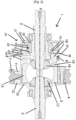
- the coupling device 6 comprises an actuator 24, illustrated in the Figures 1 to 3 , allowing the first coupling part 18 to be moved axially.
- the actuator 24 comprises a casing 25 which is intended to be mounted on the chassis of the vehicle, fixed in rotation relative to the latter, by means of fixing members not illustrated.
- the casing 25 comprises an internal skirt 26 which is fitted around a portion of the part 9 of the housing 8.
- the internal skirt 26 comprises a cylindrical guide portion which cooperates with a corresponding cylindrical portion of the housing 8 and thus allows the rotation of the housing 8 relative to the fixed casing 25 of the actuator 24.
- the actuator 24 is an electromagnetic actuator. It comprises an electromagnet 27 defining an internal housing and a piston 28 axially movable within the internal housing between a retracted position, illustrated in figure 2 , and a deployed position, illustrated on the figure 3
- the actuator 24 further comprises a magnetic cover 29 which closes the internal housing and which comprises a stop 30, such as a shoulder, for define the deployed position of the piston 28.
- the piston 28 comprises a body 31, of annular shape, made of ferromagnetic material, such as iron or steel for example.
- the piston 28 further comprises a paramagnetic tip 32, also of annular shape, which is fixed to the body 31 of the piston 28 and by which the actuating force is transmitted to the first coupling part 18.
- the paramagnetic tip 32 of the piston 28 thus makes it possible to avoid undesirable leaks of magnetic flux towards the other components of the coupling device 6. Furthermore, the body 31 of the piston 28 comprises a shoulder 33 intended to come into abutment against the shoulder 30 of the magnetic cover 29 when the piston 28 is in the deployed position.
- the electromagnet 27 When the electromagnet 27 is energized with an intensity greater than a threshold intensity, it allows the piston 28 to be moved from the retracted position, illustrated in the figure 2 , towards the deployed position, illustrated in the figure 3 . When the piston 28 is in the deployed position, the magnetic cover 29 exerts an attraction on the body 31 of the piston 28, which allows it to be maintained in the deployed position. The supply intensity of the electromagnet 27 can then be reduced as long as it remains greater than said threshold intensity.
- an elastic return means which returns the first coupling part 18 to the uncoupled position, makes it possible to overcome the force of attraction between the magnetic cover 29 and the body 31 of the piston 28 and to return the piston 28 from the deployed position to the retracted position.
- the coupling device 6 is also equipped with a target 34 which is fixed axially to the first coupling part 18. Furthermore, the coupling device 6 comprises a contactless sensor 35, shown in the figure 1 , which is positioned axially opposite the target 34 and which is configured to deliver a signal representative of the axial distance between the target 34 and the sensor 35. Thus, the sensor 35 is able to deliver a signal representative of the position of the first coupling part 18, such a signal being used to ensure the reliability of the control of the coupling device 6 and in particular to verify that the coupling device 6 is indeed in the uncoupled position or in the coupled position.
- the sensor 34 is for example a Hall effect sensor.
- the coupling device 6 comprises a disk 36, visible in its entirety on the figure 4 , which is formed in one piece and is fixed axially to the first coupling part 18.
- the disc 36 provides numerous functionalities described below and thus makes it possible to limit the cost, complexity and size of the coupling device 6.
- the disk 36 performs the function of target 34.
- the disk comprises an annular portion 37, formed at the radially external periphery of the disk 36. This annular portion 37 is arranged axially opposite the sensor 35 and thus forms the target 34.
- the disc 36 acts as an elastic return means for returning the first coupling part 18 to the uncoupled position when the piston 28 of the actuator 24 returns to the retracted position.
- the disk 36 comprises elastic blades 41, four in number in the embodiment shown.
- the elastic blades 41 each have a free end 42 which bears against a support zone of the housing 8 and a proximal end connected to the rest of the disk 36.
- the elastic blades 41 are each arranged in windows 43 positioned radially inside the annular portion 37.
- the elastic blades 41 extend circumferentially around the axis X, which makes it possible to obtain, for a given radial size, elastic blades 41 of greater length and, consequently, of lower stiffness.
- the free end 42 of the elastic blades 41 bears against the ends of studs 44 projecting axially from the housing 8 towards the disk 36.
- the studs 44 project by an axial dimension greater than the travel of the first coupling part 18 between the uncoupled position and the coupled position.
- the axial dimension of the studs 44 is such that, when the coupling device 6 is in the uncoupled position, the elastic blades 41 extend substantially in the plane of the annular portion 37 forming the target 34.
- the elastic blades 41 thus each form an elastic return portion which is configured to flex elastically during the movement of the first coupling part 18 from the uncoupled position to the coupled position. In reaction, the elastic blades 41 exert a return force capable of returning said first coupling part 18 to the uncoupled position.
- the disk 36 comprises a plurality of fixing tabs 38, visible on the figure 4 , also four in number in the embodiment shown.
- the fixing tabs 38 are circumferentially distributed around the axis X and each have a free end 39 defining a fixing zone which is fixed to the outer portion 21 of the first coupling part 18.
- the fixing tabs 37 are arranged in windows 40 formed in a portion of the disk 36 arranged radially inside the annular portion 37 forming a target 34. Each of the windows 40 associated with the tabs is thus arranged circumferentially between two windows 43 associated with the elastic blades.
- the fixing tabs 38 project radially inwards from a radially external edge of said windows 40. Furthermore, the tabs of the outer portion 21 pass through said windows 40.
- the legs of the outer portion 21 each have a groove in which the free end 39 of one of the fixing tabs 38 is clipped, which makes it possible to fix the disc 36 to the first coupling part 18, simply, without additional fixing member.
- the disk 36 also makes it possible to transmit the actuating force between the piston 28 of the actuator 24 and the first coupling part 18.
- the piston 28 of the actuator 24 is in contact against an internal annular portion 45 of the disk 36 which defines an actuating zone.
- the disk 36 is able to deform elastically between said actuating zone and the free ends 39 of the fixing tabs 38 when the piston 28 of the actuator 24 is moved from the retracted position to the deployed position. This makes it possible to compensate for the tolerances of the chain of dimensions of the coupling device 6 by ensuring that the piston 28 as well as the first coupling part 18 move over their entire stroke during their respective movement to the deployed position and the coupled position.
- the inner annular portion 45 of the disk 36 is spaced from a stop zone of the first coupling part 18 by an axial clearance 49 which is greater than the axial manufacturing tolerances of the coupling device 6.
- the axial clearance 49 is, for example, between 0.2 and 1.5 mm.
- the disk 36 and in particular its inner annular portion 45 deforms in order to catch up with axial manufacturing tolerances of the coupling device and then the inner annular portion 45 of the disk 36 comes into abutment against the stop zone of the first coupling part 18 when said axial manufacturing tolerances of the coupling device 6 have been caught up.
- the disk 36 has cutouts 46, notably shown in the figure 4 , extending circumferentially in an area positioned radially between the inner annular portion 45 of the disc 36 which defines the actuation zone and the windows 43.
- Such cutouts 46 are advantageous in that they further increase the flexibility of the disc 36.
- the disk 36 is sized to generate a stiffness K2 opposing an axial approach of the piston 28 of the actuator 24 towards the first coupling part 18 which is between 50 and 500 N/mm.
- the stiffness K2 is greater than the stiffness K1.
- the stiffness K2 is between 4*K1 and 20*K1.
- the disk 36 provides a sliding interface limiting the friction forces caused by the relative rotation of the disk 36, which is mobile in rotation about the axis X, relative to the piston 28 which is fixed in rotation.
- the annular portion 45 of the disk 36 comprises, on its face facing the piston 28, grooves 47 for the passage of oil, shown in FIG. figure 4 .
- the disk 36 is for example made of spring steel, such as XC 70 steel, advantageously pre-hardened.
- the disk 36 has a thickness of between 0.4 and 1.2 mm, for example of the order of 0.8 mm.
- the disk 36 is made of stainless steel.
- FIGS. 6 and 7 represent a coupling device 6 according to another embodiment.
- This coupling device 6 does not differ from that described above in relation to the Figures 1 to 5 than by the method of fixing the disk 36 to the first coupling part 18.
- the free end 39 of each of the fixing tabs 38 is fixed by a fixing member 48, such as a screw, to the outer portion 21 of the first coupling part 18, which makes it possible to ensure greater rigidity of the fixing of the disk 36 to the first coupling part 18.
Landscapes
- Engineering & Computer Science (AREA)
- General Engineering & Computer Science (AREA)
- Mechanical Engineering (AREA)
- Physics & Mathematics (AREA)
- Electromagnetism (AREA)
- Mechanical Operated Clutches (AREA)
- Connection Of Motors, Electrical Generators, Mechanical Devices, And The Like (AREA)
- Arrangement And Mounting Of Devices That Control Transmission Of Motive Force (AREA)
- Retarders (AREA)
Applications Claiming Priority (2)
| Application Number | Priority Date | Filing Date | Title |
|---|---|---|---|
| FR2102553A FR3120669B1 (fr) | 2021-03-15 | 2021-03-15 | Système de transmission équipé d’un dispositif d’accouplement |
| PCT/EP2022/056438 WO2022194729A1 (fr) | 2021-03-15 | 2022-03-14 | Système de transmission équipé d'un dispositif d'accouplement |
Publications (2)
| Publication Number | Publication Date |
|---|---|
| EP4308824A1 EP4308824A1 (fr) | 2024-01-24 |
| EP4308824B1 true EP4308824B1 (fr) | 2025-01-29 |
Family
ID=75746874
Family Applications (1)
| Application Number | Title | Priority Date | Filing Date |
|---|---|---|---|
| EP22712931.9A Active EP4308824B1 (fr) | 2021-03-15 | 2022-03-14 | Système de transmission équipé d'un dispositif d'accouplement |
Country Status (7)
| Country | Link |
|---|---|
| US (1) | US20240159278A1 (enExample) |
| EP (1) | EP4308824B1 (enExample) |
| JP (1) | JP7813809B2 (enExample) |
| KR (1) | KR20230145443A (enExample) |
| CN (1) | CN117242273A (enExample) |
| FR (1) | FR3120669B1 (enExample) |
| WO (1) | WO2022194729A1 (enExample) |
Families Citing this family (1)
| Publication number | Priority date | Publication date | Assignee | Title |
|---|---|---|---|---|
| FR3149061B1 (fr) * | 2023-05-23 | 2025-05-02 | Valeo Embrayages | Actionneur électromagnétique et système de transmission équipé d’un tel actionneur |
Family Cites Families (22)
| Publication number | Priority date | Publication date | Assignee | Title |
|---|---|---|---|---|
| US3973450A (en) * | 1975-03-24 | 1976-08-10 | Clark Equipment Company | Dynamic tooth clutch |
| JPS597715A (ja) * | 1982-07-07 | 1984-01-14 | Fuji Valve Kk | バルブ回転装置 |
| FR2679842A1 (fr) * | 1991-07-29 | 1993-02-05 | Shm Management Services Ag | Module de roulement moteur, notamment pour vehicule automobile. |
| DE19716386C2 (de) * | 1996-04-19 | 2002-10-31 | Tochigi Fuji Sangyo Kk | Ausgleichsgetriebe |
| JPH1016602A (ja) * | 1996-06-28 | 1998-01-20 | Tochigi Fuji Ind Co Ltd | ディファレンシャル装置 |
| US5989147A (en) * | 1998-02-25 | 1999-11-23 | Auburn Gear, Inc. | Electronically controllable limited slip differential |
| JP4262615B2 (ja) * | 2004-02-25 | 2009-05-13 | 日産自動車株式会社 | 電磁制御式差動制限装置 |
| JP4766962B2 (ja) * | 2005-09-02 | 2011-09-07 | Gknドライブラインジャパン株式会社 | デファレンシャル装置 |
| DE102005061268B4 (de) * | 2005-12-20 | 2007-09-27 | Gkn Driveline International Gmbh | Reibungskupplung mit Aktuator und Tellerfeder |
| JP2008057692A (ja) * | 2006-08-31 | 2008-03-13 | Gkn ドライブライン トルクテクノロジー株式会社 | スプリングの配置構造及びこれを用いたクラッチ装置 |
| JP2010084930A (ja) * | 2008-10-02 | 2010-04-15 | Gkn Driveline Japan Ltd | デファレンシャル装置 |
| JP5190887B2 (ja) * | 2008-12-17 | 2013-04-24 | カヤバ工業株式会社 | 附勢構造 |
| DE102013111891B4 (de) | 2013-10-29 | 2015-05-13 | Gkn Driveline International Gmbh | Antriebsanordnung mit einer Kupplung und Verfahren zur Montage einer solchen Antriebsanordnung |
| US10052950B2 (en) * | 2014-04-30 | 2018-08-21 | Gkn Automotive Ltd. | Selectable differential |
| DE102014215449B4 (de) * | 2014-08-05 | 2016-10-13 | Gkn Driveline International Gmbh | Kupplungsanordnung mit Sensoreinheit und Antriebsanordnung mit einer solchen Kupplungsanordnung |
| US9302581B1 (en) * | 2014-10-10 | 2016-04-05 | American Axle & Manufacturing, Inc. | All-wheel drive driveline with disconnecting axle |
| US10982744B2 (en) * | 2016-12-22 | 2021-04-20 | Gkn Automotive Limited | Electronically controlled differential locker |
| JP2019124261A (ja) * | 2018-01-12 | 2019-07-25 | 株式会社Subaru | 動力伝達装置 |
| JP2019158007A (ja) * | 2018-03-13 | 2019-09-19 | 株式会社ヴァレオジャパン | 電磁クラッチの組み付け体 |
| JP7035741B2 (ja) * | 2018-04-06 | 2022-03-15 | トヨタ自動車株式会社 | 連結装置を備えた車両 |
| FR3104209B1 (fr) * | 2019-12-05 | 2022-06-03 | MCE 5 Development | système hydraulique de commande pour un moteur à taux de compression variable |
| US11390160B2 (en) * | 2020-12-09 | 2022-07-19 | Ford Global Technologies, Llc | Wheel disconnect clutch |
-
2021
- 2021-03-15 FR FR2102553A patent/FR3120669B1/fr active Active
-
2022
- 2022-03-14 WO PCT/EP2022/056438 patent/WO2022194729A1/fr not_active Ceased
- 2022-03-14 EP EP22712931.9A patent/EP4308824B1/fr active Active
- 2022-03-14 JP JP2023556864A patent/JP7813809B2/ja active Active
- 2022-03-14 KR KR1020237031390A patent/KR20230145443A/ko not_active Ceased
- 2022-03-14 US US18/550,427 patent/US20240159278A1/en active Pending
- 2022-03-14 CN CN202280032519.0A patent/CN117242273A/zh active Pending
Also Published As
| Publication number | Publication date |
|---|---|
| KR20230145443A (ko) | 2023-10-17 |
| JP2024510248A (ja) | 2024-03-06 |
| WO2022194729A1 (fr) | 2022-09-22 |
| FR3120669A1 (fr) | 2022-09-16 |
| US20240159278A1 (en) | 2024-05-16 |
| EP4308824A1 (fr) | 2024-01-24 |
| JP7813809B2 (ja) | 2026-02-13 |
| CN117242273A (zh) | 2023-12-15 |
| FR3120669B1 (fr) | 2023-02-10 |
Similar Documents
| Publication | Publication Date | Title |
|---|---|---|
| FR2952689A1 (fr) | Differentiel a glissement limite avec dispositif de poussee dynamique | |
| EP4058853B1 (fr) | Mobile d'embrayage unidirectionnel, notamment pour l'horlogerie | |
| EP4308824B1 (fr) | Système de transmission équipé d'un dispositif d'accouplement | |
| EP0196966B1 (fr) | Butée de débrayage, notamment pour véhicule automobile | |
| FR3036450A1 (fr) | Transmission pour engin roulant a conducteur de preference marchant et engin roulant equipe d'une telle transmission | |
| FR2940773A1 (fr) | Dispositif de transmission pour engin roulant automoteur | |
| FR3009598A1 (fr) | Commande de vitesse a crabots pour boite de vitesses de vehicule | |
| EP4163517A1 (fr) | Système de transmission comportant un dispositif de réduction et un dispositif d'entraînement différentiel | |
| EP4356023A1 (fr) | Dispositif d'actionnement électromagnétique et système de transmission équipé de ce dispositif d'actionnement électromagnétique | |
| WO2002021021A1 (fr) | Appareil d'accouplement hydrocinetique, notamment pour vehicule automobile | |
| EP4448317A1 (fr) | Système de transmission comportant un dispositif d'entraînement différentiel | |
| FR2560329A1 (fr) | Dispositif amortisseur de torsion notamment pour disque de friction d'embrayage de vehicule automobile | |
| FR3074865B1 (fr) | Amortisseur de torsion a moyens de phasage | |
| FR3010752A1 (fr) | Commande de vitesse a crabots pour une boite de vitesses de vehicule | |
| EP4716807A1 (fr) | Actionneur électromagnétique et système de transmission équipé d'un tel actionneur | |
| FR3149062A1 (fr) | Système de transmission équipé d’un dispositif d’accouplement | |
| EP0926375B1 (fr) | Butée de débrayage avec agrafes latérales de guidage et de liaison | |
| EP3628884B1 (fr) | Sous-ensemble pour mecanisme d'embrayage et mecanisme d'embrayage comprenant un tel sous-ensemble | |
| EP3366940B1 (fr) | Disque d embrayage | |
| EP4457446A1 (fr) | Ensemble d'actionnement et actionneur pour groupe motopropulseur | |
| FR3159826A1 (fr) | Sous-ensemble d’accouplement pour différentiel de véhicule motorisé | |
| EP0320365A1 (fr) | Butée de débrayage actionnée par traction | |
| FR2638500A1 (fr) | Differentiel autobloquant a train epicycloidal | |
| EP4678446A1 (fr) | Module de différentiel | |
| EP4076818A1 (fr) | Ensemble de deux pieces concentriques emmanchées l'une dans l'autre, et procédé d'assemblage de ces deux pièces concentriques |
Legal Events
| Date | Code | Title | Description |
|---|---|---|---|
| STAA | Information on the status of an ep patent application or granted ep patent |
Free format text: STATUS: UNKNOWN |
|
| STAA | Information on the status of an ep patent application or granted ep patent |
Free format text: STATUS: THE INTERNATIONAL PUBLICATION HAS BEEN MADE |
|
| PUAI | Public reference made under article 153(3) epc to a published international application that has entered the european phase |
Free format text: ORIGINAL CODE: 0009012 |
|
| STAA | Information on the status of an ep patent application or granted ep patent |
Free format text: STATUS: REQUEST FOR EXAMINATION WAS MADE |
|
| 17P | Request for examination filed |
Effective date: 20230830 |
|
| AK | Designated contracting states |
Kind code of ref document: A1 Designated state(s): AL AT BE BG CH CY CZ DE DK EE ES FI FR GB GR HR HU IE IS IT LI LT LU LV MC MK MT NL NO PL PT RO RS SE SI SK SM TR |
|
| DAV | Request for validation of the european patent (deleted) | ||
| DAX | Request for extension of the european patent (deleted) | ||
| GRAP | Despatch of communication of intention to grant a patent |
Free format text: ORIGINAL CODE: EPIDOSNIGR1 |
|
| STAA | Information on the status of an ep patent application or granted ep patent |
Free format text: STATUS: GRANT OF PATENT IS INTENDED |
|
| INTG | Intention to grant announced |
Effective date: 20240903 |
|
| GRAS | Grant fee paid |
Free format text: ORIGINAL CODE: EPIDOSNIGR3 |
|
| GRAA | (expected) grant |
Free format text: ORIGINAL CODE: 0009210 |
|
| STAA | Information on the status of an ep patent application or granted ep patent |
Free format text: STATUS: THE PATENT HAS BEEN GRANTED |
|
| AK | Designated contracting states |
Kind code of ref document: B1 Designated state(s): AL AT BE BG CH CY CZ DE DK EE ES FI FR GB GR HR HU IE IS IT LI LT LU LV MC MK MT NL NO PL PT RO RS SE SI SK SM TR |
|
| REG | Reference to a national code |
Ref country code: GB Ref legal event code: FG4D Free format text: NOT ENGLISH |
|
| REG | Reference to a national code |
Ref country code: CH Ref legal event code: EP |
|
| REG | Reference to a national code |
Ref country code: DE Ref legal event code: R096 Ref document number: 602022010170 Country of ref document: DE |
|
| REG | Reference to a national code |
Ref country code: IE Ref legal event code: FG4D Free format text: LANGUAGE OF EP DOCUMENT: FRENCH |
|
| P01 | Opt-out of the competence of the unified patent court (upc) registered |
Free format text: CASE NUMBER: APP_16401/2025 Effective date: 20250404 |
|
| REG | Reference to a national code |
Ref country code: NL Ref legal event code: MP Effective date: 20250129 |
|
| PG25 | Lapsed in a contracting state [announced via postgrant information from national office to epo] |
Ref country code: NL Free format text: LAPSE BECAUSE OF FAILURE TO SUBMIT A TRANSLATION OF THE DESCRIPTION OR TO PAY THE FEE WITHIN THE PRESCRIBED TIME-LIMIT Effective date: 20250129 |
|
| PG25 | Lapsed in a contracting state [announced via postgrant information from national office to epo] |
Ref country code: RS Free format text: LAPSE BECAUSE OF FAILURE TO SUBMIT A TRANSLATION OF THE DESCRIPTION OR TO PAY THE FEE WITHIN THE PRESCRIBED TIME-LIMIT Effective date: 20250429 |
|
| PG25 | Lapsed in a contracting state [announced via postgrant information from national office to epo] |
Ref country code: FI Free format text: LAPSE BECAUSE OF FAILURE TO SUBMIT A TRANSLATION OF THE DESCRIPTION OR TO PAY THE FEE WITHIN THE PRESCRIBED TIME-LIMIT Effective date: 20250129 |
|
| PG25 | Lapsed in a contracting state [announced via postgrant information from national office to epo] |
Ref country code: PL Free format text: LAPSE BECAUSE OF FAILURE TO SUBMIT A TRANSLATION OF THE DESCRIPTION OR TO PAY THE FEE WITHIN THE PRESCRIBED TIME-LIMIT Effective date: 20250129 |
|
| PG25 | Lapsed in a contracting state [announced via postgrant information from national office to epo] |
Ref country code: ES Free format text: LAPSE BECAUSE OF FAILURE TO SUBMIT A TRANSLATION OF THE DESCRIPTION OR TO PAY THE FEE WITHIN THE PRESCRIBED TIME-LIMIT Effective date: 20250129 |
|
| REG | Reference to a national code |
Ref country code: LT Ref legal event code: MG9D |
|
| PG25 | Lapsed in a contracting state [announced via postgrant information from national office to epo] |
Ref country code: IS Free format text: LAPSE BECAUSE OF FAILURE TO SUBMIT A TRANSLATION OF THE DESCRIPTION OR TO PAY THE FEE WITHIN THE PRESCRIBED TIME-LIMIT Effective date: 20250529 Ref country code: NO Free format text: LAPSE BECAUSE OF FAILURE TO SUBMIT A TRANSLATION OF THE DESCRIPTION OR TO PAY THE FEE WITHIN THE PRESCRIBED TIME-LIMIT Effective date: 20250429 |
|
| PG25 | Lapsed in a contracting state [announced via postgrant information from national office to epo] |
Ref country code: HR Free format text: LAPSE BECAUSE OF FAILURE TO SUBMIT A TRANSLATION OF THE DESCRIPTION OR TO PAY THE FEE WITHIN THE PRESCRIBED TIME-LIMIT Effective date: 20250129 |
|
| PG25 | Lapsed in a contracting state [announced via postgrant information from national office to epo] |
Ref country code: LV Free format text: LAPSE BECAUSE OF FAILURE TO SUBMIT A TRANSLATION OF THE DESCRIPTION OR TO PAY THE FEE WITHIN THE PRESCRIBED TIME-LIMIT Effective date: 20250129 Ref country code: PT Free format text: LAPSE BECAUSE OF FAILURE TO SUBMIT A TRANSLATION OF THE DESCRIPTION OR TO PAY THE FEE WITHIN THE PRESCRIBED TIME-LIMIT Effective date: 20250529 |
|
| PG25 | Lapsed in a contracting state [announced via postgrant information from national office to epo] |
Ref country code: BG Free format text: LAPSE BECAUSE OF FAILURE TO SUBMIT A TRANSLATION OF THE DESCRIPTION OR TO PAY THE FEE WITHIN THE PRESCRIBED TIME-LIMIT Effective date: 20250129 Ref country code: GR Free format text: LAPSE BECAUSE OF FAILURE TO SUBMIT A TRANSLATION OF THE DESCRIPTION OR TO PAY THE FEE WITHIN THE PRESCRIBED TIME-LIMIT Effective date: 20250430 |
|
| PG25 | Lapsed in a contracting state [announced via postgrant information from national office to epo] |
Ref country code: SE Free format text: LAPSE BECAUSE OF FAILURE TO SUBMIT A TRANSLATION OF THE DESCRIPTION OR TO PAY THE FEE WITHIN THE PRESCRIBED TIME-LIMIT Effective date: 20250129 |
|
| PG25 | Lapsed in a contracting state [announced via postgrant information from national office to epo] |
Ref country code: SM Free format text: LAPSE BECAUSE OF FAILURE TO SUBMIT A TRANSLATION OF THE DESCRIPTION OR TO PAY THE FEE WITHIN THE PRESCRIBED TIME-LIMIT Effective date: 20250129 |
|
| PG25 | Lapsed in a contracting state [announced via postgrant information from national office to epo] |
Ref country code: DK Free format text: LAPSE BECAUSE OF FAILURE TO SUBMIT A TRANSLATION OF THE DESCRIPTION OR TO PAY THE FEE WITHIN THE PRESCRIBED TIME-LIMIT Effective date: 20250129 |
|
| PG25 | Lapsed in a contracting state [announced via postgrant information from national office to epo] |
Ref country code: MC Free format text: LAPSE BECAUSE OF FAILURE TO SUBMIT A TRANSLATION OF THE DESCRIPTION OR TO PAY THE FEE WITHIN THE PRESCRIBED TIME-LIMIT Effective date: 20250129 |
|
| PG25 | Lapsed in a contracting state [announced via postgrant information from national office to epo] |
Ref country code: CZ Free format text: LAPSE BECAUSE OF FAILURE TO SUBMIT A TRANSLATION OF THE DESCRIPTION OR TO PAY THE FEE WITHIN THE PRESCRIBED TIME-LIMIT Effective date: 20250129 Ref country code: EE Free format text: LAPSE BECAUSE OF FAILURE TO SUBMIT A TRANSLATION OF THE DESCRIPTION OR TO PAY THE FEE WITHIN THE PRESCRIBED TIME-LIMIT Effective date: 20250129 |
|
| PG25 | Lapsed in a contracting state [announced via postgrant information from national office to epo] |
Ref country code: RO Free format text: LAPSE BECAUSE OF FAILURE TO SUBMIT A TRANSLATION OF THE DESCRIPTION OR TO PAY THE FEE WITHIN THE PRESCRIBED TIME-LIMIT Effective date: 20250129 |
|
| REG | Reference to a national code |
Ref country code: CH Ref legal event code: H13 Free format text: ST27 STATUS EVENT CODE: U-0-0-H10-H13 (AS PROVIDED BY THE NATIONAL OFFICE) Effective date: 20251023 |
|
| PG25 | Lapsed in a contracting state [announced via postgrant information from national office to epo] |
Ref country code: SK Free format text: LAPSE BECAUSE OF FAILURE TO SUBMIT A TRANSLATION OF THE DESCRIPTION OR TO PAY THE FEE WITHIN THE PRESCRIBED TIME-LIMIT Effective date: 20250129 |
|
| REG | Reference to a national code |
Ref country code: DE Ref legal event code: R097 Ref document number: 602022010170 Country of ref document: DE |
|
| PG25 | Lapsed in a contracting state [announced via postgrant information from national office to epo] |
Ref country code: LU Free format text: LAPSE BECAUSE OF NON-PAYMENT OF DUE FEES Effective date: 20250314 |
|
| PLBE | No opposition filed within time limit |
Free format text: ORIGINAL CODE: 0009261 |
|
| STAA | Information on the status of an ep patent application or granted ep patent |
Free format text: STATUS: NO OPPOSITION FILED WITHIN TIME LIMIT |
|
| REG | Reference to a national code |
Ref country code: BE Ref legal event code: MM Effective date: 20250331 |
|
| 26N | No opposition filed |
Effective date: 20251030 |
|
| PG25 | Lapsed in a contracting state [announced via postgrant information from national office to epo] |
Ref country code: BE Free format text: LAPSE BECAUSE OF NON-PAYMENT OF DUE FEES Effective date: 20250331 |
|
| PG25 | Lapsed in a contracting state [announced via postgrant information from national office to epo] |
Ref country code: CH Free format text: LAPSE BECAUSE OF NON-PAYMENT OF DUE FEES Effective date: 20250331 |
|
| PG25 | Lapsed in a contracting state [announced via postgrant information from national office to epo] |
Ref country code: IE Free format text: LAPSE BECAUSE OF NON-PAYMENT OF DUE FEES Effective date: 20250314 |
|
| PGFP | Annual fee paid to national office [announced via postgrant information from national office to epo] |
Ref country code: DE Payment date: 20260313 Year of fee payment: 5 |
|
| PGFP | Annual fee paid to national office [announced via postgrant information from national office to epo] |
Ref country code: AT Payment date: 20260301 Year of fee payment: 5 |
|
| PGFP | Annual fee paid to national office [announced via postgrant information from national office to epo] |
Ref country code: IT Payment date: 20260309 Year of fee payment: 5 |
|
| PGFP | Annual fee paid to national office [announced via postgrant information from national office to epo] |
Ref country code: FR Payment date: 20260331 Year of fee payment: 5 |