EP4308449B1 - Zugsystem mit angebundenen flügeln mit einer vorrichtung zum greifen von falzlinien - Google Patents
Zugsystem mit angebundenen flügeln mit einer vorrichtung zum greifen von falzlinien Download PDFInfo
- Publication number
- EP4308449B1 EP4308449B1 EP22715610.6A EP22715610A EP4308449B1 EP 4308449 B1 EP4308449 B1 EP 4308449B1 EP 22715610 A EP22715610 A EP 22715610A EP 4308449 B1 EP4308449 B1 EP 4308449B1
- Authority
- EP
- European Patent Office
- Prior art keywords
- traction
- wing
- line
- folding
- traction system
- Prior art date
- Legal status (The legal status is an assumption and is not a legal conclusion. Google has not performed a legal analysis and makes no representation as to the accuracy of the status listed.)
- Active
Links
Images


Classifications
-
- B—PERFORMING OPERATIONS; TRANSPORTING
- B63—SHIPS OR OTHER WATERBORNE VESSELS; RELATED EQUIPMENT
- B63H—MARINE PROPULSION OR STEERING
- B63H9/00—Marine propulsion provided directly by wind power
- B63H9/04—Marine propulsion provided directly by wind power using sails or like wind-catching surfaces
- B63H9/06—Types of sail; Constructional features of sails; Arrangements thereof on vessels
- B63H9/069—Kite-sails for vessels
- B63H9/072—Control arrangements, e.g. for launching or recovery
-
- B—PERFORMING OPERATIONS; TRANSPORTING
- B63—SHIPS OR OTHER WATERBORNE VESSELS; RELATED EQUIPMENT
- B63B—SHIPS OR OTHER WATERBORNE VESSELS; EQUIPMENT FOR SHIPPING
- B63B35/00—Vessels or similar floating structures specially adapted for specific purposes and not otherwise provided for
- B63B2035/009—Wind propelled vessels comprising arrangements, installations or devices specially adapted therefor, other than wind propulsion arrangements, installations, or devices, such as sails, running rigging, or the like, and other than sailboards or the like or related equipment
-
- Y—GENERAL TAGGING OF NEW TECHNOLOGICAL DEVELOPMENTS; GENERAL TAGGING OF CROSS-SECTIONAL TECHNOLOGIES SPANNING OVER SEVERAL SECTIONS OF THE IPC; TECHNICAL SUBJECTS COVERED BY FORMER USPC CROSS-REFERENCE ART COLLECTIONS [XRACs] AND DIGESTS
- Y02—TECHNOLOGIES OR APPLICATIONS FOR MITIGATION OR ADAPTATION AGAINST CLIMATE CHANGE
- Y02T—CLIMATE CHANGE MITIGATION TECHNOLOGIES RELATED TO TRANSPORTATION
- Y02T70/00—Maritime or waterways transport
- Y02T70/50—Measures to reduce greenhouse gas emissions related to the propulsion system
- Y02T70/5218—Less carbon-intensive fuels, e.g. natural gas, biofuels
- Y02T70/5236—Renewable or hybrid-electric solutions
Definitions
- the invention relates to the field of captive wing traction systems which are adapted to deploy and fold a traction wing relative to a base platform, this traction wing being adapted to generate a traction force under the effect of the wind.
- Such traction systems allow the deployment of a flying traction wing used for the propulsion of a vehicle, in particular a ship (as the main mode of propulsion, or as an assistance), for the production of electricity, or for any application taking advantage of such traction force.
- the French patent application FR3082184 describes a captive wing traction system and a method of deploying and retracting the traction wing.
- the traction wing has fold lines attached to its leading edge, and the system includes means for pulling at least three fold lines to bring the leading edge against the mast at at least two different heights along the mast.
- This traction system benefits from a more efficient and safer deployment and retraction process.
- the invention aims to improve the captive wing traction systems of the prior art.
- the invention relates to a method for deploying or folding the traction wing of such a traction system, this method comprising a step of immobilizing the gripping device relative to the folding carriage, in a position where the hooking rod is opposite the gripping hook.
- Such a captive wing traction system benefits from automated capture of the folding lines with a high level of safety, regardless of external conditions such as weather, vehicle or ship movements, etc.
- Such a traction system can therefore be fully automated. Its deployment or retraction then requires no intervention from an operator.
- the gripping of the folding lines is indeed a critical point in the automation of such a system, because the attachment of these lines, which are by definition flexible and moving, is difficult and generally requires, in the prior art, human intervention to secure the gripping of the folding lines, for example using carabiner-type fasteners, or also requires complex and prominent immobilization devices which require the lines to be tensioned for automatic gripping.
- the invention makes it possible in particular to take advantage of the securing of the leading edge of the traction wing on the lashing mast (during the deployment or retraction phases) to safely implement the gripping and guidance of the folding lines regardless of their position and without constraining them.
- the invention makes it possible to fold the traction wing by arranging the folding lines vertically along the lashing mast, after gripping them using the gripping device, by simply sliding the folding carriage(s).
- the means for entering fold lines allow several fold lines to be entered simultaneously, while ensuring individual management of these fold lines. folding (or by pairs of folding lines) and bring them back sequentially along the mast following a single input operation.
- the traction system 1 is mounted at the bow of the vessel 2 and is operated as a supplementary means of propulsion of the vessel allowing fuel savings.
- the traction system 1 is sized according to the tonnage of the vessel to be towed and is intended to be deployed and folded automatically.
- this traction system 1 may be used for any other application where such an automatically deployable and foldable traction system is desired, for example as the primary means of propulsion of a ship, for the propulsion of any other vehicle, for the production of electricity, etc.
- the traction system 1 comprises a base platform 3 which is here fixed on the deck of the ship 2 and on which is mounted a mooring mast 4 provided for the automatic deployment and retraction operations of the system.
- the traction system 1 further comprises a traction wing 5 which is adapted to generate a traction force under the effect of the wind.
- the traction wing 5 is a paraglider-type sail. Any other flying equipment adapted to generate a traction force under the effect of the wind may alternatively be used, such as kites, gliding equipment, kite-type sails, etc.
- the traction wing 5 comprises, in a conventional manner, a leading edge 16 intended to be exposed to the incident wind and an opposite edge, called the trailing edge 17.
- the traction wing 5 is connected by a set of suspension lines 6 to a flight control device 7 which is adapted to act on the suspension lines 6 to control the flight of the traction wing 5.
- the traction system 1 further comprises a traction line 8 connecting the flight control device 7 to the base platform 3.
- the traction force generated by the traction wing 5 is transmitted by the traction line 8 to the ship 2 for its propulsion, and the traction line is dimensioned accordingly.
- the traction line can be, for example, a textile cable whose diameter can reach several centimeters.
- the flying trajectory control device 7 makes it possible to control the flight of the traction wing 5 in order to orient and position the traction wing and possibly to cause the traction wing 5 to describe flight figures making it possible to increase the traction force on the ship.
- the control of the trajectory of the traction wing 5 is here obtained by controlling the length of certain movable suspension lines, in a conventional manner in the field of flying wings.
- the set of suspension lines 6 in fact comprises fixed suspension lines (i.e. which have a fixed length between their attachment to the traction wing 5 and their attachment to the flying trajectory control device 7), and movable suspension lines whose length is variable.
- the flight control device 7 is thus adapted to pull on certain movable suspension lines and/or to release other movable suspension lines, so that the aerodynamic profile of the traction wing 5 is modified in order to control its lift, its trajectory, etc.
- the modification of the profile of a wing traction for controlling its trajectory is carried out in a conventional manner and will not be described in more detail here.
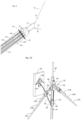
- the traction wing 5 further comprises a guide line 9 and several folding lines 10A, 10B, 10C which are all integral with the leading edge 16, by at least one of their ends.
- FIG. 2 is a profile view of the traction system 1 in the traction phase of the ship, as in the Figure 1 .
- FIG 2 further schematically illustrates the constituent elements of the traction system 1.
- the traction line 8 is connected to the base platform 3 by means of a winch 11 controlled by a motor, for example electric or hydraulic, adapted to unwind the traction line 8 to allow the traction wing 5 to gain altitude, or on the contrary to wind this traction line 8 to bring the traction wing 5 back to the base platform 3.
- a winch 11 controlled by a motor, for example electric or hydraulic, adapted to unwind the traction line 8 to allow the traction wing 5 to gain altitude, or on the contrary to wind this traction line 8 to bring the traction wing 5 back to the base platform 3.
- FIGS. 1 and 2 illustrate the traction system 1 in a traction configuration, with the traction wing 5 deployed and in flight, and the system participating in the propulsion of the vessel.
- the traction wing 5 has a furling line 13 which is divided into several lines (shown in dotted lines on the Figure 2 ) whose ends are connected to the trailing edge 17 of the wing 5.
- This furling line 13 can be grasped at the trailing edge 16 of the traction wing 5, and traction on this furling line 13 causes the wing 5 to be furled by compression in order to stow it.
- the traction system 1 comprises trolleys 12A, 12B, 12C, 12D, 12E, which are five in number in the present example. These trolleys are fixed in a sliding manner on the lashing mast 4 and each comprise a motorization so that the position of each trolley along the lashing mast 4 can be controlled. These trolleys are provided to grip and guide the folding lines 10A, 10B, 10C and the furling line 13 during the deployment or retraction phases described later.
- the traction system 1 comprises as many trolleys as necessary to grip the folding or furling lines, the number of which may vary from the example described.
- the fold lines 10A, 10B, 10C are arranged in pairs as shown in Figure 3 .
- the leading edge 16 of the traction wing 5 is, in the present description, divided into a median zone 15 and into two lateral edges 19 extending on either side of this median zone 15, between the median zone 15 and each of the lateral ends 18 of the leading edge 16.
- FIG. 3 also illustrates the path of the guide line 9 between the central portion 15 and the flight control device 7.
- the traction system 1 comprises a lashing line 20 which is wound onto a lashing winch 21 mounted on the base platform 3.
- the lashing line 20 starts from the winch 21 and is then guided into the lashing trolley 12B by one or more pulleys (or by low-friction elements, or any other element allowing the lashing line 20 to be slidably routed into the lashing trolley 12B).
- the lashing line 20 then passes into a shuttle 14 which is slidable along the guide line 9.
- the traction wing 5 can be folded according to the method described below.
- the winches 11 and 21 are first commanded to bring back the traction line 8 and the lashing line 20 so that the flying trajectory control device 7 comes to rest on the base platform 3, while the shuttle 14 rises along the guide line 9 as the traction wing 5 descends.
- the lashing line 20 passes into the lashing trolley 12B and holds the leading edge 16 by pulling against the lashing trolley 12B.
- the pulling wing 5 is then locked in this lashed position (as described later), the tension on the lashing line 20 is no longer necessary, and the gripping of the lines can take place.
- Line captures are made using hooks on the carriages, as well as a capture device, as explained later.
- the folding trolleys 12C, 12D, 12E then begin a downward movement along the lashing mast 4 by sliding their hooks along the lines that have been hooked.
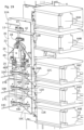
- FIG. 5 is a perspective view illustrating this operation of lowering the folding trolleys.
- Each of the folding trolleys 12C, 12D, 12E thus drives each of the folding lines progressively towards a configuration where the lines are stretched vertically from the middle zone 15 (which is secured to the lashing trolley 12B which remains fixed), along the lashing mast 4. This operation makes it possible to bring the lateral portions 19 vertically along the lashing mast 4.
- THE figures 6 (side view) and 7 (perspective view) illustrate the traction wing 5 after this folding operation, that is to say when the folding carriages 12C, 12D, 12E are each in their respective lower position.
- the traction wing 5 is then folded along the lashing mast 4, that is to say that the two lateral portions 19 of the leading edge 16 extend vertically along the lashing mast 4, while the middle zone 15 is kept lashed against the lashing trolley 12B.
- the wing 5 can then be furled.
- the furling carriage 12A (which has gripped the furling line 13) is then commanded to slide upwards along the lashing mast 4, and thus exerts traction on the furling line 13, which causes the furling of the traction wing 5.
- the furling is done by compression, by bringing the trailing edge 17 closer to the leading edge 16.
- the securing of the traction wing 5 relative to the securing trolley 12B is achieved by the cooperation of the securing line 20, the securing trolley 12B, the shuttle 14, and a gripping device 22.
- FIG 8 is a detail view of the Figure 3 , illustrating the traction wing 5 seen from the front and showing the middle zone 15, and the attachment of the folding lines 10A, 10B, 10C and the furling line 13 to the middle zone 15 of the leading edge 16, by means of the gripping device 22.
- the gripping device 22 is connected to the leading edge 16 of the traction wing 5, at the level of the median zone 15, by a pylon 23 (visible in particular on the side view of the Figure 12 ).
- the pylon 23 is thus named by analogy with the pylon of an aircraft, that is to say the reactor mast, in aeronautical terms.
- the pylon 23 is preferably made of a rib of light and resistant material such as a carbon fiber composite material.
- the pylon 23 is fixed on the gripping device 22 and on a reinforcement sewn on the leading edge 16 of the traction wing 5.
- the gripping device 22 may, alternatively, be connected by any other means, flexible or rigid, to the leading edge 16, such as textile ties or any other element making it possible to ensure that traction on the gripping device 22 causes traction on the leading edge 16.
- the gripping device 22 comprises a body 24 and two hooking arms 25, pivotally mounted on this body 24, each around an axis 26.
- Each of the hooking arms 25 comprises a first hooking rod 27A, a second hooking rod 27B of greater length, and a third hooking rod 27C of even greater length (the hooking rods 27A, 27B, 27C are seen in section on the figure 8 ).
- This arrangement in which the juxtaposed hanging rods have an increasing or decreasing length is here called "staircase".
- the hooking rods 27A, 27B, 27C are constituted by tubes force-fitted into bores provided for this purpose in the hooking arm 25.
- the attachment arms are movable relative to the body 24, between a flight position (that of the figure 8 ) and a hanging position (that of the figure 13 ) in which the attachment rods 27A, 27B, 27C are arranged substantially vertically (when the traction wing 5 is in its normal lashing position).
- Each hooking arm 25 further comprises a lever 28, that is to say a portion extending beyond the axis 26 and making it possible to act on the hooking arm 25 to fold it.
- Each fold line 10A, 10B, 10D, 10C which joins the middle zone 15 is connected to a hooking rod 27A, 27B, 27C so as to be projecting in the extension of this hooking rod.
- the end of the hooking rod is extended by the fold line.
- the folding line is advantageously inserted into the tube, crosses the entire tube, up to a fixing zone 29 of the hanging arm 25.
- FIG. 9 is a detailed view of the fixing zone 29.
- Each folding line 10A, 10B, 10C passes through the tube of the hanging rod 27A, 27B, 27C to open into the fixing zone 29.
- the end of each folding line 10A, 10B, 10C is held in place by a through pin 30 passing for example through a spliced eye 31 of the folding line 10A, 10B, 10C.
- the pivot connection between the hooking arms 25 and the body 24 allows the hooking arm 25 to naturally assume the spread position illustrated in figure 8 during the flight of the traction wing 5, the attachment arms 25 thus follow the opening dictated by the folding lines 10A, 10B, 10C which extend towards their other end connected further on the leading edge 16.
- the gripping device 22 may, in addition, comprise an elastic element (spring or other) urging the attachment arms 25 towards their flight position of the figure 8 .
- This flight position of the hooking arms 25 has the function of further securing the automatic hooking of the lines, by limiting the risks of tangling of the hooking arms 25 and the hooking rods 27A, 27B, 27C with the other lines such as the guide line 9 and the lashing line 20.
- Shuttle 14 is also shown in section on the figure 8 .
- the shuttle 14 has two sliding orifices 32, and is here oblong in shape with two flats. lateral 33.
- the oblong shape of the shuttle 14 allows guidance and angular orientation (around a horizontal axis) of the gripping device 22.
- the guide line 9 here consists of a pair of lines stretched between the body 24 and the flight control device 7.
- the pair of guide lines 9 forms a loop around a stop 34 of the body 24.
- the guide line 9 is thus attached to the middle zone 15 by means of the gripping device 22.
- the lashing line 20 passes through the shuttle 14 and is connected to the body 24.
- the shuttle 14 comprises a guide means crossed by the lashing line 20 and allowing the free sliding of the lashing line 20.
- this guide means is produced by a sheave 63 (see Figure 15 ) and can be alternatively achieved by any type of guiding means, such as pulleys or low-friction elements.
- the lashing line 20 thus extends from the lashing carriage 12B, crosses the shuttle 14 in a sliding manner, being guided towards the body 24.
- THE figures 10 And 11 illustrate the input device 22 in perspective from two different viewing angles.
- the face of the gripping device 22 which is visible is that which is turned towards the traction wing 5 (the yoke 23 not having been shown).
- the visible face of the gripping device 22 is that which is turned towards the lashing trolley 12B.
- the gripping device 22 is shown opposite a nesting interface 35 which is fixed to the lashing trolley 12B (the rest of the lashing trolley 12B has not been shown).
- the position of the figures 10 And 11 illustrates an intermediate position of the lashing operation of the traction wing 5 during its folding process.
- the traction line 8 has brought the traction wing 5 back so that its leading edge 16 is opposite the lashing trolley 12B, and the lashing line 20 is being wound by its winch 21, a traction then being exerted on the lashing line 20 (illustrated by the arrow of the Figure 11 ).
- the nesting interface 35 comprises elements allowing the gripping device 22 to be secured in a predefined position.
- these elements comprise a recess 39 which is complementary to a recess 40 of the body 24.
- the shuttle 14 is also part of these positioning elements, since it is designed to engage in an imprint 41 of the nesting interface 35.
- the recess 40 also has a significant advantage in terms of force absorption, since the cooperation of the recesses 39 and 40 makes it possible to absorb all of the vertical forces which will be exerted on the gripping device 22 during the folding operations, these forces possibly being greater than 15 kN.
- the imprint 41 comprises internal walls for receiving and positioning the shuttle 14.
- the coupling of the gripping device 22 and the nesting interface 35 is done in the predetermined position required by the nesting of the recesses 39, 40, and by the nesting of the shuttle 14 in the imprint 41.
- the ovoid shape of the shuttle 14 allows, during the lashing, to bring the gripping device 22 back to this predetermined position, even in the event of twisting of the lashing line 20, that is to say even in the event of rotation of the gripping device 22 around the lashing line 20.
- the convex shape of the shuttle 14 is thus adapted to be housed in a concave shape of the nesting interface 35, when the shuttle 14 is in the lashing configuration, the shuttle 14 causing if necessary the rotation of the assembly formed by the gripping device 22 and the shuttle 14, thanks to the shape ovoid of the shuttle 14, under the traction of the mooring line 20.
- FIG 14 illustrates an alternative embodiment for the nesting interface 35 in which the latter comprises a housing 44 complementary to the body 24 as well as inclined walls 45 intended to channel the trajectory of the gripping device 22 towards this housing 44, during the coupling phase of the gripping device 22 and the nesting interface 35.
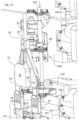
- FIG. 15 is a sectional view of the gripping device 22 (and the shuttle 14) after its coupling with the nesting interface 35.
- the leading edge 16 of the traction wing 5 is secured to the lashing trolley 12B by means of the gripping device 22. Maintaining a traction force on the lashing line 20 no longer causes the movement of the gripping device 22 (which is in abutment against the nesting interface) but maintains the lashing.
- FIG 16 illustrates the gripping device 22 thus secured to the lashing trolley 12B.
- This figure also illustrates the other trolleys 12A, 12C, 12D, 12E.
- Each of the trolleys can slide along the lashing mast 4, in a controlled manner, using actuators 64A, 64B, 64C, 64D, 64E.
- the actuators 64A, 64B, 64C, 64D, 64E are electric motors each controlling a pinion meshing with a rack fixed to the lashing mast 4 (the pinions and racks are not visible in the figures).
- the tie-down trolley 12B includes an upper immobilizing hook 48 and a pair of lower immobilizing hooks 49, which are movable between a retracted position, in which they are away from the gripping device 22, and an immobilization position (that shown in figure 16 ), in which they respectively block the body 24 and the hooking arms 25 against the nesting interface 35.
- Each of the folding carriages 12C, 12D, 12E comprises a pair of gripping hooks 46A, 46B, 46C, each of these pairs of gripping hooks being intended to hook the pair of folding lines 10A, 10B, 10C which corresponds to it.
- These hooks 12C, 12D, 12E are in the retracted position on the figure 16 .
- the furling trolley 12A has a gripping hook 47 intended to actuate the furling line 13 by the loop 55.
- the gripping hook 47 is also retracted on the figure 16 .
- Hooks 46A, 46B, 46C, 47, 48 are pivoting hooks in yokes secured to the corresponding carriage.
- the immobilizing hooks 48, 49 of the lashing trolley 12B are activated towards their immobilizing position to fix the gripping device 22 on the nesting interface 35, as illustrated in FIG. figure 16 . From this stage, the traction of the lashing line 20 is no longer necessary to maintain the lashing.
- the upper immobilizing hook 48 grips the upper part of the body 24 while the lower immobilizing hooks 49 grip the hooking arms 25, at the level of the fixing zone 29, that is to say above the hooking rods 27A, 27B, 27C.
- the activation of the hooks 48, 49 can be done by any means, such as for example a pivoting controlled by an electric motor, or remotely controlled magnetic actuation means.
- the actuation of the hooks 48, 49 is done thanks to the movement of the furling carriage 12A.
- the Figure 17 represents the carriages in transparency to make the mechanism visible.
- the hooks 48, 49 are each rotatably mounted on the carriage and can be actuated either by a shaft or by pinions.
- a control shaft 50 makes it possible to actuate in rotation all three hooks 48, 49, thanks to the arrangement of the pinions.
- the control shaft 50 has at its end a lug 51 adapted to cooperate with a helical cam path 52, integral with the furling carriage 12A, so that the approach of the furling carriage 12A towards the lashing carriage 12B causes the control shaft 50 to rotate, and therefore causes the hooks 48, 49 to their retracted position, and a move away of the furling carriage 12A from the lashing carriage 12B drives the hooks 48, 49 towards their immobilization position.
- An elastic element such as a torsion spring, biases the hooks 48, 49 towards their immobilization position.
- the same type of mechanism allows, when the furling carriage 12A continues to move away from the lashing carriage 12B, to also drive the furling hook 47 towards its gripping position, thanks to a control shaft 53 cooperating with a helical cam path 54.
- the gripping hooks 46A, 46B, 46C of the folding carriages 12C, 12D, 12E can also be controlled by any means allowing them to be closed on the hooking rods 27A, 27B, 27C.
- the passage of the gripping hooks 46A, 46B, 46C to their gripping position is preferably controlled by the distance of the corresponding folding carriage from the previous carriage, thanks to the same type of control as before, with control shaft, lug, and helical cam path.
- the furling trolley 12A is first slightly moved away from the lashing trolley 12B, which causes the immobilizing hooks 48, 49 to close and the gripping device 22 to be immobilized.
- the furling trolley 12A then remains in this position, the hook 47 being in the retracted position.
- the folding trolleys 12C, 12D, 12E then each begin a downward movement along the lashing mast 4, moving away from each other so that the pairs of hooks 46A, 46B, 46C close on the hooking rods 27A, 27B, 27C, as illustrated in figure 19 .
- Each hook 46A of the first folding carriage 12C closes on the three hooking rods 27A, 27B, 27C, that is to say just above the end of the first hooking rods 27A.
- Each hook 46B of the second folding carriage 12D closes on two hooking rods 27B, 27C, that is to say just above the end of the second hooking rods 27B.
- Each hook 46C of the third folding carriage 12E closes only on a third hooking rod 27C, just above the end of the third hooking rods 27C.
- Each of the pairs of folding hooks 46A, 46B, 46C is therefore in this position of the figure 19 , just above the exit of the fold lines 10A, 10B, 10C which correspond to it.
- the traction wing 5 can then be furled. This operation is carried out by raising the furling trolley 12A along the lashing mast 4, which first causes the furling hook 47 to close on the furling rod 42 (see figure 19 ). The continued rise of the 12A furling trolley then causes traction on loop 55 (loop 55 is visible at Figure 12 , and has not been shown in the other figures).
- the gripping device 22 thus makes it possible to guarantee rapid and secure lashing of the leading edge 16 of the traction wing 5 on the lashing trolley 12B, and also guarantees automatic, failure-free lashing of each of the folding lines 10A, 10B, 10C as well as the furling line 13.
- the lashing line 20 is not permanently attached to the body 24 and provides an additional function.
- the lashing line 20 passes through an orifice 56 made in the bottom wall 37 of the body 24 and is extended by an additional portion 62 in the direction of the traction wing 5. At its exit from the orifice 56, the lashing line 20 is fixed by a means clamping which here comprises jaws 57 held closed by elastic elements.
- the gripping device 22 thus comprises a clamping means adapted to occupy a clamping position in which the lashing line 20 is held fixed on the gripping device 22, and adapted to occupy a release position in which the lashing line 20 slides freely relative to the gripping device 20.
- the extension of the lashing line 20 beyond the jaws 57 allows this additional portion 62 of the lashing line 20 to perform an additional function within the traction wing 5.
- This function may for example relate to an action on the aerodynamic profile of the traction wing 5, or relate to an action of closing the trailing edge of the traction wing 5.
- This additional function is achieved by controlling the opening of the jaws 57 and by exerting traction on the lashing line 20, which causes traction on this additional portion 62 of the traction line 20 and therefore the achievement of this additional function, for example by traction modifying the shape of the trailing edge 17.
- the jaws 57 are controlled to open after the gripping device 22 has been immobilized by the immobilizing hooks 48, 49, so that the traction on the lashing line 20 is no longer useful for maintaining the lashing.
- FIG 21 illustrates an embodiment of the jaws 57 and their control (according to a schematic view similar to the figure 18 ).
- the jaws 57 are here associated with an opening lever 58 which allows the jaws 57 to be opened.
- the opening lever and the jaws 57 are urged by elastic elements towards their position corresponding to the tightening of the lashing line 20.
- the opening lever 58 is actuated by a rod 59 cooperating with a rod 60 having at its end a cam path 61.
- the rod 60 when pushed downwards by the approach of the furling carriage 12A, is designed to cause a retraction of the rod 59 (and therefore a release of the opening lever 58), which causes a closing of the jaws 57.
- the continued movement away of the furling carriage 12A from the lashing carriage 12B after having immobilized the gripping device, causes the opening of the jaws 57 and therefore the release of the additional portion 62 of the lashing line 20.
- the jaws 57 may be driven by any other means allowing the lashing line 20 to be detached from the gripping device 22 in order to perform an additional function within the traction wing 5.
- the method of deploying the traction wing 5, during the next use is then carried out according to the same operations as those described previously, executed in reverse order.
- the lines can be attached directly to the end of the hooking rods or the furling rod.
- the number of trolleys, hooks, and lines can of course vary to suit a particular application.
- clamping means which is here constituted by the jaws 57 can alternatively be produced by any other means of immobilizing a line in traction, for example by a textile sheath blocker.
Landscapes
- Engineering & Computer Science (AREA)
- Mechanical Engineering (AREA)
- Sustainable Development (AREA)
- Sustainable Energy (AREA)
- Chemical & Material Sciences (AREA)
- Combustion & Propulsion (AREA)
- Life Sciences & Earth Sciences (AREA)
- Ocean & Marine Engineering (AREA)
- Ship Loading And Unloading (AREA)
- Folding Of Thin Sheet-Like Materials, Special Discharging Devices, And Others (AREA)
- Handcart (AREA)
- Catching Or Destruction (AREA)
- Tents Or Canopies (AREA)
- Forklifts And Lifting Vehicles (AREA)
- Eye Examination Apparatus (AREA)
Claims (21)
- Schleppsystem mit angebundenem Schirm, welches aufweist:- einen Schleppschirm (5), der dazu eingerichtet ist, unter dem Einfluss von Wind eine Zugkraft zu erzeugen, wobei dieser Schleppschirm (5) eine Anströmkante (16) und eine Abströmkante (17) aufweist;- eine Basisplattform (3), mit der der Schleppschirm (5) über eine Schleppleine (8) verbunden ist, wobei der Schleppschirm (5) dazu eingerichtet ist, in Bezug auf diese Basisplattform (3) entfaltet und zusammengefaltet zu werden;- einen Befestigungsmast (4) für den Schleppschirm (5), der auf der Basisplattform (3) angeordnet ist;- mehrere Faltleinen (10A, 10B, 10C);wobei dieses Schleppsystem mit angebundenem Schirm aufweist:- einen Faltwagen (12C, 12D, 12E), der dazu eingerichtet ist, entlang des Befestigungsmastes (4) zu gleiten;eine Greifvorrichtung (22), die an der Anströmkante (16) des Schleppschirms (5) befestigt ist und die einen Anhängearm (25) umfasst, der mit einer Anhängestange (27A, 27B, 27C) ausgestattet ist, wobei eine der Faltleinen (10A, 10B, 10C) in der Verlängerung der Anhängestange (27A, 27B, 27C) vorstehend ist; wobei der Faltwagen (12C, 12D, 12E) einen Greifhaken (46A, 46B, 46C) aufweist, der zwischen einer zurückgezogenen Position und einer Greifposition, in welcher der Greifhaken (46A, 46B, 46C) die Anhängestange (27A, 27B, 27C) umgibt, beweglich ist, dadurch gekennzeichnet, dass die Faltleinen jeweils ein Ende aufweisen, das an der Anströmkante des Schleppschirms befestigt ist, wobei sie entlang dieser Anströmkante voneinander beabstandet sind.
- Schleppsystem nach Anspruch 1, dadurch gekennzeichnet, dass es eine Befestigungsleine (20) aufweist, welche die Greifvorrichtung (22) mit der Basisplattform (3) verbindet.
- Schleppsystem nach einem der vorhergehenden Ansprüche, dadurch gekennzeichnet, dass:- die Greifvorrichtung (22) an einem mittleren Bereich (15) der Anströmkante (16) befestigt ist;- die Faltleinen (10A, 10B, 10C) sich jeweils zwischen dem mittleren Bereich (15) und einem seitlichen Abschnitt (19) der Anströmkante (16) erstrecken;- die Faltleine (10A, 10B, 10C), die von der Anhängestange (27A, 27B, 27C) vorstehend ist, an ihrem entgegengesetzten Ende mit einem der seitlichen Abschnitte (19) verbunden ist.
- Schleppsystem nach einem der vorhergehenden Ansprüche, dadurch gekennzeichnet, dass die Greifvorrichtung (22) einen Körper (24) aufweist, an dem der Anhängearm (25) zwischen einer Flugposition und einer Anhängeposition, in welcher die Anhängestange (27A, 27B, 27C) im Wesentlichen vertikal angeordnet ist, schwenkbar angebracht ist.
- Schleppsystem nach einem der vorhergehenden Ansprüche, dadurch gekennzeichnet, dass die Anhängestange (27A, 27B, 27C) ein Rohr umfasst, das von der Faltleine (10A, 10B, 10C) durchquert wird, wobei diese Faltleine (10A, 10B, 10C) an ihrem Ende mit dem Anhängearm (25) verbunden ist.
- Schleppsystem nach einem der Ansprüche 2 bis 5, dadurch gekennzeichnet, dass es aufweist:- eine Führungsleine (9), welche die Greifvorrichtung (22) mit der fliegenden Vorrichtung zur Bahnsteuerung (7) verbindet;- einen entlang der Führungsleine (9) gleitenden Schlitten (14), wobei dieser Schlitten (14) ein Führungsmittel (63) umfasst, das von der Befestigungsleine (20) durchquert wird.
- Schleppsystem nach Anspruch 6, dadurch gekennzeichnet, dass die Greifvorrichtung (22) eine Aufnahme (36) für den Schlitten (14) aufweist, wobei der Schlitten (14) zwischen einer Gleitkonfiguration, in der er entlang der Führungsleine (9) gleitet, und einer Befestigungskonfiguration, in der der Schlitten (14) in seiner Aufnahme (36) angeordnet ist, beweglich ist.
- Schleppsystem nach Anspruch 7, wenn abhängig von Anspruch 4, dadurch gekennzeichnet, dass die Greifvorrichtung (22) einen Hebel (28) zur Steuerung der Schwenkung des Anhängearmes (25) zu seiner Anhängeposition hin aufweist, wobei dieser Hebel (28) dazu eingerichtet ist, von dem Schlitten (14) betätigt zu werden, wenn er in seine Befestigungskonfiguration zurückkehrt.
- Schleppsystem nach einem der vorhergehenden Ansprüche, dadurch gekennzeichnet, dass es einen Befestigungswagen (12B) umfasst, der dazu eingerichtet ist, entlang des Befestigungsmastes (4) zu gleiten, wobei dieser Befestigungswagen (12B) eine Aufnahmeschnittstelle (35) für die Greifvorrichtung (22) umfasst.
- Schleppsystem nach Anspruch 9, dadurch gekennzeichnet, dass der Befestigungswagen (12B) Mittel zum Arretieren der Greifvorrichtung (22) an der Aufnahmeschnittstelle (35) umfasst.
- Schleppsystem nach Anspruch 10, dadurch gekennzeichnet, dass die Arretiermittel einen Arretierhaken (48, 49) umfassen, der zwischen einer zurückgezogenen Position und einer Arretierposition, in welcher der Arretierhaken (48, 49) den Anhängearm (25) an der Aufnahmeschnittstelle (35) blockiert, beweglich ist.
- Schleppsystem nach einem der Ansprüche 10 oder 11, wenn abhängig von Anspruch 7, dadurch gekennzeichnet, dass der Schlitten (14) eine konvexe Form aufweist, die geeignet ist, in einer konkaven Form der Aufnahmeschnittstelle (35) aufgenommen zu werden, wenn sich der Schlitten (14) in der Befestigungskonfiguration befindet.
- Schleppsystem nach Anspruch 12, dadurch gekennzeichnet, dass der Schlitten (14) eine längliche Form aufweist.
- Schleppsystem nach einem der vorhergehenden Ansprüche, dadurch gekennzeichnet, dass:- die Faltleinen (10A, 10B, 10C) paarweise angeordnet sind, wobei die Faltleinen eines Paares die Greifvorrichtung (22) mit Punkten der Anströmkante (16) verbinden, die sich symmetrisch beiderseits der Greifvorrichtung (22) befinden;- die Greifvorrichtung zwei Anhängearme (25) aufweist, die jeweils mit ebenso vielen Anhängestangen (27A, 27B, 27C) ausgestattet sind, wie Paare von Faltleinen (10A, 10B, 10C) vorhanden sind.
- Schleppsystem nach Anspruch 14, dadurch gekennzeichnet, dass die Anhängestangen (27A, 27B, 27C) treppenförmig angeordnet sind.
- Schleppsystem nach einem der Ansprüche 14 oder 15, dadurch gekennzeichnet, dass es ebenso viele Faltwagen (12C, 12D, 12E) wie Paare von Faltleinen (10A, 10B, 10C) aufweist, wobei jeder Faltwagen (10A, 10B, 10C) ein Paar Greifhaken (46A, 46B, 46C) aufweist, die zwischen einer zurückgezogenen Position und einer Greifposition, in welcher die Greifhaken (46A, 46B, 46C) eines Paares die Anhängestangen (27A, 27B, 27C) der zwei Anhängearme (25) umgeben, beweglich sind.
- Schleppsystem nach einem der vorhergehenden Ansprüche, dadurch gekennzeichnet, dass:
der Schleppschirm (5) eine Festzurrleine (13) aufweist, die dazu eingerichtet ist, den Schleppschirm (5) festzuzurren;- die Greifvorrichtung (22) eine Festzurrstange (42) aufweist, wobei die Festzurrleine (13) in der Verlängerung der Festzurrstange (42) vorstehend ist;- das Schleppsystem einen Festzurrwagen (12A) aufweist, der dazu eingerichtet ist, entlang des Befestigungsmastes (4) zu gleiten, wobei der Festzurrwagen (12A) einen Festzurrhaken (47) aufweist, der zwischen einer zurückgezogenen Position und einer Greifposition, in welcher der Festzurrhaken (47) die Festzurrstange (42) umgibt, beweglich ist. - Schleppsystem nach einem der Ansprüche 2 bis 17, dadurch gekennzeichnet, dass die Greifvorrichtung (22) ein Spannmittel (57) aufweist, das dazu eingerichtet ist, eine Spannposition einzunehmen, in welcher die Befestigungsleine (20) fest an der Greifvorrichtung (22) gehalten wird, und dazu eingerichtet ist, eine Löseposition einzunehmen, in welcher die Befestigungsleine (20) bezüglich der Greifvorrichtung (20) frei gleitet.
- Schleppsystem nach Anspruch 18, dadurch gekennzeichnet, dass die Befestigungsleine (20) über die Greifvorrichtung (22) hinaus durch einen zusätzlichen Abschnitt (62) verlängert ist, der am Schleppschirm (5) befestigt ist, wobei die Befestigungsleine (20) dazu eingerichtet ist, eine zusätzliche Wirkung auf die Form des Schleppschirms (5) auszuüben, wenn sich das Spannmittel (57) in der Löseposition befindet.
- Schleppsystem nach einem der vorhergehenden Ansprüche, dadurch gekennzeichnet, dass der Greifhaken (46A, 46B, 46C) von einem Mechanismus gesteuert wird, der von einem weiteren Wagen betätigt wird, der dazu eingerichtet ist, entlang des Befestigungsmastes (4) zu gleiten.
- Verfahren zum Entfalten oder Zusammenfalten des Schleppschirms eines Schleppsystems nach einem der Ansprüche 1 bis 20, dadurch gekennzeichnet, dass es einen Schritt der Arretierung der Greifvorrichtung (22) bezüglich des Faltwagens (12C, 12D, 12E) in einer Position, in der sich die Anhängestange (27A, 27B, 27C) gegenüber dem Greifhaken (46A, 46B, 46C) befindet, umfasst.
Applications Claiming Priority (2)
| Application Number | Priority Date | Filing Date | Title |
|---|---|---|---|
| FR2102790A FR3120846B1 (fr) | 2021-03-19 | 2021-03-19 | Système de traction à aile captive avec dispositif de saisie des lignes de pliage |
| PCT/EP2022/056883 WO2022194963A1 (fr) | 2021-03-19 | 2022-03-16 | Systeme de traction a aile captive avec dispositif de saisie des lignes de pliage |
Publications (2)
| Publication Number | Publication Date |
|---|---|
| EP4308449A1 EP4308449A1 (de) | 2024-01-24 |
| EP4308449B1 true EP4308449B1 (de) | 2025-05-07 |
Family
ID=75539638
Family Applications (1)
| Application Number | Title | Priority Date | Filing Date |
|---|---|---|---|
| EP22715610.6A Active EP4308449B1 (de) | 2021-03-19 | 2022-03-16 | Zugsystem mit angebundenen flügeln mit einer vorrichtung zum greifen von falzlinien |
Country Status (9)
| Country | Link |
|---|---|
| US (1) | US20240166321A1 (de) |
| EP (1) | EP4308449B1 (de) |
| JP (1) | JP2024510152A (de) |
| KR (1) | KR20230157409A (de) |
| CN (1) | CN117062749A (de) |
| CA (1) | CA3211512A1 (de) |
| DK (1) | DK4308449T3 (de) |
| FR (1) | FR3120846B1 (de) |
| WO (1) | WO2022194963A1 (de) |
Families Citing this family (1)
| Publication number | Priority date | Publication date | Assignee | Title |
|---|---|---|---|---|
| FR3120845B1 (fr) * | 2021-03-19 | 2023-03-10 | Airseas | Système de traction à aile captive avec pliage en manche à air |
Family Cites Families (5)
| Publication number | Priority date | Publication date | Assignee | Title |
|---|---|---|---|---|
| DE102004018814A1 (de) * | 2004-04-19 | 2005-11-03 | Skysails Gmbh | Setzsystem für ein ausfliegendes drachenartiges Windangriffselement bei einem Wasserfahrzeug mit Windantrieb |
| PL2213568T3 (pl) * | 2006-08-15 | 2013-09-30 | Skysails Gmbh & Co Kg | Urządzenie do startu i zwijania przeznaczone do aerodynamicznego elementu profilowanego |
| CN103552668A (zh) * | 2013-11-19 | 2014-02-05 | 周振文 | 风帆飞船及与其配合使用的远海航行保障高速帆船 |
| PT3271575T (pt) * | 2015-03-20 | 2019-06-07 | Skypull Sagl | Dispositivo de ar de tração, dispositivo de ar para uma instalação eólica e instalação eólica para produção de energia elétrica, navio dotado de um dispositivo de ar de tração |
| FR3082184B1 (fr) | 2018-06-11 | 2020-07-03 | Airseas | Systeme comprenant une voile captive et un poste fixe avec des moyens de pliage de la voile au poste fixe |
-
2021
- 2021-03-19 FR FR2102790A patent/FR3120846B1/fr active Active
-
2022
- 2022-03-16 US US18/549,909 patent/US20240166321A1/en active Pending
- 2022-03-16 KR KR1020237034715A patent/KR20230157409A/ko active Pending
- 2022-03-16 WO PCT/EP2022/056883 patent/WO2022194963A1/fr not_active Ceased
- 2022-03-16 CN CN202280019424.5A patent/CN117062749A/zh active Pending
- 2022-03-16 DK DK22715610.6T patent/DK4308449T3/da active
- 2022-03-16 CA CA3211512A patent/CA3211512A1/fr active Pending
- 2022-03-16 EP EP22715610.6A patent/EP4308449B1/de active Active
- 2022-03-16 JP JP2023553991A patent/JP2024510152A/ja active Pending
Also Published As
| Publication number | Publication date |
|---|---|
| JP2024510152A (ja) | 2024-03-06 |
| WO2022194963A1 (fr) | 2022-09-22 |
| FR3120846B1 (fr) | 2023-12-29 |
| US20240166321A1 (en) | 2024-05-23 |
| FR3120846A1 (fr) | 2022-09-23 |
| CN117062749A (zh) | 2023-11-14 |
| DK4308449T3 (da) | 2025-08-18 |
| KR20230157409A (ko) | 2023-11-16 |
| CA3211512A1 (fr) | 2022-09-22 |
| EP4308449A1 (de) | 2024-01-24 |
Similar Documents
| Publication | Publication Date | Title |
|---|---|---|
| EP4308451B1 (de) | Schleppsystem mit gefangenem segel und fliegender festmachleine | |
| EP3814215B1 (de) | Ziehsystem mit mindestens zwei fesselsegeln mit einem mast versehen mit verschiedenen festmachmitteln, die jeweils einem segel zugeordnet sind | |
| EP0103519A1 (de) | Vorrichtung zum Manövrieren von Hubschraubern an Bord von Schiffen | |
| EP4308449B1 (de) | Zugsystem mit angebundenen flügeln mit einer vorrichtung zum greifen von falzlinien | |
| EP4308448B1 (de) | Schleppsystem mit gefangenem segel und verfahren zur bewegung der wagen | |
| EP0449702A1 (de) | Verfahranlage eines Körpers durch ein Hauptfahrwerk und wenigstens ein schwenkbares Rad getragen, wie ein Hubschrauber, zwischen einem Lande- und einem Hallenbereich | |
| WO2019202147A1 (fr) | Dispositif de recuperation et de stockage d'une grand voile apres affalage | |
| CA3211321A1 (fr) | Systeme de traction a aile captive avec pliage en manche a air | |
| EP0254619B1 (de) | Verfahren und Vorrichtung zur Handhabungshilfe einer schwimmenden Ladung | |
| EP4436871B1 (de) | Zugsystem mit einem windzugflügel ausgestattet mit einer grundplatte mit internen lagerraum | |
| HK40093052A (zh) | 具有用於夹持折叠绳的系留翼牵引系统 | |
| HK40093966A (zh) | 系留翼牵引系统及用於移动支架的方法 | |
| FR2544276A1 (fr) | Dispositif de manoeuvre du spinnaker d'un catamaran | |
| EP1765666A1 (de) | Vorrichtung zum verstauen und ausweiten eines frontsegels eines segelboots | |
| FR2698067A1 (fr) | Système perfectionné pour l'enroulement et la manÓoeuvre à distance d'un spinnaker. | |
| FR2581962A1 (fr) | Systeme atterrisseur pour ballon dirigeable | |
| FR3039504A1 (fr) | Dispositif de prise de ris sur une voile de bateau attachee a une bome | |
| FR2878823A1 (fr) | Dispositif emmagasineur de voile d'avant pour voilier |
Legal Events
| Date | Code | Title | Description |
|---|---|---|---|
| STAA | Information on the status of an ep patent application or granted ep patent |
Free format text: STATUS: UNKNOWN |
|
| STAA | Information on the status of an ep patent application or granted ep patent |
Free format text: STATUS: THE INTERNATIONAL PUBLICATION HAS BEEN MADE |
|
| PUAI | Public reference made under article 153(3) epc to a published international application that has entered the european phase |
Free format text: ORIGINAL CODE: 0009012 |
|
| STAA | Information on the status of an ep patent application or granted ep patent |
Free format text: STATUS: REQUEST FOR EXAMINATION WAS MADE |
|
| 17P | Request for examination filed |
Effective date: 20231019 |
|
| AK | Designated contracting states |
Kind code of ref document: A1 Designated state(s): AL AT BE BG CH CY CZ DE DK EE ES FI FR GB GR HR HU IE IS IT LI LT LU LV MC MK MT NL NO PL PT RO RS SE SI SK SM TR |
|
| DAV | Request for validation of the european patent (deleted) | ||
| DAX | Request for extension of the european patent (deleted) | ||
| GRAP | Despatch of communication of intention to grant a patent |
Free format text: ORIGINAL CODE: EPIDOSNIGR1 |
|
| STAA | Information on the status of an ep patent application or granted ep patent |
Free format text: STATUS: GRANT OF PATENT IS INTENDED |
|
| INTG | Intention to grant announced |
Effective date: 20240828 |
|
| 19U | Interruption of proceedings before grant |
Effective date: 20240214 |
|
| 19W | Proceedings resumed before grant after interruption of proceedings |
Effective date: 20241202 |
|
| RAP3 | Party data changed (applicant data changed or rights of an application transferred) |
Owner name: KAWASAKI KISEN KAISHA LTD |
|
| 111L | Licence recorded |
Designated state(s): AL AT BE BG CH CY CZ DE DK EE ES FI FR GB GR HR HU IE IS IT LT LU LV MC MK MT NL NO PL PT RO RS SE SI SK SM TR Name of requester: OCEANICWING S.A.S., FR Effective date: 20241202 |
|
| GRAS | Grant fee paid |
Free format text: ORIGINAL CODE: EPIDOSNIGR3 |
|
| GRAA | (expected) grant |
Free format text: ORIGINAL CODE: 0009210 |
|
| STAA | Information on the status of an ep patent application or granted ep patent |
Free format text: STATUS: THE PATENT HAS BEEN GRANTED |
|
| 111L | Licence recorded |
Designated state(s): AL AT BE BG CH CY CZ DE DK EE ES FI FR GB GR HR HU IE IS IT LT LU LV MC MK MT NL NO PL PT RO RS SE SI SK SM TR Name of requester: OCEANICWING S.A.S., FR Effective date: 20241202 |
|
| AK | Designated contracting states |
Kind code of ref document: B1 Designated state(s): AL AT BE BG CH CY CZ DE DK EE ES FI FR GB GR HR HU IE IS IT LI LT LU LV MC MK MT NL NO PL PT RO RS SE SI SK SM TR |
|
| REG | Reference to a national code |
Ref country code: GB Ref legal event code: FG4D Free format text: NOT ENGLISH |
|
| REG | Reference to a national code |
Ref country code: CH Ref legal event code: EP |
|
| REG | Reference to a national code |
Ref country code: DE Ref legal event code: R096 Ref document number: 602022014295 Country of ref document: DE |
|
| REG | Reference to a national code |
Ref country code: IE Ref legal event code: FG4D Free format text: LANGUAGE OF EP DOCUMENT: FRENCH |
|
| REG | Reference to a national code |
Ref country code: NL Ref legal event code: FP |
|
| REG | Reference to a national code |
Ref country code: DK Ref legal event code: T3 Effective date: 20250806 |
|
| PG25 | Lapsed in a contracting state [announced via postgrant information from national office to epo] |
Ref country code: FI Free format text: LAPSE BECAUSE OF FAILURE TO SUBMIT A TRANSLATION OF THE DESCRIPTION OR TO PAY THE FEE WITHIN THE PRESCRIBED TIME-LIMIT Effective date: 20250507 Ref country code: ES Free format text: LAPSE BECAUSE OF FAILURE TO SUBMIT A TRANSLATION OF THE DESCRIPTION OR TO PAY THE FEE WITHIN THE PRESCRIBED TIME-LIMIT Effective date: 20250507 Ref country code: PT Free format text: LAPSE BECAUSE OF FAILURE TO SUBMIT A TRANSLATION OF THE DESCRIPTION OR TO PAY THE FEE WITHIN THE PRESCRIBED TIME-LIMIT Effective date: 20250908 |
|
| REG | Reference to a national code |
Ref country code: LT Ref legal event code: MG9D |
|
| PG25 | Lapsed in a contracting state [announced via postgrant information from national office to epo] |
Ref country code: PL Free format text: LAPSE BECAUSE OF FAILURE TO SUBMIT A TRANSLATION OF THE DESCRIPTION OR TO PAY THE FEE WITHIN THE PRESCRIBED TIME-LIMIT Effective date: 20250507 |
|
| REG | Reference to a national code |
Ref country code: AT Ref legal event code: MK05 Ref document number: 1792227 Country of ref document: AT Kind code of ref document: T Effective date: 20250507 |
|
| PG25 | Lapsed in a contracting state [announced via postgrant information from national office to epo] |
Ref country code: BG Free format text: LAPSE BECAUSE OF FAILURE TO SUBMIT A TRANSLATION OF THE DESCRIPTION OR TO PAY THE FEE WITHIN THE PRESCRIBED TIME-LIMIT Effective date: 20250507 |
|
| PG25 | Lapsed in a contracting state [announced via postgrant information from national office to epo] |
Ref country code: HR Free format text: LAPSE BECAUSE OF FAILURE TO SUBMIT A TRANSLATION OF THE DESCRIPTION OR TO PAY THE FEE WITHIN THE PRESCRIBED TIME-LIMIT Effective date: 20250507 |
|
| PG25 | Lapsed in a contracting state [announced via postgrant information from national office to epo] |
Ref country code: AT Free format text: LAPSE BECAUSE OF FAILURE TO SUBMIT A TRANSLATION OF THE DESCRIPTION OR TO PAY THE FEE WITHIN THE PRESCRIBED TIME-LIMIT Effective date: 20250507 |
|
| PG25 | Lapsed in a contracting state [announced via postgrant information from national office to epo] |
Ref country code: RS Free format text: LAPSE BECAUSE OF FAILURE TO SUBMIT A TRANSLATION OF THE DESCRIPTION OR TO PAY THE FEE WITHIN THE PRESCRIBED TIME-LIMIT Effective date: 20250807 |
|
| PG25 | Lapsed in a contracting state [announced via postgrant information from national office to epo] |
Ref country code: IS Free format text: LAPSE BECAUSE OF FAILURE TO SUBMIT A TRANSLATION OF THE DESCRIPTION OR TO PAY THE FEE WITHIN THE PRESCRIBED TIME-LIMIT Effective date: 20250907 |
|
| PG25 | Lapsed in a contracting state [announced via postgrant information from national office to epo] |
Ref country code: LV Free format text: LAPSE BECAUSE OF FAILURE TO SUBMIT A TRANSLATION OF THE DESCRIPTION OR TO PAY THE FEE WITHIN THE PRESCRIBED TIME-LIMIT Effective date: 20250507 |
|
| REG | Reference to a national code |
Ref country code: GR Ref legal event code: EP Ref document number: 20250401576 Country of ref document: GR Effective date: 20251009 |
|
| PG25 | Lapsed in a contracting state [announced via postgrant information from national office to epo] |
Ref country code: SM Free format text: LAPSE BECAUSE OF FAILURE TO SUBMIT A TRANSLATION OF THE DESCRIPTION OR TO PAY THE FEE WITHIN THE PRESCRIBED TIME-LIMIT Effective date: 20250507 |
|
| PG25 | Lapsed in a contracting state [announced via postgrant information from national office to epo] |
Ref country code: CZ Free format text: LAPSE BECAUSE OF FAILURE TO SUBMIT A TRANSLATION OF THE DESCRIPTION OR TO PAY THE FEE WITHIN THE PRESCRIBED TIME-LIMIT Effective date: 20250507 |
|
| PG25 | Lapsed in a contracting state [announced via postgrant information from national office to epo] |
Ref country code: EE Free format text: LAPSE BECAUSE OF FAILURE TO SUBMIT A TRANSLATION OF THE DESCRIPTION OR TO PAY THE FEE WITHIN THE PRESCRIBED TIME-LIMIT Effective date: 20250507 |
|
| PG25 | Lapsed in a contracting state [announced via postgrant information from national office to epo] |
Ref country code: SK Free format text: LAPSE BECAUSE OF FAILURE TO SUBMIT A TRANSLATION OF THE DESCRIPTION OR TO PAY THE FEE WITHIN THE PRESCRIBED TIME-LIMIT Effective date: 20250507 |
|
| PG25 | Lapsed in a contracting state [announced via postgrant information from national office to epo] |
Ref country code: IT Free format text: LAPSE BECAUSE OF FAILURE TO SUBMIT A TRANSLATION OF THE DESCRIPTION OR TO PAY THE FEE WITHIN THE PRESCRIBED TIME-LIMIT Effective date: 20250507 |