EP4308451B1 - Schleppsystem mit gefangenem segel und fliegender festmachleine - Google Patents
Schleppsystem mit gefangenem segel und fliegender festmachleine Download PDFInfo
- Publication number
- EP4308451B1 EP4308451B1 EP22716225.2A EP22716225A EP4308451B1 EP 4308451 B1 EP4308451 B1 EP 4308451B1 EP 22716225 A EP22716225 A EP 22716225A EP 4308451 B1 EP4308451 B1 EP 4308451B1
- Authority
- EP
- European Patent Office
- Prior art keywords
- traction
- line
- wing
- stowage
- captive
- Prior art date
- Legal status (The legal status is an assumption and is not a legal conclusion. Google has not performed a legal analysis and makes no representation as to the accuracy of the status listed.)
- Active
Links
Images


Classifications
-
- B—PERFORMING OPERATIONS; TRANSPORTING
- B63—SHIPS OR OTHER WATERBORNE VESSELS; RELATED EQUIPMENT
- B63H—MARINE PROPULSION OR STEERING
- B63H9/00—Marine propulsion provided directly by wind power
- B63H9/04—Marine propulsion provided directly by wind power using sails or like wind-catching surfaces
- B63H9/06—Types of sail; Constructional features of sails; Arrangements thereof on vessels
- B63H9/069—Kite-sails for vessels
- B63H9/072—Control arrangements, e.g. for launching or recovery
-
- B—PERFORMING OPERATIONS; TRANSPORTING
- B63—SHIPS OR OTHER WATERBORNE VESSELS; RELATED EQUIPMENT
- B63B—SHIPS OR OTHER WATERBORNE VESSELS; EQUIPMENT FOR SHIPPING
- B63B35/00—Vessels or similar floating structures specially adapted for specific purposes and not otherwise provided for
- B63B2035/009—Wind propelled vessels comprising arrangements, installations or devices specially adapted therefor, other than wind propulsion arrangements, installations, or devices, such as sails, running rigging, or the like, and other than sailboards or the like or related equipment
-
- Y—GENERAL TAGGING OF NEW TECHNOLOGICAL DEVELOPMENTS; GENERAL TAGGING OF CROSS-SECTIONAL TECHNOLOGIES SPANNING OVER SEVERAL SECTIONS OF THE IPC; TECHNICAL SUBJECTS COVERED BY FORMER USPC CROSS-REFERENCE ART COLLECTIONS [XRACs] AND DIGESTS
- Y02—TECHNOLOGIES OR APPLICATIONS FOR MITIGATION OR ADAPTATION AGAINST CLIMATE CHANGE
- Y02T—CLIMATE CHANGE MITIGATION TECHNOLOGIES RELATED TO TRANSPORTATION
- Y02T70/00—Maritime or waterways transport
- Y02T70/50—Measures to reduce greenhouse gas emissions related to the propulsion system
- Y02T70/5218—Less carbon-intensive fuels, e.g. natural gas, biofuels
- Y02T70/5236—Renewable or hybrid-electric solutions
Definitions
- the invention relates to the field of captive wing traction systems which are adapted to deploy and fold a traction wing relative to a base platform, this traction wing being adapted to generate a traction force under the effect of the wind.
- Such captive wing traction systems thus allow the deployment of a flying traction wing used for the propulsion of a vehicle, in particular a ship (as the main mode of propulsion, or as assistance), for the production of electricity, or for any application benefiting from such traction force.
- the patent application US7866271 describes a deployment system for a flying wing-type device.
- This system comprises a telescopic mast equipped with an adapter at the masthead which is adapted to pivot about the longitudinal axis of the mast.
- a lifeline runs along the mast, projects from the adapter, and is slidably attached to the tow cable which holds the flying wing, at a deflection of the tow cable whose end is connected to the leading edge of the wing.
- the flying wing has an inflatable leading edge and the lifeline makes it possible in particular to bring this inflatable leading edge against inflation means provided in the mast head adapter, the latter having a shape complementary to the profile of the leading edge of the wing.
- the traction cable is wound by a winch to bring the wing back to the height of the mast.
- the lifeline which until then was stored near the winch during the flight phase, is then pulled using a recovery point trolley.
- a guide slides along the traction cable from the recovery point trolley to the leading edge of the wing and pulls the wing against the mast. The wing is then furled.
- the invention aims to improve the captive wing traction systems of the prior art.
- the lines in question whether they are suspension lines, the towing line, the guide line, or the lashing line, may be made up of any means allowing a flexible connection to be made, for example a rope, a textile and/or metal cable, etc.
- Such a captive wing traction system allows the deployment and retraction of any type of traction wing, including traction wings without an inflatable leading edge, which are simpler and more efficient.
- the entire system is thus simplified in conjunction with a modification of the deployment and retraction procedure.
- Such a captive wing traction system benefits from lashing means (formed in particular by the guide line and the lashing line) which allow the leading edge of the traction wing to be held by the return element, against the lashing mast.
- lashing means are implemented quickly and simply, without any handling of lines. Indeed, the system carries out all the operations of deploying or retracting the traction wing without the lashing of the wing requiring operations where lines are grasped and placed in attachment and traction means. These operations, necessary in the prior art, are tedious and difficult to automate. When they are automated, they are subject to untimely failures (in particular in difficult environments such as the propulsion of a ship in severe weather conditions).
- the invention guarantees fully automatic and trouble-free deployment and retraction procedures, even in the most difficult conditions, thanks to lashing means that only include engaged lines.
- the lashing means allow a constant link to be maintained between the traction wing and the base platform, without disturbing the flight of the traction wing.
- the guide line runs, in a similar manner to a suspension line, between the flight control device and the leading edge of the traction wing.
- the guide line is attached on the one hand to the flight control device and on the other hand to the leading edge of the traction wing, possibly by means of an intermediate piece.
- the guide line preferably has a sufficient length so as not to generate traction between the leading edge of the wing and the flight control device, so as not to disturb the work of the suspension lines during flight.
- the guide line does not disturb the flight of the wing excessively, since its mass and the drag generated are comparable to that of a suspension line and no disturbance resulting, for example, from kinking is to be expected.
- the stowed position allows the leading edge of the wing to be dynamically locked against the lashing mast, while the flight position allows the lashing line to be kept ready for use during flight, without the lashing line generating any force on the leading edge of the traction wing, despite its maximum length of several hundred meters, with the associated mass and drag.
- the flight control device is a mechanism designed to support both the forces of the towing line and the tensile forces of the suspension lines. During flight, almost all of the flying mass of the lashing line is supported by the flight control device, without influence on the shape of the wing. traction, nor on the ability of the flight control device to pilot the wing, nor on the movements of the traction line.
- the joint work of the lashing line and the guide line makes it possible to make independent, to a certain extent, the work of controlling the length of the towing line on the one hand, and the length of the lashing line on the other hand.
- the lashing line can be controlled to lock the leading edge of the wing, or on the contrary release it relative to the lashing mast at different heights on the lashing mast, regardless of whether the towing line is at a predetermined height or not, and it is not necessary to act on the length of the towing line to act on the lashing line.
- the operations of hoisting or lowering the towing wing can thus be carried out while benefiting from the possibility of securing the towing wing over the entire height of the towing mast, and of dynamically maintaining this securing during the movement of the towing wing along the towing mast.
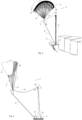
- FIG. 1 illustrates a captive wing traction system 1 mounted on a vessel 2 which is, in this example, a maritime cargo vessel (on the Figure 1 , only the front of the ship was shown).
- the captive wing traction system 1 is mounted at the bow of the vessel 2 and is operated as a supplementary means of propulsion of the vessel allowing fuel saving.
- the captive wing traction system 1 is dimensioned according to the tonnage of the vessel to be towed and is intended to be deployed and folded automatically.
- this captive wing traction system 1 may be used for any other application where such an automatically deployable and folding captive wing traction system is desired, for example as the primary means of propulsion of a ship, for propulsion of any other vehicle, for power generation, etc.
- the captive wing traction system 1 comprises a base platform 3 which is here fixed on the deck of the ship 2 and on which is mounted a lashing mast 4 provided for the automatic deployment and retraction operations of the system.
- the captive wing traction system 1 further comprises a traction wing 5 which is adapted to generate a traction force under the effect of the wind.
- the traction wing 5 is a paraglider-type sail. Any other flying equipment adapted to generate a traction force under the effect of the wind may alternatively be used, such as kites, gliding equipment, kite-type sails, etc.
- the traction wing 5 comprises, in a conventional manner, a leading edge 16 intended to be exposed to the incident wind and an opposite edge, called the trailing edge 17.
- the traction wing 5 is connected by a set of suspension lines 6 to a flight control device 7 which is adapted to act on the suspension lines 6 to control the flight of the traction wing 5.
- the captive wing traction system 1 further comprises a traction line 8 connecting the flight control device 7 to the base platform 3.
- the traction force generated by the wing 5 is transmitted by the traction line 8 to the ship 2 for its propulsion, and the traction line is dimensioned accordingly.
- the traction line can be, for example, a textile cable whose diameter can reach several centimeters.
- the flying trajectory control device 7 makes it possible to control the flight of the traction wing 5 in order to orient and position the traction wing and possibly to cause the traction wing 5 to describe flight figures making it possible to increase the traction force on the ship.
- the control of the trajectory of the traction wing 5 is here obtained by controlling the length of certain movable suspension lines, in a conventional manner in the field of flying wings.
- the set of suspension lines 6 in fact comprises fixed suspension lines (i.e. which have a fixed length between their attachment to the traction wing 5 and their attachment to the flying trajectory control device 7), and movable suspension lines whose length is variable.
- the flight control device 7 is thus adapted to pull on certain movable suspension lines and/or to release other movable suspension lines, so that the aerodynamic profile of the traction wing 5 is modified in order to control its lift, its trajectory, etc.
- the modification of the profile of a traction wing for the control of its trajectory is carried out in a conventional manner and will not be described in more detail here.
- the captive wing traction system 1 further comprises a guide line 9 which connects the leading edge 16 of the traction wing 5 to the flight control device 7, as well as a lashing line 10, one end of which is connected to the base platform 3 and the other end of which is slidably connected to the guide line 9. These two lines 9, 10 are used during the deployment and retraction phases of the traction wing 5.
- the guide line 9 has a lower end which is fixed to the flight control device 7 and has an upper end which is fixed to the leading edge 16 of the traction wing 5.
- the fixing between the guide line 9 and the leading edge 16 of the traction wing 5 can be carried out by any suitable means such as sewing the guide line 9 on the leading edge 16 of the traction wing 5.
- other fixing means in particular modular fixing means, can be provided to fix the guide line 9 to the leading edge 16 of the wing 5 (as in the second embodiment described below).
- FIG. 2 is a profile view of the captive wing traction system 1 in the ship's traction phase, as in the Figure 1 .
- FIG 2 further illustrates schematically the different constituent elements of the captive wing traction system 1.
- the traction line 8 is connected to the base platform 3 by means of a winch 11 controlled by a motor, for example electric or hydraulic, adapted to unwind the traction line 8 to allow the traction wing 5 to gain altitude, or on the contrary to wind this traction line 8 to bring the traction wing 5 back to the base platform 3.
- a winch 11 controlled by a motor, for example electric or hydraulic, adapted to unwind the traction line 8 to allow the traction wing 5 to gain altitude, or on the contrary to wind this traction line 8 to bring the traction wing 5 back to the base platform 3.
- the lashing line 10 is also connected to the base platform 3 by means of a winch 12 independent of the winch 11 of the traction line 8.
- the winches 12, 11 are however controlled in a coordinated manner.
- This lashing line 10 also runs via a return element 13 mounted on the lashing mast 4.
- the return element 13 is for example a pulley mounted on a lashing trolley 14, or a low-friction ring.
- the lashing trolley 14 slides vertically along the lashing mast 4, and comprises means for motorizing this movement.
- the end of the lashing line 10 is connected to the guide line 9 by a slider 15, which in the present example consists of an anti-friction ring fixed to the end of the lashing line 10, and in sliding pivot connection with the guide line 9.
- FIGS 1 and 2 illustrate the captive wing traction system 1 in a traction configuration, with the traction wing 5 deployed and in flight, and the system participating in the propulsion of the vessel.
- the slider 15 rests on the flight control device 7, under the effect of its own weight and the weight of the lashing line 10.
- the winch of the lashing line 10 is controlled so as to leave sufficient slack in the lashing line 10 to allow the slider 15 to rest on the flight control device 7.
- the length of the guide line 9 may also be provided with a certain amount of slack in all flight configurations of the traction wing 5, to prevent the guide line 9 from exerting, during flight, a pull on the leading edge 16 of the traction wing 5, so as not to disturb the flight of the traction wing 5.
- the guide line 9 may also act as a suspension and thus participate in absorbing the force of the canopy created by the traction wing, while ensuring that the forces due to the mass and drag of the mooring line 10 are not transmitted to the leading edge 16 of the traction wing 5.
- the flight control flying device 7 is provided on its upper face (i.e. its face facing the traction wing 5), with a receptacle adapted to receive and hold the slider 15 during the flight phases.
- the receptacle may consist of a base of the device 7 whose shape is adapted to hold the slider 15 in place, for example a flat resting surface, an imprint in which the slider 15 can be housed, or even a projecting finger of the device 7, which the ring constituting here the slider 15 comes to surround.
- This receptacle for the slider 15 may optionally comprise means for locking the slider 15 in this receptacle, during the flight phases.
- the winch 12 is also accordingly commanded to release the tie-down line 10 so that this tie-down line 10 retains its released character and does not interfere with the flight of the tow wing 5.
- neither the guide line 9 nor the tie-down line 10 act on the shape or trajectory of the tow wing 5.
- the figures 3 to 8 illustrate the successive steps allowing the folding of the traction wing 5.
- FIG. 3 is a view similar to the Figure 1 , the system being in a first approach phase initiating the folding of the traction wing 5.
- the winch 11 winds the traction line 8 so that the traction wing 5 is brought closer to the base platform 3.
- the winch 12 is simultaneously actuated to wind the lashing line 10.
- the traction wing 5 then reaches an altitude where the flying trajectory control device 7 is at an altitude close to that of the lashing trolley 14 (position illustrated Figure 3 and 4 ).
- the action of the winches 11, 12 is continued and causes the trajectory control flying device 7 to be lowered to an altitude lower than that of the return element 13, as shown in Figure 5 .
- the slider 15 then rises along the guide line 9, thanks to the free sliding permitted by the sliding pivot connection.
- the end of the lashing line 10 thus rises along the guide line 9 as the traction wing 5 approaches the base platform 3, until it reaches the position of the Figure 6 in which the flight control device 7 has reached a stop, for example on a support element secured to the base platform 3.
- the schematic view of the Figure 5 simply illustrates the flying trajectory control device 7 arranged against the base platform 3 (itself illustrated by a simple base) it being understood that, in practice, the base platform can be provided with any suitable receptacle to support and maintain the flying trajectory control device 7 when it is brought to its position of the Figure 5 .
- the height of the lashing mast 4 and the arrangement of the return element 13 are chosen so that, in the position of the Figure 6 , the slider 15 has reached the upper end of the guide line 9 and comes into abutment at the level of the leading edge 16 of the traction wing 5.
- a lashing operation consists of actuating the winch 12 alone to pull the lashing line 10, which causes the leading edge 16 of the traction wing 5 to move closer to a lashing position against the lashing trolley 14, a position illustrated in Figure 7 .
- the traction wing 5 is thus held by its leading edge 16 which is secured to the lashing mast 4.
- the lashing mast 4 and/or the lashing trolley 14 are pivoted around the longitudinal axis of the lashing mast 4, so that the traction wing 5 is secured to the mast facing the wind.
- the lashing mast 4 here comprises a rail 18 on which the lashing trolley 14 carrying the return element 13 is slidably mounted.
- Other trolleys 19 are also provided on this rail 18, in particular trolleys allowing the traction wing 5 to be folded efficiently by gripping it by folding lines connected along the traction wing 5 (not shown).
- These additional trolleys 19 are, for example, trolleys allowing the wing to be folded in two along the lashing mast 4, such as those described in the patent application WO2019239044 . All folding operations involving the additional trolleys 19 take place while the leading edge 16 of the traction wing 5 is held against the lashing mast 4 by the lashing line 10 and the guide line 9.
- the captive wing traction system 1 preferably comprises means for retaining the end of the lashing line 10 on the guide line 9. These retaining means are adapted to occupy: a free position in which the end of the lashing line 10 slides freely along the guide line 9; and a retaining position in which the end of the lashing line 10 is arranged in a loop formed by the guide line 9. These retaining means are here provided to retain the lashing line 10 on the guide line 9 when the slider 15 has reached the stop at the upper end of the guide line 9, that is to say in the position illustrated in Figure 6 .
- the docking operation which allows to pass from the position of the Figure 6 at the position of the Figure 7 can then be implemented without risk of the lashing line 10 slipping on the guide line 9.
- FIG. 9 is a schematic perspective view illustrating the end of the lashing line 10, provided with the slider 15, cooperating with the end of the guide line 9 which is located on the side of the traction wing 5.
- the guide line 9 is fixed by a ring 20 on a bar 21.
- the bar 21 is itself integral with the leading edge 16 of the traction wing 5 (for example by being inserted into a housing sewn onto the leading edge 16).
- the lashing trolley 14 comprises a locking member 22 pierced with a through channel 23 of a diameter adapted to the passage of the slider 15.
- the traction of the lashing line 10 ends up causing the slider 15 to pass through the through channel 23.
- the slider 15 carries with it the guide line 9 which also passes through the through channel 23 in a double passage.
- the locking member thus makes it possible to form a retention loop 36 for the slider 15 and therefore for the lashing line 10.
- FIG. 10 is a schematic sectional view of the elements of the Figure 9 after activation of its retention means during the lashing operation.
- the slider 15 has therefore crossed the channel 23 and the lashing line 10 has passed in duplicate in the channel 23, through the blocking member 22, forming the retention loop 36.
- the slack provided in the guide line 9 is here dimensioned to allow this double passage of the guide line 9 until the configuration of the Figure 10 in which the continuation of the traction on the lashing line 10 directly causes a traction on the bar 21, and the lashing line 10 is thus locked on the guide line 9.
- the deployment of the traction wing 5 is then carried out by operations taking place in the reverse order compared to the operations described previously, keeping the traction wing 5 facing the wind.
- the traction wing 5 When deploying the traction wing 5, the latter is held by its leading edge 16 against the lashing mast 4, to unfold it and prepare it for take-off. The traction wing 5 is then in a position corresponding to the Figures 7 and 8 , and the means for retaining the lashing line 10 on the guide line 9 are activated.
- the traction wing 5 is released by an operation making it pass from the position of the Figure 7 at the position of the Figure 6 , by releasing the lashing line 10 by its winch 12.
- the release of the lashing line 10 causes unlocking by the movement of the slider 15 which again passes through the locking member 22 in the direction of the guide line 9.
- the leading edge 16 then moves away from the lashing carriage 14.
- the traction wing 5 is then sent into flight by actuating the winches 11, 12 to release the traction line 8 and the lashing line 10.
- the traction wing then passes through a position corresponding to the Figure 5 , the slider 15 descending along the lashing line 10 as the traction wing 5 rises.
- the traction wing 5 then reaches its flight position of Figures 1 and 2 , the slider 15 taking place on its receptacle of the flying trajectory control device 7.
- THE figures 11 to 15 illustrate a second embodiment in which the captive wing traction system 1 comprises alternative means for fixing the guide line 9 to the leading edge 16 of the traction wing 5, as well as means for retaining the lashing line 10 on the guide line 9 which are complementary.
- the similar elements of the first and second embodiments bear the same reference numbers in the figures.
- the guide line 9 fulfills an additional function of controlling an additional line portion 24 which makes it possible to act on the geometry of the traction wing 5.
- the additional line portion 24 extends the guide line 9 beyond the leading edge 16 of the traction wing 5 by penetrating into the internal space of the traction wing 5, or by passing below or above the traction wing 5.
- This additional portion of line 24 may be, for example, a reefing line making it possible to reduce the lift of the traction wing 5, a furling line making it possible to furl the traction wing 5, or even a line bringing the trailing edges 17 together making it possible to close the trailing edge 17 by bringing its edges together, during the deployment or retraction phase.
- FIG. 11 schematically illustrates a construction in accordance with this second embodiment, with regard to the interface between the leading edge 16, the guide line 9, the lashing line 10, and the additional line portion 24.
- the guide line 9 is fixed to the leading edge 16 of the traction wing 5 by means of a disengageable clamping element 25 which here comprises a jaw 26.
- the disengageable clamping element 25 is fixed to the leading edge 16, for example by sewing on the traction wing 5, passing through the wall of the leading edge 16.
- the disengageable clamping element 25 comprises a sleeve 37, formed here by a bore passing right through it, and in which the guide line 9 passes.
- the jaw 26 is clamped by elastic means on the guide line 9 so that the guide line 9 is engaged on the leading edge 16, in the same manner as in the first embodiment.
- the remainder of the guide line 9 operates in the same manner as in the first embodiment, the slider 15 sliding along this guide line 9 as previously explained.
- FIG. 12 is a schematic side view of the captive wing traction system 1, for this second embodiment.
- This figure illustrates the disengageable clamping element 25 fixed on the leading edge 16 and immobilizing the guide line 9.
- the additional line portion 24 extends the guide line 9 beyond the leading edge 16, towards the inside of the traction wing 5.
- the additional line portion 24 is a line allowing the trailing edge 17 of the traction wing 5 to be closed.
- This additional line portion 24 is thus divided into several lines whose ends are fixed at various points 27 of the trailing edge 17, so that traction on the additional line portion 24 causes the trailing edge 17 to be closed by bringing together various portions of this trailing edge 17.
- the lashing trolley 14 in addition to carrying the return element 13, is adapted for coupling with the disengageable clamping element 25.
- the lashing trolley 14 comprises a locking member 22 whose function is the same as in the first embodiment (locking the lashing line 10 on the guide line 9) and which here also allows the disengageable clamping element 25 to be locked.
- FIG. 13 schematically illustrates in section the locking member which is mounted on the lashing trolley 14 in this second embodiment.
- the traction on the lashing line 10 causes, during the lashing phase, a double passage of the guide line 9 through the blocking member 22, and a coupling of the disengageable clamping element 25 in the blocking member 22.
- the disengageable clamping element 25 takes place in a housing 38 adapted to the blocking member 22.
- a tapered end 28 facilitates, in this example, the entry of the disengageable clamping element 25 into the housing 38.
- the lock 29 can be controlled by any suitable means, mechanical or electromagnetic for example.
- FIG. 13 is a schematic view illustrating the general operation.
- the locking member 22 and the clamping element 25 may be constituted by any coupling shape providing a passage, such as a groove, for the double passage of the guide line 9.
- this second embodiment also allows an additional function illustrated in Figures 14 and 15 .
- a step of disengaging the disengageable clamping element 25 consists of opening the jaws 26 by actuating the lever 31.
- the disengageable clamping element 25 thus releases the guide line 9 (position of the Figure 15 ).
- the traction of the lashing line 10 can then be continued by actuating the winch 12, which causes traction on the guide line 9.
- the traction on the guide line 9 causes traction on the additional line portion 24 which is therefore pulled in the direction of the return element 13, taking into account the opening of the jaws 26.
- FIGS. 14 and 15 account for the traction on the additional line portion 24 by the movement of the slider 15 towards the return element 13.
- These schematic views illustrate a small amplitude of movement of the slider 15, it being understood that the device will in practice be adapted to an amplitude conforming to the desired traction length for the additional line portion 24, in particular by the choice of the position of the return element 13, the capacity of the slider 15 to pass beyond the return element 13, or any other arrangement.
- FIG. 15 illustrates in this regard the traction wing 5 in a stowed position, held against the stowage mast 4 by its leading edge 16, and folded on either side of the stowage mast 4 thanks to the various additional carriages 19 which hold different suspension lines 6 or different dedicated folding lines.
- the traction of the additional line portion 24 makes it possible to fulfill its function of bringing the trailing edges 17 of the traction wing 5 together (illustrated by the arrows 34).
- the additional line portion 24 can, as a variant, fulfill any other function, for example a function of furling the traction wing 5 (illustrated by the arrows 33).
- the lashing line 10 When deploying traction wing 5, from the figure 16 , the lashing line 10 is first released by the winch 12 while the jaws 26 are controlled to open so that the additional line portion 24 is released and the traction wing 5 takes its flight shape, the traction wing 5 is then unfolded by means of the additional trolleys 19 while the traction wing 5 remains held against the lashing mast 4 thanks to the maintenance of the tension on the lashing line 10. The jaws 26 are closed, the additional line portion 24 having completed its task.
- the lashing line 10 is then released so that the traction wing 5 takes flight as described for the first embodiment.
- the captive wing traction system 1 benefits from a simplification of the lowering operations (concluding the folding of the traction wing 5), or of the hoisting operations (initiating the deployment of the traction wing 5). These operations are illustrated in figures 17 And 18 (the suspension lines have not been shown in these figures to make them lighter).
- the lowering of the traction wing 5 ends in the position of the figure 18 (where the housing 35 is seen in transparency).
- the traction wing 5 is entirely arranged in the housing 35, the winch 12 however maintaining, up to this position, the tension on the lashing line 10.
- the lashing trolley 14 is first hoisted along the lashing mast 4 while the winch 12 unwinds the lashing line 10 to accompany the raising of the lashing trolley 14, while maintaining a traction force on the lashing line 10 so that the lashing of the leading edge 16 is constantly maintained with the lashing trolley 14 throughout the hoisting operation of the traction wing 5.
- THE figures 19 to 25 relate to an embodiment in which the traction wing comprises a gripping device 122.
- the guide line 9 is a double line
- the traction wing 5 comprises several folding lines 110A, 110B, 110C which are all integral with the leading edge 16, by at least one of their ends.
- the traction wing 5 further comprises a furling line 113, the ends of which are connected to the trailing edge 17 of the wing 5.
- This furling line 113 can be grasped at the gripping device 122, and traction on this furling line 113 causes the wing 5 to be furled by compression in order to stow it.
- the traction system 1 comprises folding trolleys (such as the additional trolleys 19 of the figure 8 ). These trolleys are slidably fixed to the lashing mast 4 and each have a motor so that the position of each trolley along the lashing mast 4 can be controlled. These trolleys are designed to grip and guide the folding lines 110A, 110B, 110C and the furling line 113 during the deployment or retraction phases.
- the fold lines 110A, 110B, 110C are arranged in pairs as shown in figure 19 .
- FIG 19 is a detail view illustrating the traction wing 5 seen from the front and showing the middle zone 115 of its leading edge 16.
- the system here comprises a gripping device 122 which is connected to the leading edge 16 of the traction wing 5, at the level of the median zone 115, by a pylon 123 (visible in particular on the side view of the figure 22 ).
- the pylon 123 is thus named by analogy with the pylon of an aircraft, that is to say the reactor mast, in aeronautical terms.
- the pylon 123 is preferably made of a rib of light and resistant material such as a carbon fiber composite material.
- the pylon 123 is fixed on the gripping device 122 and on a reinforcement sewn on the leading edge 16 of the traction wing 5.
- the gripping device 122 may, alternatively, be connected by any other means, flexible or rigid, to the leading edge 16, such as textile ties or any other element making it possible to ensure that traction on the gripping device 122 causes traction on the leading edge 16.
- the gripping device 122 comprises a body 124 and two hooking arms 125, pivotally mounted on this body 124, each around an axis 126.
- Each of the hooking arms 125 comprises a first hooking rod 127A, a second hooking rod 127B of greater length, and a third hooking rod 127C of even greater length (the hooking rods 127A, 127B, 127C are seen in section on the figure 19 ).
- This arrangement in which the juxtaposed hanging rods have an increasing or decreasing length is here called "staircase”.
- the hooking rods 127A, 127B, 127C are constituted by tubes force-fitted into bores provided for this purpose in the hooking arm 125.
- the attachment arms are movable relative to the body 124, between a flight position (that of the figure 19 ) and a hanging position (that of the figure 23 ) in which the attachment rods 127A, 127B, 127C are arranged substantially vertically (when the traction wing 5 is in its normal lashing position).
- Each hooking arm 125 further comprises a lever 128, that is to say a portion extending beyond the axis 126 and making it possible to act on the hooking arm 125 to fold it.
- Each fold line 110A, 110B, 110D, 110C which joins the middle zone 115 is connected to a hooking rod 127A, 127B, 127C so as to be projecting in the extension of this hooking rod.
- the end of the hooking rod is extended by the fold line.
- the folding line is advantageously inserted into the tube, crosses the entire tube, up to a fixing zone 129 of the hanging arm 125.
- the pivot connection between the hooking arms 125 and the body 124 allows the hooking arm 125 to naturally assume the spread position illustrated in figure 19 during the flight of the traction wing 5, the attachment arms 125 thus following the opening dictated by the folding lines 110A, 110B, 110C which extend towards their other end connected further on the leading edge 16.
- the gripping device 122 may, in addition, comprise an elastic element (spring or other) urging the attachment arms 125 towards their flight position of the figure 19 .
- This flight position of the hooking arms 125 has the function of further securing the automatic hooking of the lines, by limiting the risks of tangling of the hooking arms 125 and the hooking rods 127A, 127B, 127C with the other lines such as the guide line 9 and the lashing line 10.
- the slider 15 comprises a shuttle 114 (also shown in section on the figure 19 ).
- the shuttle 114 has two sliding orifices 132, and is here oblong in shape with two lateral flats 133.
- the oblong shape of the shuttle 114 allows guidance and angular orientation (around a horizontal axis) of the gripping device 122.
- the guide line 9 here consists of a pair of lines stretched between the body 124 and the flight control device 7.
- the pair of guide lines 9 forms a loop around a stop 134 of the body 124.
- the guide line 9 is thus attached to the middle zone 115 by means of the gripping device 122.
- the lashing line 10 passes through the shuttle 114 and is connected to the body 124.
- the shuttle 114 comprises a guide means crossed by the lashing line 10 and allowing the free sliding of the lashing line 10.
- this guide means is produced by a sheave 63 (see figure 24 ) and can be alternatively realized by any type of guiding means, such as pulleys or low friction elements.
- the lashing line 10 thus extends from the lashing trolley 14, crosses the shuttle 114 in a sliding manner, being guided towards the body 124.
- THE figures 20 and 21 illustrate the input device 122 in perspective from two different viewing angles.
- the face of the gripping device 122 which is visible is that which is turned towards the traction wing 5 (the pylon 123 not having been shown).
- the visible face of the gripping device 122 is the one which is turned towards the lashing trolley 14.
- the gripping device 122 is shown opposite a nesting interface 135 which is fixed to the lashing trolley 14 (the rest of the lashing trolley 14 has not been shown).
- the position of the figures 20 and 21 illustrates an intermediate position of the lashing operation of the traction wing 5 during its folding process.
- the traction line 8 has brought the traction wing 5 back so that its leading edge 16 is opposite the lashing trolley 14, and the lashing line 10 is being wound up by its winch 12, a traction then being exerted on the lashing line 10.
- This operation causes the shuttle 114 to rise along the guide line 9. Doubling the guide line 9 here allows the shuttle 114 to slide without pivoting around a vertical axis. A sliding connection is thus ensured, instead of a sliding pivot connection.
- the gripping device 122 comprises, at the level of the body 124, a housing 136 intended to receive the shuttle 114.
- the housing 136 is delimited by side walls cooperating with the two flats 133 of the shuttle 114, and by a bottom wall 137 itself cooperating with another flat 138 of the shuttle 114.
- the nesting interface 135 comprises elements allowing the gripping device 122 to be secured in a predefined position.
- these elements comprise a recess 139 which is complementary to a recess 140 of the body 124.
- the shuttle 114 is also part of these positioning elements, since it is designed to engage in an imprint 141 of the nesting interface 135.
- the recess 140 also has a significant advantage in terms of force absorption, since the cooperation of the recesses 139 and 140 makes it possible to absorb all of the vertical forces which will be exerted on the gripping device 122 during the folding operations, these forces possibly being greater than 15 kN.
- the imprint 141 comprises internal walls for receiving and positioning the shuttle 114.
- the gripping device 122 comprises a furling rod 142 projecting vertically from above the body 124.
- the furling line 113 projects in the extension of the furling rod 124.
- the furling rod 142 is produced by a tube fitted into the body 124, the furling line passing through this tube and its end being fixed to the body 124.
- the furling line 113 Between its attachment to the furling rod 142 and its path towards the trailing edge 17, the furling line 113 forms a loop 155 and passes through a ring 143 which is integral with the tube 142.
- the ring 143 is for example a low-friction ring, or can be made by a tube or a pulley. A pull on the loop 55 thus causes a pull on the furling line 113 and therefore the furling of the traction wing 5.
- the traction on the lashing line 10, during the lashing phase of the traction wing 5, causes the shuttle 114 to rise and ends with the shuttle 114 entering the housing 136, as illustrated in figure 23 .
- Shuttle 114 is then immobilized in the housing 136, thanks to the dimensional adjustment allowing the plane-on-plane support of the flats 133, 138 against internal surfaces of the housing 136.
- the shuttle 114 is thus movable between a sliding configuration in which it slides along the guide line 9, and a docking configuration in which the shuttle 114 is arranged in its housing 136.
- the entry of the shuttle 114 into the housing 136 further activates the levers 128, which causes the closing of the hooking arms 125, that is to say their passage into the vertical position, and their maintenance in this position by the presence of the shuttle 114.
- the coupling of the gripping device 122 and the nesting interface 135 is done in the predetermined position required by the nesting of the recesses 139, 140, and by the nesting of the shuttle 114 in the imprint 141.
- the ovoid shape of the shuttle 114 allows, during the lashing, to bring the gripping device 122 back to this predetermined position, even in the event of twisting of the lashing line 10, that is to say even in the event of rotation of the gripping device 122 around the lashing line 10.
- the convex shape of the shuttle 114 is thus adapted to be housed in a concave shape of the nesting interface 135, when the shuttle 114 is in the lashing configuration, the shuttle 114 causing if necessary the rotation of the assembly formed by the gripping device 122 and the shuttle 114, thanks to the ovoid shape of the shuttle 114, under the traction of the lashing line 10.
- FIG 24 is a sectional view of the gripping device 122 (and the shuttle 114) after its coupling with the nesting interface 135.
- the leading edge 16 of the traction wing 5 is secured to the lashing trolley 14 by means of the gripping device 122. Maintaining a traction force on the lashing line 10 no longer causes the movement of the gripping device 122 (which is in abutment against the nesting interface) but maintains the lashing.
- the system further comprises immobilization means (not shown) movable between a retracted position, in which they are away from the gripping device 122, and an immobilization position in which they block the gripping device 122 against the nesting interface 135.
- the immobilization means are activated towards their immobilization position to fix the gripping device 122 on the nesting interface. 135. From this stage, traction of the lashing line 10 is no longer necessary to maintain the lashing.
- the lashing line 10 is not permanently attached to the body 124 and makes it possible to provide an additional function.
- the lashing line 10 passes through an orifice 156 made in the bottom wall 137 of the body 124 and is extended by an additional portion 162 in the direction of the traction wing 5. At its exit from the orifice 156, the lashing line 10 is fixed by a clamping means which here comprises jaws 157 kept closed by elastic elements.
- the gripping device 122 thus comprises a clamping means adapted to occupy a clamping position in which the lashing line 10 is held fixed on the gripping device 122, and adapted to occupy a release position in which the lashing line 10 slides freely relative to the gripping device 10.
- the extension of the lashing line 10 beyond the jaws 157 allows this additional portion 162 of the lashing line 10 to perform an additional function within the traction wing 5.
- This function may for example relate to an action on the aerodynamic profile of the traction wing 5, or relate to an action of closing the trailing edge of the traction wing 5.
- This additional function is achieved by controlling the opening of the jaws 157 and by exerting traction on the lashing line 10, which causes traction on this additional portion 162 of the traction line 10 and therefore the achievement of this additional function, for example by traction modifying the shape of the trailing edge 17.
- the jaws 157 are commanded to open after the gripping device 122 has been immobilized so that traction on the lashing line 10 is no longer useful for maintaining the lashing.
- FIG 26 illustrates an example of a receptacle adapted to receive the slider 15 during the flight phases.
- This receptacle 101 is fixed on the upper face 100 of the flying trajectory control device 7.
- the receptacle 101 is here formed of a cylindrical housing adapted to the shape of the slider 15, which comprises in the present example a shuttle 114 similar to that of the previous embodiment, with a double guide line 9.
- a shuttle 114 similar to that of the previous embodiment
- locking means are provided to immobilize the lashing line 10 and the slider 15 in the receptacle 101.
- these means are passive and consist of a line blocker 102 comprising elastic means bringing two jaws together.
- a line blocker 102 comprising elastic means bringing two jaws together.
- these locking means may be active, and consist for example of a controlled actuator capable of directly locking the slider 5 in its receptacle, or the lashing line.
- the lashing line 10 rests entirely, and securely, on the flying trajectory control device 7.
- the weight and drag of the lashing line 10 thus do not disturb the leading edge 16 of the traction wing 5 during the flight phases.
Landscapes
- Engineering & Computer Science (AREA)
- Mechanical Engineering (AREA)
- Sustainable Development (AREA)
- Sustainable Energy (AREA)
- Chemical & Material Sciences (AREA)
- Combustion & Propulsion (AREA)
- Life Sciences & Earth Sciences (AREA)
- Ocean & Marine Engineering (AREA)
- Ship Loading And Unloading (AREA)
- Transmission Devices (AREA)
- Toys (AREA)
- Control Of Position, Course, Altitude, Or Attitude Of Moving Bodies (AREA)
- Catching Or Destruction (AREA)
- Wind Motors (AREA)
Claims (25)
- Zugsystem mit angebundenem Schirm (1), umfassend einen Zugschirm (5), der dazu angepasst ist, unter dem Einfluss des Windes eine Zugkraft zu erzeugen, und dazu angepasst ist, in Bezug auf eine Basisplattform (3), die über einen Befestigungsmast (4) verfügt, auseinandergefaltet und zusammengefaltet zu werden, wobei der Zugschirm (5) eine Anströmkante (16) und eine Abströmkante (17) aufweist, wobei dieses Zugsystem mit angebundenem Schirm ferner Folgendes umfasst:- eine fliegende Vorrichtung zur Bahnsteuerung (7), die durch feste Hängeleinen (6) und bewegliche Hängeleinen (6) an dem Zugschirm (5) angebracht ist, wobei die fliegende Vorrichtung zur Bahnsteuerung (7) dazu angepasst ist, die beweglichen Hängeleinen (6) zu steuern;- eine Zugleine (8), die die fliegende Vorrichtung zur Bahnsteuerung (7) mit der Basisplattform (3) verbindet;wobei dieses Zugsystem mit angebundenem Schirm dadurch gekennzeichnet ist, dass es Folgendes umfasst:- eine Führungsleine (9), die die Anströmkante (16) des Zugschirms (5) mit der fliegenden Vorrichtung zur Bahnsteuerung (7) verbindet;- eine Befestigungsleine (10), von der eines der Enden mit der Basisplattform (3) verbunden ist und die durch ein Gleitstück (15), das an der Befestigungsleine (10) fixiert ist und mit der Führungsleine (9) in gleitender Gelenkverbindung steht, an der Führungsleine (9) angebracht ist;- ein Umlenkelement (13), das an dem Befestigungsmast (4) angebracht ist und über das die Befestigungsleine (10) zwischen ihrem ersten Ende und ihrer Anbringung an der Führungsleine (9) verläuft.
- Zugsystem mit angebundenem Schirm nach Anspruch 1, dadurch gekennzeichnet, dass das Gleitstück (15) einen Schlitten (114) umfasst, der entlang der Führungsleine (9) gleitet, wobei dieser Schlitten (114) ein Führungsmittel (63) umfasst, das von der Befestigungsleine (10) durchquert wird.
- Zugsystem mit angebundenem Schirm nach Anspruch 2, dadurch gekennzeichnet, dass die Führungsleine (9) aus einer Doppelleine besteht und dass der Schlitten (114) an dieser Doppelleine gleitend montiert ist.
- Zugsystem mit angebundenem Schirm nach einem der Ansprüche 2 bis 3, dadurch gekennzeichnet, dass die fliegende Vorrichtung zur Bahnsteuerung (7) einen Behälter (101) umfasst, der dazu angepasst ist, das Gleitstück (15) aufzunehmen, wobei dieser Behälter (101) ein Klemmstück (102) für die Befestigungsleine (10) umfasst.
- Zugsystem mit angebundenem Schirm nach einem der vorhergehenden Ansprüche, dadurch gekennzeichnet, dass die Zugleine (8) mit Hilfe einer ersten Winde (11), die dazu angepasst ist, die Länge der Zugleine (8) anzupassen, an der Basisplattform (3) angebracht ist und dass die Befestigungsleine (10) mit Hilfe einer zweiten Winde (12), die dazu angepasst ist, die Länge der Befestigungsleine (10) anzupassen, an der Basisplattform (3) angebracht ist.
- Zugsystem mit angebundenem Schirm nach einem der vorhergehenden Ansprüche, dadurch gekennzeichnet, dass das Umlenkelement (13) an einem Befestigungswagen (14) montiert ist, der entlang des Befestigungsmasts (4) gleitet.
- Zugsystem mit angebundenem Schirm nach einem der vorhergehenden Ansprüche, dadurch gekennzeichnet, dass es Mittel zum Zurückhalten des Endes der Befestigungsleine (10) an der Führungsleine (9) umfasst, wobei diese Zurückhaltemittel dazu angepasst sind, Folgendes einzunehmen: eine freie Stellung, in der das Ende der Befestigungsleine (10) frei entlang der Führungsleine (9) gleitet; und eine Haltestellung, in der das Ende der Befestigungsleine (10) in einer Schleife angeordnet ist, die durch die Führungsleine (9) gebildet wird.
- Zugsystem mit angebundenem Schirm nach Anspruch 7, dadurch gekennzeichnet, dass die Zurückhaltemittel ein Blockierorgan (22) umfassen, das dazu angepasst ist, in der Haltestellung an der Führungsleine (9) eine Schleife (36) zum Zurückhalten der Befestigungsleine (10) zu bilden.
- Zugsystem mit angebundenem Schirm nach Anspruch 8, dadurch gekennzeichnet, dass das Blockierorgan (22) einen Durchgangskanal (23) umfasst, durch den die Befestigungsleine (10) verläuft, wenn sich die Zurückhaltemittel in der freien Stellung befinden, und durch den die Führungsleine (9) doppelt verläuft, wenn sich die Zurückhaltemittel in der verriegelten Stellung befinden.
- Zugsystem mit angebundenem Schirm nach einem der vorhergehenden Ansprüche, dadurch gekennzeichnet, dass die Führungsleine (9) durch ein entkuppelbares Klemmelement (25), das mit der Anströmkante (16) des Zugschirms (5) fest verbunden ist, mit der Anströmkante (16) des Zugschirms (5) verbunden ist, wobei dieses entkuppelbare Klemmelement (25) dazu angepasst ist, die Führungsleine (9) durch Klemmen zu halten.
- Zugsystem mit angebundenem Schirm nach Anspruch 10, dadurch gekennzeichnet, dass das entkuppelbare Klemmelement (25) eine Hülse (37) umfasst, die von der Führungsleine (9) durchquert wird, und dass die Führungsleine (9) durch einen zusätzlichen Leinenabschnitt (24) verlängert wird, der sich über die Anströmkante (16) des Zugschirms (5) hinaus erstreckt.
- Zugsystem mit angebundenem Schirm nach Anspruch 11, dadurch gekennzeichnet, dass der zusätzliche Leinenabschnitt (24) mit der Abströmkante (17) des Zugschirms (5) verbunden ist.
- Zugsystem mit angebundenem Schirm nach einem der Ansprüche 10 bis 12, wenn diese von Anspruch 8 oder 9 abhängen, dadurch gekennzeichnet, dass das Blockierorgan (22) eine Aufnahme (38) umfasst, die dazu angepasst ist, das entkuppelbare Klemmelement (25) aufzunehmen.
- Zugsystem mit angebundenem Schirm nach Anspruch 13, dadurch gekennzeichnet, dass die Aufnahme (38) eine Verriegelung (29) zum Halten des entkuppelbaren Klemmelements (25) umfasst.
- Zugsystem mit angebundenem Schirm nach einem der vorhergehenden Ansprüche, dadurch gekennzeichnet, dass es Folgendes umfasst:- mehrere Faltleinen (110A, 110B, 110C), von denen jede ein Ende aufweist, das an der Anströmkante (16) des Zugschirms (5) fixiert ist, und die entlang dieser Anströmkante (16) voneinander beabstandet sind;- einen zusätzlichen Wagen (19), der dazu angepasst ist, entlang des Befestigungsmasts (4) zu gleiten;- eine Verankerungsvorrichtung (122), die an der Anströmkante (16) des Zugschirms (5) angebracht ist und die einen Greifarm (125) umfasst, der über eine Greifstange (127A, 127B, 127C) verfügt, wobei eine der Faltleinen (110A, 110B, 110C) in der Verlängerung der Greifstange (127A, 127B, 127C) vorsteht;wobei die Befestigungsleine (10) ein Ende umfasst, das mit der Verankerungsvorrichtung (122) verbunden ist.
- Zugsystem nach Anspruch 15, wenn dieser von Anspruch 2 oder 3 abhängt, dadurch gekennzeichnet, dass die Verankerungsvorrichtung (122) eine Aufnahme (136) für den Schlitten (114) aufweist, wobei der Schlitten (114) zwischen einer Gleitkonfiguration, in der er entlang der Führungsleine (9) gleitet, und einer Befestigungskonfiguration, in der der Schlitten (114) in seiner Aufnahme (136) angeordnet ist, beweglich ist.
- Zugsystem nach Anspruch 16, dadurch gekennzeichnet, dass die Verankerungsvorrichtung (122) einen Steuerhebel (128) für das Schwenken des Greifarms (125) in seine Greifstellung umfasst, wobei dieser Hebel (128) dazu angepasst ist, durch den Schlitten (114) betätigt zu werden, wenn dieser in seine Befestigungskonfiguration fährt.
- Zugsystem nach einem der Ansprüche 15 bis 17, wenn diese von Anspruch 6 abhängen, dadurch gekennzeichnet, dass der Befestigungswagen (14) eine Aufnahmeschnittstelle (135) für die Verankerungsvorrichtung (122) umfasst.
- Zugsystem nach Anspruch 18, dadurch gekennzeichnet, dass der Befestigungswagen (14) Mittel zum Arretieren der Verankerungsvorrichtung (122) an der Aufnahmeschnittstelle (135) umfasst.
- Zugsystem nach Anspruch 18, wenn dieser von Anspruch 16 abhängt, dadurch gekennzeichnet, dass der Schlitten (114) einen konvexe Form aufweist, die dazu angepasst ist, in einer konkaven Form der Aufnahmeschnittstelle (135) aufgenommen zu sein, wenn sich der Schlitten (114) in der Befestigungskonfiguration befindet.
- Verfahren zur Steuerung eines Zugsystems mit angebundenem Schirm nach Anspruch 5 oder einem der Ansprüche 6 bis 20, wenn diese von Anspruch 5 abhängen, dadurch gekennzeichnet, dass es eine Phase des Auseinanderfaltens und eine Phase des Zusammenfaltens des Zugschirms (5) umfasst, während derer die zweite Winde (12) gemeinsam mit der ersten Winde (11) angesteuert wird, sodass das Ende der Befestigungsleine (10) entlang der Führungsleine (9) gleitet, während das fliegende Element zur Bahnsteuerung (7) von der Basisplattform (3) entfernt oder an diese angenähert wird.
- Steuerungsverfahren nach Anspruch 21 für ein Zugsystem mit angebundenem Schirm nach Anspruch 7 oder einem der Ansprüche 8 bis 20, wenn diese von Anspruch 7 abhängen, dadurch gekennzeichnet, dass die Phase des Zusammenfaltens des Zugschirms (5) Folgendes umfasst:- einen Schritt des Verriegelns der Befestigungsleine (10) an der Führungsleine (9);- einen Schritt des Befestigens, bei dem ein Ziehen an der Befestigungsleine (10) ein Ziehen an der Führungsleine (9) und an der Anströmkante (16) des Zugschirms (5) bewirkt.
- Steuerungsverfahren nach einem der Ansprüche 21 oder 22 für ein Zugsystem mit angebundenem Schirm nach Anspruch 10 oder einem der Ansprüche 11 bis 20, wenn diese von Anspruch 10 abhängen, dadurch gekennzeichnet, dass die Phase des Zusammenfaltens Folgendes umfasst:- einen Schritt des Entkuppelns des entkuppelbaren Klemmelements (25), wobei die Führungsleine (9) auf diese Weise befreit wird;- einen Schritt des Ziehens an der Befestigungsleine (10), der ein Ziehen an der Führungsleine (9) und an dem zusätzlichen Leinenabschnitt (24) bewirkt.
- Steuerungsverfahren nach einem der Ansprüche 21 bis 23 für ein Zugsystem mit angebundenem Schirm nach Anspruch 6 oder einem der Ansprüche 7 bis 20, wenn diese von Anspruch 6 abhängen, dadurch gekennzeichnet, dass die Phase des Auseinanderfaltens und die Phase des Zusammenfaltens Schritte des Hochfahrens oder des Herunterfahrens des Zugschirms (5) entlang des Befestigungsmasts (4) umfassen, wobei während dieser Schritte der Befestigungswagen (14) entlang des Befestigungsmasts (4) gleitet und die Befestigungsleine (10) unter Spannung gehalten wird, um die Anströmkante (16) des Zugschirms (5) an dem Befestigungsmast (4) befestigt zu halten.
- Steuerungsverfahren nach einem der Ansprüche 21 bis 24 für ein Zugsystem mit angebundenem Schirm nach Anspruch 4 oder einem der Ansprüche 5 bis 20, wenn diese von Anspruch 4 abhängen, dadurch gekennzeichnet, dass es eine Phase des Fliegens umfasst, während der das Gleitstück (15) an dem Behälter der fliegenden Vorrichtung zur Bahnsteuerung (7) angeordnet ist, und dass die Länge der Befestigungsleine (10) so gesteuert wird, dass die Befestigungsleine (10) locker bleibt.
Applications Claiming Priority (2)
| Application Number | Priority Date | Filing Date | Title |
|---|---|---|---|
| FR2102788A FR3120848B1 (fr) | 2021-03-19 | 2021-03-19 | Système de traction à aile captive et à ligne d’arrimage volante |
| PCT/EP2022/057122 WO2022195060A1 (fr) | 2021-03-19 | 2022-03-18 | Systeme de traction a aile captive et a ligne d'arrimage volante |
Publications (2)
| Publication Number | Publication Date |
|---|---|
| EP4308451A1 EP4308451A1 (de) | 2024-01-24 |
| EP4308451B1 true EP4308451B1 (de) | 2025-05-07 |
Family
ID=76523040
Family Applications (1)
| Application Number | Title | Priority Date | Filing Date |
|---|---|---|---|
| EP22716225.2A Active EP4308451B1 (de) | 2021-03-19 | 2022-03-18 | Schleppsystem mit gefangenem segel und fliegender festmachleine |
Country Status (9)
| Country | Link |
|---|---|
| US (1) | US20240166322A1 (de) |
| EP (1) | EP4308451B1 (de) |
| JP (1) | JP2024510151A (de) |
| KR (1) | KR20230157407A (de) |
| CN (1) | CN116940504A (de) |
| CA (1) | CA3211522A1 (de) |
| DK (1) | DK4308451T3 (de) |
| FR (1) | FR3120848B1 (de) |
| WO (1) | WO2022195060A1 (de) |
Families Citing this family (3)
| Publication number | Priority date | Publication date | Assignee | Title |
|---|---|---|---|---|
| FR3120845B1 (fr) * | 2021-03-19 | 2023-03-10 | Airseas | Système de traction à aile captive avec pliage en manche à air |
| WO2025180768A1 (de) * | 2024-02-28 | 2025-09-04 | Skysails Group Gmbh | Verfahren zum starten eines kitesystems, steuerungseinheit für eine kitevorrichtung, kitevorrichtung |
| CN118928816B (zh) * | 2024-09-12 | 2025-10-21 | 西北工业大学 | 一种刚柔结合式空间目标抓捕系统和空间目标捕获方法 |
Family Cites Families (16)
| Publication number | Priority date | Publication date | Assignee | Title |
|---|---|---|---|---|
| US2433344A (en) * | 1943-05-29 | 1947-12-30 | Rca Corp | Aeronautic positioning device |
| US3521836A (en) * | 1968-08-06 | 1970-07-28 | Arthur D Struble Jr | Inflated buoyant wing |
| US3987746A (en) * | 1975-09-22 | 1976-10-26 | Sun Sports Corporation Of America | Parasail launching and retrieving apparatus |
| DE2544939C3 (de) * | 1975-10-07 | 1979-10-18 | Ralf 8000 Muenchen Sebald | Stromerzeuger für Segelschiffe |
| US4497272A (en) * | 1982-06-01 | 1985-02-05 | Veazey Sidney E | Mastless sails |
| JP3023895B2 (ja) * | 1991-02-06 | 2000-03-21 | ヤマハ発動機株式会社 | オートセーリング装置 |
| US5355817A (en) * | 1993-09-29 | 1994-10-18 | Schrems James M | Sail boat |
| US5642683A (en) * | 1996-04-26 | 1997-07-01 | Bedford; Norman | Parachute-type sail for boats |
| FR2822802B1 (fr) * | 2001-03-29 | 2004-05-14 | Maurice Grenier | Embarcation nautique tractee par une voilure cerf-volant |
| DE102004018814A1 (de) * | 2004-04-19 | 2005-11-03 | Skysails Gmbh | Setzsystem für ein ausfliegendes drachenartiges Windangriffselement bei einem Wasserfahrzeug mit Windantrieb |
| US7866271B2 (en) | 2004-04-19 | 2011-01-11 | Skysails Gmbh & Co. Kg | Placement system for a flying kite-type wind-attacked element in a wind-powered watercraft |
| KR101315626B1 (ko) * | 2006-09-14 | 2013-10-08 | 스카이세일즈 게엠베하 앤 컴퍼니 케이지 | 자유 비행하는 제한된 날개 요소의 조향 유닛 |
| NZ583494A (en) * | 2007-08-24 | 2012-12-21 | Skysails Gmbh & Co Kg | Propulsive parasail for a watercraft and method for control |
| GB201520413D0 (en) * | 2015-11-19 | 2016-01-06 | Kite Power Solutions Ltd | Docking system |
| FR3082185B1 (fr) * | 2018-06-11 | 2020-10-02 | Airseas | Systeme de traction comprenant au moins deux voiles captives avec un mat pourvu de moyens d'accostage distincts dedies chacun a une voile |
| FR3082184B1 (fr) | 2018-06-11 | 2020-07-03 | Airseas | Systeme comprenant une voile captive et un poste fixe avec des moyens de pliage de la voile au poste fixe |
-
2021
- 2021-03-19 FR FR2102788A patent/FR3120848B1/fr active Active
-
2022
- 2022-03-18 DK DK22716225.2T patent/DK4308451T3/da active
- 2022-03-18 JP JP2023553990A patent/JP2024510151A/ja active Pending
- 2022-03-18 CN CN202280019422.6A patent/CN116940504A/zh active Pending
- 2022-03-18 EP EP22716225.2A patent/EP4308451B1/de active Active
- 2022-03-18 CA CA3211522A patent/CA3211522A1/fr active Pending
- 2022-03-18 US US18/549,911 patent/US20240166322A1/en active Pending
- 2022-03-18 KR KR1020237034713A patent/KR20230157407A/ko active Pending
- 2022-03-18 WO PCT/EP2022/057122 patent/WO2022195060A1/fr not_active Ceased
Also Published As
| Publication number | Publication date |
|---|---|
| KR20230157407A (ko) | 2023-11-16 |
| CN116940504A (zh) | 2023-10-24 |
| WO2022195060A1 (fr) | 2022-09-22 |
| JP2024510151A (ja) | 2024-03-06 |
| FR3120848A1 (fr) | 2022-09-23 |
| DK4308451T3 (da) | 2025-08-18 |
| US20240166322A1 (en) | 2024-05-23 |
| CA3211522A1 (fr) | 2022-09-22 |
| EP4308451A1 (de) | 2024-01-24 |
| FR3120848B1 (fr) | 2023-12-29 |
Similar Documents
| Publication | Publication Date | Title |
|---|---|---|
| EP4308451B1 (de) | Schleppsystem mit gefangenem segel und fliegender festmachleine | |
| EP3814215B1 (de) | Ziehsystem mit mindestens zwei fesselsegeln mit einem mast versehen mit verschiedenen festmachmitteln, die jeweils einem segel zugeordnet sind | |
| EP3956211A1 (de) | System zur rückgewinnung eines unterwasserfahrzeuges von einem schiff | |
| EP4308449B1 (de) | Zugsystem mit angebundenen flügeln mit einer vorrichtung zum greifen von falzlinien | |
| EP4308448B1 (de) | Schleppsystem mit gefangenem segel und verfahren zur bewegung der wagen | |
| EP0449702A1 (de) | Verfahranlage eines Körpers durch ein Hauptfahrwerk und wenigstens ein schwenkbares Rad getragen, wie ein Hubschrauber, zwischen einem Lande- und einem Hallenbereich | |
| EP2133261B1 (de) | Vorrichtung zum Aufrollen und Durchspannen eines flatternden Vordersegels (Fock) oder eines freien Vorlieks für Segelboot | |
| WO2019202147A1 (fr) | Dispositif de recuperation et de stockage d'une grand voile apres affalage | |
| HK40093052A (zh) | 具有用於夹持折叠绳的系留翼牵引系统 | |
| FR3120845A1 (fr) | Système de traction à aile captive avec pliage en manche à air | |
| EP4436871B1 (de) | Zugsystem mit einem windzugflügel ausgestattet mit einer grundplatte mit internen lagerraum | |
| HK40093966A (zh) | 系留翼牵引系统及用於移动支架的方法 | |
| HK40095485A (zh) | 涉及系留帆及飞行系泊绳的牵引系统 | |
| FR2544276A1 (fr) | Dispositif de manoeuvre du spinnaker d'un catamaran | |
| EP1765666A1 (de) | Vorrichtung zum verstauen und ausweiten eines frontsegels eines segelboots | |
| FR2581962A1 (fr) | Systeme atterrisseur pour ballon dirigeable | |
| FR2698067A1 (fr) | Système perfectionné pour l'enroulement et la manÓoeuvre à distance d'un spinnaker. | |
| FR3155502A1 (fr) | Dispositif de lancement et de récupération d'un engin marin comprenant un câble triangulaire |
Legal Events
| Date | Code | Title | Description |
|---|---|---|---|
| STAA | Information on the status of an ep patent application or granted ep patent |
Free format text: STATUS: UNKNOWN |
|
| STAA | Information on the status of an ep patent application or granted ep patent |
Free format text: STATUS: THE INTERNATIONAL PUBLICATION HAS BEEN MADE |
|
| PUAI | Public reference made under article 153(3) epc to a published international application that has entered the european phase |
Free format text: ORIGINAL CODE: 0009012 |
|
| STAA | Information on the status of an ep patent application or granted ep patent |
Free format text: STATUS: REQUEST FOR EXAMINATION WAS MADE |
|
| 17P | Request for examination filed |
Effective date: 20231019 |
|
| AK | Designated contracting states |
Kind code of ref document: A1 Designated state(s): AL AT BE BG CH CY CZ DE DK EE ES FI FR GB GR HR HU IE IS IT LI LT LU LV MC MK MT NL NO PL PT RO RS SE SI SK SM TR |
|
| DAV | Request for validation of the european patent (deleted) | ||
| DAX | Request for extension of the european patent (deleted) | ||
| GRAP | Despatch of communication of intention to grant a patent |
Free format text: ORIGINAL CODE: EPIDOSNIGR1 |
|
| STAA | Information on the status of an ep patent application or granted ep patent |
Free format text: STATUS: GRANT OF PATENT IS INTENDED |
|
| INTG | Intention to grant announced |
Effective date: 20240827 |
|
| 19U | Interruption of proceedings before grant |
Effective date: 20240214 |
|
| 19W | Proceedings resumed before grant after interruption of proceedings |
Effective date: 20241202 |
|
| RAP3 | Party data changed (applicant data changed or rights of an application transferred) |
Owner name: KAWASAKI KISEN KAISHA LTD |
|
| 111L | Licence recorded |
Designated state(s): AL AT BE BG CH CY CZ DE DK EE ES FI FR GB GR HR HU IE IS IT LT LU LV MC MK MT NL NO PL PT RO RS SE SI SK SM TR Name of requester: OCEANICWING S.A.S., FR Effective date: 20241202 |
|
| GRAS | Grant fee paid |
Free format text: ORIGINAL CODE: EPIDOSNIGR3 |
|
| GRAA | (expected) grant |
Free format text: ORIGINAL CODE: 0009210 |
|
| STAA | Information on the status of an ep patent application or granted ep patent |
Free format text: STATUS: THE PATENT HAS BEEN GRANTED |
|
| 111L | Licence recorded |
Designated state(s): AL AT BE BG CH CY CZ DE DK EE ES FI FR GB GR HR HU IE IS IT LT LU LV MC MK MT NL NO PL PT RO RS SE SI SK SM TR Name of requester: OCEANICWING S.A.S., FR Effective date: 20241202 |
|
| AK | Designated contracting states |
Kind code of ref document: B1 Designated state(s): AL AT BE BG CH CY CZ DE DK EE ES FI FR GB GR HR HU IE IS IT LI LT LU LV MC MK MT NL NO PL PT RO RS SE SI SK SM TR |
|
| REG | Reference to a national code |
Ref country code: GB Ref legal event code: FG4D Free format text: NOT ENGLISH |
|
| REG | Reference to a national code |
Ref country code: CH Ref legal event code: EP |
|
| REG | Reference to a national code |
Ref country code: DE Ref legal event code: R096 Ref document number: 602022014302 Country of ref document: DE |
|
| REG | Reference to a national code |
Ref country code: IE Ref legal event code: FG4D Free format text: LANGUAGE OF EP DOCUMENT: FRENCH |
|
| REG | Reference to a national code |
Ref country code: NL Ref legal event code: FP |
|
| REG | Reference to a national code |
Ref country code: DK Ref legal event code: T3 Effective date: 20250806 |
|
| PG25 | Lapsed in a contracting state [announced via postgrant information from national office to epo] |
Ref country code: FI Free format text: LAPSE BECAUSE OF FAILURE TO SUBMIT A TRANSLATION OF THE DESCRIPTION OR TO PAY THE FEE WITHIN THE PRESCRIBED TIME-LIMIT Effective date: 20250507 Ref country code: ES Free format text: LAPSE BECAUSE OF FAILURE TO SUBMIT A TRANSLATION OF THE DESCRIPTION OR TO PAY THE FEE WITHIN THE PRESCRIBED TIME-LIMIT Effective date: 20250507 Ref country code: PT Free format text: LAPSE BECAUSE OF FAILURE TO SUBMIT A TRANSLATION OF THE DESCRIPTION OR TO PAY THE FEE WITHIN THE PRESCRIBED TIME-LIMIT Effective date: 20250908 |
|
| REG | Reference to a national code |
Ref country code: LT Ref legal event code: MG9D |
|
| PG25 | Lapsed in a contracting state [announced via postgrant information from national office to epo] |
Ref country code: PL Free format text: LAPSE BECAUSE OF FAILURE TO SUBMIT A TRANSLATION OF THE DESCRIPTION OR TO PAY THE FEE WITHIN THE PRESCRIBED TIME-LIMIT Effective date: 20250507 |
|
| REG | Reference to a national code |
Ref country code: AT Ref legal event code: MK05 Ref document number: 1792228 Country of ref document: AT Kind code of ref document: T Effective date: 20250507 |
|
| PG25 | Lapsed in a contracting state [announced via postgrant information from national office to epo] |
Ref country code: BG Free format text: LAPSE BECAUSE OF FAILURE TO SUBMIT A TRANSLATION OF THE DESCRIPTION OR TO PAY THE FEE WITHIN THE PRESCRIBED TIME-LIMIT Effective date: 20250507 |
|
| PG25 | Lapsed in a contracting state [announced via postgrant information from national office to epo] |
Ref country code: HR Free format text: LAPSE BECAUSE OF FAILURE TO SUBMIT A TRANSLATION OF THE DESCRIPTION OR TO PAY THE FEE WITHIN THE PRESCRIBED TIME-LIMIT Effective date: 20250507 |
|
| PG25 | Lapsed in a contracting state [announced via postgrant information from national office to epo] |
Ref country code: AT Free format text: LAPSE BECAUSE OF FAILURE TO SUBMIT A TRANSLATION OF THE DESCRIPTION OR TO PAY THE FEE WITHIN THE PRESCRIBED TIME-LIMIT Effective date: 20250507 |
|
| PG25 | Lapsed in a contracting state [announced via postgrant information from national office to epo] |
Ref country code: RS Free format text: LAPSE BECAUSE OF FAILURE TO SUBMIT A TRANSLATION OF THE DESCRIPTION OR TO PAY THE FEE WITHIN THE PRESCRIBED TIME-LIMIT Effective date: 20250807 |
|
| PG25 | Lapsed in a contracting state [announced via postgrant information from national office to epo] |
Ref country code: IS Free format text: LAPSE BECAUSE OF FAILURE TO SUBMIT A TRANSLATION OF THE DESCRIPTION OR TO PAY THE FEE WITHIN THE PRESCRIBED TIME-LIMIT Effective date: 20250907 |
|
| PG25 | Lapsed in a contracting state [announced via postgrant information from national office to epo] |
Ref country code: LV Free format text: LAPSE BECAUSE OF FAILURE TO SUBMIT A TRANSLATION OF THE DESCRIPTION OR TO PAY THE FEE WITHIN THE PRESCRIBED TIME-LIMIT Effective date: 20250507 |
|
| REG | Reference to a national code |
Ref country code: GR Ref legal event code: EP Ref document number: 20250401569 Country of ref document: GR Effective date: 20251009 |
|
| PG25 | Lapsed in a contracting state [announced via postgrant information from national office to epo] |
Ref country code: SM Free format text: LAPSE BECAUSE OF FAILURE TO SUBMIT A TRANSLATION OF THE DESCRIPTION OR TO PAY THE FEE WITHIN THE PRESCRIBED TIME-LIMIT Effective date: 20250507 |
|
| PG25 | Lapsed in a contracting state [announced via postgrant information from national office to epo] |
Ref country code: CZ Free format text: LAPSE BECAUSE OF FAILURE TO SUBMIT A TRANSLATION OF THE DESCRIPTION OR TO PAY THE FEE WITHIN THE PRESCRIBED TIME-LIMIT Effective date: 20250507 |
|
| PG25 | Lapsed in a contracting state [announced via postgrant information from national office to epo] |
Ref country code: EE Free format text: LAPSE BECAUSE OF FAILURE TO SUBMIT A TRANSLATION OF THE DESCRIPTION OR TO PAY THE FEE WITHIN THE PRESCRIBED TIME-LIMIT Effective date: 20250507 |
|
| PG25 | Lapsed in a contracting state [announced via postgrant information from national office to epo] |
Ref country code: SK Free format text: LAPSE BECAUSE OF FAILURE TO SUBMIT A TRANSLATION OF THE DESCRIPTION OR TO PAY THE FEE WITHIN THE PRESCRIBED TIME-LIMIT Effective date: 20250507 |
|
| PG25 | Lapsed in a contracting state [announced via postgrant information from national office to epo] |
Ref country code: IT Free format text: LAPSE BECAUSE OF FAILURE TO SUBMIT A TRANSLATION OF THE DESCRIPTION OR TO PAY THE FEE WITHIN THE PRESCRIBED TIME-LIMIT Effective date: 20250507 |