EP4308448B1 - Schleppsystem mit gefangenem segel und verfahren zur bewegung der wagen - Google Patents
Schleppsystem mit gefangenem segel und verfahren zur bewegung der wagen Download PDFInfo
- Publication number
- EP4308448B1 EP4308448B1 EP22715081.0A EP22715081A EP4308448B1 EP 4308448 B1 EP4308448 B1 EP 4308448B1 EP 22715081 A EP22715081 A EP 22715081A EP 4308448 B1 EP4308448 B1 EP 4308448B1
- Authority
- EP
- European Patent Office
- Prior art keywords
- carriage
- mooring
- traction
- wing
- furling
- Prior art date
- Legal status (The legal status is an assumption and is not a legal conclusion. Google has not performed a legal analysis and makes no representation as to the accuracy of the status listed.)
- Active
Links
Images


Classifications
-
- B—PERFORMING OPERATIONS; TRANSPORTING
- B63—SHIPS OR OTHER WATERBORNE VESSELS; RELATED EQUIPMENT
- B63H—MARINE PROPULSION OR STEERING
- B63H9/00—Marine propulsion provided directly by wind power
- B63H9/04—Marine propulsion provided directly by wind power using sails or like wind-catching surfaces
- B63H9/06—Types of sail; Constructional features of sails; Arrangements thereof on vessels
- B63H9/069—Kite-sails for vessels
- B63H9/072—Control arrangements, e.g. for launching or recovery
-
- B—PERFORMING OPERATIONS; TRANSPORTING
- B63—SHIPS OR OTHER WATERBORNE VESSELS; RELATED EQUIPMENT
- B63B—SHIPS OR OTHER WATERBORNE VESSELS; EQUIPMENT FOR SHIPPING
- B63B35/00—Vessels or similar floating structures specially adapted for specific purposes and not otherwise provided for
- B63B2035/009—Wind propelled vessels comprising arrangements, installations or devices specially adapted therefor, other than wind propulsion arrangements, installations, or devices, such as sails, running rigging, or the like, and other than sailboards or the like or related equipment
-
- Y—GENERAL TAGGING OF NEW TECHNOLOGICAL DEVELOPMENTS; GENERAL TAGGING OF CROSS-SECTIONAL TECHNOLOGIES SPANNING OVER SEVERAL SECTIONS OF THE IPC; TECHNICAL SUBJECTS COVERED BY FORMER USPC CROSS-REFERENCE ART COLLECTIONS [XRACs] AND DIGESTS
- Y02—TECHNOLOGIES OR APPLICATIONS FOR MITIGATION OR ADAPTATION AGAINST CLIMATE CHANGE
- Y02E—REDUCTION OF GREENHOUSE GAS [GHG] EMISSIONS, RELATED TO ENERGY GENERATION, TRANSMISSION OR DISTRIBUTION
- Y02E10/00—Energy generation through renewable energy sources
- Y02E10/70—Wind energy
-
- Y—GENERAL TAGGING OF NEW TECHNOLOGICAL DEVELOPMENTS; GENERAL TAGGING OF CROSS-SECTIONAL TECHNOLOGIES SPANNING OVER SEVERAL SECTIONS OF THE IPC; TECHNICAL SUBJECTS COVERED BY FORMER USPC CROSS-REFERENCE ART COLLECTIONS [XRACs] AND DIGESTS
- Y02—TECHNOLOGIES OR APPLICATIONS FOR MITIGATION OR ADAPTATION AGAINST CLIMATE CHANGE
- Y02T—CLIMATE CHANGE MITIGATION TECHNOLOGIES RELATED TO TRANSPORTATION
- Y02T70/00—Maritime or waterways transport
- Y02T70/50—Measures to reduce greenhouse gas emissions related to the propulsion system
- Y02T70/5218—Less carbon-intensive fuels, e.g. natural gas, biofuels
- Y02T70/5236—Renewable or hybrid-electric solutions
Definitions
- the invention relates to the field of captive wing traction systems which are adapted to deploy and fold a traction wing relative to a base platform, this traction wing being adapted to generate a traction force under the effect of the wind.
- Such traction systems allow the deployment of a flying traction wing used for the propulsion of a vehicle, in particular a ship (as the main mode of propulsion, or as an assistance), for the production of electricity, or for any application taking advantage of such traction force.
- French patent FR3082184 describes a captive wing traction system and a method of deploying and retracting the traction wing.
- the traction wing has fold lines attached to its leading edge, and the system includes means for pulling at least three fold lines to bring the leading edge against the mast at at least two different heights along the mast.
- This traction system benefits from a more efficient and safer deployment and retraction process.
- the invention aims to improve prior art captive wing traction systems, as well as associated deployment and retraction methods.
- the interlocking interface is here adapted to keep the leading edge of the traction wing secured, whether directly or indirectly via a part.
- the translation kinematics of the trolleys can also be used for the storage/removal of the traction wing before or after its folding and furling.
- the folding, furling and possibly storage operations of the traction wing are thus interlinked by the play of the trolleys.
- These functions are carried out with little mobile equipment (few lines, few returns, and few mobile elements).
- these functions present a great complexity of realization, in particular for the realization of the windings of lines in an orderly and repetitive manner especially when the tension is not perfectly controlled.
- the use of complex devices of trancanage, tensioners, etc. are frequently used.
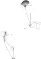
- FIG. 1 illustrates a captive wing traction system 1, mounted on a vessel 2 which is, in this example, a maritime freight vessel (on the Figure 1 , only the front of the ship was shown).
- the traction system 1 is mounted at the bow of the vessel 2 and is operated as a supplementary means of propulsion of the vessel allowing fuel savings.
- the traction system 1 is sized according to the tonnage of the vessel to be towed and is intended to be deployed and folded automatically.
- this traction system 1 may be used for any other application where such an automatically deployable and foldable traction system is desired, for example as the primary means of propulsion of a ship, for the propulsion of any other vehicle, for the production of electricity, etc.
- the traction system 1 comprises a base platform 3 which is here fixed on the deck of the ship 2 and on which is mounted a mooring mast 4 provided for the automatic deployment and retraction operations of the system.
- the traction system 1 further comprises a traction wing 5 which is adapted to generate a traction force under the effect of the wind.
- the traction wing 5 is a paraglider-type sail. Any other flying equipment adapted to generate a traction force under the effect of the wind may alternatively be used, such as kites, gliding equipment, kite-type sails, etc.
- the traction wing 5 comprises, in a conventional manner, a leading edge 16 intended to be exposed to the incident wind and an opposite edge, called the trailing edge 17.
- the traction wing 5 is connected by a set of suspension lines 6 to a flight control device 7 which is adapted to act on the suspension lines 6 to control the flight of the traction wing 5.
- the traction system 1 further comprises a traction line 8 connecting the flight control device 7 to the base platform 3.
- the traction force generated by the traction wing 5 is transmitted by the traction line 8 to the ship 2 for its propulsion, and the traction line is dimensioned accordingly.
- the traction line can be, for example, a textile cable whose diameter can reach several centimeters.
- the flying trajectory control device 7 makes it possible to control the flight of the traction wing 5 in order to orient and position the traction wing and possibly to cause the traction wing 5 to describe flight figures making it possible to increase the traction force on the ship.
- the control of the trajectory of the traction wing 5 is here obtained by controlling the length of certain movable suspension lines, in a conventional manner in the field of flying wings.
- the set of suspension lines 6 in fact comprises fixed suspension lines (i.e. which have a fixed length between their attachment to the traction wing 5 and their attachment to the flying trajectory control device 7), and movable suspension lines whose length is variable.
- the flight control device 7 is thus adapted to pull on certain movable suspension lines and/or to release other movable suspension lines, so that the aerodynamic profile of the traction wing 5 is modified in order to control its lift, its trajectory, etc.
- the modification of the profile of a traction wing for the control of its trajectory is carried out in a conventional manner and will not be described in more detail here.
- the traction wing 5 further comprises a guide line 9 and several folding lines 10A, 10B, 10C which are all integral with the leading edge 16, by at least one of their ends.
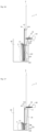
- FIG. 2 is a profile view of the traction system 1 in the traction phase of the ship, as in the Figure 1 .
- FIG 2 further schematically illustrates the constituent elements of the traction system 1.
- the traction line 8 is connected to the base platform 3 by means of a winch 11 controlled by a motor, for example electric or hydraulic, adapted to unwind the traction line 8 to allow the traction wing 5 to gain altitude, or on the contrary to wind this traction line 8 to bring the traction wing 5 back to the base platform 3.
- a winch 11 controlled by a motor, for example electric or hydraulic, adapted to unwind the traction line 8 to allow the traction wing 5 to gain altitude, or on the contrary to wind this traction line 8 to bring the traction wing 5 back to the base platform 3.
- FIGS. 1 and 2 illustrate the traction system 1 in a traction configuration, with the traction wing 5 deployed and in flight, and the system participating in the propulsion of the vessel.
- the traction wing 5 has a furling line 13 which is divided into several lines (shown in dotted lines on the Figure 2 ) whose ends are connected to the trailing edge 17 of the wing 5.
- This furling line 13 can be grasped at the trailing edge 16 of the traction wing 5, and traction on this furling line 13 causes the wing 5 to be furled by compression in order to stow it.
- the traction system 1 comprises trolleys 12A, 12B, 12C, 12D, 12E, which are five in number in the present example. These trolleys are fixed in a sliding manner on the lashing mast 4 and each comprise a motorization so that the position of each trolley along the lashing mast 4 can be controlled. These trolleys are provided to grip and guide the folding lines 10A, 10B, 10C and the furling line 13 during the deployment or retraction phases described later.
- the traction system 1 comprises as many trolleys as necessary to grip the folding or furling lines, the number of which may vary from the example described.
- the traction system 1 further comprises a control module 64 which controls the movement of the carriages 12A, 12B, 12C, 12D, 12E as well as the devices of each of the carriages for gripping the folding or furling lines.
- This control module 64 is produced in a conventional manner by electronic and computer equipment adapted to this application, and programmed to implement in particular the method of deploying and retracting the traction wing 5.
- the fold lines 10A, 10B, 10C are arranged in pairs as shown in Figure 3 .
- the leading edge 16 of the traction wing 5 is, in the present description, divided into a median zone 15 and into two lateral edges 19 extending on either side of this median zone 15, between the median zone 15 and each of the lateral ends 18 of the leading edge 16.
- FIG. 3 also illustrates the path of the guide line 9 between the central portion 15 and the flight control device 7.
- the traction system 1 comprises a lashing line 20 which is wound onto a lashing winch 21 mounted on the base platform 3.
- the lashing line 20 starts from the winch 21 and is then guided into the lashing trolley 12B by one or more pulleys (or by low-friction elements, or any other element allowing the lashing line 20 to be slidably routed into the lashing trolley 12B).
- the lashing line 20 then passes into a shuttle 14 which is slidable along the guide line 9.
- the traction wing 5 can be folded according to the method described below.
- the winches 11 and 21 are first commanded to bring back the traction line 8 and the lashing line 20 so that the flying trajectory control device 7 comes to rest on the base platform 3, while the shuttle 14 rises along the guide line 9 as the traction wing 5 descends.
- the lashing line 20 passes into the lashing trolley 12B and holds the leading edge 16 by pulling against the lashing trolley 12B.
- the pulling wing 5 is then locked in this lashed position (as described later), the tension on the lashing line 20 is no longer necessary, and the gripping of the lines can take place.
- Line captures are made using hooks on the carriages, as well as a capture device, as explained later.
- the folding trolleys 12C, 12D, 12E then begin a downward movement along the lashing mast 4 by sliding their hooks along the lines that have been hooked.
- FIG. 5 is a perspective view illustrating this operation of lowering the folding trolleys.
- Each of the folding trolleys 12C, 12D, 12E thus drives each of the folding lines progressively towards a configuration where the lines are stretched vertically from the middle zone 15 (which is secured to the lashing trolley 12B which remains fixed), along the lashing mast 4. This operation makes it possible to bring the lateral portions 19 vertically along the lashing mast 4.
- THE figures 6 (side view) and 7 (perspective view) illustrate the traction wing 5 after this folding operation, that is to say when the folding carriages 12C, 12D, 12E are each in their respective lower position.
- the traction wing 5 is then folded along the lashing mast 4, that is to say that the two lateral portions 19 of the leading edge 16 extend vertically along the lashing mast 4, while the middle zone 15 is kept lashed against the lashing trolley 12B.
- the wing 5 can then be furled.
- the furling carriage 12A (which has gripped the furling line 13) is then commanded to slide upwards along the lashing mast 4, and thus exerts traction on the furling line 13, which causes the furling of the traction wing 5.
- the furling is done by compression, by bringing the trailing edge 17 closer to the leading edge 16.
- the securing of the traction wing 5 relative to the securing trolley 12B is achieved by the cooperation of the securing line 20, the securing trolley 12B, the shuttle 14, and a line gripping device 22.
- FIG 8 is a detail view of the Figure 3 , illustrating the traction wing 5 seen from the front and showing the middle zone 15, and the connection of the fold lines 10A, 10B, 10C and from the furling line 13 to the middle zone 15 of the leading edge 16, via the gripping device 22.
- the gripping device 22 is connected to the leading edge 16 of the traction wing 5, at the level of the median zone 15, by a pylon 23 (visible in particular on the side view of the figure 9 ).
- the pylon 23 is thus named by analogy with the pylon of an aircraft, that is to say the reactor mast, in aeronautical terms.
- the pylon 23 is preferably made of a rib of light and resistant material such as a carbon fiber composite material.
- the pylon 23 is fixed on the gripping device 22 and on a reinforcement sewn on the leading edge 16 of the traction wing 5.
- the gripping device 22 may, alternatively, be connected by any other means, flexible or rigid, to the leading edge 16, such as textile ties or any other element making it possible to ensure that traction on the gripping device 22 causes traction on the leading edge 16.
- the gripping device 22 comprises a body 24 and two hooking arms 25, pivotally mounted on this body 24, each around an axis 26.
- Each of the hooking arms 25 comprises a first hooking rod 27A, a second hooking rod 27B of greater length, and a third hooking rod 27C of even greater length (the hooking rods 27A, 27B, 27C are seen in section on the figure 8 ).
- This arrangement in which the juxtaposed hanging rods have an increasing or decreasing length is here called "staircase".
- the hooking rods 27A, 27B, 27C are constituted by tubes force-fitted into bores provided for this purpose in the hooking arm 25.
- the attachment arms are movable relative to the body 24, between a flight position (that of the figure 8 ) and a hooking position in which the hooking rods 27A, 27B, 27C are arranged substantially vertically (when the traction wing 5 is in its normal lashing position).
- Each hooking arm 25 further comprises a lever 28, that is to say a portion extending beyond the axis 26 and making it possible to act on the hooking arm 25 to fold it.
- Each fold line 10A, 10B, 10D, 10C which joins the middle zone 15 is connected to a hooking rod 27A, 27B, 27C so as to be projecting in the extension of this hooking rod.
- the end of the hooking rod is extended by the fold line.
- the folding line is advantageously inserted into the tube, crosses the entire tube, up to a fixing zone 29 of the hanging arm 25.
- the pivot connection between the hooking arms 25 and the body 24 allows the hooking arm 25 to naturally assume the spread position illustrated in figure 8 during the flight of the traction wing 5, the attachment arms 25 thus follow the opening dictated by the folding lines 10A, 10B, 10C which extend towards their other end connected further on the leading edge 16.
- the gripping device 22 may, in addition, comprise an elastic element (spring or other) urging the attachment arms 25 towards their position of separation from the figure 8 .
- This spacing position of the hooking arms 25 has the function of further securing the automatic hooking of the lines, by limiting the risks of tangling of the hooking arms 25 and the hooking rods 27A, 27B, 27C with the other lines such as the guide line 9 and the lashing line 20.
- the Shuttle 14 is also shown in section on the figure 8
- the shuttle 14 has two sliding orifices 32, and is here oblong in shape with two lateral flats 33.
- the oblong shape of the shuttle 14 allows guidance and angular orientation around a horizontal axis of the gripping device 22.
- the guide line 9 here consists of a pair of lines stretched between the body 24 and the flight control device 7.
- the pair of guide lines 9 forms a loop around a stop 34 of the body 24.
- the guide line 9 is thus attached to the middle zone 15 by means of the gripping device 22.
- the lashing line 20 passes through the shuttle 14 and is connected to the body 24.
- the shuttle 14 comprises a guide means crossed by the lashing line 20 and allowing the free sliding of the lashing line 20.
- This guide means is carried out by any type of guiding means, such as pulleys or low-friction elements.
- the lashing line 20 thus extends from the lashing trolley 12B, crosses the shuttle 14 in a sliding manner, being guided towards the body 24.
- FIG. 9 illustrates the gripping device 22 seen from the side and arranged opposite a nesting interface 35 which is fixed on the lashing trolley 12B (the rest of the lashing trolley 12B has not been shown).
- the nesting interface 35 comprises elements allowing the gripping device 22 to be secured in a predefined position.
- these elements comprise a recess 39 which is complementary to a recess 40 of the body 24.
- the shuttle 14 is also part of these positioning elements, since it is designed to engage in an imprint 41 of the nesting interface 35.
- the recess 40 also has a significant advantage in terms of force absorption, since the cooperation of the recesses 39 and 40 makes it possible to absorb all of the vertical forces which will be exerted on the gripping device 22 during the folding operations, these forces possibly being greater than 15 kN.
- the imprint 41 comprises internal walls for receiving and positioning the shuttle 14.
- FIG. 9 also illustrates the arrangement of the furling line 13.
- the gripping device 22 comprises a furling rod 42 projecting vertically from above the body 24.
- the furling line 13 projects in the extension of the furling rod 24.
- the furling rod 42 is produced by a tube fitted into the body 24, the furling line passing through this tube and its end being fixed to the body 24.
- the furling line 13 Between its attachment to the furling rod 42 and its path towards the trailing edge 17, the furling line 13 forms a loop 55 and passes through a ring 43 which is integral with the tube 42.
- the ring 43 is for example a low friction ring, or can be achieved by a tube or a pulley. A pull on the loop 55 thus causes a pull on the furling line 13 and therefore the furling of the traction wing 5.
- the traction on the lashing line 20, during the lashing phase of the traction wing causes the shuttle 14 to rise and ends with the shuttle 14 entering the housing 36.
- the shuttle 14 is then immobilized in the housing 36, thanks to the dimensional adjustment allowing the flats 33, 38 to bear plane on plane against internal surfaces of the housing 36.
- the shuttle 14 is thus movable between a sliding configuration in which it slides along the guide line 9, and a docking configuration in which the shuttle 14 is arranged in its housing 36.
- the entry of the shuttle 14 into the housing 36 further activates the levers 28, which causes the hooking arms 25 to close, i.e. to move them into a vertical position, and to be held in this position by the presence of the shuttle 14.
- the traction on the lashing line 20 causes the gripping device 22 to move closer to the nesting interface 35, until these two elements are coupled.
- FIG. 10 illustrates the gripping device 22 thus secured to the lashing trolley 12B.
- This figure also illustrates the other trolleys 12A, 12C, 12D, 12E.
- Each of the trolleys can slide along the lashing mast 4, in a controlled manner, using actuators 66A, 66B, 66C, 66D, 66E.
- the tie-down trolley 12B includes an upper immobilizing hook 48 and a pair of lower immobilizing hooks 49, which are movable between a retracted position, in which they are clear of the gripping device 22, and an immobilizing position (that shown in FIG. Figure 10 ), in which they respectively block the body 24 and the hooking arms 25 against the nesting interface 35.
- Each of the folding carriages 12C, 12D, 12E comprises a pair of gripping hooks 46A, 46B, 46C, each of these pairs of gripping hooks being intended to hook the pair of folding lines 10A, 10B, 10C which corresponds to it.
- These hooks 12C, 12D, 12E are in the retracted position on the Figure 10 .
- the furling trolley 12A has a gripping hook 47 intended to actuate the furling line 13 by the loop 55.
- the gripping hook 47 is also retracted on the Figure 10 .
- Hooks 46A, 46B, 46C, 47, 48 are pivoting hooks in yokes secured to the corresponding carriage.
- FIG. 10 illustrates the sliding actuators 66A, 66B, 66C, 66D, 66E which equip the trolleys 12A, 12B, 12C, 12D, 12E respectively.
- Each trolley thus comprises a sliding actuator 66A, 66B, 66C, 66D, 66E which is controlled by the control module 64 and which makes it possible to control the sliding, or the holding in fixed position, of each trolley along the lashing mast 4.
- these sliding actuators are each constituted by an electric motor coupled to a pinion meshing on a rack fixed along the lashing mast.
- these sliding actuators can be constituted by any means allowing this function, for example linear motors, remote rotary motors with chain or belt transmission, etc.
- the immobilizing hooks 48, 49 of the lashing trolley 12B are activated towards their immobilizing position to fix the gripping device 22 on the nesting interface 35, as illustrated in FIG. Figure 10 . From this stage, the traction of the lashing line 20 is no longer necessary to maintain the lashing.
- the upper immobilizing hook 48 grips the upper part of the body 24 while the lower immobilizing hooks 49 grip the hooking arms 25, at the level of the fixing zone 29, that is to say above the hooking rods 27A, 27B, 27C.
- the activation of the hooks 48, 49 can be done by any means, such as for example a pivoting controlled by an electric motor, or remotely controlled magnetic actuation means.
- the actuation of the hooks 48, 49 is done by the movement of the furling carriage 12A.
- Figure 11 represents the carriages in transparency to make the mechanism visible.
- the hooks 48, 49 are each rotatably mounted on the carriage and are actuable either by a shaft or by pinions.
- a control shaft 50 makes it possible to actuate in rotation all three hooks 48, 49, thanks to the arrangement of the pinions.
- the same type of mechanism allows, when the furling carriage 12A continues to move away from the lashing carriage 12B, to also drive the furling hook 47 towards its gripping position, thanks to a control shaft cooperating with a helical cam path.
- the gripping hooks 46A, 46B, 46C of the folding carriages 12C, 12D, 12E can also be controlled by any means allowing them to be closed on the hooking rods 27A, 27B, 27C.
- the passage of the gripping hooks 46A, 46B, 46C to their gripping position is preferably controlled by the distance of the corresponding folding carriage from the previous carriage, thanks to the same type of control as before, with control shaft, lug, and helical cam path.
- the furling trolley 12A is first slightly moved away from the lashing trolley 12B, which causes the immobilizing hooks 48, 49 to close and the gripping device 22 to be immobilized.
- the furling trolley 12A then remains in this position, the hook 47 being in the retracted position.
- the folding trolleys 12C, 12D, 12E then each begin a downward movement along the lashing mast 4, moving away from each other so that the pairs of hooks 46A, 46B, 46C close on the hooking rods 27A, 27B, 27C, as illustrated in Figure 10 .
- Each hook 46A of the first folding carriage 12C closes on the three hooking rods 27A, 27B, 27C, that is to say just above the end of the first hooking rods 27A.
- Each hook 46B of the second folding carriage 12D closes on two hooking rods 27B, 27C, that is to say just above the end of the second hooking rods 27B.
- Each hook 46C of the third folding carriage 12E closes only on a third hooking rod 27C, just above the end of the third hooking rods 27C.
- Each of the pairs of folding hooks 46A, 46B, 46C is therefore in this position of the Figure 10 , just above the exit of the fold lines 10A, 10B, 10C which correspond to it.
- the traction wing 5 can then be furled.
- the furling of the traction wing 5 is carried out by a mutual separation of the lashing trolleys 12B and the furling trolley 12A, which first causes the furling hook 47 to close on the furling rod 42 (see Figure 10 ).
- the pursuit of the raising the furling trolley 12A then causes traction on loop 55 (loop 55 is visible at Figure 9 , and has not been shown in the other figures).
- Figure 4 illustrates the stowed position of the traction wing 5 following this operation, the leading edge 16 of the traction wing 5 being stowed to the stowage trolley 12B (this stowage is done, in the present example, by means of the gripping device 22).
- the folding carriages 12C, 12D, 12E then grasp the folding lines 10A, 10B, 10C using their respective hooks 46A, 46B, 46C.
- control module 64 controls the sliding of the folding carriages 12C, 12D, 12E along the lashing mast 4, to reach the folding position of the Figure 6 .
- the control module 64 includes for this purpose, in its programming, a first operating mode called “folding mode”, in which the folding trolleys 12C, 12D, 12E are moved away from the lashing trolley 12B.
- folding mode a first operating mode in which the folding trolleys 12C, 12D, 12E are moved away from the lashing trolley 12B.
- the lashing trolley 12B remains fixed on the lashing mast 4 while the folding trolleys 12C, 12D, 12E each descend along the lashing mast 4, to the folding position illustrated in Figure 6 .
- the independent control of the trolleys also makes it possible to carry out additional functions, such as folding the traction wing 5 into a windsock (by closing its trailing edges) by exerting traction on closing lines (not shown) which are connected to the trailing edge 17, this traction being able to be optimized and managed by the movements of the trolleys.
- the traction wing will then be simultaneously furled and stored in a storage container 65, with reference to the figures 12 to 17 .
- THE figures 12 to 17 illustrate an additional detail of the traction system 1: the lashing mast 4 extends below the base platform 3, and a storage container 65 for the traction wing 5 is arranged opposite the lashing mast 4 at this extension.
- the furling trolley 12A grasps the furling line 13 at the level of the furling loop 55, thanks to its hook 47.
- the furling line 13 can be grasped at any other time after the lashing has been carried out, in particular at the position of the Figure 4 or of the Figure 6 .
- the lashing carriage 12B, as well as the folding carriages 12C, 12D, 12E will all four be simultaneously controlled in downward translation. In other words, these four carriages 12B, 12C, 12D, 12E will each slide downward along the lashing mast 4, while maintaining their respective mutual spacings.
- control module 64 includes in its programming a second operating mode called “furling mode”, in which the lashing trolley 12B and the furling trolley 12A are spaced apart from each other.
- furling mode a second operating mode
- the furling trolley 12A remains fixed on the lashing mast 4 while the lashing trolley 12B slides downwards.
- the folding trolleys 12C, 12D, 12E also descend along the lashing mast 4, together with the lashing trolley 12B.
- control module 64 is therefore adapted to control the descent of the lashing trolley 12B as well as the descent of at least one folding trolley so that the spacing between these trolleys remains constant.
- the lashing winch 21 is further controlled by the control module 64 so as to gradually wind the lashing line 20.
- the lashing line 20 thus always has a slight tension guaranteeing that no unwanted loops will form on the path of the lashing line 20. Slack in the lashing arrival line 20 would in fact risk causing untimely blockages of this lashing line 20, for example around one of the mobile elements of the system.
- the control module 64 keeps the furling carriage 12A fixed on the lashing mast 4.
- the separation of the furling carriage 12A and the lashing carriage 12B causes a pull on the furling loop 55.
- the furling carriage 12A having grasped the furling loop 55 in a sliding manner, by the hook 47, this movement causes a direct pull on the furling line 13, and therefore the furling of the traction wing 5.
- the figure 13 illustrates the furling of the traction wing 5 by bringing the trailing edge 17 closer to the leading edge 16 (shown schematically by the dotted lines on the figure 13 ).
- FIG 14 illustrates a next step in the descent of the traction wing 5 while the control module 64 is in furling mode.
- the traction wing 5 continues its translation while maintaining its folding position (the relative position of the lashing trolleys 12B and folding trolleys 12C, 12D, 12E not having been modified) while the furling trolley 12A is kept fixed, and the furling of the traction wing 5 continues.
- the control module 64 then switches to another operating mode called “storage mode”, whereby the traction wing will be stored in the container 65.
- the furling trolley 12A and the lashing trolley 12B descend jointly along the lashing mast 4, the control module 64 maintaining their mutual spacing, while the folding trolleys 12C, 12D, 12E are brought closer to each other.
- the lashing trolley 12B therefore approaches at least one folding trolley 12A, 12B, 12C.
- the lashing trolley 12B and the first two folding trolleys 12C, 12D approach together the third folding trolley 12E (which is held fixed in its lower stop position), then the second folding trolley joins 12D joins the third folding trolley 12E (this is the position illustrated in figure 16 ).
- the first folding carriage 12C then joins the second folding carriage 12D, until a position where the four carriages 12B, 12C, 12D, 12E come into abutment close to each other (the configuration illustrated in Figure 17 ).
- all the folding trolleys 12C, 12D, 12E can be simultaneously brought closer to the lashing trolley 12B when the latter slides downwards.
- the furling trolley 12A and the lashing trolley 12B slide downwards while maintaining their mutual distance constant, and at least one of the folding trolleys 12C, 12D, 12E slides downwards at a speed lower than the sliding speed of the lashing trolley 12B.
- FIG. 17 illustrates this final position in which the traction wing 5 is now stored in the storage container 65.
- the lashing trolley 12B and the folding trolleys 12C, 12D, 12E are close to each other (or even abutting against each other), and the spacing between the furling trolley 12A and the lashing trolley 12B has been kept identical (the furling trolley 12A has slid along the lashing mast together with the lashing trolley 12B).
- the lashing line 20 is kept under slight tension as explained previously thanks to the control of the lashing winch 21.
- maintaining the mutual spacing between the furling trolley 12A and the lashing trolley 12B makes it possible to keep the sail furled during its storage.
- the sail can thus be stored in the storage container 65 in this position of the Figure 17 if it is desired to keep the sail furled even during storage.
- the folding, furling and storage operations of the traction wing 5 are thus interlinked by the set of carriages 12A, 12B, 12C, 12D, 12E.
- Other functions can also be performed by this set of carriages, such as closing the trailing edge of the traction wing, by pulling on closing lines.
- sliding actuators 66A, 66B, 66C, 66D, 66E can be individual actuators for each corresponding carriage, or be shared by a single common actuator associated with suitable transmission means for each of the carriages.
- the operating modes of the control module can optionally be implemented sequentially in a different order, or simultaneously.
- the traction wing 5 is simultaneously furled and stored in the storage container 65.
Landscapes
- Engineering & Computer Science (AREA)
- Life Sciences & Earth Sciences (AREA)
- Sustainable Development (AREA)
- Sustainable Energy (AREA)
- Chemical & Material Sciences (AREA)
- Combustion & Propulsion (AREA)
- Mechanical Engineering (AREA)
- Ocean & Marine Engineering (AREA)
- Handcart (AREA)
- Folding Of Thin Sheet-Like Materials, Special Discharging Devices, And Others (AREA)
- Ship Loading And Unloading (AREA)
- Catching Or Destruction (AREA)
Claims (19)
- Schleppsystem mit angebundenem Schirm, das Folgendes aufweist:- einen Schleppschirm (5), der dazu geeignet ist, unter dem Einfluss von Wind eine Zugkraft zu erzeugen, wobei der Schleppschirm (5) eine Anströmkante (16) und eine Abströmkante (17) aufweist;- eine Basisplattform (3), mit der der Schleppschirm über eine Schleppleine (8) verbunden ist, wobei der Schleppschirm (5) so beschaffen ist, dass er in Bezug auf diese Basisplattform (3) entfaltet und zusammengefaltet werden kann;- einen Befestigungsmast (4) für den Schleppschirm (5), der auf der Basisplattform (3) angeordnet ist;- mehrere Faltleinen (10A, 10B, 10C), von denen jede ein Ende hat, das an der Anströmkante (16) des Schleppschirms (5) befestigt ist, und die entlang dieser Anströmkante (16) voneinander beabstandet sind;- eine Zurrleine (13), die mit der Abströmkante (17) des Schleppschirms (5) verbunden ist;wobei dieses Schleppsystem mit angebundenem Schirm dadurch gekennzeichnet ist, dass es Folgendes aufweist:- einen Befestigungsschlitten (12B), der dazu geeignet ist, entlang des Befestigungsmastes (4) zu gleiten, und der durch einen Schiebeantrieb (66B) gesteuert wird, wobei dieser Befestigungsschlitten (12B) eine Einsteckschnittstelle (35) aufweist, die dazu geeignet ist, die Anströmkante (16) des Schleppschirms (5) festzuhalten;- einen Faltschlitten (12C, 12D, 12E), der dazu geeignet ist, entlang des Befestigungsmastes (4) zu gleiten, und der durch einen Schiebeantrieb (66C, 66D, 66E) gesteuert wird, wobei dieser Faltschlitten (12C, 12D, 12E) Greifmittel (46A, 46B, 46C) aufweist, die dazu geeignet sind, mindestens eine Faltleine (10A, 10B, 10C) zu greifen;- einen Zurrschlitten (12A), der dazu geeignet ist, entlang des Befestigungsmastes (4) zu gleiten, und der durch einen Schiebeantrieb (66A) gesteuert wird, wobei dieser Zurrschlitten (12A) Greifmittel (47) aufweist, die dazu geeignet sind, die Zurrleine (13) zu greifen;- ein Steuermodul (64) für die Schiebeantriebe (66A, 66B, 66C, 66D, 66E), wobei dieses Steuermodul (64) mindestens die folgenden zwei Betriebsarten aufweist:einen Faltmodus, in dem der Befestigungsschlitten (12B) und der Faltschlitten (12C, 12D, 12E) voneinander entfernt sind;einen Zurrmodus, in dem der Zurrschlitten (12A) und der Befestigungsschlitten (12B) voneinander entfernt sind.
- Schleppsystem mit angebundenem Schirm nach Anspruch 1, dadurch gekennzeichnet, dass im Faltmodus der Befestigungsschlitten (12B) fest an dem Befestigungsmast (4) gehalten wird und der Faltschlitten (12C, 12D, 12E) nach unten gleitet.
- Schleppsystem mit angebundenem Schirm nach einem der vorhergehenden Ansprüche, dadurch gekennzeichnet, dass im Zurrmodus der Zurrschlitten (12A) fest an dem Befestigungsmast (4) gehalten wird und der Befestigungsschlitten (12B) nach unten gleitet.
- Schleppsystem mit angebundenem Schirm nach einem der Ansprüche 1 oder 2, dadurch gekennzeichnet, dass im Zurrmodus der Zurrschlitten (12A) nach oben gleitet und der Befestigungsschlitten (12B) fest an dem Befestigungsmast (4) gehalten wird.
- Schleppsystem mit angebundenem Schirm nach Anspruch 4, dadurch gekennzeichnet, dass im Zurrmodus der Faltschlitten (12C, 12D, 12E) ebenfalls nach unten gleitet, wobei der Abstand zwischen dem Befestigungsschlitten (12B) und dem Faltschlitten (12C, 12D, 12E) konstant gehalten wird.
- Schleppsystem mit angebundenem Schirm nach einem der vorhergehenden Ansprüche, dadurch gekennzeichnet, dass das Steuermodul (64) zusätzlich den folgenden Betriebsmodus aufweist: einen Lösemodus, in dem der Zurrschlitten (12A) und der Befestigungsschlitten (12B) aufeinander zu bewegt werden.
- Schleppsystem mit angebundenem Schirm nach Anspruch 6, dadurch gekennzeichnet, dass im Lösemodus der Zurrschlitten (12A) fest an dem Befestigungsmast (4) gehalten wird und der Befestigungsschlitten (12B) nach oben gleitet.
- Schleppsystem mit angebundenem Schirm nach einem der vorhergehenden Ansprüche, dadurch gekennzeichnet, dass das Steuermodul (64) zusätzlich den folgenden Betriebsmodus aufweist: einen Entfaltmodus, in dem der Befestigungsschlitten (12B) und der Faltschlitten(12C, 12D, 12E) aufeinander zu bewegt werden.
- Schleppsystem mit angebundenem Schirm nach Anspruch 8, dadurch gekennzeichnet, dass im Entfaltmodus der Befestigungsschlitten (12B) fest an dem Befestigungsmast (4) gehalten wird und der Faltschlitten (12C, 12D, 12E) nach oben gleitet.
- Schleppsystem mit angebundenem Schirm nach einem der vorhergehenden Ansprüche, dadurch gekennzeichnet, dass das Steuermodul (64) zusätzlich den folgenden Betriebsmodus aufweist: einen Lagermodus, in dem der Abstand zwischen dem Zurrschlitten (12A) und dem Befestigungsschlitten (12B) konstant gehalten wird, während der Befestigungsschlitten (12B) und der Faltschlitten (12C, 12D, 12E) aufeinander zu bewegt werden.
- Schleppsystem mit angebundenem Schirm nach Anspruch 10, dadurch gekennzeichnet, dass im Lagermodus der Zurrschlitten (12A) und der Befestigungsschlitten (12B) nach unten gleiten, wobei ihr gegenseitiger Abstand konstant gehalten wird, und der Faltschlitten (12C, 12D, 12E) mit einer Geschwindigkeit nach unten gleitet, die geringer ist als die Gleitgeschwindigkeit des Befestigungsschlittens (12B).
- Schleppsystem mit angebundenem Schirm nach Anspruch 10, dadurch gekennzeichnet, dass im Lagermodus der Befestigungsschlitten (12C, 12D, 12E) festgehalten wird.
- Schleppsystem mit angebundenem Schirm nach einem der Ansprüche 10 bis 12, dadurch gekennzeichnet, dass das Steuermodul (64) zusätzlich den folgenden Betriebsmodus aufweist: einen Auslagermodus, in dem der Abstand zwischen dem Zurrschlitten (12A) und dem Befestigungsschlitten (12B) konstant gehalten wird, während der Befestigungsschlitten (12B) und der Faltschlitten (12C, 12D, 12E) voneinander weg bewegt werden.
- Schleppsystem mit angebundenem Schirm nach Anspruch 13, dadurch gekennzeichnet, dass im Auslagermodus der Zurrschlitten (12A) und der Befestigungsschlitten (12B) nach oben gleiten, wobei ihr gegenseitiger Abstand konstant gehalten wird, und der Faltschlitten (12C, 12D, 12E) mit einer Geschwindigkeit nach oben gleitet, die geringer ist als die Gleitgeschwindigkeit des Befestigungsschlittens (12B).
- Schleppsystem mit angebundenem Schirm nach einem der vorhergehenden Ansprüche, dadurch gekennzeichnet, dass es eine Leinengreifvorrichtung (22) aufweist, die mit der Anströmkante (16) des Schleppschirms (5) verbunden ist und die dazu ausgelegt ist, mit der Einsteckschnittstelle (35) des Befestigungsschlittens (12B) zusammenzupassen, wobei der Zurrschlitten (12A) dazu ausgelegt ist, die Zurrleine (13) auf der Leinengreifvorrichtung (22) zu ergreifen, und der Faltschlitten (12C, 12D, 12E) dazu ausgelegt ist, mindestens eine Faltleine (10A, 10B, 10C) auf der Leinengreifvorrichtung (22) zu ergreifen.
- Schleppsystem mit angebundenem Schirm nach einem der vorhergehenden Ansprüche, dadurch gekennzeichnet, dass es eine Leine (20) zum Befestigen des Schleppschirms (5) an der Einsteckschnittstelle (35) des Befestigungsschlittens (12B) aufweist, wobei die Länge dieser Befestigungsleine (20) durch das Steuermodul (64) so gesteuert wird, dass die Befestigungsleine (20) während des Zurrmodus und des Faltmodus unter Spannung gehalten wird.
- Schleppsystem mit angebundenem Schirm nach Anspruch 16, das, wenn es von den Ansprüchen 10 bis 14 abhängt, dadurch gekennzeichnet ist, dass die Länge der Befestigungsleine (20) durch das Steuermodul (64) so gesteuert wird, dass die Befestigungsleine (20) auch während des Lagermodus unter Spannung gehalten wird.
- Verfahren zum Zusammenfalten des Schleppschirms eines Schleppsystems nach einem der Ansprüche 1 bis 17, dadurch gekennzeichnet, dass es die folgenden Schritte aufweist:- Befestigen der Anströmkante (16) des Schleppschirms (5) am Befestigungsschlitten (12B);- Ergreifen mindestens einer Faltleine (10A,10B,10C) mit dem Faltschlitten (12C,12D,12E);- Schieben des Faltschlittens (12C,12D,12E) nach unten, während der Befestigungsschlitten (12B) fest an dem Befestigungsmast (4) gehalten wird;- Ergreifen der Zurrleine (13) durch den Zurrschlitten (12A);- Schieben des Befestigungsschlittens (12B) nach unten, während der Zurrschlitten (12A) fest an dem Befestigungsmast (4) gehalten wird.
- Verfahren zum Entfalten des Schleppschirms eines Schleppsystems nach einem der Ansprüche 1 bis 17, dadurch gekennzeichnet, dass es die folgenden Schritte aufweist:- Schieben des Befestigungsschlittens (12B) nach oben, während der Zurrschlitten (12A) fest an dem Befestigungsmast (4) gehalten wird;- Schieben des Faltschlittens (12C,12D,12E) nach oben, während der Befestigungsschlitten (12B) fest an dem Befestigungsmast (4) gehalten wird.
Applications Claiming Priority (2)
| Application Number | Priority Date | Filing Date | Title |
|---|---|---|---|
| FR2102791A FR3120847B1 (fr) | 2021-03-19 | 2021-03-19 | Système de traction à aile captive et procédé de déplacement des charriots |
| PCT/EP2022/056811 WO2022194927A1 (fr) | 2021-03-19 | 2022-03-16 | Systeme de traction a aile captive et procede de deplacement des charriots |
Publications (2)
| Publication Number | Publication Date |
|---|---|
| EP4308448A1 EP4308448A1 (de) | 2024-01-24 |
| EP4308448B1 true EP4308448B1 (de) | 2025-06-11 |
Family
ID=75539639
Family Applications (1)
| Application Number | Title | Priority Date | Filing Date |
|---|---|---|---|
| EP22715081.0A Active EP4308448B1 (de) | 2021-03-19 | 2022-03-16 | Schleppsystem mit gefangenem segel und verfahren zur bewegung der wagen |
Country Status (9)
| Country | Link |
|---|---|
| US (1) | US20240149997A1 (de) |
| EP (1) | EP4308448B1 (de) |
| JP (1) | JP2024510153A (de) |
| KR (1) | KR20230157410A (de) |
| CN (1) | CN116940506A (de) |
| CA (1) | CA3211485A1 (de) |
| DK (1) | DK4308448T3 (de) |
| FR (1) | FR3120847B1 (de) |
| WO (1) | WO2022194927A1 (de) |
Families Citing this family (1)
| Publication number | Priority date | Publication date | Assignee | Title |
|---|---|---|---|---|
| FR3120845B1 (fr) * | 2021-03-19 | 2023-03-10 | Airseas | Système de traction à aile captive avec pliage en manche à air |
Family Cites Families (8)
| Publication number | Priority date | Publication date | Assignee | Title |
|---|---|---|---|---|
| FR2822802B1 (fr) * | 2001-03-29 | 2004-05-14 | Maurice Grenier | Embarcation nautique tractee par une voilure cerf-volant |
| DE102004018814A1 (de) * | 2004-04-19 | 2005-11-03 | Skysails Gmbh | Setzsystem für ein ausfliegendes drachenartiges Windangriffselement bei einem Wasserfahrzeug mit Windantrieb |
| PL2213568T3 (pl) * | 2006-08-15 | 2013-09-30 | Skysails Gmbh & Co Kg | Urządzenie do startu i zwijania przeznaczone do aerodynamicznego elementu profilowanego |
| NZ583494A (en) * | 2007-08-24 | 2012-12-21 | Skysails Gmbh & Co Kg | Propulsive parasail for a watercraft and method for control |
| DE102009034999A1 (de) * | 2009-07-27 | 2011-02-03 | Robert Dietrich | Steuerungshilfsvorrichtung für frei ausfliegende Windangriffselemente mit einer Tragflächengröße von mehr als 20 m2 |
| CN104890845B (zh) * | 2015-06-23 | 2017-04-05 | 江苏科技大学 | 横向可折叠自动收放翼型帆 |
| DE202016006694U1 (de) * | 2016-10-24 | 2016-12-21 | Steffen Born | Zugdrachen mit veränderbarer Segelflächentiefe während des Fluges |
| FR3082184B1 (fr) * | 2018-06-11 | 2020-07-03 | Airseas | Systeme comprenant une voile captive et un poste fixe avec des moyens de pliage de la voile au poste fixe |
-
2021
- 2021-03-19 FR FR2102791A patent/FR3120847B1/fr active Active
-
2022
- 2022-03-16 KR KR1020237034716A patent/KR20230157410A/ko active Pending
- 2022-03-16 EP EP22715081.0A patent/EP4308448B1/de active Active
- 2022-03-16 WO PCT/EP2022/056811 patent/WO2022194927A1/fr not_active Ceased
- 2022-03-16 JP JP2023553992A patent/JP2024510153A/ja active Pending
- 2022-03-16 CA CA3211485A patent/CA3211485A1/fr active Pending
- 2022-03-16 US US18/549,910 patent/US20240149997A1/en active Pending
- 2022-03-16 CN CN202280019425.XA patent/CN116940506A/zh active Pending
- 2022-03-16 DK DK22715081.0T patent/DK4308448T3/da active
Also Published As
| Publication number | Publication date |
|---|---|
| CA3211485A1 (fr) | 2022-09-22 |
| JP2024510153A (ja) | 2024-03-06 |
| WO2022194927A1 (fr) | 2022-09-22 |
| FR3120847B1 (fr) | 2023-03-10 |
| US20240149997A1 (en) | 2024-05-09 |
| CN116940506A (zh) | 2023-10-24 |
| DK4308448T3 (da) | 2025-09-01 |
| EP4308448A1 (de) | 2024-01-24 |
| FR3120847A1 (fr) | 2022-09-23 |
| KR20230157410A (ko) | 2023-11-16 |
Similar Documents
| Publication | Publication Date | Title |
|---|---|---|
| EP4308451B1 (de) | Schleppsystem mit gefangenem segel und fliegender festmachleine | |
| EP3548383B1 (de) | System und verfahren zum ankoppeln eines aerostats sowie aerostat und empfangsstrukturen für diesen zweck | |
| EP3814215B1 (de) | Ziehsystem mit mindestens zwei fesselsegeln mit einem mast versehen mit verschiedenen festmachmitteln, die jeweils einem segel zugeordnet sind | |
| EP0103519A1 (de) | Vorrichtung zum Manövrieren von Hubschraubern an Bord von Schiffen | |
| EP4308448B1 (de) | Schleppsystem mit gefangenem segel und verfahren zur bewegung der wagen | |
| EP4308449B1 (de) | Zugsystem mit angebundenen flügeln mit einer vorrichtung zum greifen von falzlinien | |
| EP0449702B1 (de) | Verfahranlage eines Körpers durch ein Hauptfahrwerk und wenigstens ein schwenkbares Rad getragen, wie ein Hubschrauber, zwischen einem Lande- und einem Hallenbereich | |
| EP3898417B1 (de) | System und verfahren zum verbesserten festmachen eines aerostats an einer aufnahmestruktur | |
| EP4436871B1 (de) | Zugsystem mit einem windzugflügel ausgestattet mit einer grundplatte mit internen lagerraum | |
| HK40093966A (zh) | 系留翼牵引系统及用於移动支架的方法 | |
| CA3211321A1 (fr) | Systeme de traction a aile captive avec pliage en manche a air | |
| HK40093052A (zh) | 具有用於夹持折叠绳的系留翼牵引系统 | |
| EP4486644A1 (de) | Struktur zur aufnahme eines podes für einen zugdrachen und verfahren zum starten und landen solch eines podes | |
| HK40095485A (zh) | 涉及系留帆及飞行系泊绳的牵引系统 |
Legal Events
| Date | Code | Title | Description |
|---|---|---|---|
| STAA | Information on the status of an ep patent application or granted ep patent |
Free format text: STATUS: UNKNOWN |
|
| STAA | Information on the status of an ep patent application or granted ep patent |
Free format text: STATUS: THE INTERNATIONAL PUBLICATION HAS BEEN MADE |
|
| PUAI | Public reference made under article 153(3) epc to a published international application that has entered the european phase |
Free format text: ORIGINAL CODE: 0009012 |
|
| STAA | Information on the status of an ep patent application or granted ep patent |
Free format text: STATUS: REQUEST FOR EXAMINATION WAS MADE |
|
| 17P | Request for examination filed |
Effective date: 20231019 |
|
| AK | Designated contracting states |
Kind code of ref document: A1 Designated state(s): AL AT BE BG CH CY CZ DE DK EE ES FI FR GB GR HR HU IE IS IT LI LT LU LV MC MK MT NL NO PL PT RO RS SE SI SK SM TR |
|
| DAV | Request for validation of the european patent (deleted) | ||
| DAX | Request for extension of the european patent (deleted) | ||
| GRAP | Despatch of communication of intention to grant a patent |
Free format text: ORIGINAL CODE: EPIDOSNIGR1 |
|
| STAA | Information on the status of an ep patent application or granted ep patent |
Free format text: STATUS: GRANT OF PATENT IS INTENDED |
|
| INTG | Intention to grant announced |
Effective date: 20240828 |
|
| 19U | Interruption of proceedings before grant |
Effective date: 20240214 |
|
| 19W | Proceedings resumed before grant after interruption of proceedings |
Effective date: 20241202 |
|
| RAP3 | Party data changed (applicant data changed or rights of an application transferred) |
Owner name: KAWASAKI KISEN KAISHA LTD |
|
| 111L | Licence recorded |
Designated state(s): AL AT BE BG CH CY CZ DE DK EE ES FI FR GB GR HR HU IE IS IT LT LU LV MC MK MT NL NO PL PT RO RS SE SI SK SM TR Name of requester: OCEANICWING S.A.S., FR Effective date: 20241202 |
|
| GRAS | Grant fee paid |
Free format text: ORIGINAL CODE: EPIDOSNIGR3 |
|
| GRAA | (expected) grant |
Free format text: ORIGINAL CODE: 0009210 |
|
| STAA | Information on the status of an ep patent application or granted ep patent |
Free format text: STATUS: THE PATENT HAS BEEN GRANTED |
|
| 111L | Licence recorded |
Designated state(s): AL AT BE BG CH CY CZ DE DK EE ES FI FR GB GR HR HU IE IS IT LT LU LV MC MK MT NL NO PL PT RO RS SE SI SK SM TR Name of requester: OCEANICWING S.A.S., FR Effective date: 20241202 |
|
| AK | Designated contracting states |
Kind code of ref document: B1 Designated state(s): AL AT BE BG CH CY CZ DE DK EE ES FI FR GB GR HR HU IE IS IT LI LT LU LV MC MK MT NL NO PL PT RO RS SE SI SK SM TR |
|
| REG | Reference to a national code |
Ref country code: GB Ref legal event code: FG4D Free format text: NOT ENGLISH |
|
| REG | Reference to a national code |
Ref country code: CH Ref legal event code: EP |
|
| REG | Reference to a national code |
Ref country code: DE Ref legal event code: R096 Ref document number: 602022015814 Country of ref document: DE |
|
| REG | Reference to a national code |
Ref country code: IE Ref legal event code: FG4D Free format text: LANGUAGE OF EP DOCUMENT: FRENCH |
|
| REG | Reference to a national code |
Ref country code: DK Ref legal event code: T3 Effective date: 20250828 |
|
| REG | Reference to a national code |
Ref country code: NL Ref legal event code: FP |
|
| PG25 | Lapsed in a contracting state [announced via postgrant information from national office to epo] |
Ref country code: FI Free format text: LAPSE BECAUSE OF FAILURE TO SUBMIT A TRANSLATION OF THE DESCRIPTION OR TO PAY THE FEE WITHIN THE PRESCRIBED TIME-LIMIT Effective date: 20250611 Ref country code: ES Free format text: LAPSE BECAUSE OF FAILURE TO SUBMIT A TRANSLATION OF THE DESCRIPTION OR TO PAY THE FEE WITHIN THE PRESCRIBED TIME-LIMIT Effective date: 20250611 |
|
| REG | Reference to a national code |
Ref country code: LT Ref legal event code: MG9D |
|
| PG25 | Lapsed in a contracting state [announced via postgrant information from national office to epo] |
Ref country code: BG Free format text: LAPSE BECAUSE OF FAILURE TO SUBMIT A TRANSLATION OF THE DESCRIPTION OR TO PAY THE FEE WITHIN THE PRESCRIBED TIME-LIMIT Effective date: 20250611 |
|
| PG25 | Lapsed in a contracting state [announced via postgrant information from national office to epo] |
Ref country code: HR Free format text: LAPSE BECAUSE OF FAILURE TO SUBMIT A TRANSLATION OF THE DESCRIPTION OR TO PAY THE FEE WITHIN THE PRESCRIBED TIME-LIMIT Effective date: 20250611 |
|
| PG25 | Lapsed in a contracting state [announced via postgrant information from national office to epo] |
Ref country code: RS Free format text: LAPSE BECAUSE OF FAILURE TO SUBMIT A TRANSLATION OF THE DESCRIPTION OR TO PAY THE FEE WITHIN THE PRESCRIBED TIME-LIMIT Effective date: 20250911 |
|
| PG25 | Lapsed in a contracting state [announced via postgrant information from national office to epo] |
Ref country code: LV Free format text: LAPSE BECAUSE OF FAILURE TO SUBMIT A TRANSLATION OF THE DESCRIPTION OR TO PAY THE FEE WITHIN THE PRESCRIBED TIME-LIMIT Effective date: 20250611 |
|
| REG | Reference to a national code |
Ref country code: GR Ref legal event code: EP Ref document number: 20250401721 Country of ref document: GR Effective date: 20251009 |
|
| PG25 | Lapsed in a contracting state [announced via postgrant information from national office to epo] |
Ref country code: PT Free format text: LAPSE BECAUSE OF FAILURE TO SUBMIT A TRANSLATION OF THE DESCRIPTION OR TO PAY THE FEE WITHIN THE PRESCRIBED TIME-LIMIT Effective date: 20251013 |
|
| REG | Reference to a national code |
Ref country code: AT Ref legal event code: MK05 Ref document number: 1802160 Country of ref document: AT Kind code of ref document: T Effective date: 20250611 |
|
| PG25 | Lapsed in a contracting state [announced via postgrant information from national office to epo] |
Ref country code: IS Free format text: LAPSE BECAUSE OF FAILURE TO SUBMIT A TRANSLATION OF THE DESCRIPTION OR TO PAY THE FEE WITHIN THE PRESCRIBED TIME-LIMIT Effective date: 20251011 |
|
| PG25 | Lapsed in a contracting state [announced via postgrant information from national office to epo] |
Ref country code: AT Free format text: LAPSE BECAUSE OF FAILURE TO SUBMIT A TRANSLATION OF THE DESCRIPTION OR TO PAY THE FEE WITHIN THE PRESCRIBED TIME-LIMIT Effective date: 20250611 Ref country code: SM Free format text: LAPSE BECAUSE OF FAILURE TO SUBMIT A TRANSLATION OF THE DESCRIPTION OR TO PAY THE FEE WITHIN THE PRESCRIBED TIME-LIMIT Effective date: 20250611 |
|
| PG25 | Lapsed in a contracting state [announced via postgrant information from national office to epo] |
Ref country code: CZ Free format text: LAPSE BECAUSE OF FAILURE TO SUBMIT A TRANSLATION OF THE DESCRIPTION OR TO PAY THE FEE WITHIN THE PRESCRIBED TIME-LIMIT Effective date: 20250611 |
|
| PG25 | Lapsed in a contracting state [announced via postgrant information from national office to epo] |
Ref country code: PL Free format text: LAPSE BECAUSE OF FAILURE TO SUBMIT A TRANSLATION OF THE DESCRIPTION OR TO PAY THE FEE WITHIN THE PRESCRIBED TIME-LIMIT Effective date: 20250611 |
|
| PG25 | Lapsed in a contracting state [announced via postgrant information from national office to epo] |
Ref country code: EE Free format text: LAPSE BECAUSE OF FAILURE TO SUBMIT A TRANSLATION OF THE DESCRIPTION OR TO PAY THE FEE WITHIN THE PRESCRIBED TIME-LIMIT Effective date: 20250611 |
|
| PG25 | Lapsed in a contracting state [announced via postgrant information from national office to epo] |
Ref country code: SK Free format text: LAPSE BECAUSE OF FAILURE TO SUBMIT A TRANSLATION OF THE DESCRIPTION OR TO PAY THE FEE WITHIN THE PRESCRIBED TIME-LIMIT Effective date: 20250611 |