EP4307014B1 - Messverfahren, vorrichtung und strahlungsmessvorrichtung - Google Patents
Messverfahren, vorrichtung und strahlungsmessvorrichtung Download PDFInfo
- Publication number
- EP4307014B1 EP4307014B1 EP23768103.6A EP23768103A EP4307014B1 EP 4307014 B1 EP4307014 B1 EP 4307014B1 EP 23768103 A EP23768103 A EP 23768103A EP 4307014 B1 EP4307014 B1 EP 4307014B1
- Authority
- EP
- European Patent Office
- Prior art keywords
- measured
- radiation
- demarcation
- environment
- displacement
- Prior art date
- Legal status (The legal status is an assumption and is not a legal conclusion. Google has not performed a legal analysis and makes no representation as to the accuracy of the status listed.)
- Active
Links
Images

Classifications
-
- G—PHYSICS
- G01—MEASURING; TESTING
- G01G—WEIGHING
- G01G9/00—Methods of, or apparatus for, the determination of weight, not provided for in groups G01G1/00 - G01G7/00
- G01G9/005—Methods of, or apparatus for, the determination of weight, not provided for in groups G01G1/00 - G01G7/00 using radiations, e.g. radioactive
-
- G—PHYSICS
- G01—MEASURING; TESTING
- G01N—INVESTIGATING OR ANALYSING MATERIALS BY DETERMINING THEIR CHEMICAL OR PHYSICAL PROPERTIES
- G01N23/00—Investigating or analysing materials by the use of wave or particle radiation, e.g. X-rays or neutrons, not covered by groups G01N3/00 – G01N17/00, G01N21/00 or G01N22/00
- G01N23/02—Investigating or analysing materials by the use of wave or particle radiation, e.g. X-rays or neutrons, not covered by groups G01N3/00 – G01N17/00, G01N21/00 or G01N22/00 by transmitting the radiation through the material
- G01N23/06—Investigating or analysing materials by the use of wave or particle radiation, e.g. X-rays or neutrons, not covered by groups G01N3/00 – G01N17/00, G01N21/00 or G01N22/00 by transmitting the radiation through the material and measuring the absorption
-
- G—PHYSICS
- G01—MEASURING; TESTING
- G01N—INVESTIGATING OR ANALYSING MATERIALS BY DETERMINING THEIR CHEMICAL OR PHYSICAL PROPERTIES
- G01N23/00—Investigating or analysing materials by the use of wave or particle radiation, e.g. X-rays or neutrons, not covered by groups G01N3/00 – G01N17/00, G01N21/00 or G01N22/00
- G01N23/20—Investigating or analysing materials by the use of wave or particle radiation, e.g. X-rays or neutrons, not covered by groups G01N3/00 – G01N17/00, G01N21/00 or G01N22/00 by using diffraction of the radiation by the materials, e.g. for investigating crystal structure; by using scattering of the radiation by the materials, e.g. for investigating non-crystalline materials; by using reflection of the radiation by the materials
- G01N23/20008—Constructional details of analysers, e.g. characterised by X-ray source, detector or optical system; Accessories therefor; Preparing specimens therefor
- G01N23/20025—Sample holders or supports therefor
-
- H—ELECTRICITY
- H01—ELECTRIC ELEMENTS
- H01M—PROCESSES OR MEANS, e.g. BATTERIES, FOR THE DIRECT CONVERSION OF CHEMICAL ENERGY INTO ELECTRICAL ENERGY
- H01M10/00—Secondary cells; Manufacture thereof
- H01M10/42—Methods or arrangements for servicing or maintenance of secondary cells or secondary half-cells
- H01M10/4285—Testing apparatus
-
- G—PHYSICS
- G01—MEASURING; TESTING
- G01N—INVESTIGATING OR ANALYSING MATERIALS BY DETERMINING THEIR CHEMICAL OR PHYSICAL PROPERTIES
- G01N2223/00—Investigating materials by wave or particle radiation
- G01N2223/03—Investigating materials by wave or particle radiation by transmission
-
- G—PHYSICS
- G01—MEASURING; TESTING
- G01N—INVESTIGATING OR ANALYSING MATERIALS BY DETERMINING THEIR CHEMICAL OR PHYSICAL PROPERTIES
- G01N2223/00—Investigating materials by wave or particle radiation
- G01N2223/03—Investigating materials by wave or particle radiation by transmission
- G01N2223/04—Investigating materials by wave or particle radiation by transmission and measuring absorption
-
- G—PHYSICS
- G01—MEASURING; TESTING
- G01N—INVESTIGATING OR ANALYSING MATERIALS BY DETERMINING THEIR CHEMICAL OR PHYSICAL PROPERTIES
- G01N2223/00—Investigating materials by wave or particle radiation
- G01N2223/30—Accessories, mechanical or electrical features
- G01N2223/302—Accessories, mechanical or electrical features comparative arrangements
-
- G—PHYSICS
- G01—MEASURING; TESTING
- G01N—INVESTIGATING OR ANALYSING MATERIALS BY DETERMINING THEIR CHEMICAL OR PHYSICAL PROPERTIES
- G01N2223/00—Investigating materials by wave or particle radiation
- G01N2223/30—Accessories, mechanical or electrical features
- G01N2223/303—Accessories, mechanical or electrical features calibrating, standardising
-
- G—PHYSICS
- G01—MEASURING; TESTING
- G01N—INVESTIGATING OR ANALYSING MATERIALS BY DETERMINING THEIR CHEMICAL OR PHYSICAL PROPERTIES
- G01N2223/00—Investigating materials by wave or particle radiation
- G01N2223/30—Accessories, mechanical or electrical features
- G01N2223/309—Accessories, mechanical or electrical features support of sample holder
-
- G—PHYSICS
- G01—MEASURING; TESTING
- G01N—INVESTIGATING OR ANALYSING MATERIALS BY DETERMINING THEIR CHEMICAL OR PHYSICAL PROPERTIES
- G01N9/00—Investigating density or specific gravity of materials; Analysing materials by determining density or specific gravity
- G01N9/24—Investigating density or specific gravity of materials; Analysing materials by determining density or specific gravity by observing the transmission of wave or particle radiation through the material
-
- Y—GENERAL TAGGING OF NEW TECHNOLOGICAL DEVELOPMENTS; GENERAL TAGGING OF CROSS-SECTIONAL TECHNOLOGIES SPANNING OVER SEVERAL SECTIONS OF THE IPC; TECHNICAL SUBJECTS COVERED BY FORMER USPC CROSS-REFERENCE ART COLLECTIONS [XRACs] AND DIGESTS
- Y02—TECHNOLOGIES OR APPLICATIONS FOR MITIGATION OR ADAPTATION AGAINST CLIMATE CHANGE
- Y02E—REDUCTION OF GREENHOUSE GAS [GHG] EMISSIONS, RELATED TO ENERGY GENERATION, TRANSMISSION OR DISTRIBUTION
- Y02E60/00—Enabling technologies; Technologies with a potential or indirect contribution to GHG emissions mitigation
- Y02E60/10—Energy storage using batteries
Definitions
- This application relates to the field of battery technologies, and in particular, to a measurement method and apparatus, and a radiation measuring device.
- the measurement of mass parameters such as thickness, weight, and surface density of the workpiece being measured can be realized according to the principle of ray attenuation as rays pass through an object. This is gradually applied in various fields. For example, in the production of batteries, the thickness, weight, surface density and other mass parameters of the battery electrode plates are measured by radiation.
- the mass parameter of the workpiece being measured is usually calculated based on the radiation intensity and radiation attenuation coefficient after the rays have passed through the workpiece being measured.
- a mass parameter calculated solely based on the radiation intensity and radiation attenuation coefficient after the rays have passed through the workpiece being measured may have deviations from the actual mass parameter of the workpiece being measured, which can lead to a decrease in the accuracy of the measured mass parameter.
- EP1950527A1 discloses an x-ray inspection apparatus which comprises a sample image obtaining unit, an ideal curve generating unit, a curve adjustment unit, and a mass estimation unit as a function block generated by a control computer.
- US3681595A discloses a method of standardizing a basis weight gauge for measuring the weight per unit area of a sheet material.
- US4692616A discloses a basis weight gauge standardizing method and system.
- the method includes calibration steps of obtaining two calibration curves, one of which is displaced from the other by a dirt simulation technique.
- Embodiments of this application are intended to provide a measurement method and apparatus, and a radiation measuring device, so as to solve the common problem of low measurement accuracy in measurement of a mass parameter of a workpiece at present.
- an embodiment of this application provides a measurement method including:
- the measured mass parameter of the workpiece being measured is determined based on the radiation intensity of the rays that have passed through the workpiece being measured, and then the measured mass parameter is corrected using the displacement function of the measurement environment in which the workpiece being measured is located, where the displacement curve function is used to characterize influence of environmental factors on radiation in the measurement environment.
- the measured mass parameter of the workpiece being measured is determined based on the radiation intensity of the rays that have passed through the workpiece being measured, and then the measured mass parameter is corrected using the displacement function of the measurement environment in which the workpiece being measured is located, where the displacement curve function is used to characterize the influence of the environmental factors on radiation transmittance in the measurement environment.
- the influence of the environmental factors on the radiation transmittance of rays is considered and the measured mass parameter is corrected using the displacement curve function during the measurement, so that the measured mass parameter is closer to or consistent with an actual mass parameter, improving measurement accuracy.
- the method prior to the correcting the measured mass parameter using a displacement curve function of the workpiece being measured in a measurement environment, the method further includes:
- the above displacement curve function is obtained by fitting the mass calibration curve obtained by demarcation in the measurement environment with respect to the mass calibration curve obtained by measurement in the standard environment, so that the obtained displacement curve can better reflect influence of the measurement environment on the radiation transmittance, thus making the final determined mass parameter more accurate.
- the measurement environment is different from the standard environment in terms of contaminants as well as target influencing factors, the target influencing factors including environmental factors that cause a change in radiation transmittance other than the contaminants
- the measurement environment is different from the standard environment in terms of both contaminants as well as target influencing factors, so that not only influence of the contaminants on the radiation transmittance is considered, but also influence of the target influencing factors on the radiation transmittance is considered, resulting in a more accurate corrected mass parameter.
- the method further includes:
- the first initial displacement generated under the influence of the contaminant in the measurement environment and the second initial displacement generated in the measurement environment are first obtained, then the ratio of the second initial displacement to the first initial displacement is calculated, and ultimately the displacement curve function is updated to the product of the fitted displacement curve function and the ratio, so that the generated displacement curve function takes into account both the influence of the contaminant on the radiation and also the influence of other factors on the radiation, which makes the determined displacement curve function more accurate and thus makes the measured mass parameter more precise.
- the difference between the radiation transmittance under the environment corresponding to the initial displacement and the radiation transmittance under the standard environment being determined as the initial displacement makes the determined initial displacement more reasonable, thereby making the updated displacement curve function more accurately characterize the influence of each environmental factor on the radiation in the measurement environment, and further improving the measurement accuracy of the mass parameter.
- the above formula is used for obtaining each mass calibration curve so that the obtained mass calibration curve conforms to the Beer's law, thereby improving the accuracy of the mass calibration curve and thus further improving the accuracy of the measured mass parameter.
- the demarcating the at least two demarcation pieces in the measurement environment to obtain a mass calibration curve of the measurement environment includes: when a predetermined period is reached, demarcating the at least two demarcation pieces in the measurement environment to obtain a mass calibration curve of the measurement environment.
- the at least two demarcation pieces in the measurement environment are demarcated to obtain the mass calibration curve of the measurement environment, allowing timely updating of the displacement curve function, and thus making the measured mass parameter more precise.
- the workpiece being measured includes a battery electrode plate
- the mass parameter includes surface density of the battery electrode plate
- a measured surface density can be corrected during production of the battery electrode plate, so that the measured surface density is closer to or consistent with an actual surface density, improving the measurement accuracy of the surface density of the battery electrode plate.
- an embodiment of this application further provides a measurement apparatus including:
- the measured mass parameter of the workpiece being measured is determined based on the radiation intensity of the rays that have passed through the workpiece being measured, and then the measured mass parameter is corrected using the displacement function of the measurement environment in which the workpiece being measured is located, where the displacement curve function is used to characterize the influence of the environmental factors on the radiation transmittance in the measurement environment.
- the influence of the environmental factors on the radiation transmittance of rays is considered and the measured mass parameter is corrected using the displacement curve function during the measurement, so that the measured mass parameter is closer to or consistent with an actual mass parameter, improving measurement accuracy.
- the apparatus further includes:
- the above displacement curve function is obtained by fitting the mass calibration curve obtained by demarcation in the measurement environment with respect to the mass calibration curve obtained by measurement in the standard environment, so that the obtained displacement curve can better reflect influence of the measurement environment on the radiation transmittance, thus making the final determined mass parameter more accurate.
- the measurement environment is different from the standard environment in terms of contaminants as well as target influencing factors, the target influencing factors including environmental factors that cause a change in radiation transmittance other than the contaminants.
- the measurement environment is different from the standard environment in terms of both contaminants as well as target influencing factors, so that not only influence of the contaminants on the radiation transmittance is considered, but also influence of the target influencing factors on the radiation transmittance is considered, resulting in a more accurate corrected mass parameter.
- the apparatus further includes:
- the first initial displacement generated under the influence of the contaminant in the measurement environment and the second initial displacement generated in the measurement environment are first obtained, then the ratio of the second initial displacement to the first initial displacement is calculated, and ultimately the displacement curve function is updated to the product of the fitted displacement curve function and the ratio, so that the generated displacement curve function takes into account both the influence of the contaminant on the radiation and also the influence of other factors on the radiation, which makes the determined displacement curve function more accurate and thus makes the measured mass parameter more precise.
- the difference between the radiation transmittance under the environment corresponding to the initial displacement and the radiation transmittance under the standard environment being determined as the initial displacement makes the determined initial displacement more reasonable, thereby making the updated displacement curve function more accurately characterize the influence of each environmental factor on the radiation in the measurement environment, and further improving the measurement accuracy of the mass parameter.
- the mass calibration curve generation module is specifically configured to: when a predetermined period is reached, demarcate the at least two demarcation pieces in the measurement environment to obtain a mass calibration curve of the measurement environment.
- the at least two demarcation pieces in the measurement environment are demarcated to obtain the mass calibration curve of the measurement environment, allowing timely updating of the displacement curve function, and thus making the measured mass parameter more precise.
- the workpiece being measured includes a battery electrode plate
- the mass parameter includes surface density of the battery electrode plate
- a measured surface density can be corrected during production of the battery electrode plate, so that the measured surface density is closer to or consistent with an actual surface density, improving the measurement accuracy of the surface density of the battery electrode plate.
- an embodiment of this application further provides a radiation measuring device including:
- the radiation measuring device can perform the foregoing measurement method.
- the influence of the environmental factors on the radiation transmittance of rays is considered and the measured mass parameter is corrected using the displacement curve function, obtained by demarcation, during the measurement, so that the measured mass parameter is closer to or consistent with an actual mass parameter, improving the measurement accuracy; and moreover, the foregoing at least two demarcation pieces being disposed in the gap that is for the workpiece being measured to pass can implement demarcation in the measurement environment without the need for offline demarcation, making the demarcation more convenient and time-saving.
- the radiation measuring device includes:
- three sets of demarcation pieces can be demarcated using two demarcation pieces so as to generate a mass calibration curve, thus making the structure of the radiation measuring device simpler and reducing workload of disassembling and assembling the demarcation pieces.
- an embodiment of this application provides a radiation measuring device, where the radiation measuring device includes a processor, a memory, and a program or instructions stored in the memory and capable of running on the processor, and when the program or instructions are executed by the processor, the steps of the method according to the first aspect are implemented.
- an embodiment of this application provides a readable storage medium, where the readable storage medium stores a program or instructions, and when the program or instructions are executed by a processor, the steps of the method according to the first aspect are implemented.
- first”, second, and the like are intended to distinguish between similar objects rather than to indicate a particular order or sequence. It should be understood that data used in this way are interchangeable in appropriate circumstances such that the embodiments of this application can be implemented in other orders than the order illustrated or described herein.
- objects distinguished by “first”, “second”, and the like are generally of a same type, and the quantities of the objects are not limited, for example, there may be one or more first objects.
- "and/or" indicates at least one of the associated objects, and the character “/” generally indicates an "or” relationship between contextually associated objects.
- the measured radiation intensity is lower than the actual intensity of the rays that have passed through the workpiece being measured without the influence of the environmental factors, so that a measurement parameter calculated based on the intensity of the rays that have passed the workpiece being measured and the radiation attenuation coefficient deviates from an actual mass parameter.
- this application proposes a measurement method and apparatus, and a radiation measuring device.
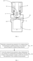
- FIG. 1 is a schematic structural diagram of a radiation measuring device according to an embodiment of this application.
- the radiation measuring device includes a radiation source 10, a radiation detector 20, at least two demarcation pieces 30, a drive assembly 40, and a control means 50.
- the radiation source 10 is configured to emit rays.
- a gap 101 is provided between the radiation detector 20 and the radiation source 10, where the gap 101 is configured to allow a workpiece being measured to pass, and the radiation detector 20 is configured to measure radiation intensity of received rays.
- Each of the at least two demarcation pieces 30 is capable of moving into the gap 101, and thickness varies with the demarcation piece.
- the drive assembly 40 is connected to the at least two demarcation pieces 30, and the drive assembly 40 is configured to drive at least one of the demarcation pieces separately to move into the gap 101.
- the control means 50 is electrically connected to the drive assembly 40, the radiation source 10, and the radiation detector 20.
- the control means 50 can obtain the radiation intensity of the rays measured by the radiation detector 20 after the rays have passed through the workpiece being measured, and then obtain a measured mass parameter of the workpiece being measured based on the radiation intensity and the radiation attenuation coefficient of the workpiece being measured; and ultimately, the measured mass parameter is corrected using a displacement curve function of the measurement environment in which the workpiece being measured is located to obtain the corrected mass parameter of the workpiece being measured, where the displacement curve function is obtained by demarcating at least two demarcation pieces 30 with rays, and the displacement curve function is used to characterize the influence of environmental factors on radiation transmittance in the measurement environment.
- the influence of the environmental factors on the radiation transmittance of rays is considered and the measured mass parameter is corrected using the displacement curve function, obtained by demarcation, during the measurement, so that the measured mass parameter is closer to or consistent with an actual mass parameter, improving the measurement accuracy; and moreover, the foregoing at least two demarcation pieces 30 being disposed in the gap 101 that is for the workpiece being measured to pass can implement demarcation in the measurement environment without the need for offline demarcation, making the demarcation more convenient and time-saving.
- the above control means 50 can control the drive assembly 40 to drive one or more demarcation pieces separately to move into the gap 101, so that the rays pass through multiple sets of demarcation pieces with different thicknesses during demarcation, and the radiation intensity of the rays after the rays have passed through the multiple sets of demarcation pieces with different thicknesses (that are, at least two demarcation pieces 30) is measured by the radiation detector 20.
- the mass calibration curve in the measurement environment is generated.
- the displacement curve function is obtained by fitting of the mass calibration curve under the measurement environment with the mass calibration curve in a predetermined standard environment.
- each demarcation piece set may contain only one demarcation piece.
- N may be an integer greater than or equal to 3 sets of demarcation pieces
- N demarcation pieces with different thicknesses can be configured in the above radiation measuring device, and the drive assembly 40 drives each of the N demarcation pieces separately to move into the above gap 101 to implement demarcation of each demarcation piece.
- each set of demarcation pieces may contain multiple demarcation pieces, that is, during demarcation, the drive assembly 40 may drive one or more of M (M may be an integer greater than or equal to 2) demarcation pieces to move into the gap 101; and when multiple demarcation pieces are driven to move into the gap 101, the rays may pass through the multiple demarcation pieces in sequence to implement demarcation of a demarcation piece set formed by combination of multiple demarcation pieces.
- M may be an integer greater than or equal to 2
- the radiation measuring device includes: a first demarcation piece 31 and a second demarcation piece 32, where the first demarcation piece 31 and the second demarcation piece 32 are spaced apart along a direction from the radiation source 10 to the radiation detector 20.
- the drive assembly 40 is configured to drive the first demarcation piece 31 and the second demarcation piece 32 separately to move into the gap 101, and drive the first demarcation piece 31 and the second demarcation piece 32 to move simultaneously into the gap 101 to form a third demarcation piece.
- the foregoing radiation measuring device may be provided with three or more demarcation pieces, and the drive assembly 40 can drive each demarcation piece to move into the gap 101 separately or simultaneously, so that more demarcation sets can be demarcated, thus making the generated mass calibration curve more accurate.
- the above radiation measuring device may further include a housing 60, and the radiation detector 20, the drive assembly 40, and the at least two demarcation pieces 30 are disposed in the housing 60.
- the housing 60 is provided with a through hole 102, where the through hole 102 is located between the radiation source 10 and the radiation detector 20.
- the rays emitted by the radiation source 10 can pass through the through hole 102 and be received by the radiation detector 20.
- Each of the at least two demarcation pieces 30 can be driven by the drive assembly 40 to the through hole 102, so that during demarcation, the rays enter the demarcation piece through the through hole 102, pass through the demarcation piece, and enter the detection receiver.
- the above drive assembly 40 may include at least two drive members.
- the at least two drive members correspond to the above at least two demarcation pieces 30, each drive member is connected to its corresponding demarcation piece, and each drive member is configured to drive its corresponding demarcation piece to move.
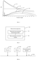
- FIG. 3 is a schematic flowchart of a measurement method according to an embodiment of this application and applied to the foregoing radiation measuring device. As shown in FIG. 3 , the method includes the following steps.
- Step 301 determining a measured mass parameter of a workpiece being measured based on radiation intensity of rays that have passed through the workpiece being measured.
- Step 302. correcting the measured mass parameter using a displacement curve function of the workpiece being measured in a measurement environment, to obtain the corrected mass parameter of the workpiece being measured, where the displacement curve function is used to characterize influence of environmental factors on radiation transmittance in the measurement environment.
- the measured mass parameter of the workpiece being measured is determined based on the radiation intensity of the rays that have passed through the workpiece being measured, and then the measured mass parameter is corrected using the displacement function of the measurement environment in which the workpiece being measured is located, where the displacement curve function is used to characterize the influence of the environmental factors on the radiation transmittance in the measurement environment.
- the influence of the environmental factors on the radiation transmittance of rays is considered and the measured mass parameter is corrected using the displacement curve function during the measurement, so that the measured mass parameter is closer to or consistent with an actual mass parameter, improving measurement accuracy.
- step 301 when the workpiece being measured moves into the gap between the radiation source and the radiation detector, the foregoing radiation measuring device can obtain the radiation intensity of the rays after the rays have passed through the workpiece being measured by measuring with the radiation detector.
- the above workpiece being measured may be any workpiece that requires measurement of at least one mass parameter such as thickness, weight, and surface density during production.
- the workpiece being measured may be a sheet or plate-shaped workpiece, such as aluminum foil or copper foil sheet.
- the above workpiece being measured may be a battery electrode plate during battery production, and furthermore, the workpiece being measured may be a battery electrode plate during coating.
- the radiation measuring device can obtain a measured mass parameter of the workpiece being measured based on the radiation intensity and the radiation attenuation coefficient of the workpiece being measured.
- the temperature in the measurement environment may be adjusted to the standard temperature and the pressure may be adjusted to the standard pressure, so that only contaminants such as dust or dirt in the measurement environment affect the radiation transmittance of the rays, and the deviation of the radiation transmittance in the environment in comparison with the radiation transmittance in the standard environment, is calculated to obtain the first initial displacement.
- Each of the above initial displacements may be calculated based on the radiation transmittance in a corresponding environment thereof and the radiation transmittance in the standard environment. For example, the ratio of the transmittance of the two is determined as the above initial displacement.
- the difference between the radiation transmittance under the environment corresponding to the initial displacement and the radiation transmittance under the standard environment being determined as the initial displacement makes the determined initial displacement more reasonable, thereby making the updated displacement curve function more accurately characterize the influence of each environmental factor on the radiation in the measurement environment, and further improving the measurement accuracy of the mass parameter.
- the above formula is used for obtaining each mass calibration curve so that the obtained mass calibration curve conforms to the Beer's law, thereby improving the accuracy of the mass calibration curve and thus further improving the accuracy of the measured mass parameter.
- the demarcating the at least two demarcation pieces in the measurement environment to obtain a mass calibration curve of the measurement environment includes: when a predetermined period is reached, demarcating the at least two demarcation pieces in the measurement environment to obtain a mass calibration curve of the measurement environment.
- the at least two demarcation pieces in the measurement environment are demarcated to obtain the mass calibration curve of the measurement environment, allowing timely updating of the displacement curve function, and thus making the measured mass parameter more precise.
- the workpiece being measured includes a battery electrode plate
- the mass parameter includes surface density of the battery electrode plate
- a measured surface density can be corrected during production of the battery electrode plate, so that the measured surface density is closer to or consistent with an actual surface density, improving the measurement accuracy of the surface density of the battery electrode plate.
- At least two demarcation pieces may be demarcated in the measurement environment to obtain a mass calibration curve 41 of the measurement environment, as shown in FIG. 4 .
- the mass calibration curve 41 and the mass calibration curve 42 are straight-line fitted to obtain a displacement curve 43 shown in FIG. 4 , which may be expressed by a function as a + bQ (that is, displacement curve function).
- the above displacement curve 43 has an inflection point A, that is, the displacement curve 43 may actually be expressed as a1 + b1Q as well as a2 + b2Q.
- the updated displacement curve function may be obtained using the above formula (4) and then the measured mass parameter may be updated, which may be realized by using following formula (5):
- Q Q 1 ⁇ 1 ⁇ log e I s I a ⁇ ⁇ R I s 0 I a 0
- FIG. 5 is a schematic structural diagram of a measurement apparatus according to an embodiment of this application. As shown in FIG. 5 , the apparatus 500 includes:
- the measured mass parameter of the workpiece being measured is determined based on the radiation intensity of the rays that have passed through the workpiece being measured, and then the measured mass parameter is corrected using the displacement function of the measurement environment in which the workpiece being measured is located, where the displacement curve function is used to characterize the influence of the environmental factors on the radiation transmittance in the measurement environment.
- the influence of the environmental factors on the radiation transmittance of rays is considered and the measured mass parameter is corrected using the displacement curve function during the measurement, so that the measured mass parameter is closer to or consistent with an actual mass parameter, improving measurement accuracy.
- the apparatus further includes:
- the above displacement curve function is obtained by fitting the mass calibration curve obtained by demarcation in the measurement environment with respect to the mass calibration curve obtained by measurement in the standard environment, so that the obtained displacement curve can better reflect influence of the measurement environment on the radiation transmittance, thus making the final determined mass parameter more accurate.
- the measurement environment is different from the standard environment in terms of contaminants as well as target influencing factors, the target influencing factors including environmental factors that cause a change in radiation transmittance other than the contaminants.
- the measurement environment is different from the standard environment in terms of both contaminants as well as target influencing factors, so that not only influence of the contaminants on the radiation transmittance is considered, but also influence of the target influencing factors on the radiation transmittance is considered, resulting in a more accurate corrected mass parameter.
- the apparatus 500 further includes:
- the first initial displacement generated under the influence of the contaminant in the measurement environment and the second initial displacement generated in the measurement environment are first obtained, then the ratio of the second initial displacement to the first initial displacement is calculated, and ultimately the displacement curve function is updated to the product of the fitted displacement curve function and the ratio, so that the generated displacement curve function takes into account both the influence of the contaminant on the radiation and also the influence of other factors on the radiation, which makes the determined displacement curve function more accurate and thus makes the measured mass parameter more precise.
- the difference between the radiation transmittance under the environment corresponding to the initial displacement and the radiation transmittance under the standard environment being determined as the initial displacement makes the determined initial displacement more reasonable, thereby making the updated displacement curve function more accurately characterize the influence of each environmental factor on the radiation in the measurement environment, and further improving the measurement accuracy of the mass parameter.
- the above formula is used for obtaining each mass calibration curve so that the obtained mass calibration curve conforms to the Beer's law, thereby improving the accuracy of the mass calibration curve and thus further improving the accuracy of the measured mass parameter.
- the mass calibration curve generation module is specifically configured to: when a predetermined period is reached, demarcate the at least two demarcation pieces in the measurement environment to obtain a mass calibration curve of the measurement environment.
- the at least two demarcation pieces in the measurement environment are demarcated to obtain the mass calibration curve of the measurement environment, allowing timely updating of the displacement curve function, and thus making the measured mass parameter more precise.
- the workpiece being measured includes a battery electrode plate
- the mass parameter includes surface density of the battery electrode plate
- a measured surface density can be corrected during production of the battery electrode plate, so that the measured surface density is closer to or consistent with an actual surface density, improving the measurement accuracy of the surface density of the battery electrode plate.
- the measurement apparatus has similar details as the measurement method described above in conjunction with the embodiment shown in FIG. 3 , and corresponding technical effects can be obtained. For brevity of description, details are not repeated herein.
- FIG. 6 is a schematic diagram of a hardware structure of a radiation measuring device according to an embodiment of this application.
- the radiation measuring device may include a processor 601 and a memory 602 that stores computer program instructions.
- the processor 601 may include a central processing unit (CPU), or an application specific integrated circuit (ASIC), or may be configured as one or more integrated circuits for implementing the embodiments of this application.
- CPU central processing unit
- ASIC application specific integrated circuit
- the memory 602 may include a mass memory for data or instructions.
- the memory 602 may include a hard disk drive (HDD), a floppy disk drive, a flash memory, an optical disk, a magnetic disk, a magnetic tape, a universal serial bus (USB) drive, or a combination of two or more thereof.
- the memory 602 may include removable or non-removable (or fixed) media, or the memory 602 is a nonvolatile solid state memory.
- the memory 602 may be located inside or outside a battery apparatus.
- the memory 602 may be a read only memory (ROM).
- the ROM may be a mask-programmed ROM, a programmable ROM (PROM), an erasable PROM (EPROM), an electrically erasable PROM (EEPROM), an electrically rewritable ROM (EAROM), a flash memory, or a combination of two or more thereof.
- the memory 602 may include a read-only memory (ROM), a random access memory (RAM), a disk storage media device, an optical storage media device, a flash memory device, or an electrical, optical or another physical/tangible memory storage device. Therefore, typically, the memory includes one or more tangible (non-transitory) computer-readable storage media (for example, a memory device) encoded with software including computer-executable instructions, and when the software is executed (for example, by one or more processors), the computer-readable storage media can perform the operations described with reference to the method according to one aspect of this disclosure.
- the processor 601 implements the method in the embodiment shown in FIG. 3 by reading and executing the computer program instructions stored in the memory 602, and achieves the corresponding technical effects, which are achieved in the embodiment shown in FIG. 3 by performing the method/steps thereof. For brevity of description, details are not repeated herein.
- the radiation measuring device may further include a communication interface 603 and a bus 604. As shown in FIG. 6 , the processor 601, the memory 602, and the communication interface 603 are connected and complete communication with each other via the bus 604.
- the communication interface 603 is mainly configured to implement communication between the modules, apparatuses, units, and/or devices in the embodiments of this application.
- the bus 604 includes hardware, software, or both, and couples the components of online data traffic billing devices to each other.
- the bus may include an accelerated graphics port (AGP) or other graphics buses, an enhanced industry standard architecture (EISA) bus, a front side bus (FSB), hyper transport (HT) interconnect, an industry standard architecture (ISA) bus, unlimited bandwidth interconnect, a low pin count (LPC) bus, a memory bus, a micro channel architecture (MCA) bus, a peripheral component interconnect (PCI) bus, a PCI-Express (PCI-X) bus, a serial advanced technology attachment (SATA) bus, a video electronics standards association local (VLB) bus, another suitable bus, or a combination of two or more thereof.
- the bus 604 may include one or more buses. Although specific buses are described and illustrated in the embodiments of this application, any suitable bus or interconnect are considered in this application.
- the radiation measuring device may perform the measurement method in the embodiments of this application, thereby implementing the measurement method and apparatus described in conjunction with FIGs. 3 and 4 .
- an embodiment of this application may provide a computer storage medium for implementation.
- the computer storage medium stores computer program instructions; and when the computer program instructions are executed by a processor, the measurement method according to any one of the foregoing embodiments is implemented.
Landscapes
- Chemical & Material Sciences (AREA)
- Physics & Mathematics (AREA)
- General Physics & Mathematics (AREA)
- General Health & Medical Sciences (AREA)
- Health & Medical Sciences (AREA)
- Pathology (AREA)
- Analytical Chemistry (AREA)
- Immunology (AREA)
- Biochemistry (AREA)
- Life Sciences & Earth Sciences (AREA)
- Chemical Kinetics & Catalysis (AREA)
- Electrochemistry (AREA)
- Crystallography & Structural Chemistry (AREA)
- Manufacturing & Machinery (AREA)
- General Chemical & Material Sciences (AREA)
- Engineering & Computer Science (AREA)
- Toxicology (AREA)
- Analysing Materials By The Use Of Radiation (AREA)
- Secondary Cells (AREA)
- Length-Measuring Devices Using Wave Or Particle Radiation (AREA)
Claims (15)
- Messverfahren zum Messen eines Massenparameters eines zu messenden Werkstücks, wobei das Verfahren Folgendes umfasst:Bestimmen (301) eines gemessenen Massenparameters des zu messenden Werkstücks basierend auf der Strahlungsintensität von Strahlen, die durch das zu messende Werkstück gelaufen sind;dadurch gekennzeichnet, dass das Verfahren ferner Folgendes umfasst:
Korrigieren (302) des gemessenen Massenparameters unter Verwendung einer Verschiebungskurvenfunktion des in einer Messumgebung zu messenden Werkstücks, um einen korrigierten Massenparameter des zu messenden Werkstücks zu erhalten, wobei die Verschiebungskurvenfunktion dazu verwendet wird, den Einfluss von Umgebungsfaktoren auf Strahlung in der Messumgebung zu kennzeichnen. - Verfahren nach Anspruch 1, ferner umfassend, vor dem Korrigieren (302) des gemessenen Massenparameters unter Verwendung einer Verschiebungskurvenfunktion des in einer Messumgebung zu messenden Werkstücks:Demarkieren von mindestens zwei Demarkierungsstücken in der Messumgebung, um eine Massenkalibrierungskurve der Messumgebung zu erhalten, wobei die Massenkalibrierungskurve dazu verwendet wird, eine Beziehung zwischen gemessenen Massenparametern und vorgegebenen nominellen Massenparametern jedes der Demarkierungsstücke zu kennzeichnen; undAnpassen der Massenkalibrierungskurve der Messumgebung in Bezug auf eine Massenkalibrierungskurve einer Standardumgebung, um die Verschiebungskurvenfunktion zu erhalten, wobei die Verschiebungskurvenfunktion dazu verwendet wird, einen Betrag der Änderung der Strahlungsdurchlässigkeit in der Messumgebung relativ zu der Standardumgebung zu kennzeichnen,wobei die Messumgebung vorzugsweise hinsichtlich Fremdstoffen sowie Zielbeeinflussungsfaktoren von der Standardumgebung verschieden ist, wobei die Zielbeeinflussungsfaktoren Umgebungsfaktoren außer den Fremdstoffen umfassen, die eine Änderung der Strahlungsdurchlässigkeit bewirken.
- Verfahren nach Anspruch 2, ferner umfassend:Erhalten einer ersten Anfangsverschiebung und einer zweiten Anfangsverschiebung durch Simulation, wobei die erste Anfangsverschiebung dazu verwendet wird, eine Abweichung der Strahlungsdurchlässigkeit nur unter dem Einfluss eines Fremdstoffs in der Messumgebung im Vergleich zu der Strahlungsdurchlässigkeit in der Standardumgebung zu kennzeichnen; und die zweite Anfangsverschiebung dazu verwendet wird, eine Abweichung der Strahlungsdurchlässigkeit in der Messumgebung im Vergleich zu der Strahlungsdurchlässigkeit in der Standardumgebung zu kennzeichnen; undAktualisieren der Verschiebungskurvenfunktion basierend auf einem Verhältnis der zweiten Anfangsverschiebung zu der ersten Anfangsverschiebung, wobei die aktualisierte Verschiebungskurvenfunktion ein Produkt von der Verschiebungskurvenfunktion vor der Aktualisierung und dem Verhältnis ist.
- Verfahren nach Anspruch 3, wobei die Anfangsverschiebungen jeweils unter Verwendung der folgenden Formel berechnet werden:
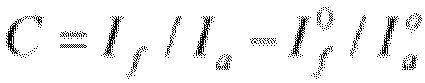 wobei C für die Anfangsverschiebung steht;If für eine nach dem Laufen der Strahlen durch das Demarkierungsstück in einer der Anfangsverschiebung entsprechenden Umgebung gemessene Strahlungsintensität steht;Ia für eine nach dem Laufen der Strahlen durch die Luft in der der Anfangsverschiebung entsprechenden Umgebung gemessene Strahlungsintensität steht;

und/oderwobei die Massenkalibrierungskurven jeweils unter Verwendung der folgenden Formel erhalten werden: wobei Q für einen basierend auf einer Strahlungsintensität und eines Strahlungsschwächungskoeffizienten der durch das Demarkierungsstück gelaufenen Strahlen berechneten gemessenen Massenparameter des Demarkierungsstücks steht;Q 1 für einen Ist-Massenparameter des Demarkierungsstücks steht;µ für den Strahlungsabschwächungskoeffizienten steht;Is für eine nach dem Laufen der Strahlen durch das Demarkierungsstück in einer der Massenkalibrierungskurve entsprechenden Umgebung gemessene Strahlungsintensität steht;Ia für eine nach dem Laufen der Strahlen durch die Luft in der der Massenkalibrierungskurve entsprechenden Umgebung gemessene Strahlungsintensität steht;

- Verfahren nach einem der Ansprüche 2 bis 4, wobei das Demarkieren von mindestens zwei Demarkierungsstücken in einer Messumgebung, um eine Massenkalibrierungskurve der Messumgebung zu erhalten, Folgendes umfasst:
wenn ein vorgegebener Zeitraum erreicht ist, Demarkieren der mindestens zwei Demarkierungsstücke in der Messumgebung, um eine Massenkalibrierungskurve der Messumgebung zu erhalten. - Verfahren nach einem der Ansprüche 1 bis 5, wobei das zu messende Werkstück eine Batterieelektrodenplatte umfasst und der Massenparameter eine Oberflächendichte der Batterieelektrodenplatte umfasst.
- Messvorrichtung (500), umfassend:ein Bestimmungsmodul (501) für einen gemessenen Massenparameter, das dazu konfiguriert ist, einen gemessenen Massenparameter eines zu messenden Werkstücks basierend auf der Strahlungsintensität von durch das zu messende Werkstück gelaufenen Strahlen zu bestimmen;dadurch gekennzeichnet, dass die Messvorrichtung (500) ferner Folgendes umfasst:
ein Massenparameter-Korrekturmodul (502) das dazu konfiguriert ist, den gemessenen Massenparameter unter Verwendung einer Verschiebungskurvenfunktion des in einer Messumgebung zu messenden Werkstücks zu korrigieren, um einen korrigierten Massenparameter des zu messenden Werkstücks zu erhalten, wobei die Verschiebungskurvenfunktion dazu verwendet wird, den Einfluss von Umgebungsfaktoren auf die Strahlung in der Messumgebung zu kennzeichnen. - Vorrichtung (500) nach Anspruch 7, ferner umfassend:ein Massenkalibrierungskurven-Erzeugungsmodul, das dazu konfiguriert ist, mindestens zwei Demarkierungsstücke (30) in einer Messumgebung zu demarkieren, um eine Massenkalibrierungskurve (41) der Messumgebung zu erhalten, wobei die Massenkalibrierungskurve (41) dazu verwendet wird, eine Beziehung zwischen gemessenen Massenparametern und vorgegebenen nominellen Massenparametern jedes der Demarkierungsstücke (30) zu kennzeichnen; undein Verschiebungskurvenfunktions-Erzeugungsmodul, das dazu konfiguriert ist, die Massenkalibrierungskurve (41) der Messumgebung in Bezug auf eine Massenkalibrierungskurve (42) einer Standardumgebung anzupassen, um die Verschiebungskurvenfunktion zu erhalten, wobei die Verschiebungskurvenfunktion dazu verwendet wird, einen Betrag der Änderung der Strahlungsdurchlässigkeit in der Messumgebung relativ zu der Standardumgebung zu kennzeichnen,wobei die Messumgebung vorzugsweise hinsichtlich Fremdstoffen sowie Zielbeeinflussungsfaktoren von der Standardumgebung verschieden ist, wobei die Zielbeeinflussungsfaktoren Umgebungsfaktoren außer den Fremdstoffen umfassen, die eine Änderung der Strahlungsdurchlässigkeit bewirken, undwobei das Massenkalibrierungskurven-Erzeugungsmodul vorzugsweise speziell dazu konfiguriert ist, wenn ein vorgegebener Zeitraum erreicht ist, die mindestens zwei Demarkierungsstücke (30) in der Messumgebung zu demarkieren, um eine Massenkalibrierungskurve (41) der Messumgebung zu erhalten.
- Vorrichtung (500) nach Anspruch 8, ferner umfassend:ein Simulationsmodul, das dazu konfiguriert ist, eine erste Anfangsverschiebung und eine zweite Anfangsverschiebung durch Simulation zu erhalten, wobei die erste Anfangsverschiebung dazu verwendet wird, eine Abweichung der Strahlungsdurchlässigkeit nur unter dem Einfluss eines Fremdstoffs in der Messumgebung im Vergleich zu der Strahlungsdurchlässigkeit in der Standardumgebung zu kennzeichnen; und die zweite Anfangsverschiebung dazu verwendet wird, eine Abweichung der Strahlungsdurchlässigkeit in der Messumgebung im Vergleich zu der Strahlungsdurchlässigkeit in der Standardumgebung zu kennzeichnen; undein Verschiebungskurvenfunktions-Aktualisierungsmodul, das dazu konfiguriert ist, die Verschiebungskurvenfunktion basierend auf einem Verhältnis der zweiten Anfangsverschiebung zu der ersten Anfangsverschiebung zu aktualisieren, wobei die aktualisierte Verschiebungskurvenfunktion ein Produkt von der Verschiebungskurvenfunktion vor der Aktualisierung und dem Verhältnis ist.
- Vorrichtung (500) Verfahren nach Anspruch 9, wobei die Anfangsverschiebungen jeweils unter Verwendung der folgenden Formel berechnet werden:
 wobei C für die Anfangsverschiebung steht;If für eine nach dem Laufen der Strahlen durch das Demarkierungsstück (30) in einer der Anfangsverschiebung entsprechenden Umgebung gemessene Strahlungsintensität steht;Ia für eine nach dem Laufen der Strahlen durch die Luft in der der Anfangsverschiebung entsprechenden Umgebung gemessene Strahlungsintensität steht;

und/oderwobei die Massenkalibrierungskurven jeweils unter Verwendung der folgenden Formel erhalten werden: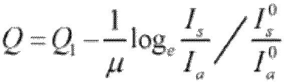 wobei Q für einen basierend auf einer Strahlungsintensität und eines Strahlungsschwächungskoeffizienten der durch das Demarkierungsstück (30) gelaufenen Strahlen berechneten gemessenen Massenparameter des Demarkierungsstücks (30) steht;Q1 für einen Ist-Massenparameter des Demarkierungsstücks (30) steht;µ für den Strahlungsabschwächungskoeffizienten steht;Is für eine nach dem Laufen der Strahlen durch das Demarkierungsstück (30) in einer der Massenkalibrierungskurve entsprechenden Umgebung gemessene Strahlungsintensität steht;Ia für eine nach dem Laufen der Strahlen durch die Luft in der der Massenkalibrierungskurve entsprechenden Umgebung gemessene Strahlungsintensität steht;

- Vorrichtung (500) nach einem der Ansprüche 7 bis 10, wobei das zu messende Werkstück eine Batterieelektrodenplatte umfasst und der Massenparameter eine Oberflächendichte der Batterieelektrodenplatte umfasst.
- Strahlungsmessvorrichtung, umfassend:eine Strahlungsquelle (10);einen Strahlungsdetektor (20), wobei zwischen dem Strahlungsdetektor (20) und der Strahlungsquelle (10) ein Zwischenraum (101) bereitgestellt ist und der Zwischenraum (10) dazu konfiguriert ist, ein zu messendes Werkstück hindurchgelangen zu lassen;mindestens zwei Demarkierungsstücke (30), wobei die Demarkierungsstücke (30) jeweils in der Lage sind, sich in den Zwischenraum (101) zu bewegen, und sich die Dicke mit dem Demarkierungsstück (30) verändert;eine Antriebsanordnung (40), wobei die Antriebsanordnung (40) mit den mindestens zwei Demarkierungsstücken (30) verbunden ist und die Antriebsanordnung (40) dazu konfiguriert ist, mindestens eines der Demarkierungsstücke (30) dazu anzutreiben, sich in den Zwischenraum (101) zu bewegen; undein Steuermittel (50), das mit der Antriebsanordnung (40), der Strahlungsquelle (10) und dem Strahlungsdetektor (20) elektrisch verbunden ist, wobei das Steuermittel (50) die Messvorrichtung (500) nach Anspruch 7 umfasst.
- Vorrichtung nach Anspruch 12, umfassend:ein erstes Demarkierungsstück (31) und ein zweites Demarkierungsstück (32), wobei das erste Demarkierungsstück (31) und das zweite Demarkierungsstück (32) entlang einer Richtung von der Strahlungsquelle (10) zu dem Strahlungsdetektor (20) voneinander beabstandet sind; undwobei die Antriebanordnung (40) dazu konfiguriert ist, das erste Demarkierungsstück (31) und das zweite Demarkierungsstück (32) getrennt dazu anzutreiben, sich in den Zwischenraum (101) zu bewegen, und das erste Demarkierungsstück (31) und das zweite Demarkierungsstück (32) dazu anzutreiben, sich gleichzeitig in den Zwischenraum (101) zu bewegen, um ein drittes Demarkierungsstück zu bilden.
- Strahlungsmessvorrichtung nach Anspruch 12, umfassend einen Prozessor (601), einen Speicher (602) und ein Programm oder Anweisungen, das bzw. die in dem Speicher (602) gespeichert sind und in der Lage sind, auf dem Prozessor (601) zu laufen, wobei, wenn das Programm oder die Anweisungen von dem Prozessor (601) ausgeführt werden, die Schritte des Messverfahrens nach einem der Ansprüche 1 bis 6 implementiert werden.
- Lesbares Speichermedium, umfassend ein Programm oder Anweisungen, das bzw. die, wenn sie von einem Prozessor (601) ausgeführt werden, zu der Durchführung der Schritte des Messverfahrens nach einem der Ansprüche 1 bis 6 führen.
Applications Claiming Priority (2)
| Application Number | Priority Date | Filing Date | Title |
|---|---|---|---|
| CN202210575858.5A CN117168370A (zh) | 2022-05-25 | 2022-05-25 | 测量方法、装置及射线测量设备 |
| PCT/CN2023/095012 WO2023226867A1 (zh) | 2022-05-25 | 2023-05-18 | 测量方法、装置及射线测量设备 |
Publications (4)
| Publication Number | Publication Date |
|---|---|
| EP4307014A1 EP4307014A1 (de) | 2024-01-17 |
| EP4307014A4 EP4307014A4 (de) | 2024-05-01 |
| EP4307014B1 true EP4307014B1 (de) | 2025-04-23 |
| EP4307014C0 EP4307014C0 (de) | 2025-04-23 |
Family
ID=88147188
Family Applications (1)
| Application Number | Title | Priority Date | Filing Date |
|---|---|---|---|
| EP23768103.6A Active EP4307014B1 (de) | 2022-05-25 | 2023-05-18 | Messverfahren, vorrichtung und strahlungsmessvorrichtung |
Country Status (7)
| Country | Link |
|---|---|
| US (1) | US12442778B2 (de) |
| EP (1) | EP4307014B1 (de) |
| CN (1) | CN117168370A (de) |
| ES (1) | ES3035434T3 (de) |
| HU (1) | HUE072218T2 (de) |
| PL (1) | PL4307014T3 (de) |
| WO (1) | WO2023226867A1 (de) |
Families Citing this family (1)
| Publication number | Priority date | Publication date | Assignee | Title |
|---|---|---|---|---|
| CN118584525B (zh) * | 2024-08-02 | 2024-10-29 | 陕西正泽生物技术有限公司 | 一种基于区域辐射监测仪的辐射监测方法及系统 |
Family Cites Families (11)
| Publication number | Priority date | Publication date | Assignee | Title |
|---|---|---|---|---|
| US3681595A (en) * | 1970-04-03 | 1972-08-01 | Measurex Corp | Basis weight gauge standardizing system |
| US4692616A (en) * | 1984-03-14 | 1987-09-08 | Measurex Corporation | Basis weight gauge standardizing method and system |
| US4803715A (en) * | 1986-10-10 | 1989-02-07 | Process Automation Business, Inc. | Thickness measurement with automatic correction for changes in composition |
| BRPI0618680B1 (pt) * | 2005-11-16 | 2018-06-05 | Ishida Co., Ltd. | Dispositivo para inspeção por raio-x |
| CN103206931B (zh) * | 2013-03-07 | 2015-10-21 | 重庆大学 | 一种x射线测厚方法及装置 |
| CN104475462B (zh) * | 2014-11-24 | 2016-08-24 | 北京金自天正智能控制股份有限公司 | 一种x射线测厚仪的在线校正装置及方法 |
| DE102017130534B4 (de) * | 2017-12-19 | 2020-12-03 | Endress+Hauser SE+Co. KG | Verfahren zum Kalibrieren einer radiometrischen Dichte-Messvorrichtung |
| CN209326587U (zh) | 2019-01-30 | 2019-08-30 | 佛山市宗生科技有限公司 | 一种采用射线的自动标定装置 |
| CN110031359A (zh) * | 2019-04-08 | 2019-07-19 | 深圳鸿鹏新能源科技有限公司 | 面密度测量仪的标定方法 |
| CN110231005B (zh) * | 2019-06-27 | 2021-04-13 | 江苏同威信达技术有限公司 | 一种物品质量厚度检测方法及物品质量厚度检测装置 |
| CN112033983A (zh) * | 2020-08-13 | 2020-12-04 | 上海瑞示电子科技有限公司 | 一种x射线发射系统及检测系统 |
-
2022
- 2022-05-25 CN CN202210575858.5A patent/CN117168370A/zh active Pending
-
2023
- 2023-05-18 HU HUE23768103A patent/HUE072218T2/hu unknown
- 2023-05-18 ES ES23768103T patent/ES3035434T3/es active Active
- 2023-05-18 WO PCT/CN2023/095012 patent/WO2023226867A1/zh not_active Ceased
- 2023-05-18 EP EP23768103.6A patent/EP4307014B1/de active Active
- 2023-05-18 PL PL23768103.6T patent/PL4307014T3/pl unknown
- 2023-10-03 US US18/479,898 patent/US12442778B2/en active Active
Also Published As
| Publication number | Publication date |
|---|---|
| WO2023226867A1 (zh) | 2023-11-30 |
| PL4307014T3 (pl) | 2025-08-11 |
| EP4307014A1 (de) | 2024-01-17 |
| HUE072218T2 (hu) | 2025-10-28 |
| CN117168370A (zh) | 2023-12-05 |
| US20240027368A1 (en) | 2024-01-25 |
| ES3035434T3 (en) | 2025-09-03 |
| EP4307014C0 (de) | 2025-04-23 |
| US12442778B2 (en) | 2025-10-14 |
| EP4307014A4 (de) | 2024-05-01 |
Similar Documents
| Publication | Publication Date | Title |
|---|---|---|
| US9151595B1 (en) | Laser thickness gauge and method including passline angle correction | |
| CN103954297B (zh) | 一种光学遥感卫星图像定位精度确定方法 | |
| EP3501828B1 (de) | Leiterplatteninspektionsvorrichtung, verfahren zur erkennung einer anomalie in lotpaste und computerlesbares aufzeichnungsmedium | |
| EP4307014B1 (de) | Messverfahren, vorrichtung und strahlungsmessvorrichtung | |
| CN113741343B (zh) | 一种机床双轴同步控制方法、系统和机床 | |
| CN104475462A (zh) | 一种x射线测厚仪的在线校正装置及方法 | |
| CN102650602A (zh) | 放射线检查装置 | |
| US20250131578A1 (en) | Wafer defect detection method, device, electron-beam scanning device and storage medium | |
| CN115962739A (zh) | X射线测厚仪的校准方法、装置、存储介质及电子设备 | |
| CN108762181A (zh) | 汽车仪表指针调校方法 | |
| CN115646761A (zh) | 一种涂布面密度在线检测方法、装置及电池涂布设备 | |
| CN116026263B (zh) | 测厚校准方法、装置、设备和存储介质 | |
| Pueo et al. | Measurement uncertainty evaluation model in radial composite gear inspection | |
| CN104036834A (zh) | 一种次临界系统次临界度的测量方法 | |
| KR102007241B1 (ko) | 표준 절연유의 가스 분석값 보정 시스템 및 방법 | |
| CN104801549A (zh) | 冷轧带钢板形仪信号失真通道的数据处理方法 | |
| CN110849827B (zh) | 中阶梯光谱仪的光谱定标方法、装置、设备及存储介质 | |
| CN104457622A (zh) | 一种长轴内孔直线度检测装置及其检测方法 | |
| CN104155983B (zh) | 飞行器姿态运动通道间气动耦合特性的交联影响确定方法 | |
| CN111505703A (zh) | 钚物质的钚质量测量方法、装置、设备及介质 | |
| CN108180934B (zh) | 一种光纤传感装置的检测装置及检测方法 | |
| CN112115622B (zh) | 一种融合实测数据的辐射剂量场分布评估方法及系统 | |
| CN110057330B (zh) | 一种线宽测量方法和线宽测量系统 | |
| US11859965B2 (en) | Material analysis method | |
| Sekatskii et al. | Analysis of Techniques for Verification of Coating Thickness Gauges |
Legal Events
| Date | Code | Title | Description |
|---|---|---|---|
| STAA | Information on the status of an ep patent application or granted ep patent |
Free format text: STATUS: UNKNOWN |
|
| STAA | Information on the status of an ep patent application or granted ep patent |
Free format text: STATUS: THE INTERNATIONAL PUBLICATION HAS BEEN MADE |
|
| PUAI | Public reference made under article 153(3) epc to a published international application that has entered the european phase |
Free format text: ORIGINAL CODE: 0009012 |
|
| STAA | Information on the status of an ep patent application or granted ep patent |
Free format text: STATUS: REQUEST FOR EXAMINATION WAS MADE |
|
| 17P | Request for examination filed |
Effective date: 20230919 |
|
| AK | Designated contracting states |
Kind code of ref document: A1 Designated state(s): AL AT BE BG CH CY CZ DE DK EE ES FI FR GB GR HR HU IE IS IT LI LT LU LV MC ME MK MT NL NO PL PT RO RS SE SI SK SM TR |
|
| A4 | Supplementary search report drawn up and despatched |
Effective date: 20240403 |
|
| RIC1 | Information provided on ipc code assigned before grant |
Ipc: G01G 9/00 20060101ALI20240326BHEP Ipc: G01N 23/00 20060101ALI20240326BHEP Ipc: G01T 1/00 20060101AFI20240326BHEP |
|
| STAA | Information on the status of an ep patent application or granted ep patent |
Free format text: STATUS: EXAMINATION IS IN PROGRESS |
|
| 17Q | First examination report despatched |
Effective date: 20240822 |
|
| RAP1 | Party data changed (applicant data changed or rights of an application transferred) |
Owner name: CONTEMPORARY AMPEREX TECHNOLOGY(HONG KONG) LIMITED |
|
| GRAP | Despatch of communication of intention to grant a patent |
Free format text: ORIGINAL CODE: EPIDOSNIGR1 |
|
| STAA | Information on the status of an ep patent application or granted ep patent |
Free format text: STATUS: GRANT OF PATENT IS INTENDED |
|
| DAV | Request for validation of the european patent (deleted) | ||
| DAX | Request for extension of the european patent (deleted) | ||
| INTG | Intention to grant announced |
Effective date: 20250207 |
|
| GRAS | Grant fee paid |
Free format text: ORIGINAL CODE: EPIDOSNIGR3 |
|
| GRAA | (expected) grant |
Free format text: ORIGINAL CODE: 0009210 |
|
| STAA | Information on the status of an ep patent application or granted ep patent |
Free format text: STATUS: THE PATENT HAS BEEN GRANTED |
|
| AK | Designated contracting states |
Kind code of ref document: B1 Designated state(s): AL AT BE BG CH CY CZ DE DK EE ES FI FR GB GR HR HU IE IS IT LI LT LU LV MC ME MK MT NL NO PL PT RO RS SE SI SK SM TR |
|
| REG | Reference to a national code |
Ref country code: GB Ref legal event code: FG4D |
|
| REG | Reference to a national code |
Ref country code: CH Ref legal event code: EP |
|
| REG | Reference to a national code |
Ref country code: DE Ref legal event code: R096 Ref document number: 602023003098 Country of ref document: DE |
|
| REG | Reference to a national code |
Ref country code: IE Ref legal event code: FG4D |
|
| U01 | Request for unitary effect filed |
Effective date: 20250519 |
|
| U07 | Unitary effect registered |
Designated state(s): AT BE BG DE DK EE FI FR IT LT LU LV MT NL PT RO SE SI Effective date: 20250526 |
|
| U20 | Renewal fee for the european patent with unitary effect paid |
Year of fee payment: 3 Effective date: 20250522 |
|
| PGFP | Annual fee paid to national office [announced via postgrant information from national office to epo] |
Ref country code: ES Payment date: 20250602 Year of fee payment: 3 |
|
| REG | Reference to a national code |
Ref country code: ES Ref legal event code: FG2A Ref document number: 3035434 Country of ref document: ES Kind code of ref document: T3 Effective date: 20250903 |
|
| PG25 | Lapsed in a contracting state [announced via postgrant information from national office to epo] |
Ref country code: NO Free format text: LAPSE BECAUSE OF FAILURE TO SUBMIT A TRANSLATION OF THE DESCRIPTION OR TO PAY THE FEE WITHIN THE PRESCRIBED TIME-LIMIT Effective date: 20250723 Ref country code: GR Free format text: LAPSE BECAUSE OF FAILURE TO SUBMIT A TRANSLATION OF THE DESCRIPTION OR TO PAY THE FEE WITHIN THE PRESCRIBED TIME-LIMIT Effective date: 20250724 |
|
| PGFP | Annual fee paid to national office [announced via postgrant information from national office to epo] |
Ref country code: PL Payment date: 20250428 Year of fee payment: 3 |
|
| PGFP | Annual fee paid to national office [announced via postgrant information from national office to epo] |
Ref country code: HU Payment date: 20250430 Year of fee payment: 3 |
|
| PG25 | Lapsed in a contracting state [announced via postgrant information from national office to epo] |
Ref country code: HR Free format text: LAPSE BECAUSE OF FAILURE TO SUBMIT A TRANSLATION OF THE DESCRIPTION OR TO PAY THE FEE WITHIN THE PRESCRIBED TIME-LIMIT Effective date: 20250423 |
|
| PG25 | Lapsed in a contracting state [announced via postgrant information from national office to epo] |
Ref country code: RS Free format text: LAPSE BECAUSE OF FAILURE TO SUBMIT A TRANSLATION OF THE DESCRIPTION OR TO PAY THE FEE WITHIN THE PRESCRIBED TIME-LIMIT Effective date: 20250723 |
|
| PG25 | Lapsed in a contracting state [announced via postgrant information from national office to epo] |
Ref country code: IS Free format text: LAPSE BECAUSE OF FAILURE TO SUBMIT A TRANSLATION OF THE DESCRIPTION OR TO PAY THE FEE WITHIN THE PRESCRIBED TIME-LIMIT Effective date: 20250823 |
|
| REG | Reference to a national code |
Ref country code: HU Ref legal event code: AG4A Ref document number: E072218 Country of ref document: HU |
|
| PG25 | Lapsed in a contracting state [announced via postgrant information from national office to epo] |
Ref country code: SM Free format text: LAPSE BECAUSE OF FAILURE TO SUBMIT A TRANSLATION OF THE DESCRIPTION OR TO PAY THE FEE WITHIN THE PRESCRIBED TIME-LIMIT Effective date: 20250423 |
|
| PG25 | Lapsed in a contracting state [announced via postgrant information from national office to epo] |
Ref country code: CZ Free format text: LAPSE BECAUSE OF FAILURE TO SUBMIT A TRANSLATION OF THE DESCRIPTION OR TO PAY THE FEE WITHIN THE PRESCRIBED TIME-LIMIT Effective date: 20250423 |
|
| PG25 | Lapsed in a contracting state [announced via postgrant information from national office to epo] |
Ref country code: SK Free format text: LAPSE BECAUSE OF FAILURE TO SUBMIT A TRANSLATION OF THE DESCRIPTION OR TO PAY THE FEE WITHIN THE PRESCRIBED TIME-LIMIT Effective date: 20250423 |
|
| PG25 | Lapsed in a contracting state [announced via postgrant information from national office to epo] |
Ref country code: MC Free format text: LAPSE BECAUSE OF FAILURE TO SUBMIT A TRANSLATION OF THE DESCRIPTION OR TO PAY THE FEE WITHIN THE PRESCRIBED TIME-LIMIT Effective date: 20250423 |