EP4306293B1 - Durch vakuumformen hergestellte protrusionsschale - Google Patents
Durch vakuumformen hergestellte protrusionsschale Download PDFInfo
- Publication number
- EP4306293B1 EP4306293B1 EP23185686.5A EP23185686A EP4306293B1 EP 4306293 B1 EP4306293 B1 EP 4306293B1 EP 23185686 A EP23185686 A EP 23185686A EP 4306293 B1 EP4306293 B1 EP 4306293B1
- Authority
- EP
- European Patent Office
- Prior art keywords
- protrusion
- vacuum forming
- product
- mold
- forming
- Prior art date
- Legal status (The legal status is an assumption and is not a legal conclusion. Google has not performed a legal analysis and makes no representation as to the accuracy of the status listed.)
- Active
Links
Images



Classifications
-
- B—PERFORMING OPERATIONS; TRANSPORTING
- B65—CONVEYING; PACKING; STORING; HANDLING THIN OR FILAMENTARY MATERIAL
- B65D—CONTAINERS FOR STORAGE OR TRANSPORT OF ARTICLES OR MATERIALS, e.g. BAGS, BARRELS, BOTTLES, BOXES, CANS, CARTONS, CRATES, DRUMS, JARS, TANKS, HOPPERS, FORWARDING CONTAINERS; ACCESSORIES, CLOSURES, OR FITTINGS THEREFOR; PACKAGING ELEMENTS; PACKAGES
- B65D1/00—Rigid or semi-rigid containers having bodies formed in one piece, e.g. by casting metallic material, by moulding plastics, by blowing vitreous material, by throwing ceramic material, by moulding pulped fibrous material or by deep-drawing operations performed on sheet material
- B65D1/34—Trays or like shallow containers
- B65D1/36—Trays or like shallow containers with moulded compartments or partitions
-
- B—PERFORMING OPERATIONS; TRANSPORTING
- B29—WORKING OF PLASTICS; WORKING OF SUBSTANCES IN A PLASTIC STATE IN GENERAL
- B29C—SHAPING OR JOINING OF PLASTICS; SHAPING OF MATERIAL IN A PLASTIC STATE, NOT OTHERWISE PROVIDED FOR; AFTER-TREATMENT OF THE SHAPED PRODUCTS, e.g. REPAIRING
- B29C51/00—Shaping by thermoforming, i.e. shaping sheets or sheet like preforms after heating, e.g. shaping sheets in matched moulds or by deep-drawing; Apparatus therefor
- B29C51/10—Forming by pressure difference, e.g. vacuum
-
- B—PERFORMING OPERATIONS; TRANSPORTING
- B29—WORKING OF PLASTICS; WORKING OF SUBSTANCES IN A PLASTIC STATE IN GENERAL
- B29C—SHAPING OR JOINING OF PLASTICS; SHAPING OF MATERIAL IN A PLASTIC STATE, NOT OTHERWISE PROVIDED FOR; AFTER-TREATMENT OF THE SHAPED PRODUCTS, e.g. REPAIRING
- B29C51/00—Shaping by thermoforming, i.e. shaping sheets or sheet like preforms after heating, e.g. shaping sheets in matched moulds or by deep-drawing; Apparatus therefor
- B29C51/26—Component parts, details or accessories; Auxiliary operations
- B29C51/30—Moulds
- B29C51/34—Moulds for undercut articles
-
- B—PERFORMING OPERATIONS; TRANSPORTING
- B29—WORKING OF PLASTICS; WORKING OF SUBSTANCES IN A PLASTIC STATE IN GENERAL
- B29C—SHAPING OR JOINING OF PLASTICS; SHAPING OF MATERIAL IN A PLASTIC STATE, NOT OTHERWISE PROVIDED FOR; AFTER-TREATMENT OF THE SHAPED PRODUCTS, e.g. REPAIRING
- B29C51/00—Shaping by thermoforming, i.e. shaping sheets or sheet like preforms after heating, e.g. shaping sheets in matched moulds or by deep-drawing; Apparatus therefor
- B29C51/26—Component parts, details or accessories; Auxiliary operations
- B29C51/30—Moulds
- B29C51/36—Moulds specially adapted for vacuum forming, Manufacture thereof
-
- B—PERFORMING OPERATIONS; TRANSPORTING
- B29—WORKING OF PLASTICS; WORKING OF SUBSTANCES IN A PLASTIC STATE IN GENERAL
- B29C—SHAPING OR JOINING OF PLASTICS; SHAPING OF MATERIAL IN A PLASTIC STATE, NOT OTHERWISE PROVIDED FOR; AFTER-TREATMENT OF THE SHAPED PRODUCTS, e.g. REPAIRING
- B29C51/00—Shaping by thermoforming, i.e. shaping sheets or sheet like preforms after heating, e.g. shaping sheets in matched moulds or by deep-drawing; Apparatus therefor
- B29C51/26—Component parts, details or accessories; Auxiliary operations
- B29C51/44—Removing or ejecting moulded articles
-
- B—PERFORMING OPERATIONS; TRANSPORTING
- B65—CONVEYING; PACKING; STORING; HANDLING THIN OR FILAMENTARY MATERIAL
- B65D—CONTAINERS FOR STORAGE OR TRANSPORT OF ARTICLES OR MATERIALS, e.g. BAGS, BARRELS, BOTTLES, BOXES, CANS, CARTONS, CRATES, DRUMS, JARS, TANKS, HOPPERS, FORWARDING CONTAINERS; ACCESSORIES, CLOSURES, OR FITTINGS THEREFOR; PACKAGING ELEMENTS; PACKAGES
- B65D19/00—Pallets or like platforms, with or without side walls, for supporting loads to be lifted or lowered
- B65D19/38—Details or accessories
-
- B—PERFORMING OPERATIONS; TRANSPORTING
- B65—CONVEYING; PACKING; STORING; HANDLING THIN OR FILAMENTARY MATERIAL
- B65D—CONTAINERS FOR STORAGE OR TRANSPORT OF ARTICLES OR MATERIALS, e.g. BAGS, BARRELS, BOTTLES, BOXES, CANS, CARTONS, CRATES, DRUMS, JARS, TANKS, HOPPERS, FORWARDING CONTAINERS; ACCESSORIES, CLOSURES, OR FITTINGS THEREFOR; PACKAGING ELEMENTS; PACKAGES
- B65D21/00—Nestable, stackable or joinable containers; Containers of variable capacity
- B65D21/02—Containers specially shaped, or provided with fittings or attachments, to facilitate nesting, stacking, or joining together
- B65D21/0209—Containers specially shaped, or provided with fittings or attachments, to facilitate nesting, stacking, or joining together stackable or joined together one-upon-the-other in the upright or upside-down position
- B65D21/0215—Containers with stacking feet or corner elements
-
- B—PERFORMING OPERATIONS; TRANSPORTING
- B65—CONVEYING; PACKING; STORING; HANDLING THIN OR FILAMENTARY MATERIAL
- B65D—CONTAINERS FOR STORAGE OR TRANSPORT OF ARTICLES OR MATERIALS, e.g. BAGS, BARRELS, BOTTLES, BOXES, CANS, CARTONS, CRATES, DRUMS, JARS, TANKS, HOPPERS, FORWARDING CONTAINERS; ACCESSORIES, CLOSURES, OR FITTINGS THEREFOR; PACKAGING ELEMENTS; PACKAGES
- B65D21/00—Nestable, stackable or joinable containers; Containers of variable capacity
- B65D21/02—Containers specially shaped, or provided with fittings or attachments, to facilitate nesting, stacking, or joining together
- B65D21/0209—Containers specially shaped, or provided with fittings or attachments, to facilitate nesting, stacking, or joining together stackable or joined together one-upon-the-other in the upright or upside-down position
- B65D21/023—Closed containers provided with local cooperating elements in the top and bottom surfaces, e.g. projection and recess
-
- B—PERFORMING OPERATIONS; TRANSPORTING
- B29—WORKING OF PLASTICS; WORKING OF SUBSTANCES IN A PLASTIC STATE IN GENERAL
- B29C—SHAPING OR JOINING OF PLASTICS; SHAPING OF MATERIAL IN A PLASTIC STATE, NOT OTHERWISE PROVIDED FOR; AFTER-TREATMENT OF THE SHAPED PRODUCTS, e.g. REPAIRING
- B29C2791/00—Shaping characteristics in general
- B29C2791/004—Shaping under special conditions
- B29C2791/006—Using vacuum
-
- B—PERFORMING OPERATIONS; TRANSPORTING
- B29—WORKING OF PLASTICS; WORKING OF SUBSTANCES IN A PLASTIC STATE IN GENERAL
- B29C—SHAPING OR JOINING OF PLASTICS; SHAPING OF MATERIAL IN A PLASTIC STATE, NOT OTHERWISE PROVIDED FOR; AFTER-TREATMENT OF THE SHAPED PRODUCTS, e.g. REPAIRING
- B29C33/00—Moulds or cores; Details thereof or accessories therefor
- B29C33/44—Moulds or cores; Details thereof or accessories therefor with means for, or specially constructed to facilitate, the removal of articles, e.g. of undercut articles
- B29C33/442—Moulds or cores; Details thereof or accessories therefor with means for, or specially constructed to facilitate, the removal of articles, e.g. of undercut articles with mechanical ejector or drive means therefor
-
- B—PERFORMING OPERATIONS; TRANSPORTING
- B29—WORKING OF PLASTICS; WORKING OF SUBSTANCES IN A PLASTIC STATE IN GENERAL
- B29L—INDEXING SCHEME ASSOCIATED WITH SUBCLASS B29C, RELATING TO PARTICULAR ARTICLES
- B29L2007/00—Flat articles, e.g. films or sheets
-
- B—PERFORMING OPERATIONS; TRANSPORTING
- B29—WORKING OF PLASTICS; WORKING OF SUBSTANCES IN A PLASTIC STATE IN GENERAL
- B29L—INDEXING SCHEME ASSOCIATED WITH SUBCLASS B29C, RELATING TO PARTICULAR ARTICLES
- B29L2031/00—Other particular articles
- B29L2031/712—Containers; Packaging elements or accessories, Packages
- B29L2031/7162—Boxes, cartons, cases
-
- B—PERFORMING OPERATIONS; TRANSPORTING
- B29—WORKING OF PLASTICS; WORKING OF SUBSTANCES IN A PLASTIC STATE IN GENERAL
- B29L—INDEXING SCHEME ASSOCIATED WITH SUBCLASS B29C, RELATING TO PARTICULAR ARTICLES
- B29L2031/00—Other particular articles
- B29L2031/712—Containers; Packaging elements or accessories, Packages
- B29L2031/7178—Pallets
-
- Y—GENERAL TAGGING OF NEW TECHNOLOGICAL DEVELOPMENTS; GENERAL TAGGING OF CROSS-SECTIONAL TECHNOLOGIES SPANNING OVER SEVERAL SECTIONS OF THE IPC; TECHNICAL SUBJECTS COVERED BY FORMER USPC CROSS-REFERENCE ART COLLECTIONS [XRACs] AND DIGESTS
- Y02—TECHNOLOGIES OR APPLICATIONS FOR MITIGATION OR ADAPTATION AGAINST CLIMATE CHANGE
- Y02E—REDUCTION OF GREENHOUSE GAS [GHG] EMISSIONS, RELATED TO ENERGY GENERATION, TRANSMISSION OR DISTRIBUTION
- Y02E60/00—Enabling technologies; Technologies with a potential or indirect contribution to GHG emissions mitigation
- Y02E60/10—Energy storage using batteries
Definitions
- One or more embodiments relate to a protrusion tray manufactured by vacuum forming, and more particularly, to a protrusion tray manufactured by vacuum forming, in which a protrusion in a horizontal direction is formed, which is difficult to implement in a vacuum forming mold and process according to the related art.
- components such as battery cells including lithium ion batteries, and liquid crystal panels used in various electronic products, are stored in a tray having a plurality of storage spaces to safely protect the components from external shocks, vibrations, etc. and to facilitate transportation and storage.
- the tray as described above is generally manufactured by a vacuum forming method to reduce the manufacturing cost.
- a vacuum forming method which is a processing method in which a mold deforms a material by applying a compressive force to the material in the vertical direction, a protrusion in the horizontal direction cannot be formed in a portion of the product.
- the protrusion in the horizontal direction as described above may be formed.
- an injection mold costs about 100 million won, and the price of the product (tray) becomes very expensive.
- the vacuum forming method when a tray is manufactured by the vacuum forming method, the mold costs about 5 million won, and the product price is reduced to about 1/4 compared with the product manufactured by the injection method. Thus, the vacuum forming method is widely being used.
- a vacuum forming mold can be developed for about three weeks and easily applied to various types of products (trays).
- trays manufactured by a vacuum forming method according to the related art are stacked with battery cells or liquid crystal panels stored therein.
- the upper tray A and a lower tray B overlap each other. Accordingly, as a lower surface of the upper tray A contacts an upper surface of the lower tray B, the battery cells or liquid crystal panels stored in the storage space of the tray may be damaged.
- Korean Patent No. 10-2042082 and Korean Patent No. 10-1817783B1 which relates to a stacking stopper forming unit which manufactures a substrate tray structure in which the bottom surface of an upper substrate tray and a substrate stacked on a lower substrate tray are not in contact with each other, but are spaced apart from each other at predetermined intervals when vertically stacking a plurality of substrate trays.
- the protrusion forming portion may include a first hinge hole through which the hinge portion passes, a protruding portion extending from the first hinge hole in the horizontal direction by a length, formed to have a width, and having an upper surface formed as a flat plane, a horizontal support surface formed above the first hinge hole to be flat to have a plane parallel to the upper surface of the protruding portion, and a vertical support surface formed in a direction opposite to a direction in which the protruding portion is located with respect to the first hinge hole and restricting an angle of the protrusion forming portion during pivoting of the protrusion forming portion from being greater than a predetermined angle, wherein, when the vacuum forming mold receives a compressive force, the protruding portion faces the horizontal direction so that a protrusion in the horizontal direction is formed in a product, and when the vacuum forming mold is separated, the protruding portion pivots to be removed from the protrusion formed on the product.
- the guide portion may include a horizontal support formed in an upper portion of the guide portion to correspond to the horizontal support surface, when the vacuum forming mold receives a compressive force, the horizontal support surface closely contacts the horizontal support to restrict a lower limit of a rotation angle of the protruding portion, when the vacuum forming mold is separated, the protruding portion is formed to be caught by the horizontal support to restrict an upper limit of the rotation angle of the protruding portion, an upper portion of the protrusion forming portion includes one portion formed as the horizontal support surface and the other portion formed to have an arc shaped outline concentrically with the center of the hinge portion, and during the pivoting of the protrusion forming portion, no interference occurs between the horizontal support and the protrusion forming portion.
- the guide portion may include a guide body formed in a shape to extrude a figure in a direction perpendicular to fixed surface (bottom surface), a guide fixing hole formed to penetrate one side of the guide body, and a guide fixing shaft coupled to the guide fixing hole to constrain the guide portion not to deviate from the body portion, and the body portion, where the storage space is formed in a shape corresponding to the guide body, may include a guide rail in which the guide fixing shaft is placed and providing a path along which the guide fixing shaft moves according to the vertical movements of the guide portion.
- a vacuum forming method of manufacturing a product by using a vacuum forming mold including a vacuum forming product protrusion forming device the vacuum forming product protrusion forming device including a body portion fixed on one side of the vacuum forming mold, a guide portion inserted in the body portion to be movable in an up and down direction with respect to the body portion, a hinge portion connected to one side of the guide portion, and a protrusion forming portion connected to the one side of the guide portion through the hinge portion to be pivotable within an angular range around the hinge portion
- the body portion includes a coupling hole formed to be coupled to the vacuum forming mold, and a storage space formed to have a portion of the guide portion inserted therein, and in a process of separating the vacuum forming mold from the product, the protrusion forming portion pivots around the hinge portion, whereby the protrusion forming portion is removed from the protrusion formed on the product
- the vacuum forming method including placing fabric on the vacuum forming mold, forming the fabric
- the expressions such as “A or B,” “at least one of A and/or B,” or “at least one or more of A and/or B” may include all available combinations of items listed together.
- the expressions such as “A or B,” “at least one of A and B,” or “at least one of A or B” may signify all cases of (1) including at least one A, (2) including at least one B, or (3) including both of at least one A and at least one B.
- constituent element e.g., a first constituent element
- another constituent element e.g., a second constituent element
- the constituent element contacts or is connected to the other constituent element directly or through at least one of other constituent elements, e.g., a third constituent element.
- a constituent element e.g., a first constituent element
- the constituent element should be construed to be directly connected to another constituent element without any other constituent element, e.g., a third constituent element, interposed therebetween.
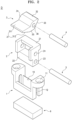
- the vacuum forming product protrusion forming device D comprising: a body portion 1 fixed at one side of the vacuum forming mold; a guide portion 2 inserted in the body portion 1 to be movable in an up and down direction with respect to the body portion 1; a hinge portion 4 connected to one side of the guide portion 2; a protrusion forming portion 3 connected to the one side of the guide portion 2 through the hinge portion 4 to be pivotable within an angular range around the hinge portion 4; and a magnet 6 disposed under the body portion 1 and applying a magnetic force to the protrusion forming portion 3, wherein the body portion 1 comprises: a coupling hole 11 formed to be coupled to the vacuum forming mold; and a storage space 10
- the words "one side of a product” may mean one side or more.
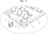
- the protrusion P may be formed at one or more positions of products A and B, and to this end, one or more vacuum forming product protrusion forming devices D with a magnet may be disposed at many positions of a mold.
- the protrusion P protruding in the direction perpendicular to the mold transfer direction may mean a portion of a product having a shape that is not taken out due to interference with a mold in the existing vacuum forming method, when an upper mold and a lower mold are transferred in the vertical direction to be separated from a vacuum mold.
- the protrusion P in the shape illustrated in FIG. 6 is formed by a mold itself, the product and the mold may not be normally separated from each other.
- the vacuum forming product protrusion forming device D with a magnet may be coupled to the mold through a coupling member, such as a screw, a pin, or the like, and the coupling hole 11.
- the certain angle range may be from 75° to 90°.
- the protrusion forming portion 3 maintains the horizontal direction in a process of forming a product, and the protrusion forming portion 3 may pivot to face up in a process of taking out the product.
- the magnet 6 may have a cuboid shape having a size corresponding to an outer peripheral surface of a lower end portion of the body portion 1.
- the guide portion 2 is transferred in a lower direction by a magnetic force of the magnet 6 attracting the protrusion forming portion 3, and thus, a process error due to non-return of the guide portion 2 may be prevented.
- the protrusion forming portion 3 may include a first hinge hole 30 through which the hinge portion 4 passes; a protruding portion 31 extending from the first hinge hole 30 in the horizontal direction by a length, formed to have a width, and having an upper surface formed as a flat plane; a horizontal support surface 32 formed above the first hinge hole 30 to be flat to have a plane parallel to the upper surface of the protruding portion 31; and a vertical support surface 33 formed in a direction opposite to a direction in which the protruding portion 31 is located with respect to the first hinge hole 30 and restricting the angle of the protrusion forming portion 3 during pivoting of the protrusion forming portion 3 from being greater than a predetermined angle.
- the protrusion forming portion 3 may be configured such that, when the vacuum forming mold receives a compressive force, the protruding portion 31 faces the horizontal direction so that a protrusion in the horizontal direction is formed in a product, and when the vacuum forming mold is separated, the protruding portion 31 pivots to be removed from the protrusion formed in the product.
- An adverse slope 312 having an angle may be formed on a bottom surface 312 of the protruding portion 31.
- a horizontal contact surface 35 contacting the guide portion 2 may be formed between the adverse slope 312 and the vertical support surface 33, and connection portions among the adverse slope 312, the horizontal contact surface 35, the vertical support surface 33 may each have a curvature.
- Reference number 34 in FIG. 2 indicates arc shaped profile or contour.
- a flat surface 311 of the protruding portion 31 (the upper surface of the protruding portion 31) is maintained in the horizontal direction (a direction parallel to the ground) and the horizontal contact surface 35 is fixed in close contact with the guide portion 2.
- the protruding portion 31 pivots upward and is fixed such that the vertical support surface 33 is in close contact with the guide portion 2 or an end portion between the vertical support surface 33 and the horizontal support surface 32 is caught by in the guide portion 2.
- a slope (angle) between the adverse slope 312 and the vertical support surface 33 may be formed such that the adverse slope 312 maintains a right angle to the ground when the vertical support surface 33 is in close contact with the guide portion 2 or the end portion between the vertical support surface 33 and the horizontal support surface 32 is caught by in the guide portion 2.
- the hinge portion 4 is coupled to pass through a second hinge hole 24 formed in the guide portion 2 and the first hinge hole 30 of the protrusion forming portion 3.
- the guide portion 2 may include a horizontal support 21 formed in an upper portion of the guide portion 2 to correspond to the horizontal support surface 32.
- the horizontal support surface 32 closely contacts the horizontal support 21 to restrict a lower limit of a rotation angle of the protruding portion 31, and when the vacuum forming mold is separated, the protruding portion 31 is formed to be caught by the horizontal support 21 to restrict an upper limit of the rotation angle of the protruding portion 31.
- the upper portion of the protrusion forming portion 3 includes one portion formed as the horizontal support surface 32 and the other portion formed to have an arc shaped outline concentrically with the center of the hinge portion 4, during the pivoting of the protrusion forming portion 3, no interference occurs between the horizontal support 21 and the protrusion forming portion 3.
- the protruding portion 31 When the horizontal support 21 is not provided, in a vacuum forming process, the protruding portion 31 is bent upward or downward by a compressive force or the like so that protrusions of produced products may be out of tolerance. Furthermore, there may be a case in which the protruding portion 31 is not returned to the original state (a horizontal state) even after, in a product taking-out process, the protruding portion 31 pivots by 90° or more so that a product is taken out product. To address such an issue, as described above, the upper limit and lower limit of the rotation angle of the protrusion forming portion 3 may be physically restricted through the horizontal support 21.
- the guide portion 2 may include a guide body 22 formed in a shape to extrude a figure in a direction perpendicular to fixed surface (bottom surface); a guide fixing hole 23 formed to penetrate one side of the guide body 22; and a guide fixing shaft 5 coupled to the guide fixing hole 23 to constrain the guide portion 2 not to deviate from the body portion 1.
- the body portion 1, where the storage space 10 is formed in a shape corresponding to the guide body 22, may include a guide rail 12 in which the guide fixing shaft 5 is placed and providing a path along which the guide fixing shaft 5 moves according to the vertical movements of the guide portion 2.
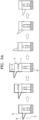
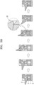
- a process of the operation of the vacuum forming product protrusion forming device with a magnet according to one or more embodiments is described below with reference to FIGS. 5A and 5B .
- a protrusion in detail, an adverse slope protrusion, may be formed on a product formed along the outer peripheral surface of the vacuum forming product protrusion forming device with a magnet by the vacuum forming process.
- the product and the protrusion forming portion 3 and the guide portion 2 connected to the protrusion of the product are transferred upward by power for separating the mold.
- the guide portion 2 may be transferred along the guide rail 12 upward in the vertical direction, and as the guide fixing shaft 5 is caught by an upper end of the guide rail 12, the transfer is stopped.
- a tension load is applied between the protrusion forming portion 3 and the product, by the body portion 1 of the vacuum forming product protrusion forming device with a magnet, which is fixed on the lower mold, and the protrusion forming portion 3 pivots by the tension load so that the protruding portion 31 is removed from the protrusion.
- the vacuum forming product protrusion forming device with a magnet and the product are separated from each other, and thus, the guide portion 2 and the protrusion forming portion 3 are transferred downward by their own weight.
- a method of manufacturing a vacuum forming mold including the vacuum forming product protrusion forming device with a magnet as described above, may include: coupling the protrusion forming portion 3 to the guide portion 2 via the hinge portion 4; inserting the guide portion 2 into the body portion 1; coupling the guide fixing shaft 5 to the guide portion 2; manufacturing the vacuum forming product protrusion forming device D with a magnet by placing the magnet 6 under the body portion 1; and coupling the vacuum forming product protrusion forming device D with a magnet to one side of the vacuum forming mold.
- the protrusion forming portion 3, the hinge portion 4, the body portion 1, the guide portion 2, and the like may include a metal material.
- As the processing of each of the protrusion forming portion 3, the hinge portion 4, the body portion 1, and the guide portion 2 into the shapes as illustrated can be performed by a person skilled in the art with reference to the descriptions of one or more embodiments, detailed descriptions thereof are omitted.
- a vacuum forming method of manufacturing a product by using a vacuum forming mold may include: placing fabric on the vacuum forming mold; forming the fabric by vacuum pressing the same; separating a formed product from the vacuum forming mold; and producing a plurality of products by repeating the placing of the fabric to the separating of the product from the vacuum forming mold.
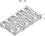
- Protrusion trays A and B manufactured by the vacuum forming method as above are provided.
- the protrusion trays A and B manufactured by vacuum forming are provided, in which the protrusion trays A and B each include a stack portion S formed to stack a plurality of trays, and the stack portion S is formed such that the cross-sectional area (inner cross-sectional area) of the lower portion S2 is greater than the cross-sectional area of an upper portion S1, and as a lower end S3 of a stack portion of the tray A stacked above is placed on a protrusion P of the tray B stacked below, an inner space I is formed between the trays A and B that are stacked such that components arranged in the tray B are prevented from contacting the tray A stacked above.
- the product A may be easily taken out from the mold, and during stacking, the upper portion S1 of the stack portion of the lower tray B is inserted into and placed in the inside of the lower portion S2 of the stack portion of the tray A stacked above.
- a space is formed between a plurality of trays stacked on each other so that components placed in the tray are not contacted by a tray above, while employing a vacuum forming method that is very economical, not an injection molding method.
- a stack protrusion having an adverse slope shape may be formed on an inner side surface of a storage space of a tray manufactured through vacuum forming.
- a stack protrusion having an adverse slope shape may be formed in the tray.
- a product having a protrusion shape (a product with quality/strength of an equivalent level compared with an injection forming product), which has been formed through injection molding only, may be manufactured.
Landscapes
- Engineering & Computer Science (AREA)
- Mechanical Engineering (AREA)
- Manufacturing & Machinery (AREA)
- Ceramic Engineering (AREA)
- Moulds For Moulding Plastics Or The Like (AREA)
- Blow-Moulding Or Thermoforming Of Plastics Or The Like (AREA)
Claims (3)
- Vakuumformverfahren zum Herstellen eines Produkts durch Verwendung einer Vakuumform-Modellform einschließlich einer Vakuumform-Produktvorsprungsformvorrichtung (D), wobei die Vakuumform-Produktvorsprungsformvorrichtung (D) Folgendes umfasst: einen Körperabschnitt (1), der an einer Seite der Vakuumform-Modellform befestigt ist; einen Führungsabschnitt (2), der in den Körperabschnitt (1) eingeführt ist, um in eine Richtung nach oben und nach unten in Bezug auf den Körperabschnitt (1) bewegbar zu sein; einen Scharnierabschnitt (4), der mit einer Seite des Führungsabschnitts (2) verbunden ist; und einen Vorsprungsformabschnitt (3), der durch den Scharnierabschnitt (4) mit der einen Seite des Führungsabschnitts (2) verbunden ist, um innerhalb von einem Winkelbereich um den Scharnierabschnitt (4) herum schwenkbar zu sein, wobei der Körperabschnitt (1) Folgendes umfasst: ein Kopplungsloch (11), das geformt ist, um mit der Vakuumform-Modellform gekoppelt zu werden; und einen Stauraum (10), der geformt ist, damit ein Abschnitt des Führungsabschnitts (2) darin eingeführt werden kann, und in einem Vorgang des Trennens der Vakuumform-Modellform von dem Produkt schwenkt der Vorsprungsformabschnitt (3) um den Scharnierabschnitt (4) herum, wodurch der Vorsprungsformabschnitt (3) aus dem an dem Produkt geformten Vorsprung (P) entfernt wird, wobei das Vakuumformverfahren Folgendes umfasst:Platzieren von Gewebe auf der Vakuumform-Modellform;Formen des Gewebes durch Vakuumpressen desselben;Trennen eines geformten Produkts von der Vakuumform-Modellform; undFertigen einer Vielzahl von Produkten durch Wiederholung des Platzierens des Gewebes bis hin zum Trennen des Produkts von der Vakuumform-Modellform.
- Vakuumformverfahren nach Anspruch 1, wobei der Vorsprungsformabschnitt (3) Folgendes umfasst:ein erstes Scharnierloch (30), durch das der Scharnierabschnitt (4) läuft;einen vorspringenden Abschnitt (31), der sich von dem ersten Scharnierloch (30) in der horizontalen Richtung einer Länge nach erstreckt, dazu geformt, eine Breite aufzuweisen, und mit einer als eine flache Ebene ausgebildeten oberen Oberfläche;eine horizontale Stützoberfläche (32), die oberhalb des ersten Scharnierlochs (30) geformt ist, um flach zu sein, um eine Ebene aufzuweisen, die parallel zu der oberen Oberfläche des vorspringenden Abschnitts (31) ist; undeine vertikale Stützoberfläche (33), die in einer Richtung gegenüber einer Richtung, in der sich der vorspringende Abschnitt (31) in Bezug auf das erste Scharnierloch (30) befindet, geformt ist und während des Schwenkens des Vorsprungsformabschnitts (3) einen Winkel des Vorsprungsformabschnitts (3) begrenzt, damit er nicht größer als ein vorbestimmter Winkel ist, undwobei, wenn die Vakuumform-Modellform eine Druckkraft empfängt, der vorspringende Abschnitt (31) der horizontalen Richtung zugewandt ist, sodass ein Vorsprung in der horizontalen Richtung in einem Produkt geformt wird, undwenn die Vakuumform-Modellform getrennt wird, der vorspringende Abschnitt (31) schwenkt, um aus dem an dem Produkt geformten Vorsprung (P) entfernt zu werden.
- Vakuumformverfahren nach Anspruch 2, wobei der Führungsabschnitt (2) eine horizontale Stütze (21) umfasst, die in einem oberen Abschnitt des Führungsabschnitts (2) geformt ist, um der horizontalen Stützoberfläche (32) zu entsprechen,wenn die Vakuumform-Modellform eine Druckkraft empfängt, die horizontale Stützoberfläche (32) die horizontale Stütze (21) eng kontaktiert, um eine Untergrenze eines Drehwinkels des vorspringenden Abschnitts (31) zu begrenzen,wenn die Vakuumform-Modellform getrennt wird, der vorspringende Abschnitt (31) geformt wird, um von der horizontalen Stütze (21) aufgehalten zu werden, um eine Obergrenze des Drehwinkels des vorspringenden Abschnitts (31) zu begrenzen,ein oberer Abschnitt des Vorsprungsformabschnitts (3) einen Abschnitt einschließt, der als die horizontale Stützoberfläche (32) geformt ist und der andere Abschnitt geformt ist, um einen bogenförmigen Umriss aufzuweisen, der mit der Mitte des Scharnierabschnitts (4) konzentrisch ist, undwährend des Schwenkens des Vorsprungsformabschnitts (3) keine Beeinträchtigung zwischen der horizontalen Stütze (21) und dem Vorsprungsformabschnitt (3) auftritt.
Applications Claiming Priority (1)
| Application Number | Priority Date | Filing Date | Title |
|---|---|---|---|
| KR1020220086699A KR102517655B1 (ko) | 2022-07-14 | 2022-07-14 | 진공성형으로 제조된 돌기형 트레이 |
Publications (2)
| Publication Number | Publication Date |
|---|---|
| EP4306293A1 EP4306293A1 (de) | 2024-01-17 |
| EP4306293B1 true EP4306293B1 (de) | 2025-01-15 |
Family
ID=85884825
Family Applications (1)
| Application Number | Title | Priority Date | Filing Date |
|---|---|---|---|
| EP23185686.5A Active EP4306293B1 (de) | 2022-07-14 | 2023-07-14 | Durch vakuumformen hergestellte protrusionsschale |
Country Status (6)
| Country | Link |
|---|---|
| US (1) | US20240017872A1 (de) |
| EP (1) | EP4306293B1 (de) |
| KR (1) | KR102517655B1 (de) |
| CN (1) | CN117400517A (de) |
| HU (1) | HUE070537T2 (de) |
| PL (1) | PL4306293T3 (de) |
Families Citing this family (2)
| Publication number | Priority date | Publication date | Assignee | Title |
|---|---|---|---|---|
| KR102566365B1 (ko) * | 2022-12-13 | 2023-08-11 | 주식회사 도우인시스 | 트레이 적층시 높이차가 발생되도록 한 트레이 성형 장치 |
| USD1028566S1 (en) * | 2022-12-20 | 2024-05-28 | Icon Outdoors, Llc | Ammunition tray |
Family Cites Families (13)
| Publication number | Priority date | Publication date | Assignee | Title |
|---|---|---|---|---|
| FR2768360B1 (fr) * | 1997-09-16 | 1999-10-29 | Allibert Ind | Procede de moulage d'une piece avec contre-depouille, moule utilise et piece obtenue |
| KR100432213B1 (ko) * | 2001-04-23 | 2004-05-22 | 삼성전자주식회사 | 냉장고용 캐비닛 내상 금형 장치 |
| KR100994819B1 (ko) * | 2010-08-05 | 2010-11-17 | 에이테크솔루션(주) | 냉장고 내상 진공성형용 금형 장치 |
| KR101306075B1 (ko) * | 2011-05-26 | 2013-09-09 | 홍인표 | 진공 성형용 금형 장치 |
| WO2013047338A1 (ja) * | 2011-09-27 | 2013-04-04 | シャープ株式会社 | 物品包装構造 |
| CN203601677U (zh) * | 2013-12-04 | 2014-05-21 | 上海天马微电子有限公司 | 一种托盘 |
| JP6842747B2 (ja) * | 2016-04-19 | 2021-03-17 | 株式会社テクノクラーツ | アンダーカット処理機構、成形用金型 |
| KR101817783B1 (ko) * | 2017-03-21 | 2018-02-21 | 주식회사 성곡 | 진공성형트레이용 적층스토퍼 성형유닛 |
| KR101817784B1 (ko) * | 2017-09-29 | 2018-01-11 | 주식회사 성곡 | 작동형 적층스토퍼 적용 진공성형 트레이금형 |
| WO2019111302A1 (ja) * | 2017-12-04 | 2019-06-13 | 東京プロト株式会社 | 真空成形用金型及びそれを備えた真空成形装置並びにアンダーカットを有するトレイの真空成形方法 |
| KR102042082B1 (ko) | 2018-09-03 | 2019-11-07 | (주)우주일렉트로닉스 | 적층형 트레이를 갖는 커넥터 장치 |
| KR102162061B1 (ko) * | 2019-04-11 | 2020-10-06 | 주식회사 이에스디웍 | 슬라이드 유닛 및 그를 포함하는 진공 성형용 금형 |
| JP2022023381A (ja) * | 2020-07-27 | 2022-02-08 | サイデック株式会社 | 真空成形用金型 |
-
2022
- 2022-07-14 KR KR1020220086699A patent/KR102517655B1/ko active Active
-
2023
- 2023-07-14 CN CN202310871573.0A patent/CN117400517A/zh active Pending
- 2023-07-14 US US18/352,794 patent/US20240017872A1/en active Pending
- 2023-07-14 PL PL23185686.5T patent/PL4306293T3/pl unknown
- 2023-07-14 EP EP23185686.5A patent/EP4306293B1/de active Active
- 2023-07-14 HU HUE23185686A patent/HUE070537T2/hu unknown
Also Published As
| Publication number | Publication date |
|---|---|
| KR102517655B1 (ko) | 2023-04-05 |
| HUE070537T2 (hu) | 2025-06-28 |
| US20240017872A1 (en) | 2024-01-18 |
| EP4306293A1 (de) | 2024-01-17 |
| CN117400517A (zh) | 2024-01-16 |
| PL4306293T3 (pl) | 2025-06-09 |
Similar Documents
| Publication | Publication Date | Title |
|---|---|---|
| EP4306293B1 (de) | Durch vakuumformen hergestellte protrusionsschale | |
| CA2277069C (en) | Integrated circuit tray with self aligning pocket | |
| TWI500567B (zh) | 基板收納容器 | |
| US12090725B2 (en) | Pressure device, battery module manufacturing device, and manufacturing method | |
| US20050109666A1 (en) | Wafer support attachment for a semi-conductor wafer transport container | |
| US9381653B2 (en) | Robot and substrate handling apparatus including the same | |
| US12451384B2 (en) | Substrate storage container | |
| US20090061294A1 (en) | Battery case and battery pack using the same | |
| JP2003243482A (ja) | 枚葉基板の移載装置並びにそれに用いる収納装置及びハンド並びにこれらの装置によって取り扱われる枚葉基板 | |
| EP4092721A1 (de) | Aufnahme- und transportschale für elektronische bauteile mit kleinen abmessungen und geringem gewicht | |
| CN210140061U (zh) | 托盘 | |
| US20220355968A1 (en) | Tray for loading battery cap | |
| KR102581253B1 (ko) | 마그네트가 구비된 진공성형 제품 돌기 성형장치 | |
| JP2011253960A (ja) | 基板収納容器 | |
| US20240317448A1 (en) | Tray for transferring batteries | |
| EP1734573A1 (de) | Stützbehälter für dünne Scheiben | |
| US10004153B2 (en) | Cassette for curved substrates | |
| KR20240099913A (ko) | 배터리 셀 안착 지그 및 이를 포함하는 배터리 셀 정렬 장치 | |
| CN115367251B (zh) | 用于小尺寸和轻重量电子部件的容纳和运输托盘 | |
| JP5717505B2 (ja) | ウエハ収納容器 | |
| EP3616246B1 (de) | Batteriebehälter | |
| JP2017004688A (ja) | 組付け治具、及び、組付け方法 | |
| JP2005162307A (ja) | 半導体装置用トレイ | |
| JP7750627B2 (ja) | トップオープンタイプの基板容器の保持装置 | |
| CN116495461A (zh) | 电池制造用材料移动装置 |
Legal Events
| Date | Code | Title | Description |
|---|---|---|---|
| PUAI | Public reference made under article 153(3) epc to a published international application that has entered the european phase |
Free format text: ORIGINAL CODE: 0009012 |
|
| STAA | Information on the status of an ep patent application or granted ep patent |
Free format text: STATUS: REQUEST FOR EXAMINATION WAS MADE |
|
| 17P | Request for examination filed |
Effective date: 20230714 |
|
| AK | Designated contracting states |
Kind code of ref document: A1 Designated state(s): AL AT BE BG CH CY CZ DE DK EE ES FI FR GB GR HR HU IE IS IT LI LT LU LV MC ME MK MT NL NO PL PT RO RS SE SI SK SM TR |
|
| GRAP | Despatch of communication of intention to grant a patent |
Free format text: ORIGINAL CODE: EPIDOSNIGR1 |
|
| STAA | Information on the status of an ep patent application or granted ep patent |
Free format text: STATUS: GRANT OF PATENT IS INTENDED |
|
| INTG | Intention to grant announced |
Effective date: 20240808 |
|
| GRAS | Grant fee paid |
Free format text: ORIGINAL CODE: EPIDOSNIGR3 |
|
| GRAA | (expected) grant |
Free format text: ORIGINAL CODE: 0009210 |
|
| STAA | Information on the status of an ep patent application or granted ep patent |
Free format text: STATUS: THE PATENT HAS BEEN GRANTED |
|
| AK | Designated contracting states |
Kind code of ref document: B1 Designated state(s): AL AT BE BG CH CY CZ DE DK EE ES FI FR GB GR HR HU IE IS IT LI LT LU LV MC ME MK MT NL NO PL PT RO RS SE SI SK SM TR |
|
| REG | Reference to a national code |
Ref country code: CH Ref legal event code: EP Ref country code: GB Ref legal event code: FG4D |
|
| REG | Reference to a national code |
Ref country code: DE Ref legal event code: R096 Ref document number: 602023001669 Country of ref document: DE |
|
| REG | Reference to a national code |
Ref country code: IE Ref legal event code: FG4D |
|
| REG | Reference to a national code |
Ref country code: NL Ref legal event code: MP Effective date: 20250115 |
|
| PG25 | Lapsed in a contracting state [announced via postgrant information from national office to epo] |
Ref country code: NL Free format text: LAPSE BECAUSE OF FAILURE TO SUBMIT A TRANSLATION OF THE DESCRIPTION OR TO PAY THE FEE WITHIN THE PRESCRIBED TIME-LIMIT Effective date: 20250115 |
|
| REG | Reference to a national code |
Ref country code: HU Ref legal event code: AG4A Ref document number: E070537 Country of ref document: HU |
|
| PG25 | Lapsed in a contracting state [announced via postgrant information from national office to epo] |
Ref country code: RS Free format text: LAPSE BECAUSE OF FAILURE TO SUBMIT A TRANSLATION OF THE DESCRIPTION OR TO PAY THE FEE WITHIN THE PRESCRIBED TIME-LIMIT Effective date: 20250415 |
|
| PG25 | Lapsed in a contracting state [announced via postgrant information from national office to epo] |
Ref country code: FI Free format text: LAPSE BECAUSE OF FAILURE TO SUBMIT A TRANSLATION OF THE DESCRIPTION OR TO PAY THE FEE WITHIN THE PRESCRIBED TIME-LIMIT Effective date: 20250115 |
|
| PGFP | Annual fee paid to national office [announced via postgrant information from national office to epo] |
Ref country code: PL Payment date: 20250630 Year of fee payment: 3 |
|
| PG25 | Lapsed in a contracting state [announced via postgrant information from national office to epo] |
Ref country code: ES Free format text: LAPSE BECAUSE OF FAILURE TO SUBMIT A TRANSLATION OF THE DESCRIPTION OR TO PAY THE FEE WITHIN THE PRESCRIBED TIME-LIMIT Effective date: 20250115 |
|
| REG | Reference to a national code |
Ref country code: LT Ref legal event code: MG9D |
|
| PG25 | Lapsed in a contracting state [announced via postgrant information from national office to epo] |
Ref country code: IS Free format text: LAPSE BECAUSE OF FAILURE TO SUBMIT A TRANSLATION OF THE DESCRIPTION OR TO PAY THE FEE WITHIN THE PRESCRIBED TIME-LIMIT Effective date: 20250515 Ref country code: NO Free format text: LAPSE BECAUSE OF FAILURE TO SUBMIT A TRANSLATION OF THE DESCRIPTION OR TO PAY THE FEE WITHIN THE PRESCRIBED TIME-LIMIT Effective date: 20250415 |
|
| REG | Reference to a national code |
Ref country code: AT Ref legal event code: MK05 Ref document number: 1759583 Country of ref document: AT Kind code of ref document: T Effective date: 20250115 |
|
| PG25 | Lapsed in a contracting state [announced via postgrant information from national office to epo] |
Ref country code: HR Free format text: LAPSE BECAUSE OF FAILURE TO SUBMIT A TRANSLATION OF THE DESCRIPTION OR TO PAY THE FEE WITHIN THE PRESCRIBED TIME-LIMIT Effective date: 20250115 |
|
| PG25 | Lapsed in a contracting state [announced via postgrant information from national office to epo] |
Ref country code: LV Free format text: LAPSE BECAUSE OF FAILURE TO SUBMIT A TRANSLATION OF THE DESCRIPTION OR TO PAY THE FEE WITHIN THE PRESCRIBED TIME-LIMIT Effective date: 20250115 Ref country code: PT Free format text: LAPSE BECAUSE OF FAILURE TO SUBMIT A TRANSLATION OF THE DESCRIPTION OR TO PAY THE FEE WITHIN THE PRESCRIBED TIME-LIMIT Effective date: 20250515 |
|
| PGFP | Annual fee paid to national office [announced via postgrant information from national office to epo] |
Ref country code: FR Payment date: 20250623 Year of fee payment: 3 |
|
| PG25 | Lapsed in a contracting state [announced via postgrant information from national office to epo] |
Ref country code: GR Free format text: LAPSE BECAUSE OF FAILURE TO SUBMIT A TRANSLATION OF THE DESCRIPTION OR TO PAY THE FEE WITHIN THE PRESCRIBED TIME-LIMIT Effective date: 20250416 Ref country code: BG Free format text: LAPSE BECAUSE OF FAILURE TO SUBMIT A TRANSLATION OF THE DESCRIPTION OR TO PAY THE FEE WITHIN THE PRESCRIBED TIME-LIMIT Effective date: 20250115 |
|
| PG25 | Lapsed in a contracting state [announced via postgrant information from national office to epo] |
Ref country code: AT Free format text: LAPSE BECAUSE OF FAILURE TO SUBMIT A TRANSLATION OF THE DESCRIPTION OR TO PAY THE FEE WITHIN THE PRESCRIBED TIME-LIMIT Effective date: 20250115 |
|
| PGFP | Annual fee paid to national office [announced via postgrant information from national office to epo] |
Ref country code: HU Payment date: 20250711 Year of fee payment: 3 |
|
| PG25 | Lapsed in a contracting state [announced via postgrant information from national office to epo] |
Ref country code: SE Free format text: LAPSE BECAUSE OF FAILURE TO SUBMIT A TRANSLATION OF THE DESCRIPTION OR TO PAY THE FEE WITHIN THE PRESCRIBED TIME-LIMIT Effective date: 20250115 |
|
| PG25 | Lapsed in a contracting state [announced via postgrant information from national office to epo] |
Ref country code: SM Free format text: LAPSE BECAUSE OF FAILURE TO SUBMIT A TRANSLATION OF THE DESCRIPTION OR TO PAY THE FEE WITHIN THE PRESCRIBED TIME-LIMIT Effective date: 20250115 |
|
| PG25 | Lapsed in a contracting state [announced via postgrant information from national office to epo] |
Ref country code: DK Free format text: LAPSE BECAUSE OF FAILURE TO SUBMIT A TRANSLATION OF THE DESCRIPTION OR TO PAY THE FEE WITHIN THE PRESCRIBED TIME-LIMIT Effective date: 20250115 |
|
| PGFP | Annual fee paid to national office [announced via postgrant information from national office to epo] |
Ref country code: DE Payment date: 20250624 Year of fee payment: 3 |
|
| PG25 | Lapsed in a contracting state [announced via postgrant information from national office to epo] |
Ref country code: IT Free format text: LAPSE BECAUSE OF FAILURE TO SUBMIT A TRANSLATION OF THE DESCRIPTION OR TO PAY THE FEE WITHIN THE PRESCRIBED TIME-LIMIT Effective date: 20250115 |
|
| REG | Reference to a national code |
Ref country code: DE Ref legal event code: R097 Ref document number: 602023001669 Country of ref document: DE |
|
| PG25 | Lapsed in a contracting state [announced via postgrant information from national office to epo] |
Ref country code: EE Free format text: LAPSE BECAUSE OF FAILURE TO SUBMIT A TRANSLATION OF THE DESCRIPTION OR TO PAY THE FEE WITHIN THE PRESCRIBED TIME-LIMIT Effective date: 20250115 Ref country code: CZ Free format text: LAPSE BECAUSE OF FAILURE TO SUBMIT A TRANSLATION OF THE DESCRIPTION OR TO PAY THE FEE WITHIN THE PRESCRIBED TIME-LIMIT Effective date: 20250115 |
|
| PG25 | Lapsed in a contracting state [announced via postgrant information from national office to epo] |
Ref country code: RO Free format text: LAPSE BECAUSE OF FAILURE TO SUBMIT A TRANSLATION OF THE DESCRIPTION OR TO PAY THE FEE WITHIN THE PRESCRIBED TIME-LIMIT Effective date: 20250115 |
|
| PG25 | Lapsed in a contracting state [announced via postgrant information from national office to epo] |
Ref country code: SK Free format text: LAPSE BECAUSE OF FAILURE TO SUBMIT A TRANSLATION OF THE DESCRIPTION OR TO PAY THE FEE WITHIN THE PRESCRIBED TIME-LIMIT Effective date: 20250115 |
|
| PLBE | No opposition filed within time limit |
Free format text: ORIGINAL CODE: 0009261 |
|
| STAA | Information on the status of an ep patent application or granted ep patent |
Free format text: STATUS: NO OPPOSITION FILED WITHIN TIME LIMIT |
|
| 26N | No opposition filed |
Effective date: 20251016 |
|
| PG25 | Lapsed in a contracting state [announced via postgrant information from national office to epo] |
Ref country code: LU Free format text: LAPSE BECAUSE OF NON-PAYMENT OF DUE FEES Effective date: 20250714 |
|
| REG | Reference to a national code |
Ref country code: BE Ref legal event code: MM Effective date: 20250731 |
|
| PG25 | Lapsed in a contracting state [announced via postgrant information from national office to epo] |
Ref country code: BE Free format text: LAPSE BECAUSE OF NON-PAYMENT OF DUE FEES Effective date: 20250731 |