EP4305245B1 - Abdeckung einer bauteilöffnung eines bauteils als pfahl insbesondere eines offshore-bauwerks - Google Patents
Abdeckung einer bauteilöffnung eines bauteils als pfahl insbesondere eines offshore-bauwerks Download PDFInfo
- Publication number
- EP4305245B1 EP4305245B1 EP22712377.5A EP22712377A EP4305245B1 EP 4305245 B1 EP4305245 B1 EP 4305245B1 EP 22712377 A EP22712377 A EP 22712377A EP 4305245 B1 EP4305245 B1 EP 4305245B1
- Authority
- EP
- European Patent Office
- Prior art keywords
- component
- pile
- cover
- opening
- fan
- Prior art date
- Legal status (The legal status is an assumption and is not a legal conclusion. Google has not performed a legal analysis and makes no representation as to the accuracy of the status listed.)
- Active
Links
Images


Classifications
-
- E—FIXED CONSTRUCTIONS
- E02—HYDRAULIC ENGINEERING; FOUNDATIONS; SOIL SHIFTING
- E02D—FOUNDATIONS; EXCAVATIONS; EMBANKMENTS; UNDERGROUND OR UNDERWATER STRUCTURES
- E02D5/00—Bulkheads, piles, or other structural elements specially adapted to foundation engineering
- E02D5/22—Piles
- E02D5/226—Protecting piles
-
- E—FIXED CONSTRUCTIONS
- E02—HYDRAULIC ENGINEERING; FOUNDATIONS; SOIL SHIFTING
- E02B—HYDRAULIC ENGINEERING
- E02B17/00—Artificial islands mounted on piles or like supports, e.g. platforms on raisable legs or offshore constructions; Construction methods therefor
- E02B17/02—Artificial islands mounted on piles or like supports, e.g. platforms on raisable legs or offshore constructions; Construction methods therefor placed by lowering the supporting construction to the bottom, e.g. with subsequent fixing thereto
-
- E—FIXED CONSTRUCTIONS
- E02—HYDRAULIC ENGINEERING; FOUNDATIONS; SOIL SHIFTING
- E02D—FOUNDATIONS; EXCAVATIONS; EMBANKMENTS; UNDERGROUND OR UNDERWATER STRUCTURES
- E02D15/00—Handling building or like materials for hydraulic engineering or foundations
- E02D15/08—Sinking workpieces into water or soil inasmuch as not provided for elsewhere
-
- E—FIXED CONSTRUCTIONS
- E02—HYDRAULIC ENGINEERING; FOUNDATIONS; SOIL SHIFTING
- E02D—FOUNDATIONS; EXCAVATIONS; EMBANKMENTS; UNDERGROUND OR UNDERWATER STRUCTURES
- E02D27/00—Foundations as substructures
- E02D27/32—Foundations for special purposes
- E02D27/50—Anchored foundations
-
- E—FIXED CONSTRUCTIONS
- E02—HYDRAULIC ENGINEERING; FOUNDATIONS; SOIL SHIFTING
- E02D—FOUNDATIONS; EXCAVATIONS; EMBANKMENTS; UNDERGROUND OR UNDERWATER STRUCTURES
- E02D27/00—Foundations as substructures
- E02D27/32—Foundations for special purposes
- E02D27/52—Submerged foundations, i.e. submerged in open water
- E02D27/525—Submerged foundations, i.e. submerged in open water using elements penetrating the underwater ground
-
- E—FIXED CONSTRUCTIONS
- E02—HYDRAULIC ENGINEERING; FOUNDATIONS; SOIL SHIFTING
- E02D—FOUNDATIONS; EXCAVATIONS; EMBANKMENTS; UNDERGROUND OR UNDERWATER STRUCTURES
- E02D31/00—Protective arrangements for foundations or foundation structures; Ground foundation measures for protecting the soil or the subsoil water, e.g. preventing or counteracting oil pollution
-
- E—FIXED CONSTRUCTIONS
- E02—HYDRAULIC ENGINEERING; FOUNDATIONS; SOIL SHIFTING
- E02D—FOUNDATIONS; EXCAVATIONS; EMBANKMENTS; UNDERGROUND OR UNDERWATER STRUCTURES
- E02D5/00—Bulkheads, piles, or other structural elements specially adapted to foundation engineering
- E02D5/22—Piles
- E02D5/223—Details of top sections of foundation piles
-
- E—FIXED CONSTRUCTIONS
- E04—BUILDING
- E04H—BUILDINGS OR LIKE STRUCTURES FOR PARTICULAR PURPOSES; SWIMMING OR SPLASH BATHS OR POOLS; MASTS; FENCING; TENTS OR CANOPIES, IN GENERAL
- E04H7/00—Construction or assembling of bulk storage containers employing civil engineering techniques in situ or off the site
- E04H7/22—Containers for fluent solids, e.g. silos, bunkers; Supports therefor
-
- F—MECHANICAL ENGINEERING; LIGHTING; HEATING; WEAPONS; BLASTING
- F24—HEATING; RANGES; VENTILATING
- F24F—AIR-CONDITIONING; AIR-HUMIDIFICATION; VENTILATION; USE OF AIR CURRENTS FOR SCREENING
- F24F13/00—Details common to, or for air-conditioning, air-humidification, ventilation or use of air currents for screening
- F24F13/20—Casings or covers
-
- F—MECHANICAL ENGINEERING; LIGHTING; HEATING; WEAPONS; BLASTING
- F24—HEATING; RANGES; VENTILATING
- F24F—AIR-CONDITIONING; AIR-HUMIDIFICATION; VENTILATION; USE OF AIR CURRENTS FOR SCREENING
- F24F7/00—Ventilation
- F24F7/02—Roof ventilation
- F24F7/025—Roof ventilation with forced air circulation by means of a built-in ventilator
-
- E—FIXED CONSTRUCTIONS
- E02—HYDRAULIC ENGINEERING; FOUNDATIONS; SOIL SHIFTING
- E02B—HYDRAULIC ENGINEERING
- E02B17/00—Artificial islands mounted on piles or like supports, e.g. platforms on raisable legs or offshore constructions; Construction methods therefor
- E02B2017/0039—Methods for placing the offshore structure
- E02B2017/0043—Placing the offshore structure on a pre-installed foundation structure
-
- E—FIXED CONSTRUCTIONS
- E02—HYDRAULIC ENGINEERING; FOUNDATIONS; SOIL SHIFTING
- E02B—HYDRAULIC ENGINEERING
- E02B17/00—Artificial islands mounted on piles or like supports, e.g. platforms on raisable legs or offshore constructions; Construction methods therefor
- E02B2017/0091—Offshore structures for wind turbines
-
- E—FIXED CONSTRUCTIONS
- E02—HYDRAULIC ENGINEERING; FOUNDATIONS; SOIL SHIFTING
- E02D—FOUNDATIONS; EXCAVATIONS; EMBANKMENTS; UNDERGROUND OR UNDERWATER STRUCTURES
- E02D27/00—Foundations as substructures
- E02D27/32—Foundations for special purposes
- E02D27/42—Foundations for poles, masts or chimneys
- E02D27/425—Foundations for poles, masts or chimneys specially adapted for wind motors masts
-
- F—MECHANICAL ENGINEERING; LIGHTING; HEATING; WEAPONS; BLASTING
- F24—HEATING; RANGES; VENTILATING
- F24F—AIR-CONDITIONING; AIR-HUMIDIFICATION; VENTILATION; USE OF AIR CURRENTS FOR SCREENING
- F24F13/00—Details common to, or for air-conditioning, air-humidification, ventilation or use of air currents for screening
- F24F13/20—Casings or covers
- F24F2013/205—Mounting a ventilator fan therein
-
- Y—GENERAL TAGGING OF NEW TECHNOLOGICAL DEVELOPMENTS; GENERAL TAGGING OF CROSS-SECTIONAL TECHNOLOGIES SPANNING OVER SEVERAL SECTIONS OF THE IPC; TECHNICAL SUBJECTS COVERED BY FORMER USPC CROSS-REFERENCE ART COLLECTIONS [XRACs] AND DIGESTS
- Y02—TECHNOLOGIES OR APPLICATIONS FOR MITIGATION OR ADAPTATION AGAINST CLIMATE CHANGE
- Y02E—REDUCTION OF GREENHOUSE GAS [GHG] EMISSIONS, RELATED TO ENERGY GENERATION, TRANSMISSION OR DISTRIBUTION
- Y02E10/00—Energy generation through renewable energy sources
- Y02E10/70—Wind energy
- Y02E10/72—Wind turbines with rotation axis in wind direction
-
- Y—GENERAL TAGGING OF NEW TECHNOLOGICAL DEVELOPMENTS; GENERAL TAGGING OF CROSS-SECTIONAL TECHNOLOGIES SPANNING OVER SEVERAL SECTIONS OF THE IPC; TECHNICAL SUBJECTS COVERED BY FORMER USPC CROSS-REFERENCE ART COLLECTIONS [XRACs] AND DIGESTS
- Y02—TECHNOLOGIES OR APPLICATIONS FOR MITIGATION OR ADAPTATION AGAINST CLIMATE CHANGE
- Y02E—REDUCTION OF GREENHOUSE GAS [GHG] EMISSIONS, RELATED TO ENERGY GENERATION, TRANSMISSION OR DISTRIBUTION
- Y02E10/00—Energy generation through renewable energy sources
- Y02E10/70—Wind energy
- Y02E10/727—Offshore wind turbines
Definitions
- the invention relates to a method for assembling an offshore structure, in particular an offshore wind turbine.
- the invention also relates to an arrangement which has a hollow component as a pile with a component opening, in particular a pile that is open at the top.
- the component opening is closed with a cover in order to protect the component from external influences between assembly steps.
- Offshore wind turbines usually have a hollow pile as a foundation structure.
- the WO 2020/074 421 A1 describes a wind turbine with a hollow structural element.
- To assemble an offshore wind turbine the pile is first anchored in the seabed. A tower structure is then erected on the pile. In practice, several months can pass between these two steps. It is therefore common practice to close the pile, which is open at the top, with a cover until the tower structure is erected. This protects the interior of the pile from external influences. Immediately before the tower structure is erected, the cover is removed.
- covers Simple tarpaulins that are attached to the post with tensioning straps are known as covers for the purpose described.
- covers are often difficult to install, especially in strong winds.
- these covers completely enclose the post. This can cause mold to form inside the post.
- access to the inside of the post is made more difficult by the known covers, for example for assembly work inside.
- the so-called cable pull-in is made more difficult by such a cover.
- the EP 1 607 348 A1 relates to a cover for a tank, which comprises a container wall, a roof and, if appropriate, vent nozzles, pump pipes, pressure gauges, railing bars or the like protruding from the roof.
- the FR 2 695 157 A1 concerns the covering of pits with tarpaulins.
- the CN 204 498 825 U describes a hollow component with a component opening and a cover for it.
- Components with a cavity are known in various contexts. From the GB 748,179 A For example, a silo for cement is known. WO 2021/014 052 A1 A hollow pile is known. The object of the present invention is, based on the described prior art, to provide a cover for the component opening of a hollow component as a pile, with which mold formation is prevented and accessibility is facilitated.
- the arrangement can be an intermediate product from which a structure can be obtained.
- the cover can temporarily close a component opening in the component.
- the cover can be removed if the component opening in the component is otherwise and permanently closed, for example by attaching an attachment to the component.
- the cover can therefore be used to close a component opening in the component during a construction process and thus protect the interior from external influences. This is particularly advantageous if an electrical device is installed in the interior.
- the structure can in particular be an offshore wind turbine.
- the cover can serve to protect a pile anchored in the seabed and open at the top as the component from external influences until the tower structure is mounted on the pile. Once the tower structure is mounted, the component opening on the top of the pile is permanently closed by the tower structure, so that the cover is no longer required.
- the cover can be intended for single use. In this case, the cover is disposed of when the tower structure is mounted. However, it is also conceivable that the cover is reused in whole or in part. Alternatively, the cover can also be used in an intermediate product for any other structure to temporarily close a component opening during a construction process.
- the arrangement can also be a completed building.
- the cover can permanently or temporarily close a component opening.
- a lateral component opening in any building is permanently or temporarily closed by the cover.
- the arrangement comprises a hollow component as a pile.
- the hollow component preferably has a round cross-section, in particular a circular cross-section.
- the component can in particular be tubular.
- the component is preferably cylindrical.
- the component preferably has a circumferential casing wall.
- the component is preferably open on both of its end faces.
- the component opening closed by the cover is in this case formed by one of the two open end faces.
- the component opening preferably extends over the entire end face of the component. It is also conceivable that the component opening is arranged on the side of the component, in particular in a casing wall.
- a component opening is an opening in the component.
- the term component opening is used solely to distinguish it from other openings described herein, in particular from the ventilation opening.
- the component opening preferably has a cross-sectional area in the range of 1 to 100 m 2 , in particular in the range of 10 to 50 m 2 .
- the component opening preferably has a circular cross-section, in particular with a diameter in the range of 1 to 10 m.
- the arrangement also has a cover that closes the component opening.
- External influences include weather influences such as rain and snow. Bird droppings are also a possibility.
- the ingress of of sea water in high waves In the case of an offshore wind turbine, the ingress of of sea water in high waves.
- the arrangement has a fan which is attached to the cover.
- the fan preferably guides air from an area surrounding the arrangement through the ventilation opening in the cover into the interior of the component. It is also conceivable for the fan to guide air from the interior of the component through the ventilation opening in the cover into the area surrounding the arrangement.
- the following example looks at the case where air is introduced into the interior of the component using the fan. The same applies to the opposite case.
- the ventilation opening preferably has a diameter in the range of 20 to 200 cm.
- the cover preferably has one or more pressure equalization openings. Air can escape from the interior of the component through these when air is transported into the interior of the component by the fan.
- the pressure equalization openings are preferably arranged in such a way that no water can enter the interior of the component from the outside through them.
- a cross-section of the ventilation openings is preferably less than 10% of the surface of the cover.
- the air can be introduced directly into the entire interior of the component using the fan.
- a ventilation hose can be connected to the ventilation opening on the inside of the cover. The air can be guided to a desired location within the interior of the component via the ventilation hose.
- the ventilation hose preferably has a plastic casing wall with an integrated wire spiral that gives the casing wall its shape.
- the fan is pivotably mounted on the cover. This is possible, for example, by holding the fan to the cover via one or more hinges.
- the fan can pivot between a first position and a second position. In the first position, the fan covers the ventilation opening in the cover so that the fan can transport air through the ventilation opening. This is the operating position in which the fan can be used to ventilate the interior of the component. In the second position, the fan is pivoted away from the ventilation opening. The ventilation opening is therefore exposed.
- the ventilation opening can therefore be used as access to the interior of the component.
- the arrangement described enables particularly easy access to the interior of the component. In particular, no separate access opening in the cover is required for this. Nevertheless, the cover can also have one or more access openings in addition to the ventilation opening.
- the pivotability of the fan nevertheless makes access to the interior of the component easier because without the pivotability of the fan, access would not be possible at the location of the ventilation opening. If a ventilation hose is connected to the ventilation opening, this can be removed when the fan is pivoted from the operating position to the second position. This means that the interior of the post can be accessed via the ventilation opening despite the ventilation hose.
- the arrangement preferably has a staircase.
- the staircase is preferably arranged outside the cover and preferably extends between the edge of the component opening and the fan.
- the ventilation opening can be used via the staircase as access to the interior of the component when the fan is pivoted away.
- the component is a foundation structure anchored in a seabed for an offshore structure.
- the component serves as the foundation of an offshore structure, in particular an offshore wind turbine.
- the component is anchored in the seabed on the one hand.
- the component preferably protrudes from the water at normal water levels. The latter does not exclude the possibility that the water can completely enclose the component, for example in high waves.
- the offshore structure preferably comprises other elements and in particular a component structure.
- a tower structure is such a component structure.
- the tower structure can be attached directly to the component or via an intermediate element, in particular via a so-called transition piece.
- the cover preferably serves to temporarily close the component opening of the component.
- the cover can thus serve to protect the interior of the component anchored in the seabed until the tower structure is assembled.
- the arrangement represents an intermediate product from which an offshore structure such as an offshore wind turbine can be obtained.
- the cover is part of the arrangement, but not part of the completed offshore structure.
- the component is a pile, wherein the component opening is arranged on a front side of the pile.
- the pile preferably has a closed outer surface.
- the pile is preferably open on both ends.
- the component opening is formed on one of the two ends and is closed by the cover.
- the component opening preferably extends over the entire cross-section of the pile.
- the component opening can also be referred to here as a pile opening.
- An opening in the pile is referred to as a pile opening.
- pile opening is used solely to linguistically differentiate it from other openings described here, in particular from the ventilation opening.
- the pile can be designed as a foundation structure for an offshore structure, in particular for an offshore wind turbine.
- the pile can also be referred to as a monopile.
- the pile can be driven into the seabed, for example by ramming or vibrating. Since the pile is open at the bottom, material from the seabed can get into the pile. The pile can thus be filled with material to such an extent that the seabed inside and outside the pile is at the same level. In this case, the interior of the pile to be ventilated extends from the seabed to the component opening closed with the cover.
- the fan is arranged in an operating position on an axis of the component opening.
- the fan in this embodiment is arranged centrally in relation to the cross-section of the component opening.
- the axis of the component opening preferably coincides with an axis of the pile. In this case, the axis of the pile also runs through the fan when it is in the operating position.
- the ventilation opening can be opened up and used to access the interior of the component.
- the central arrangement of the fan and consequently the central arrangement of the ventilation opening facilitate accessibility to the interior. From a centrally arranged ventilation opening, all points of the interior can be reached relatively easily.
- An axis of the ventilation opening preferably coincides with the axis of the component opening to be closed.
- the cover has an annular plate on which the fan is held.
- the ring plate is ring-shaped in that the ventilation opening is formed in the middle of the ring plate.
- the fan can be held to the ring plate, for example, via one or more hinges.
- the ring plate can also contribute to the stability of the cover.
- the ring plate preferably has an outer diameter in the range of 50 to 300 cm and an inner diameter in the range of 20 to 200 cm, whereby the inner diameter is always smaller than the outer diameter.
- the cover has a rod covered with a tarpaulin.
- the rod preferably has a plurality of rods.
- rods can be arranged like spokes and each extend from the edge of the ventilation opening extend to the edge of the component opening.
- the rods are preferably attached to the edge of the component opening and/or to the edge of the ventilation opening with a plug connection.
- the plug connections are preferably secured with a respective split pin.
- each end of the rods can be inserted through a corresponding hole on the edge of the component opening and secured with a respective split pin.
- the plug connections allow the cover to be easily assembled and disassembled.
- the edge of the ventilation opening can in particular be formed by the ring plate. In this respect, the ring plate can serve to hold the rods.
- the rods are covered with a tarpaulin.
- the tarpaulin protects the interior of the component.
- the design of the cover with tarpaulin and rods makes the cover particularly light and correspondingly easy to transport, assemble and disassemble.
- the cover preferably has a mass in the range of 100 to 300 kg.
- the pile of the offshore structure represents a component in the sense of the arrangement described.
- an arrangement designed as described is preferably present. The described advantages and features of the arrangement are applicable and transferable to the method, and vice versa.
- the method is used to assemble an offshore structure.
- the offshore structure is preferably an offshore wind turbine.
- the method is used to assemble other offshore structures that have one or more piles anchored in the seabed as a foundation structure.
- such an offshore structure can be an offshore platform In the case of several piles, steps a) and b) are carried out accordingly.
- step a) a pile is anchored in the seabed.
- the component opening is closed by a cover.
- the pile can first be anchored in the seabed and the cover can then be attached.
- step a) involves closing the component opening with a cover. Closing the opening is therefore part of step a) and, to that extent, part of the process.
- the pile can be anchored in the seabed with a pre-assembled cover.
- a pile is used for step a) in which the component opening is closed by a cover.
- the cover can, for example, be mounted on the pile in a harbor and the pile with the cover can then be transported to its destination.
- step a) involves attaching the fan to the cover. Attaching the fan is therefore part of step a) and therefore part of the procedure. This is possible both when the cover is attached to the pile after the pile has been anchored to the seabed and when a pile with a pre-assembled cover without a fan is used. Alternatively, a cover with a pre-assembled fan can be used. In this case, step a) is carried out with a cover to which the fan is pivotally attached. The pre-assembled cover can be attached to the pile after it has been anchored to the seabed. Alternatively, a pile can be used on which a pre-assembled cover with a fan is already pre-assembled.
- step a the interior of the pile is protected by the cover.
- the pile can remain in this state until the building structure is attached to it.
- the cover is removed in step b), for example using a crane.
- the waiting time is preferably at least one day, especially at least one month.
- the post can overwinter with the cover.
- the building structure is mounted on the pile.
- the building structure is preferably a tower structure, in particular in the case of an offshore wind turbine.
- the tower structure can comprise a tower, a nacelle with a generator and rotor blades connected to it.
- the tower can be mounted directly on the pile.
- the tower can be connected to the pile via an intermediate element, in particular a so-called transition piece.
- the cover is cut up in step b) and then disposed of.
- Cutting the cover can, for example, involve cutting the cover's tarpaulin at several points.
- the tarpaulin can be cut into segments that each extend between two adjacent rods of the rod system.
- cutting the cover can involve dismantling a rod system of the cover.
- the surface area of the cover can be reduced so that the cover offers less surface area for wind to attack. This makes it easier to remove the cover.
- the parts of the cover can be collected in a big bag and transported away.
- the cover is not reused but disposed of. This makes it easier to cut up the cover, as the cover can be destroyed in the process. It also makes sense to only use the cover once.
- the cover can be damaged during use, for example if the wind deforms the rods. Detecting and repairing such damage can be complex.
- a winch device is mounted outside the cover on an edge of the component opening of the pile and the fan is moved from an operating position swung away so that the interior of the pole is accessible via the ventilation opening in the cover for the winch device.
- a winch device is understood to be a device that, in addition to a winch, also has fastening means by which the winch can be attached to the pile.
- the winch device is mounted on the edge of the component opening of the pile, i.e. on the front side of the pile, which is above the water line.
- the winch device is arranged outside of the water at normal water levels.
- the fastening means preferably comprise a frame with three or more legs, which are attached to the edge of the component opening.
- the winch device can be used to move loads inside the pile, especially up or down. With the help of the winch device, a medium-voltage circuit can be installed inside the pile, for example.
- the winch device is preferably dismantled again before step b).
- the winch device is used for cable pull-in between steps a) and b).
- the electricity generated by an offshore wind turbine can be supplied via a cable laid on the seabed.
- This cable is connected when the offshore wind turbine is assembled.
- the cable can be fed through a hole in the casing wall of the pile below the waterline.
- the cable can then be pulled up inside the pile and connected.
- This process is called cable pull-in.
- the winch device is used for this.
- the advantages of cable pull-in described above can be achieved.
- the central arrangement of the ventilation opening means that the cable can be pulled up and connected centrally in the pile. This is advantageous because the cable can be kept away from the casing wall of the pile.
- Fig. 1 illustrates a method for assembling an offshore wind turbine as an offshore structure 7.
- Fig. 1a illustrates a step a) in which a hollow pile 8 is anchored in a seabed 13 so that a (in Fig. 1b shown) component opening 3 is located on a front side 9 of the pile 8 above a water line 14.
- the pile 8 is a component 2.
- the component opening 3 is closed by a cover 4, whereby a fan 5 for ventilating an interior 6 of the pile 8 is pivotally attached to the cover 4.
- the interior 6 of the pile 8 is protected by the cover 4.
- the Fig. 1a The arrangement 1 comprises the post 8, the cover 4 and the fan 5.
- Fig. 1b illustrates a step b) in which the cover 4 is removed.
- the cover 4 can be cut into pieces and then disposed of.
- Fig. 1c illustrates a step c) in which a tower structure is mounted as a building structure 15 on the pile 8. This turns the arrangement 1 into an offshore structure 7.
- the previously existing component opening 3 is permanently closed by the tower structure.
- the pile 8 is a foundation structure anchored in the seabed 13 for the offshore structure 7.
- Fig. 2a shows an enlargement of a part of Fig. 1a .
- the pile 8 is shown as the component 2 with the front side 9, which is arranged above the waterline 14.
- the pile 8 has the (in Fig. 1b and 2b shown) component opening 3, which is closed by the cover 4.
- the cover 4 has a rod 12 covered with a tarpaulin 11.
- the fan 5 is arranged on an axis A of the component opening 3.
- the axis A is also an axis of the component 2.
- the cover 4 has a ring plate 10.
- a ventilation opening 17 is formed centrally in the ring plate 10.
- the interior 6 of the post 8 can be ventilated with the fan 5 via the ventilation opening 17 in the cover 4. This is shown in the Fig. 2a shown operating position of the fan 5 is possible.
- Fig. 2b shows a top view of the Fig. 2a Shown.
- the cover 4 with the tarpaulin 11 and the rod 12 can be seen.
- only one tarpaulin segment is provided with reference number 11 and one rod with reference number 12.
- the ventilation opening 17 is formed centrally in the ring plate 10.
- the component opening 3 is also shown. This extends over the entire front side 9 of the post 8, i.e. in Fig. 2b over the entire circle marked with reference number 3.
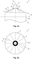
- Fig. 3a is the arrangement 1 from Fig. 2a shown in another state. In this state, the fan 5 is out of the Fig. 2a and 2b shown operating position.
- a winch device 16 is mounted outside the cover 4 on an edge of the component opening 3 of the pile 8. For the sake of clarity, the axis A of the component opening is not shown here.
- the interior 6 of the pile 8 is accessible to the winch device 16 via the ventilation opening 17 in the cover 4.
- This is indicated insofar as a cable 18 of the winch device 16 is shown, which is guided through the ventilation opening 17 into the interior 6 of the pile 8.
- the cable 18 is attached to a winch of the winch device 16 (not shown).
- a hook 19 is indicated, via which loads can be picked up.
- the winch device 16 can be used in particular between steps a) and b) for cable pull-in.
- Fig. 3b shows a top view of the Fig. 2a shown.
- the cover 4 can be used to close the component opening 3 of the component 2, so that the interior 6 of the component 2 is protected from external influences.
- the fan 5 can be used to prevent the formation of mold in the interior 6 of the component 2. Because the fan 5 is pivotably attached to the cover 4, the interior 6 of the component 2 is particularly easy to access.
Landscapes
- Engineering & Computer Science (AREA)
- Structural Engineering (AREA)
- General Engineering & Computer Science (AREA)
- Life Sciences & Earth Sciences (AREA)
- Civil Engineering (AREA)
- General Life Sciences & Earth Sciences (AREA)
- Mining & Mineral Resources (AREA)
- Paleontology (AREA)
- Architecture (AREA)
- Mechanical Engineering (AREA)
- Combustion & Propulsion (AREA)
- Chemical & Material Sciences (AREA)
- Environmental & Geological Engineering (AREA)
- Hydrology & Water Resources (AREA)
- Wind Motors (AREA)
- Foundations (AREA)
Description
- Die Erfindung betrifft ein Verfahren zur Montage eines Offshore-Bauwerks, insbesondere einer Offshore-Windenergieanlage. Zudem betrifft die Erfindung eine Anordnung, welche ein hohles Bauteil als Pfahl mit einer Bauteilöffnung aufweist, insbesondere einen oben offenen Pfahl. Die Bauteilöffnung ist mit einer Abdeckung verschlossen, um das Bauteil zwischen Montageschritten vor äußeren Einflüssen zu schützen.
- Offshore-Windenergieanlagen weisen üblicherweise einen hohlen Pfahl als Gründungsstruktur auf. Beispielsweise die
WO 2020/074 421 A1 beschreibt eine Windkraftanlage mit einem Hohlstrukturelement. Zur Montage einer Offshore-Windenergieanlage wird der Pfahl zunächst im Meeresgrund verankert. Anschließend wird eine Turmstruktur auf dem Pfahl errichtet. Zwischen diesen beiden Schritten können in der Praxis mehrere Monate vergehen. Daher ist es üblich, den nach oben offenen Pfahl mit einer Abdeckung zu verschließen, bis die Turmstruktur errichtet wird. So wird der Innenraum des Pfahls vor äußeren Einflüssen geschützt. Unmittelbar bevor die Turmstruktur errichtet wird, wird die Abdeckung entfernt. - Als Abdeckungen für den beschriebenen Zweck sind einfache Planen bekannt, welche mit Spanngurten am Pfahl befestigt werden. Solche Abdeckungen sind allerdings oft schwer zu montieren, insbesondere bei starkem Wind. Zudem schließen diese Abdeckungen den Pfahl vollständig ab. Dadurch kann sich im Innenraum des Pfahls Schimmel bilden. Zudem ist der Zugang zum Innenraum des Pfahls durch die bekannten Abdeckungen erschwert, beispielsweise für Montagearbeiten darin. Insbesondere der sogenannte cable-pull-in wird durch eine solche Abdeckung erschwert.
- Aus dem Stand der Technik sind verschiedene Abdeckungen von Öffnungen bekannt. Beispielsweise beschreibt die
DE 2020 14 003 761 U1 ein nachträglich montierbares Dach eines oben offenen Bauwerks, beispielsweise einer Jauchegrube oder einer Biogasanlage. DieEP 1 607 348 A1 betrifft eine Abdeckung für einen Tank, der eine Behälterwand, ein Dach und gegebenenfalls aus dem Dach ragende Entlüftungsstutzen, Pumprohre, Druckmessgeräte, Geländerstangen oder dergleichen umfasst. - Die
FR 2 695 157 A1 CN 204 498 825 U beschreibt ein hohles Bauteil mit einer Bauteilöffnung und einer Abdeckung dafür. - Auch in anderen Anwendungsgebieten kann es erforderlich sein, eine Bauteilöffnung eines hohlen Bauteils zu verschließen. Auch dabei stellen Schimmelbildung und mangelnde Zugänglichkeit bekannte Probleme dar.
- Bauteile mit einem Hohlraum sind in verschiedenen Zusammenhängen bekannt. Aus der
GB 748,179 A WO 2021/014 052 A1 ist ein Hohlpfahl bekannt.Aufgabe der vorliegenden Erfindung ist es, ausgehend vom beschriebenen Stand der Technik eine Abdeckung für die Bauteilöffnung eines hohlen Bauteils als Pfahl bereitzustellen, mit der Schimmelbildung verhindert und die Zugänglichkeit erleichtert wird. - Diese Aufgaben werden gelöst mit der Anordnung und dem Verfahren gemäß den unabhängigen Ansprüchen. Weitere vorteilhafte Ausgestaltungen sind in den abhängigen Ansprüchen angegeben. Erfindungsgemäß wird eine Anordnung vorgestellt, welche umfasst:
- ein hohles Bauteil als Pfahl mit einer Bauteilöffnung,
- eine Abdeckung, durch welche die Bauteilöffnung verschlossen ist,
- einen Lüfter zum Belüften eines Innenraums des Bauteils über eine Belüftungsöffnung in der Abdeckung, wobei der Lüfter schwenkbar an der Abdeckung befestigt ist.
- Die Anordnung kann ein Zwischenprodukt sein, aus welchem ein Bauwerk erhalten werden kann. Die Abdeckung kann in dem Fall eine Bauteilöffnung des Bauteils vorübergehend verschließen. Die Abdeckung kann entfernt werden, wenn die Bauteilöffnung des Bauteils anderweitig und dauerhaft verschlossen wird, beispielsweise indem ein Anbauteil an dem Bauteil befestigt wird. Die Abdeckung kann also dazu dienen, während eines Bauprozesses eine Bauteilöffnung im Bauteil zu verschließen und den Innenraum so vor äußeren Einflüssen zu schützen. Das ist insbesondere dann von Vorteil, wenn eine elektrische Einrichtung im Innenraum installiert ist.
- Das Bauwerk kann insbesondere eine Offshore-Windenergieanlage sein. In dem Fall kann die Abdeckung dazu dienen, einen im Meeresgrund verankerten und nach oben offenen Pfahl als das Bauteil vor äußeren Einflüssen zu schützen, bis die Turmstruktur auf dem Pfahl montiert wird. Ist die Turmstruktur montiert, ist die Bauteilöffnung an der Oberseite des Pfahls durch die Turmstruktur dauerhaft verschlossen, so dass die Abdeckung nicht mehr benötigt wird. Die Abdeckung kann zum einmaligen Gebrauch bestimmt sein. In dem Fall wird die Abdeckung entsorgt, wenn die Turmstruktur montiert wird. Denkbar ist aber auch, dass die Abdeckung ganz oder teilweise wiederverwendet wird. Alternativ kann die Abdeckung aber auch bei einem Zwischenprodukt für ein beliebiges anderes Bauwerk eingesetzt werden, um während eines Bauprozesses eine Bauteilöffnung temporär zu verschließen.
- Alternativ kann die Anordnung auch ein fertiggestelltes Bauwerk sein. Die Abdeckung kann in dem Fall eine Bauteilöffnung dauerhaft oder temporär verschließen. Denkbar ist aber auch, dass bei einem beliebigen Bauwerk eine seitliche Bauteilöffnung durch die Abdeckung dauerhaft oder temporär verschlossen wird.
- Die Anordnung umfasst ein hohles Bauteil als Pfahl. Das hohle Bauteil hat vorzugsweise einen runden Querschnitt, insbesondere einen kreisförmigen Querschnitt. Das Bauteil kann insbesondere rohrförmig ausgebildet sein. Das Bauteil ist vorzugsweise zylinderförmig. Das Bauteil weist vorzugsweise eine umlaufende Mantelwand auf. An seinen beiden Stirnseiten ist das Bauteil in dem Fall vorzugsweise offen. Die von der Abdeckung verschlossene Bauteilöffnung ist in dem Fall durch eine der beiden offenen Stirnseiten gebildet. Die Bauteilöffnung erstreckt sich vorzugsweise über die gesamte Stirnseite des Bauteils. Denkbar ist auch, dass die Bauteilöffnung seitlich am Bauteil angeordnet ist, insbesondere in einer Mantelwand.
- Als Bauteilöffnung wird eine Öffnung im Bauteil bezeichnet. Die Bezeichnung Bauteilöffnung dient allein der sprachlichen Abgrenzung von anderen hierin beschriebenen Öffnungen, insbesondere von der Belüftungsöffnung.
- Die Bauteilöffnung hat vorzugsweise eine Querschnittsfläche im Bereich von 1 bis 100 m2, insbesondere im Bereich von 10 bis 50 m2. Die Bauteilöffnung hat vorzugsweise einen kreisförmigen Querschnitt, insbesondere mit einem Durchmesser im Bereich von 1 bis 10 m.
- Die Anordnung weist weiterhin die Abdeckung auf, mit der die Bauteilöffnung verschlossen ist. Darunter ist zu verstehen, dass die Abdeckung die Bauteilöffnung überdeckt und so den Innenraum vor äußeren Einflüssen schützt. Als äußere Einflüsse kommen Witterungseinflüsse wie Regen und Schnee in Betracht. Zudem kommt Vogelkot in Betracht. Im Falle einer Offshore-Windenergieanlage kommt zudem das Eindringen von Meerwasser bei hohem Wellengang in Betracht.
- Es ist nicht erforderlich, dass die Abdeckung die Bauteilöffnung luftdicht abschließt. Um Schimmelbildung im Innenraum des Bauteils zu verhindern, ermöglicht die Abdeckung stattdessen sogar die Belüftung des Innenraums. Dazu weist die Anordnung einen Lüfter auf, welcher an der Abdeckung gehalten ist. Über den Lüfter wird Luft vorzugsweise von einer Umgebung der Anordnung durch die Belüftungsöffnung in der Abdeckung hindurch in den Innenraum des Bauteils geleitet. Denkbar ist auch, dass über den Lüfter Luft aus dem Innenraum des Bauteils durch die Belüftungsöffnung in der Abdeckung hindurch in die Umgebung der Anordnung geleitet wird. Im Folgenden wird beispielhaft auf den Fall eingegangen, dass Luft mit dem Lüfter in den Innenraum des Bauteils eingeleitet wird. Entsprechendes gilt für den umgekehrten Fall. Die Belüftungsöffnung hat vorzugsweise einen Durchmesser im Bereich von 20 bis 200 cm.
- Zum Ausgleich des Drucks im Innenraum des Bauteils weist die Abdeckung vorzugsweise eine oder mehrere Druckausgleichsöffnungen auf. Durch diese kann Luft aus dem Innenraum des Bauteils entweichen, wenn Luft mit dem Lüfter in den Innenraum des Bauteils hinein befördert wird. Die Druckausgleichsöffnungen sind vorzugsweise derart angeordnet, dass über diese kein Wasser von außen in den Innenraum des Bauteils gelangen kann. Ein Querschnitt der Entlüftungsöffnungen beträgt in Summe vorzugsweise weniger als 10 % der Oberfläche der Abdeckung.
- Die Luft kann mit dem Lüfter unmittelbar in den gesamten Innenraum des Bauteils eingeleitet werden. Alternativ kann an der Innenseite der Abdeckung ein Belüftungsschlauch an die Belüftungsöffnung anschließen. Über den Belüftungsschlauch kann die Luft innerhalb des Innenraums des Bauteils an einen gewünschten Ort geleitet werden. Der Belüftungsschlauch weist vorzugsweise eine Mantelwand aus Kunststoff mit einer darin integrierten Drahtspirale auf, welche der Mantelwand ihre Form gibt.
- Der Lüfter ist schwenkbar an der Abdeckung gehalten. Das ist beispielsweise möglich, indem der Lüfter über ein oder mehrere Scharniere an der Abdeckung gehalten ist. Der Lüfter kann zwischen einer ersten Stellung und einer zweiten Stellung verschwenkt werden. In der ersten Stellung verdeckt der Lüfter die Belüftungsöffnung in der Abdeckung, sodass der Lüfter Luft durch die Belüftungsöffnung befördern kann. Dies ist die Betriebsstellung, in der der Lüfter zum Belüften des Innenraums des Bauteils eingesetzt werden kann. In der zweiten Stellung ist der Lüfter von der Belüftungsöffnung weggeschwenkt. Die Belüftungsöffnung ist also freigegeben. So kann die Belüftungsöffnung als Zugang zum Innenraum des Bauteils genutzt werden. Insoweit ermöglicht die beschriebene Anordnung einen besonders leichten Zugang zum Innenraum des Bauteils. Insbesondere ist dafür keine gesonderte Zugangsöffnung in der Abdeckung erforderlich. Nichtsdestotrotz kann die Abdeckung auch neben der Belüftungsöffnung eine oder mehrere Zugangsöffnungen aufweisen. Durch die Verschwenkbarkeit des Lüfters ist der Zugang zum Innenraum des Bauteils aber dennoch erleichtert, weil ohne die Verschwenkbarkeit des Lüfters am Ort der Belüftungsöffnung kein Zugang möglich wäre. Ist ein Belüftungsschlauch an die Belüftungsöffnung angebunden, kann dieser entfernt werden, wenn der Lüfter aus der Betriebsstellung in die zweite Stellung weggeschwenkt wird. So kann der Innenraum des Pfahls trotz Belüftungsschlauchs über die Belüftungsöffnung zugänglich gemacht werden.
- Damit der Lüfter zugänglich ist, beispielsweise um den Lüfter verschwenken zu können, weist die Anordnung vorzugsweise eine Treppe auf. Die Treppe ist vorzugsweise außerhalb der Abdeckung angeordnet und erstreckt sich vorzugsweise zwischen dem Rand der Bauteilöffnung und dem Lüfter. Über die Treppe kann die Belüftungsöffnung bei weggeschwenktem Lüfter als Zugang zum Innenraum des Bauteils genutzt werden.
- In einer bevorzugten Ausführungsform der Anordnung ist das Bauteil eine in einem Meeresgrund verankerte Gründungsstruktur für eines Offshore-Bauwerks.
- Das Bauteil dient in dieser Ausführungsform als Fundament eines Offshore-Bauwerks, insbesondere einer Offshore-Windenergieanlage. Dazu ist das Bauteil einerseits im Meeresgrund verankert. Andererseits ragt das Bauteil bei normalem Wasserstand vorzugsweise aus dem Wasser heraus. Letzteres schließt nicht aus, dass das Wasser beispielsweise bei hohem Wellengang das Bauteil vollständig einschließen kann.
- Das Offshore-Bauwerk umfasst neben dem Bauteil vorzugsweise weitere Elemente und insbesondere eine Bauteilstruktur. Im Falle einer Offshore-Windenergieanlage ist beispielsweise eine Turmstruktur eine solche Bauteilstruktur. Die Turmstruktur kann unmittelbar an dem Bauteil befestigt werde oder über ein Zwischenelement, insbesondere über ein sogenanntes Transition Piece.
- In dieser Ausführungsform dient die Abdeckung vorzugsweise dazu, die Bauteilöffnung des Bauteils temporär zu verschließen. So kann die Abdeckung dazu dienen, den Innenraum des im Meeresgrund verankerten Bauteils zu schützen, bis die Turmstruktur montiert wird. Die Anordnung stellt in dem Fall ein Zwischenprodukt dar, aus dem ein Offshore-Bauwerk wie eine Offshore-Windenergieanlage erhalten werden kann. Die Abdeckung ist zwar Teil der Anordnung, nicht aber Teil des fertiggestellten Offshore-Bauwerks.
- In einer weiteren bevorzugten Ausführungsform der Anordnung ist das Bauteil ein Pfahl, wobei die Bauteilöffnung an einer Stirnseite des Pfahls angeordnet ist.
- Der Pfahl hat vorzugsweise eine geschlossene Mantelfläche. An den beiden Stirnseiten ist der Pfahl vorzugsweise offen. Insoweit ist an einer der beiden Stirnseiten die Bauteilöffnung gebildet, die von der Abdeckung verschlossen ist. Die Bauteilöffnung erstreckt sich vorzugsweise über den gesamten Querschnitt des Pfahls. Die Bauteilöffnung kann hier auch als Pfahlöffnung bezeichnet werden. Als Pfahlöffnung wird eine Öffnung im Pfahl bezeichnet. Die Bezeichnung Pfahlöffnung dient allein der sprachlichen Abgrenzung von anderen hierin beschriebenen Öffnungen, insbesondere von der Belüftungsöffnung.
- Der Pfahl kann insbesondere als Gründungsstruktur für ein Offshore-Bauwerk ausgebildet sein, insbesondere für eine Offshore-Windenergieanlage. Im Falle einer Offshore-Windenergieanlage kann der Pfahl auch als Monopfahl bezeichnet werden. Der Pfahl kann in den Meeresgrund eingetrieben werden, beispielsweise durch Einrammen oder Einvibrieren. Da der Pfahl unten offen ist, kann dabei Material des Meeresgrunds in den Pfahl gelangen. Der Pfahl kann dadurch so weit mit Material gefüllt werden, dass der Meeresgrund innerhalb und außerhalb des Pfahls das gleiche Niveau hat. Der zu belüftende Innenraum des Pfahls erstreckt sich in dem Fall von dem Meeresgrund bis zu der mit der Abdeckung verschlossenen Bauteilöffnung.
- In einer weiteren bevorzugten Ausführungsform der Anordnung ist der Lüfter in einer Betriebsstellung auf einer Achse der Bauteilöffnung angeordnet.
- In der Betriebsstellung ist der Lüfter in dieser Ausführungsform in Bezug auf den Querschnitt der Bauteilöffnung mittig angeordnet. Ist die Bauteilöffnung an einer Stirnseite eines als Pfahl ausgebildeten Bauteils gebildet, fällt die Achse der Bauteilöffnung vorzugsweise mit einer Achse des Pfahls zusammen. In dem Fall verläuft auch die Achse des Pfahls durch den Lüfter, wenn sich dieser in der Betriebsstellung befindet.
- Aufgrund der Schwenkbarkeit des Lüfters kann die Belüftungsöffnung freigegeben werden und als Zugang zum Innenraum des Bauteils genutzt werden. Die mittige Anordnung des Lüfters und folglich die mittige Anordnung der Belüftungsöffnung begünstigen die Zugänglichkeit des Innenraums. Von einer mittig angeordneten Belüftungsöffnung aus können alle Punkte des Innenraums vergleichsweise gut erreicht werden. Eine Achse der Belüftungsöffnung fällt vorzugsweise mit der Achse der zu verschließenden Bauteilöffnung zusammen.
- In einer weiteren bevorzugten Ausführungsform der Anordnung weist die Abdeckung eine Ringplatte auf, an welcher der Lüfter gehalten ist.
- Die Ringplatte ist insoweit ringförmig ausgebildet, als dass in der Mitte der Ringplatte die Belüftungsöffnung ausgebildet ist. Der Lüfter kann beispielsweise über ein oder mehrere Scharniere an der Ringplatte gehalten sein. Die Ringplatte kann zudem zur Stabilität der Abdeckung beitragen. Die Ringplatte hat vorzugsweise einen Außendurchmesser im Bereich von 50 bis 300 cm und einen Innendurchmesser im Bereich von 20 bis 200 cm, wobei der Innendurchmesser in jedem Fall kleiner als der Außendurchmesser ist.
- In einer weiteren bevorzugten Ausführungsform der Anordnung weist die Abdeckung ein mit einer Plane bespanntes Gestänge auf.
- Das Gestänge weist vorzugsweise eine Vielzahl von Stangen auf. Beispielsweise können Stangen speichenartig angeordnet sein und sich jeweils vom Rand der Belüftungsöffnung zum Rand der Bauteilöffnung erstrecken. Die Stangen sind vorzugsweise mit einer Steckverbindung am Rand der Bauteilöffnung und/oder am Rand der Belüftungsöffnung befestigt. Die Steckverbindungen sind vorzugsweise mit einem jeweiligen Splint gesichert. Beispielsweise kann ein jeweiliges Ende der Stangen durch ein entsprechendes Loch am Rand der Bauteilöffnung gesteckt und mit einem jeweiligen Splint gesichert werden. Durch die Steckverbindungen kann die Abdeckung leicht montiert und demontiert werden. Der Rand der Belüftungsöffnung kann insbesondere durch die Ringplatte gebildet sein. Insoweit kann die Ringplatte dazu dienen, das Gestänge zu halten. Das Gestänge ist mit einer Plane bespannt. Durch die Plane ist der Innenraum des Bauteils geschützt. Durch die Ausgestaltung der Abdeckung mit Plane und Gestänge ist die Abdeckung besonders leicht und entsprechend einfach zu transportieren, montieren und demontieren. Vorzugsweise hat die Abdeckung eine Masse im Bereich von 100 bis 300 kg.
- Gemäß der Erfindung wird ein Verfahren zur Montage einer Offshore-Windenergieanlage vorgestellt. Das Verfahren umfasst:
- a) Verankern eines hohlen Pfahls in einem Meeresgrund, so dass eine Bauteilöffnung an einer Stirnseite des Pfahls oberhalb einer Wasserlinie liegt, wobei die Bauteilöffnung durch eine Abdeckung verschlossen wird oder ist, und wobei ein Lüfter zum Belüften eines Innenraums des Pfahls über eine Belüftungsöffnung in der Abdeckung schwenkbar an der Abdeckung befestigt wird oder ist,
- b) Abnehmen der Abdeckung,
- c) Montieren einer Bauwerkstruktur auf dem Pfahl.
- Der Pfahl des Offshore-Bauwerks stellt ein Bauteil im Sinne der beschriebenen Anordnung dar. Am Ende von Schritt a) liegt vorzugsweise eine wie beschrieben ausgebildete Anordnung vor. Die beschriebenen Vorteile und Merkmale der Anordnung sind insoweit auf das Verfahren anwendbar und übertragbar, und umgekehrt.
- Das Verfahren dient dazu, ein Offshore-Bauwerk zu montieren. Das Offshore-Bauwerk ist vorzugsweise eine Offshore-Windenergieanlage. Denkbar ist es aber auch, dass das Verfahren zur Montage anderer Offshore-Bauwerke eingesetzt wird, die einen oder mehrere im Meeresgrund verankerte Pfähle als Gründungsstruktur haben. Beispielsweise kann es sich bei einem solchen Offshore-Bauwerk um eine Offshore-Plattform handeln. Im Falle von mehreren Pfählen werden die Schritte a) und b) entsprechend oft durchgeführt.
- In Schritt a) wird ein Pfahl im Meeresgrund verankert. Am Ende von Schritt a) ist die Bauteilöffnung durch eine Abdeckung verschlossen. Dazu kann der Pfahl zuerst im Meeresgrund verankert werden und die Abdeckung kann anschließend angebracht werden. In dem Fall umfasst Schritt a), dass die Bauteilöffnung durch eine Abdeckung verschlossen wird. Das Verschließen der Öffnung ist also Teil des Schritts a) und insoweit Teil des Verfahrens. Alternativ kann der Pfahl mit vormontierter Abdeckung im Meeresgrund verankert werden. In dem Fall wird für Schritt a) ein Pfahl verwendet, bei dem die Bauteilöffnung durch eine Abdeckung verschlossen ist. Die Abdeckung kann beispielsweise in einem Hafen auf dem Pfahl montiert werden und der mit der Abdeckung versehen Pfahl kann dann zu seinem Bestimmungsort transportiert werden. Das Verschließen der Öffnung ist dabei nicht Teil des Verfahrens, sondern erfolgt bereits vor Beginn des Verfahrens. Weiterhin ist am Ende von Schritt a) ein Lüfter schwenkbar an der Abdeckung gehalten. Das kann dadurch erreicht werden, dass der Lüfter an der Abdeckung befestigt wird, wenn die Abdeckung bereits am Pfahl montiert ist. In dem Fall umfasst Schritt a), dass der Lüfter an der Abdeckung befestigt wird. Das Befestigen des Lüfters ist also Teil des Schritts a) und insoweit Teil des Verfahrens. Das ist möglich sowohl für den Fall, dass die Abdeckung nach dem Verankern des Pfahls im Meeresgrund am Pfahl befestigt wird, als auch für den Fall, dass ein Pfahl mit vormontierter Abdeckung ohne Lüfter verwendet wird. Alternativ kann eine Abdeckung mit vormontiertem Lüfter verwendet werden. In dem Fall wird Schritt a) mit einer Abdeckung durchgeführt, an welcher der Lüfter schwenkbar befestigt ist. Die insoweit vormontierte Abdeckung kann am Pfahl angebracht werden, nachdem dieser im Meeresgrund verankert ist. Alternativ kann ein Pfahl verwendet werden, an dem bereits eine vormontierte Abdeckung mit Lüfter vormontiert ist.
- Nach Schritt a) ist der Innenraum des Pfahls durch die Abdeckung geschützt. In diesem Zustand kann der Pfahl so lange verbleiben, bis die Bauwerkstruktur auf diesem befestigt wird. Dazu wird die Abdeckung in Schritt b) abgenommen, beispielsweise mit einem Kran. Zwischen Schritt a) und Schritt b) vergeht vorzugsweise eine Wartezeit. Die Wartezeit beträgt vorzugsweise mindestens einen Tag, insbesondere mindestens einen Monat. Beispielsweise kann der Pfahl mit der Abdeckung überwintern.
- In Schritt c) wird die Bauwerkstruktur auf dem Pfahl montiert. Die Bauwerkstruktur ist vorzugsweise eine Turmstruktur, insbesondere im Falle einer Offshore-Windenergieanlage. Im Falle einer Offshore-Windenergieanlage kann die Turmstruktur einen Turm, eine Gondel mit Generator und daran angebundene Rotorblätter umfassen. Der Turm kann unmittelbar auf dem Pfahl montiert werden. Alternativ kann der Turm über ein Zwischenelement, insbesondere ein sogenanntes Transition Piece, mit dem Pfahl verbunden werden.
- In einer bevorzugten Ausführungsform des Verfahrens wird die Abdeckung in Schritt b) zerteilt und anschließend entsorgt.
- Das Zerteilen der Abdeckung kann beispielsweise umfassen, dass die Plane der Abdeckung an mehreren Stellen durchtrennt wird. Beispielsweise kann die Plane in Segmente zerschnitten werden, die sich jeweils zwischen zwei benachbarten Stangen des Gestänges erstrecken. Weiterhin kann das Zerteilen der Abdeckung umfassen, dass ein Gestänge der Abdeckung demontiert wird.
- Durch das Zerteilen der Abdeckung kann die Oberfläche der Abdeckung verkleinert werden, so dass die Abdeckung weniger Angriffsfläche für Wind bietet. Das erleichtert das Abnehmen der Abdeckung.
- Die Teile der Abdeckung können in einem Bigbag gesammelt und so abtransportiert werden. In der vorliegenden Ausführungsform wird die Abdeckung nicht wiederverwendet, sondern entsorgt. Das erleichtert das Zerteilen der Abdeckung insoweit, als dass dabei die Abdeckung zerstört werden kann. Zudem ist es sinnvoll, die Abdeckung nur einmal zu verwenden. So kann die Abdeckung während des Einsatzes beschädigt werden, beispielsweise indem Wind das Gestänge verformt. Derartige Schäden zu erkennen und zu beheben kann aufwendig sein.
- In einer weiteren bevorzugten Ausführungsform des Verfahrens wird zwischen den Schritten a) und b) eine Windenvorrichtung außerhalb der Abdeckung an einem Rand der Bauteilöffnung des Pfahls montiert und wird der Lüfter aus einer Betriebsstellung weggeschwenkt, so dass der Innenraum des Pfahls über die Belüftungsöffnung in der Abdeckung für die Windenvorrichtung zugänglich wird.
- Aufgrund der Schwenkbarkeit des Lüfters ist der Innenraum des Pfahls besonders gut zugänglich. In der vorliegenden Ausführungsform wird dieser Umstand mit einer Windenvorrichtung ausgenutzt. Unter einer Windenvorrichtung ist eine Vorrichtung zu verstehen, die neben einer Winde auch Befestigungsmittel aufweist, über welche die Winde an dem Pfahl befestigt werden kann. Die Windenvorrichtung wird am Rand der Bauteilöffnung des Pfahls montiert, also an der Stirnseite des Pfahls, welche oberhalb das Wasserlinie liegt. Die Windenvorrichtung ist bei normalem Wasserstand außerhalb des Wassers angeordnet. Die Befestigungsmittel umfassen vorzugsweise ein Gestell mit drei oder mehr Beinen, welche am Rand der Bauteilöffnung befestigt werden.
- Mit der Windenvorrichtung können Lasten innerhalb des Innenraums des Pfahls bewegt werden, insbesondere nach oben oder unten. Unter Zuhilfenahme der Windenvorrichtung kann beispielsweise eine Mittelspannungsschaltung innerhalb des Pfahls montiert werden. Vor Schritt b) wird die Windenvorrichtung vorzugsweise wieder demontiert.
- In einer weiteren bevorzugten Ausführungsform des Verfahrens wird die Windenvorrichtung zwischen den Schritten a) und b) zum cable-pull-in verwendet.
- Der von einer Offshore-Windenergieanlage erzeugte Strom kann über ein am Meeresgrund verlegtes Kabel abgegeben werden. Bei der Montage der Offshore-Windenergieanlage wird dieses Kabel angeschlossen. Dazu kann das Kabel durch eine unterhalb der Wasserlinie liegendes Loch in der Mantelwand des Pfahls geführt werden. Innerhalb des Pfahls kann das Kabel anschließend hochgezogen und angeschlossen werden. Dieser Prozess wird als cable-pull-in bezeichnet. In der vorliegenden Ausführungsform wird die Windenvorrichtung dafür genutzt. Insoweit lassen sich die zuvor beschriebenen Vorteile beim cable-pull-in erreichen. Insbesondere ist es nicht erforderlich, die Abdeckung für den cable-pull-in abzunehmen. Stattdessen genügt es, den Lüfter wegzuschwenken. Durch die mittige Anordnung der Belüftungsöffnung kann das Kabel zentral im Pfahl hochgezogen und angeschlossen werden. Das ist vorteilhaft, weil das Kabel so von der Mantelwand des Pfahls ferngehalten werden kann.
- Die Erfindung wird nachfolgend anhand der Figuren näher erläutert. Die Figuren zeigen ein besonders bevorzugtes Ausführungsbeispiel, auf das die Erfindung jedoch nicht begrenzt ist. Die Figuren und die darin dargestellten Größenverhältnisse sind nur schematisch. Es zeigen:
- Fig. 1a bis 1c:
- drei Stadien eines erfindungsgemäßen Verfahrens zur Montage einer Offshore-Windenergieanlage,
- Fig. 2a:
- eine Seitenansicht eines Teils der Anordnung aus
Fig. 1a , - Fig. 2b:
- eine Draufsicht des in
Fig. 2a Gezeigten. - Fig. 3a:
- eine Seitenansicht eines Teils der Anordnung aus
Fig. 1a in einem wei teren Zustand, - Fig. 3b:
- eine Draufsicht des in
Fig. 3a Gezeigten. -
Fig. 1 veranschaulicht ein Verfahren zur Montage einer Offshore-Windenergieanlage als einem Offshore-Bauwerk 7.Fig. 1a veranschaulicht einen Schritt a), in dem ein hohler Pfahl 8 in einem Meeresgrund 13 verankert wird, so dass eine (inFig. 1b gezeigte) Bauteilöffnung 3 an einer Stirnseite 9 des Pfahls 8 oberhalb einer Wasserlinie 14 liegt. Der Pfahl 8 ist ein Bauteil 2. Die Bauteilöffnung 3 wird durch eine Abdeckung 4 verschlossen, wobei ein Lüfter 5 zum Belüften eines Innenraums 6 des Pfahls 8 schwenkbar an der Abdeckung 4 befestigt wird. Durch die Abdeckung 4 ist der Innenraum 6 des Pfahls 8 geschützt. Am Ende von Schritt a) liegt die inFig. 1a gezeigte Anordnung 1 vor. Die Anordnung 1 umfasst den Pfahl 8, die Abdeckung 4 und den Lüfter 5. -
Fig. 1b veranschaulicht einen Schritt b), in dem die Abdeckung 4 abgenommen wird. Dazu kann die Abdeckung 4 zerteilt und anschließend entsorgt werden. -
Fig. 1c veranschaulicht einen Schritt c), in dem eine Turmstruktur als eine Bauwerkstruktur 15 auf dem Pfahl 8 montiert wird. Dadurch wird die Anordnung 1 zu einem Offshore-Bauwerk 7. Die zuvor bestehende Bauteilöffnung 3 ist durch die Turmstruktur dauerhaft verschlossen. Der Pfahl 8 ist eine in dem Meeresgrund 13 verankerte Gründungsstruktur für das Offshore-Bauwerk 7. -
Fig. 2a zeigt eine Vergrößerung eines Teils vonFig. 1a . Gezeigt ist der Pfahl 8 als das Bauteil 2 mit der Stirnseite 9, welche oberhalb der Wasserlinie 14 angeordnet ist. An der Stirnseite 9 weist der Pfahl 8 die (inFig. 1b und2b gezeigte) Bauteilöffnung 3 auf, welche durch die Abdeckung 4 verschlossen ist. Die Abdeckung 4 weist ein mit einer Plane 11 bespanntes Gestänge 12 auf. Beispielhaft ist nur ein Planensegment mit Bezugszeichen 11 und eine Stange mit Bezugszeichen 12 versehen. Der Lüfter 5 ist auf einer Achse A der Bauteilöffnung 3 angeordnet. Die Achse A ist zugleich eine Achse des Bauteils 2. Die Abdeckung 4 weist eine Ringplatte 10 auf. Zentral in der Ringplatte 10 ist eine Belüftungsöffnung 17 ausgebildet. Über die Belüftungsöffnung 17 in der Abdeckung 4 kann der Innenraum 6 des Pfahls 8 mit dem Lüfter 5 belüftet werden. Das ist in der inFig. 2a gezeigten Betriebsstellung des Lüfters 5 möglich. -
Fig. 2b zeigt eine Draufsicht des inFig. 2a Gezeigten. Zu erkennen ist die Abdeckung 4 mit der Plane 11 und dem Gestänge 12. Auch hier ist beispielhaft nur ein Planensegment mit Bezugszeichen 11 und eine Stange mit Bezugszeichen 12 versehen. Die Belüftungsöffnung 17 ist zentral in der Ringplatte 10 ausgebildet. Eingezeichnet ist weiterhin die Bauteilöffnung 3. Diese erstreckt sich über die gesamte Stirnseite 9 des Pfahls 8, also inFig. 2b über den gesamten mit Bezugszeichen 3 versehenen Kreis. - In
Fig. 3a ist die Anordnung 1 ausFig. 2a in einem weiteren Zustand gezeigt. In diesem ist der Lüfter 5 aus der in denFig. 2a und 2b gezeigten Betriebsstellung weggeschwenkt. Zudem ist eine Windenvorrichtung 16 außerhalb der Abdeckung 4 an einem Rand der Bauteilöffnung 3 des Pfahls 8 montiert. Der Übersichtlichkeit halber ist die Achse A der Bauteilöffnung hier nicht eingezeichnet. Der Innenraum 6 des Pfahls 8 ist über die Belüftungsöffnung 17 in der Abdeckung 4 für die Windenvorrichtung 16 zugänglich. Das ist insoweit angedeutet, als dass ein Seil 18 der Windenvorrichtung 16 gezeigt ist, welches durch die Belüftungsöffnung 17 in den Innenraum 6 des Pfahls 8 geführt ist. Das Seil 18 ist an einer nicht gezeigten Winde der Windenvorrichtung 16 befestigt. Am anderen Ende des Seils 18 ist ein Haken 19 angedeutet, über den Lasten aufgenommen werden können. Die Windenvorrichtung 16 kann insbesondere zwischen den Schritten a) und b) zum cable-pull-in verwendet werden. -
Fig. 3b zeigt eine Draufsicht des inFig. 2a Gezeigten. - Durch die Abdeckung 4 kann die Bauteilöffnung 3 des Bauteils 2 verschlossen werden, so dass der Innenraum 6 des Bauteils 2 vor äußeren Einflüssen geschützt ist. Mit dem Lüfter 5 kann Schimmelbildung im Innenraum 6 des Bauteils 2 verhindert werden. Dadurch, dass der Lüfter 5 schwenkbar an der Abdeckung 4 gehalten ist, ist der Innenraum 6 des Bauteils 2 besonders gut zugänglich.
-
- 1
- Anordnung
- 2
- Bauteil
- 3
- Bauteilöffnung
- 4
- Abdeckung
- 5
- Lüfter
- 6
- Innenraum
- 7
- Offshore-Bauwerk
- 8
- Pfahl
- 9
- Stirnseite
- 10
- Ringplatte
- 11
- Plane
- 12
- Gestänge
- 13
- Meeresgrund
- 14
- Wasserlinie
- 15
- Bauwerkstruktur
- 16
- Windenvorrichtung
- 17
- Belüftungsöffnung
- 18
- Seil
- 19
- Haken
- A
- Achse
Claims (9)
- Anordnung (1), umfassend:- ein hohles Bauteil (2) mit einer Bauteilöffnung (3), wobei das Bauteil (2) ein Pfahl (8) ist, und wobei die Bauteilöffnung (3) an einer Stirnseite (9) des Pfahls (8) angeordnet ist,- eine Abdeckung (4), durch welche die Bauteilöffnung (3) verschlossen ist, dadurch gekennzeichnet, dass ein Lüfter (5) zum Belüften eines Innenraums (6) des Bauteils (2) über eine Belüftungsöffnung (17) in der Abdeckung (4) angeordnet ist, wobei der Lüfter (5) schwenkbar an der Abdeckung (4) befestigt ist.
- Anordnung (1) nach Anspruch 1, wobei das Bauteil (1) eine in einem Meeresgrund (13) verankerte Gründungsstruktur für ein Offshore-Bauwerk (7) ist.
- Anordnung (1) nach einem der vorstehenden Ansprüche, wobei der Lüfter (5) in einer Betriebsstellung auf einer Achse (A) der Bauteilöffnung (3) angeordnet ist.
- Anordnung (1) nach einem der vorstehenden Ansprüche, wobei die Abdeckung (4) eine Ringplatte (10) aufweist, an welcher der Lüfter (5) gehalten ist.
- Anordnung (1) nach einem der vorstehenden Ansprüche, wobei die Abdeckung (4) ein mit einer Plane (11) bespanntes Gestänge (12) aufweist.
- Verfahren zur Montage eines Offshore-Bauwerks (7), umfassend:a) Verankern eines hohlen Pfahls (8) in einem Meeresgrund (13), so dass eine Bauteilöffnung (3) an einer Stirnseite (9) des Pfahls (8) oberhalb einer Wasserlinie (14) liegt, wobei die Bauteilöffnung (3) durch eine Abdeckung (4) verschlossen wird oder ist, und wobei ein Lüfter (5) zum Belüften eines Innenraums (6) des Pfahls (8) über eine Belüftungsöffnung (17) in der Abdeckung (4) schwenkbar an der Abdeckung (4) befestigt wird oder ist,b) Abnehmen der Abdeckung (4),c) Montieren einer Bauwerkstruktur (15) auf dem Pfahl (6).
- Verfahren nach Anspruch 6, wobei die Abdeckung (4) in Schritt b) zerteilt und anschließend entsorgt wird.
- Verfahren nach Anspruch 6 oder 7, wobei zwischen den Schritten a) und b) eine Windenvorrichtung (16) außerhalb der Abdeckung (4) an einem Rand der Bauteilöffnung (3) des Pfahls (8) montiert wird und der Lüfter (5) aus einer Betriebsstellung weggeschwenkt wird, so dass der Innenraum (6) des Pfahls (8) über die Belüftungsöffnung (17) in der Abdeckung (4) für die Windenvorrichtung (16) zugänglich wird.
- Verfahren nach Anspruch 8, wobei die Windenvorrichtung (16) zwischen den Schritten a) und b) zum cable-pull-in verwendet wird.
Applications Claiming Priority (2)
| Application Number | Priority Date | Filing Date | Title |
|---|---|---|---|
| DE102021105973.9A DE102021105973A1 (de) | 2021-03-11 | 2021-03-11 | Abdeckung einer Bauteilöffnung eines Bauteils insbesondere eines Offshore-Bauwerks |
| PCT/EP2022/056125 WO2022189544A1 (de) | 2021-03-11 | 2022-03-10 | Abdeckung einer bauteilöffnung eines bauteils insbesondere eines offshore-bauwerks |
Publications (3)
| Publication Number | Publication Date |
|---|---|
| EP4305245A1 EP4305245A1 (de) | 2024-01-17 |
| EP4305245B1 true EP4305245B1 (de) | 2024-11-20 |
| EP4305245C0 EP4305245C0 (de) | 2024-11-20 |
Family
ID=80933512
Family Applications (1)
| Application Number | Title | Priority Date | Filing Date |
|---|---|---|---|
| EP22712377.5A Active EP4305245B1 (de) | 2021-03-11 | 2022-03-10 | Abdeckung einer bauteilöffnung eines bauteils als pfahl insbesondere eines offshore-bauwerks |
Country Status (7)
| Country | Link |
|---|---|
| US (1) | US20240159008A1 (de) |
| EP (1) | EP4305245B1 (de) |
| JP (1) | JP7792429B2 (de) |
| KR (1) | KR102689593B1 (de) |
| DE (1) | DE102021105973A1 (de) |
| PL (1) | PL4305245T3 (de) |
| WO (1) | WO2022189544A1 (de) |
Families Citing this family (1)
| Publication number | Priority date | Publication date | Assignee | Title |
|---|---|---|---|---|
| CN118327008A (zh) * | 2024-03-15 | 2024-07-12 | 中国建筑第六工程局有限公司 | 一种浅水区钢围堰结构和安装方法 |
Citations (1)
| Publication number | Priority date | Publication date | Assignee | Title |
|---|---|---|---|---|
| CN204498825U (zh) * | 2014-12-29 | 2015-07-29 | 刘全义 | 带有移动式轴流风机的钢板筒仓 |
Family Cites Families (18)
| Publication number | Priority date | Publication date | Assignee | Title |
|---|---|---|---|---|
| GB748179A (en) * | 1953-06-01 | 1956-04-25 | Portasilo Ltd | Improvements in or relating to silos and like storage containers |
| JPH02109938U (de) * | 1989-02-17 | 1990-09-03 | ||
| FR2695157B1 (fr) * | 1992-08-27 | 1994-10-28 | Ronan Cadiou Bois Plastique | Système de bâchage de fosse, notamment pour fosse à lisier. |
| US7104219B2 (en) * | 2002-06-04 | 2006-09-12 | Frantz Anthony F | Piling decontamination and marine life enhancement system |
| JP3930417B2 (ja) | 2002-10-31 | 2007-06-13 | 新日鉄エンジニアリング株式会社 | 鋼管杭の雨天時溶接作業用傘 |
| AT500384B1 (de) * | 2004-05-26 | 2007-02-15 | Ko Bra Korrosionsschutz Brands | Abdeckung für tanks |
| US20060088386A1 (en) * | 2004-10-26 | 2006-04-27 | William Ellis | Piling and pole protective wrap system |
| US7367780B2 (en) * | 2005-09-30 | 2008-05-06 | General Electric Company | System and method for driving a monopile for supporting an offshore wind turbine |
| DE202010008193U1 (de) | 2010-07-30 | 2011-09-07 | Imo Holding Gmbh | Mastverankerungseinrichtung, Mastsystem und Beleuchtungseinrichtung |
| DE102010064443A1 (de) | 2010-10-08 | 2015-04-02 | Timbertower Gmbh | Fundament für eine Windkraftanlage |
| KR101172988B1 (ko) | 2011-05-24 | 2012-08-09 | (주) 토성산업 | 공기흐름 유도구를 구비한 맨홀 |
| JP2015042816A (ja) | 2013-08-26 | 2015-03-05 | 中国電力株式会社 | マンホール用仮設蓋 |
| DE202014003761U1 (de) | 2014-04-24 | 2014-06-11 | Agrotel Gmbh | Abdeckung für Behälter |
| CN205277708U (zh) | 2015-12-30 | 2016-06-01 | 江苏金风科技有限公司 | 海上风力发电机组底段塔筒的顶端密封罩 |
| NL2018702B1 (en) * | 2016-04-13 | 2020-12-02 | Spt Equipment B V | Suction pile pump device |
| GB201720974D0 (en) * | 2017-12-15 | 2018-01-31 | Murray Ian Stewart Alexander | Offshore wind turbines |
| DE102018125323A1 (de) * | 2018-10-12 | 2020-04-16 | Innogy Se | Windkraftanlage |
| US12157983B2 (en) * | 2019-07-24 | 2024-12-03 | Elomatic Oy | Pile and method for installing a pile |
-
2021
- 2021-03-11 DE DE102021105973.9A patent/DE102021105973A1/de active Pending
-
2022
- 2022-03-10 JP JP2023555712A patent/JP7792429B2/ja active Active
- 2022-03-10 EP EP22712377.5A patent/EP4305245B1/de active Active
- 2022-03-10 US US18/549,532 patent/US20240159008A1/en active Pending
- 2022-03-10 KR KR1020237034253A patent/KR102689593B1/ko active Active
- 2022-03-10 PL PL22712377.5T patent/PL4305245T3/pl unknown
- 2022-03-10 WO PCT/EP2022/056125 patent/WO2022189544A1/de not_active Ceased
Patent Citations (1)
| Publication number | Priority date | Publication date | Assignee | Title |
|---|---|---|---|---|
| CN204498825U (zh) * | 2014-12-29 | 2015-07-29 | 刘全义 | 带有移动式轴流风机的钢板筒仓 |
Also Published As
| Publication number | Publication date |
|---|---|
| DE102021105973A1 (de) | 2022-09-15 |
| PL4305245T3 (pl) | 2025-03-24 |
| JP7792429B2 (ja) | 2025-12-25 |
| KR102689593B1 (ko) | 2024-07-30 |
| JP2024515439A (ja) | 2024-04-10 |
| EP4305245A1 (de) | 2024-01-17 |
| WO2022189544A1 (de) | 2022-09-15 |
| EP4305245C0 (de) | 2024-11-20 |
| KR20230155531A (ko) | 2023-11-10 |
| US20240159008A1 (en) | 2024-05-16 |
Similar Documents
| Publication | Publication Date | Title |
|---|---|---|
| EP1516119B1 (de) | Verfahren zur montage/demontage von komponenten einer windenergieanlage | |
| DE2823525C2 (de) | Windenergieanlage und Verfahren zu deren Errichten | |
| DE102012020052B3 (de) | Windkraftanlage | |
| DE102010011365B4 (de) | Wetterschutz für Arbeitsbühnen an Propellerblättern von Windkraftanlagen | |
| EP3051128A1 (de) | Verfahren zur installation einer offshore-windenergieanlage mit einem schwimmenden fundament | |
| EP2014912A2 (de) | Windkraftanlage mit Gondel und Verfahren zum Erstellen einer solchen Windkraftanlage | |
| WO2019096624A1 (de) | Flanschgestell und montageset zur vormontage und/oder zum transport und/oder zur montage eines turmsegments für eine windenergieanlage sowie verfahren | |
| DE10332382B4 (de) | Aufstellvorrichtung für eine Windenergieanlage, Wasserfahrzeug zum Transport einer Aufstellvorrichtung sowie Verfahren zum Aufstellen einer Off-Shore-Windenergieanlage | |
| DE10357392B4 (de) | Transportsystem für ein Turmbauwerk | |
| DE202009002054U1 (de) | Wetter- und Montageschutzvorrichtung für Rotorblätter | |
| EP3208405A1 (de) | Vorrichtung und verfahren zur errichtung von turmartigen bauwerken aus fertigteilelementen | |
| EP3047083B1 (de) | Variables schutzdach | |
| EP3399185B1 (de) | Einhausung für eine gondel einer windenergieanlage | |
| DE102006004640B4 (de) | Turm einer Windkraftanlage | |
| DE102021105973A1 (de) | Abdeckung einer Bauteilöffnung eines Bauteils insbesondere eines Offshore-Bauwerks | |
| EP3530810B1 (de) | Offshore-plattform mit wenigstens einem rammpfahl | |
| DE2949447B1 (de) | Axialventilator,insbesondere zur Bodenfrostbekaempfung | |
| EP3404259A1 (de) | Verfahren, lastaufnahmemittel und montagesystem zum zusammenbauen einer windenergieanlage | |
| DE29520150U1 (de) | Windradanlage mit vertikaler Drehachse | |
| EP3746657B1 (de) | Gondel einer windenergieanlage, sowie windenergieanlage mit gondel und verfahren zur wartung einer solchen windenergieanlage | |
| DE3534077A1 (de) | Baumhalterung | |
| WO2004076781A1 (de) | Vorrichtung zur errichtung einer windenergieanlage | |
| DE10321088A1 (de) | Vorrichtung für den Zugang zu baulichen Einrichtungen auf dem Meer | |
| DE102016102213A1 (de) | Verfahren zum Errichten eines Windkraftturms einer Windkraftanlage mittels eines Krans, Windkraftturm sowie Stahlsegment für einen Windkraftturm einer Windkraftanlage | |
| DE102012203883B4 (de) | Verfahren zur Errichtung eines Turms |
Legal Events
| Date | Code | Title | Description |
|---|---|---|---|
| STAA | Information on the status of an ep patent application or granted ep patent |
Free format text: STATUS: UNKNOWN |
|
| STAA | Information on the status of an ep patent application or granted ep patent |
Free format text: STATUS: THE INTERNATIONAL PUBLICATION HAS BEEN MADE |
|
| PUAI | Public reference made under article 153(3) epc to a published international application that has entered the european phase |
Free format text: ORIGINAL CODE: 0009012 |
|
| STAA | Information on the status of an ep patent application or granted ep patent |
Free format text: STATUS: REQUEST FOR EXAMINATION WAS MADE |
|
| 17P | Request for examination filed |
Effective date: 20231010 |
|
| AK | Designated contracting states |
Kind code of ref document: A1 Designated state(s): AL AT BE BG CH CY CZ DE DK EE ES FI FR GB GR HR HU IE IS IT LI LT LU LV MC MK MT NL NO PL PT RO RS SE SI SK SM TR |
|
| REG | Reference to a national code |
Ref country code: DE Ref legal event code: R079 Free format text: PREVIOUS MAIN CLASS: E02D0005220000 Ipc: E02D0027420000 Ref document number: 502022002182 Country of ref document: DE |
|
| RIC1 | Information provided on ipc code assigned before grant |
Ipc: F24F 13/20 20060101ALI20240409BHEP Ipc: F24F 7/02 20060101ALI20240409BHEP Ipc: E04H 7/22 20060101ALI20240409BHEP Ipc: E02D 5/22 20060101ALI20240409BHEP Ipc: E02D 15/08 20060101ALI20240409BHEP Ipc: E02D 31/00 20060101ALI20240409BHEP Ipc: E02D 27/50 20060101ALI20240409BHEP Ipc: E02D 27/52 20060101ALI20240409BHEP Ipc: E02D 27/42 20060101AFI20240409BHEP |
|
| DAV | Request for validation of the european patent (deleted) | ||
| DAX | Request for extension of the european patent (deleted) | ||
| GRAP | Despatch of communication of intention to grant a patent |
Free format text: ORIGINAL CODE: EPIDOSNIGR1 |
|
| STAA | Information on the status of an ep patent application or granted ep patent |
Free format text: STATUS: GRANT OF PATENT IS INTENDED |
|
| INTG | Intention to grant announced |
Effective date: 20240710 |
|
| GRAS | Grant fee paid |
Free format text: ORIGINAL CODE: EPIDOSNIGR3 |
|
| GRAA | (expected) grant |
Free format text: ORIGINAL CODE: 0009210 |
|
| STAA | Information on the status of an ep patent application or granted ep patent |
Free format text: STATUS: THE PATENT HAS BEEN GRANTED |
|
| AK | Designated contracting states |
Kind code of ref document: B1 Designated state(s): AL AT BE BG CH CY CZ DE DK EE ES FI FR GB GR HR HU IE IS IT LI LT LU LV MC MK MT NL NO PL PT RO RS SE SI SK SM TR |
|
| REG | Reference to a national code |
Ref country code: GB Ref legal event code: FG4D Free format text: NOT ENGLISH |
|
| REG | Reference to a national code |
Ref country code: CH Ref legal event code: EP |
|
| REG | Reference to a national code |
Ref country code: DE Ref legal event code: R096 Ref document number: 502022002182 Country of ref document: DE |
|
| REG | Reference to a national code |
Ref country code: IE Ref legal event code: FG4D Free format text: LANGUAGE OF EP DOCUMENT: GERMAN |
|
| U01 | Request for unitary effect filed |
Effective date: 20241126 |
|
| U07 | Unitary effect registered |
Designated state(s): AT BE BG DE DK EE FI FR IT LT LU LV MT NL PT RO SE SI Effective date: 20241204 |
|
| PG25 | Lapsed in a contracting state [announced via postgrant information from national office to epo] |
Ref country code: HR Free format text: LAPSE BECAUSE OF FAILURE TO SUBMIT A TRANSLATION OF THE DESCRIPTION OR TO PAY THE FEE WITHIN THE PRESCRIBED TIME-LIMIT Effective date: 20241120 Ref country code: IS Free format text: LAPSE BECAUSE OF FAILURE TO SUBMIT A TRANSLATION OF THE DESCRIPTION OR TO PAY THE FEE WITHIN THE PRESCRIBED TIME-LIMIT Effective date: 20250320 |
|
| PG25 | Lapsed in a contracting state [announced via postgrant information from national office to epo] |
Ref country code: ES Free format text: LAPSE BECAUSE OF FAILURE TO SUBMIT A TRANSLATION OF THE DESCRIPTION OR TO PAY THE FEE WITHIN THE PRESCRIBED TIME-LIMIT Effective date: 20241120 |
|
| PG25 | Lapsed in a contracting state [announced via postgrant information from national office to epo] |
Ref country code: NO Free format text: LAPSE BECAUSE OF FAILURE TO SUBMIT A TRANSLATION OF THE DESCRIPTION OR TO PAY THE FEE WITHIN THE PRESCRIBED TIME-LIMIT Effective date: 20250220 |
|
| PG25 | Lapsed in a contracting state [announced via postgrant information from national office to epo] |
Ref country code: RS Free format text: LAPSE BECAUSE OF FAILURE TO SUBMIT A TRANSLATION OF THE DESCRIPTION OR TO PAY THE FEE WITHIN THE PRESCRIBED TIME-LIMIT Effective date: 20250220 |
|
| U20 | Renewal fee for the european patent with unitary effect paid |
Year of fee payment: 4 Effective date: 20250325 |
|
| PG25 | Lapsed in a contracting state [announced via postgrant information from national office to epo] |
Ref country code: SM Free format text: LAPSE BECAUSE OF FAILURE TO SUBMIT A TRANSLATION OF THE DESCRIPTION OR TO PAY THE FEE WITHIN THE PRESCRIBED TIME-LIMIT Effective date: 20241120 |
|
| PG25 | Lapsed in a contracting state [announced via postgrant information from national office to epo] |
Ref country code: SK Free format text: LAPSE BECAUSE OF FAILURE TO SUBMIT A TRANSLATION OF THE DESCRIPTION OR TO PAY THE FEE WITHIN THE PRESCRIBED TIME-LIMIT Effective date: 20241120 |
|
| PG25 | Lapsed in a contracting state [announced via postgrant information from national office to epo] |
Ref country code: CZ Free format text: LAPSE BECAUSE OF FAILURE TO SUBMIT A TRANSLATION OF THE DESCRIPTION OR TO PAY THE FEE WITHIN THE PRESCRIBED TIME-LIMIT Effective date: 20241120 |
|
| PLBE | No opposition filed within time limit |
Free format text: ORIGINAL CODE: 0009261 |
|
| STAA | Information on the status of an ep patent application or granted ep patent |
Free format text: STATUS: NO OPPOSITION FILED WITHIN TIME LIMIT |
|
| PG25 | Lapsed in a contracting state [announced via postgrant information from national office to epo] |
Ref country code: MC Free format text: LAPSE BECAUSE OF FAILURE TO SUBMIT A TRANSLATION OF THE DESCRIPTION OR TO PAY THE FEE WITHIN THE PRESCRIBED TIME-LIMIT Effective date: 20241120 |
|
| 26N | No opposition filed |
Effective date: 20250821 |
|
| REG | Reference to a national code |
Ref country code: CH Ref legal event code: H13 Free format text: ST27 STATUS EVENT CODE: U-0-0-H10-H13 (AS PROVIDED BY THE NATIONAL OFFICE) Effective date: 20251023 |
|
| PG25 | Lapsed in a contracting state [announced via postgrant information from national office to epo] |
Ref country code: CH Free format text: LAPSE BECAUSE OF NON-PAYMENT OF DUE FEES Effective date: 20250331 |
|
| PGFP | Annual fee paid to national office [announced via postgrant information from national office to epo] |
Ref country code: GB Payment date: 20260324 Year of fee payment: 5 |
|
| PGFP | Annual fee paid to national office [announced via postgrant information from national office to epo] |
Ref country code: IE Payment date: 20260323 Year of fee payment: 5 |
|
| PGFP | Annual fee paid to national office [announced via postgrant information from national office to epo] |
Ref country code: PL Payment date: 20260225 Year of fee payment: 5 |
|
| U20 | Renewal fee for the european patent with unitary effect paid |
Year of fee payment: 5 Effective date: 20260327 |