EP1516119B1 - Verfahren zur montage/demontage von komponenten einer windenergieanlage - Google Patents
Verfahren zur montage/demontage von komponenten einer windenergieanlage Download PDFInfo
- Publication number
- EP1516119B1 EP1516119B1 EP03735446.1A EP03735446A EP1516119B1 EP 1516119 B1 EP1516119 B1 EP 1516119B1 EP 03735446 A EP03735446 A EP 03735446A EP 1516119 B1 EP1516119 B1 EP 1516119B1
- Authority
- EP
- European Patent Office
- Prior art keywords
- wind power
- power installation
- winch
- tower
- cable
- Prior art date
- Legal status (The legal status is an assumption and is not a legal conclusion. Google has not performed a legal analysis and makes no representation as to the accuracy of the status listed.)
- Expired - Lifetime
Links
Images

Classifications
-
- F—MECHANICAL ENGINEERING; LIGHTING; HEATING; WEAPONS; BLASTING
- F03—MACHINES OR ENGINES FOR LIQUIDS; WIND, SPRING, OR WEIGHT MOTORS; PRODUCING MECHANICAL POWER OR A REACTIVE PROPULSIVE THRUST, NOT OTHERWISE PROVIDED FOR
- F03D—WIND MOTORS
- F03D1/00—Wind motors with rotation axis substantially parallel to the air flow entering the rotor
- F03D1/06—Rotors
- F03D1/065—Rotors characterised by their construction elements
- F03D1/0658—Arrangements for fixing wind-engaging parts to a hub
-
- F—MECHANICAL ENGINEERING; LIGHTING; HEATING; WEAPONS; BLASTING
- F03—MACHINES OR ENGINES FOR LIQUIDS; WIND, SPRING, OR WEIGHT MOTORS; PRODUCING MECHANICAL POWER OR A REACTIVE PROPULSIVE THRUST, NOT OTHERWISE PROVIDED FOR
- F03D—WIND MOTORS
- F03D13/00—Assembly, mounting or commissioning of wind motors; Arrangements specially adapted for transporting wind motor components
- F03D13/10—Assembly of wind motors; Arrangements for erecting wind motors
-
- F—MECHANICAL ENGINEERING; LIGHTING; HEATING; WEAPONS; BLASTING
- F05—INDEXING SCHEMES RELATING TO ENGINES OR PUMPS IN VARIOUS SUBCLASSES OF CLASSES F01-F04
- F05B—INDEXING SCHEME RELATING TO WIND, SPRING, WEIGHT, INERTIA OR LIKE MOTORS, TO MACHINES OR ENGINES FOR LIQUIDS COVERED BY SUBCLASSES F03B, F03D AND F03G
- F05B2230/00—Manufacture
- F05B2230/60—Assembly methods
-
- F—MECHANICAL ENGINEERING; LIGHTING; HEATING; WEAPONS; BLASTING
- F05—INDEXING SCHEMES RELATING TO ENGINES OR PUMPS IN VARIOUS SUBCLASSES OF CLASSES F01-F04
- F05B—INDEXING SCHEME RELATING TO WIND, SPRING, WEIGHT, INERTIA OR LIKE MOTORS, TO MACHINES OR ENGINES FOR LIQUIDS COVERED BY SUBCLASSES F03B, F03D AND F03G
- F05B2240/00—Components
- F05B2240/90—Mounting on supporting structures or systems
- F05B2240/91—Mounting on supporting structures or systems on a stationary structure
- F05B2240/916—Mounting on supporting structures or systems on a stationary structure with provision for hoisting onto the structure
-
- Y—GENERAL TAGGING OF NEW TECHNOLOGICAL DEVELOPMENTS; GENERAL TAGGING OF CROSS-SECTIONAL TECHNOLOGIES SPANNING OVER SEVERAL SECTIONS OF THE IPC; TECHNICAL SUBJECTS COVERED BY FORMER USPC CROSS-REFERENCE ART COLLECTIONS [XRACs] AND DIGESTS
- Y02—TECHNOLOGIES OR APPLICATIONS FOR MITIGATION OR ADAPTATION AGAINST CLIMATE CHANGE
- Y02E—REDUCTION OF GREENHOUSE GAS [GHG] EMISSIONS, RELATED TO ENERGY GENERATION, TRANSMISSION OR DISTRIBUTION
- Y02E10/00—Energy generation through renewable energy sources
- Y02E10/70—Wind energy
- Y02E10/72—Wind turbines with rotation axis in wind direction
-
- Y—GENERAL TAGGING OF NEW TECHNOLOGICAL DEVELOPMENTS; GENERAL TAGGING OF CROSS-SECTIONAL TECHNOLOGIES SPANNING OVER SEVERAL SECTIONS OF THE IPC; TECHNICAL SUBJECTS COVERED BY FORMER USPC CROSS-REFERENCE ART COLLECTIONS [XRACs] AND DIGESTS
- Y02—TECHNOLOGIES OR APPLICATIONS FOR MITIGATION OR ADAPTATION AGAINST CLIMATE CHANGE
- Y02E—REDUCTION OF GREENHOUSE GAS [GHG] EMISSIONS, RELATED TO ENERGY GENERATION, TRANSMISSION OR DISTRIBUTION
- Y02E10/00—Energy generation through renewable energy sources
- Y02E10/70—Wind energy
- Y02E10/728—Onshore wind turbines
-
- Y—GENERAL TAGGING OF NEW TECHNOLOGICAL DEVELOPMENTS; GENERAL TAGGING OF CROSS-SECTIONAL TECHNOLOGIES SPANNING OVER SEVERAL SECTIONS OF THE IPC; TECHNICAL SUBJECTS COVERED BY FORMER USPC CROSS-REFERENCE ART COLLECTIONS [XRACs] AND DIGESTS
- Y02—TECHNOLOGIES OR APPLICATIONS FOR MITIGATION OR ADAPTATION AGAINST CLIMATE CHANGE
- Y02P—CLIMATE CHANGE MITIGATION TECHNOLOGIES IN THE PRODUCTION OR PROCESSING OF GOODS
- Y02P70/00—Climate change mitigation technologies in the production process for final industrial or consumer products
- Y02P70/50—Manufacturing or production processes characterised by the final manufactured product
-
- Y—GENERAL TAGGING OF NEW TECHNOLOGICAL DEVELOPMENTS; GENERAL TAGGING OF CROSS-SECTIONAL TECHNOLOGIES SPANNING OVER SEVERAL SECTIONS OF THE IPC; TECHNICAL SUBJECTS COVERED BY FORMER USPC CROSS-REFERENCE ART COLLECTIONS [XRACs] AND DIGESTS
- Y10—TECHNICAL SUBJECTS COVERED BY FORMER USPC
- Y10S—TECHNICAL SUBJECTS COVERED BY FORMER USPC CROSS-REFERENCE ART COLLECTIONS [XRACs] AND DIGESTS
- Y10S416/00—Fluid reaction surfaces, i.e. impellers
- Y10S416/06—Supports for natural fluid current motors
Definitions
- the present invention relates to a wind turbine as well as a method for assembly / disassembly of components of a wind turbine.
- Wind turbines have been known for some time. Due to the considerable dimensions and weights of modern systems, on the one hand components have to be transported individually to the construction site. There, the components are then assembled. In the meantime loads of 50 tons and more must be lifted.
- a lifting device on a wind turbine known.
- a winch is arranged on a machine frame. From the winch a pull rope runs over a pivotable linkage.
- Such a lifting device is provided on each wind turbine.
- the size of the load lifting device provided on each wind energy installation is dependent on the required load-bearing capacity and therefore increases with the size of the wind energy plant or with the weight of its components.
- lifting operations are of course possible using correspondingly large and load-bearing cranes, which in turn can only be made available at great expense. Since the cost for the operation of such a crane, ie disarming, procedures and re-upgrading, is considerable, the crane usually remains in a wind turbine until its construction has progressed so far that the crane is no longer needed there. Only then will the crane become the transported next construction site. The distance between these construction sites plays a subordinate role, because the operations required to lay a crane must always be carried out, regardless of whether it is only laid a few hundred meters or a few hundred kilometers.
- Object of the present invention is therefore to develop a method and a wind turbine of the type mentioned in such a way that a crane in the assembly / disassembly of components of a wind turbine is bound to a lesser extent.
- the invention is based on the finding that at least part of the components of a wind turbine can also be mounted or replaced without the aid of a crane if a suitable lifting device is available.
- the inventive solution complex additional installations are avoided at each wind turbine. Nevertheless, a versatile lifting device with little effort is quickly available.
- the already existing in the rear of the nacelle winch can also be used in the front area of the nacelle, without the position of the wind must be changed within the nacelle.
- a cable feedthrough in the nacelle is provided for carrying out a traction cable by a winch at the base of the wind energy plant.
- This allows a sufficiently strong winch with a sufficiently strong hauling rope for lifting or lowering heavy components are used, so that even such components can be mounted or replaced without the use of a crane. It is therefore quite sufficient to transport the winch to the wind turbine, pull up the pull rope with the existing wind in the wind turbine to the nacelle, there to put over the guide roller (s) and then make the appropriate assembly / disassembly.
- the cost of transporting a winch is considerably less than the cost of transporting a sufficiently powerful and in particular sufficiently large crane.
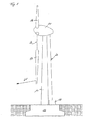
- FIG. 1 a tower 10 of a wind turbine is anchored to a foundation 12. At the top of the tower 10 is a nacelle 14, to which a first rotor blade 16 is attached.
- a winch 18 is also anchored on the foundation 12. From the winch 18, a traction cable 20 extends to the rear of the tower 10 (for this consideration, the front and the back of the tower 10 are those sides where the corresponding sections of the nacelle 14 are located) to the nacelle 14, passes through the nacelle and Exits from the nacelle 14 at a mounting opening provided for a second rotor blade 17 and extends downwardly to the rotor blade 17, which is attached to this traction cable and is pulled up by the winch or lowered to the ground. On the second rotor blade 17, an arrow 21 is shown, which symbolizes the use of a guide cable 21.
- the rotor blade 17 can be guided in a suitable manner, so that it can not strike unintentionally against the tower 10. Furthermore, it can be ensured by such a guide cable 21 that this rotor blade 17 does not touch down on the ground when it is lowered and damaged, but it can be pulled in the direction of the arrow and thus guided into a horizontal position.
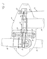
- FIG. 2 shows a simplified cross-sectional view of the nacelle 14.
- the head portion of the tower 10 is shown.
- a machine carrier 26 which carries the stator 28 with the stator 30.
- the machine carrier 26 carries a journal 32.
- this journal 32 of the rotor with the rotor blades 16, 17 and the rotor 30 of the generator is rotatably mounted.
- the pull cable 20 is shown, which enters the nacelle 14 at the rear.
- the passage opening for this traction cable 20 may also be a closable opening provided below the winch 22 in the bottom of the nacelle 14 anyway.
- the traction cable 20 runs after entering the nacelle 14 via the first guide roller 24 through a second cable feedthrough 36 (the first cable feedthrough is therefore the opening in the bottom of the nacelle 14), through a third cable feedthrough 37 to the guide roller 34 and from there to one fourth cable feedthrough 38 in the journal 32, z. B. to the rotor blade to be moved 17th
- the recovery of the pull cable 20 or its lowering on the way between the nacelle 14 and the winch 18 on the foundation 12 of the tower 10 can be supported by the winch 22.
- FIG. 3 shows a second embodiment of the invention.
- the components in this figure are designated by the same reference numerals as those in FIG. 2 ,
- the first embodiment of the invention is that here as a traction cable 20, the rope of the already existing in the wind turbine wind 22 is used.
- the carrying capacity of this winch is limited, but it can still components with lower weight z. B. lifted by the rotor blade opening in the front part of the nacelle 14.
- a pitch motor is called, so a motor, which serves to adjust a rotor blade. This would otherwise have to be lifted into the rear part of the gondola 14 and from there laboriously transported to the front part. This assumes, of course, that the rotor blade opening is open and not closed by a rotor blade.
- the rope course is then, as can be clearly seen in the figure, from the winch 22 via the first deflection roller 24, through the second rope feedthrough 36, the third rope feedthrough 37, over the second deflection roller 34 and through the fourth rope feedthrough 38.
- a cable guide or deflection roller can be arranged above the tower head, so that the rope then Steering roller are arranged above the tower head, so that the rope can then be lowered into the tower interior or pulled out of this. This can then be lifted or lowered as needed via the rope loads within the tower, especially in the area of the tower base, eg power cabinets, transformers, etc., which is advantageous if these parts must be brought out of the Turmfuß Scheme, which is regularly on side doors in Tower happens, but not all are at the level of the affected component to be replaced.
- any other type of cable guide can be provided, in which the cable can be passed through the machine support 26 into the tower.
- a further alternative may also be to accommodate the winch 18 itself not outside of the tower, but within the tower in the area of the tower base. Then the traction cable is always protected within the system and a lifting and lowering of cargo is possible in several places, once in the area of the rear nacelle (by pulley 24), once again in the area of the hub (via the roller 38) and lowering of components within the tower is also possible.
- a winch which is located at the foot of the wind energy plant, it does not necessarily have to be firmly connected to the foundation of the wind energy plant, but can also be mounted openly to the transport vehicle and connected thereto, so that a very flexible use of the winch is possible is. It is also possible to mount the winch on a frame, so that always a sufficiently large counterweight is ensured by the winds.
Landscapes
- Engineering & Computer Science (AREA)
- Life Sciences & Earth Sciences (AREA)
- Sustainable Development (AREA)
- Sustainable Energy (AREA)
- Chemical & Material Sciences (AREA)
- Combustion & Propulsion (AREA)
- Mechanical Engineering (AREA)
- General Engineering & Computer Science (AREA)
- Wind Motors (AREA)
- Shovels (AREA)
- Macromolecular Compounds Obtained By Forming Nitrogen-Containing Linkages In General (AREA)
Description
- Die vorliegende Erfindung betrifft eine Windenergieanlage sowie ein Verfahren zur Montage/Demontage von Komponenten einer Windenergieanlage.
- Windenergieanlagen sind seit geraumer Zeit bekannt. Durch die beträchtlichen Abmessungen und Gewichte moderner Anlagen müssen einerseits Komponenten einzeln zur Baustelle transportiert werden. Dort werden die Komponenten dann zusammengebaut. Dabei müssen inzwischen durchaus Lasten von 50 Tonnen und mehr gehoben werden.
- Andererseits müssen Lasten auch in beträchtliche Höhe von über 100 Metern gehoben werden. Zwar sind Winden in Windenergieanlagen und insbesondere dort in den Gondeln bekannt, jedoch befinden sich diese Winden meistens im hinteren Teil der Gondel der Windenergieanlage.
- Weiterhin ist aus der
WO 96/10130 - Alternativ sind Hebevorgänge natürlich unter Verwendung entsprechend großer und tragfähiger Kräne möglich, die wiederum nur mit hohem Aufwand bereit gestellt werden können Da auch der Aufwand zum Verfahren eines solchen Krans, also Abrüsten, Verfahren und erneut Aufrüsten, beträchtlich ist, bleibt der Kran in der Regel bei einer Windenergieanlage, bis deren Aufbau so weit fortgeschritten ist, dass der Kran dort nicht mehr benötigt wird. Erst dann wird der Kran zu der nächsten Baustelle transportiert. Dabei spielt die Entfernung zwischen diesen Baustellen eine untergeordnete Rolle, denn die zum Verlegen eines Krans erforderlichen Arbeitsgänge müssen stets ausgeführt werden, gleichgültig ob er lediglich um einige hundert Meter oder um einige hundert Kilometer verlegt wird.
- Natürlich erfordert auch der Austausch von Komponenten einer Windenergieanlage, wie z. B. der Rotorblätter, einen Kran, der entsprechend aufwändig transportiert werden muss.
- Weitere Hebevorgänge nach dem Stand der Technik sind aus
NL 1014553 US 3,829,064 bzw.JP 6135692 - Aufgabe der vorliegenden Erfindung ist es daher, ein Verfahren und eine Windenergieanlage der eingangs genannten Art derart weiterzubilden, dass ein Kran bei der Montage/Demontage von Komponenten einer Windenergieanlage in geringerem Umfang gebunden ist.
- Diese Aufgabe wird bei einer Windenergieanlage mit einem Fahrzeug gemäβ Anspruch 1 durch wenigstens eine Umlenkrolle und wenigstens eine Seildurchführung im Bereich des Turmkopfes zum Durchführen eines Zugseiles von einer Winde gelöst. Weiterhin wird die Aufgabe gelöst durch ein Verfahren zur Montage/Demontage von Komponenten einer Windenergieanlage gemäß Anspruch 4, mit den Schritten:
- Verlegen eines Zugseiles von der Winde zu wenigstens einer Umlenkrolle im Bereich Turmkopfes und weiter zu der montierenden/demontierenden Komponente,
- Anbringen des Zugseils an der Komponente, und
- Lösen und Herunterlassen bzw. Hochziehen und Befestigen der Komponente.
- Dabei liegt der Erfindung die Erkenntnis zu Grunde, dass wenigstens ein Teil der Komponenten einer Windenergieanlage auch ohne Hilfe eines Kranes montiert bzw. ausgetauscht werden kann, wenn eine geeignete Hebeeinrichtung zur Verfügung steht. Durch die erfindungsgemäße Lösung werden aufwändige Zusatzinstallationen an jeder Windenergieanlage vermieden. Trotzdem ist eine vielseitige Hebeeinrichtung mit geringem Aufwand schnell verfügbar.
- Dadurch ist die im hinteren Teil der Gondel bereits vorhandene Winde auch im vorderen Bereich der Gondel einsetzbar, ohne dass die Position der Winde innerhalb der Gondel verändert werden muss.
- In einer bevorzugten Weiterbildung der Erfindung ist eine Seildurchführung in der Gondel zum Durchführen eines Zugseils von einer Winde am Fuß der Windenergieanlage vorgesehen. Dadurch kann eine ausreichend starke Winde mit einem ausreichend tragfähigen Zugseil zum Heben bzw. Absenken schwerer Komponenten eingesetzt werden, so dass auch solche Komponenten ohne die Verwendung eines Kranes montiert bzw. ausgetauscht werden können. Es ist demnach völlig ausreichend, die Winde zu der Windenergieanlage zu transportieren, deren Zugseil mit der in der Windenergieanlage vorhandenen Winde bis in die Gondel hochzuziehen, dort über die Umlenkrolle(n) zu legen und dann die entsprechenden Montagen/Demontagen vorzunehmen. Dabei ist der Aufwand zum Transport einer Winde natürlich erheblich geringer als der Aufwand zum Transport eines ausreichend leistungsfähigen und insbesondere ausreichend großen Krans.
- Weitere vorteilhafte Ausführungsformen der Erfindung sind in den Unteransprüchen angegeben.
- Im Folgenden wird die Erfindung anhand der Figuren näher erläutert. Dabei zeigen:
- Fig. 1
- eine Windenergieanlage mit einer am Fuß des Turmes angeordneten Winde;
- Fig. 2
- eine vereinfachte Querschnittsansicht der Gondel mit einer ersten Ausführungsform der Erfindung; und
- Fig. 3
- eine vereinfachte Querschnittsansicht der Gondel mit einer zweiten Ausführungsform der Erfindung.
- In
Figur 1 ist ein Turm 10 einer Windenergieanlage auf einem Fundament 12 verankert. An der Spitze des Turmes 10 befindet sich eine Gondel 14, an welcher ein erstes Rotorblatt 16 befestigt ist. - Am Fuß des Turmes 10 ist eine Winde 18 ebenfalls auf dem Fundament 12 verankert. Von der Winde 18 verläuft ein Zugseil 20 an der Rückseite des Turmes 10 (für diese Betrachtung sind die Vorderseite und die Rückseite des Turmes 10 diejenigen Seiten, an denen sich die entsprechenden Abschnitte der Gondel 14 befinden) zu der Gondel 14, durchläuft die Gondel und tritt an einer für ein zweites Rotorblatt 17 vorgesehenen Montageöffnung wieder aus der Gondel 14 aus und verläuft nach unten zu dem Rotorblatt 17, das an diesem Zugseil befestigt ist und durch die Winde nach oben gezogen oder zum Boden hin herabgelassen wird. An dem zweiten Rotorblatt 17 ist ein Pfeil 21 dargestellt, der die Verwendung eines Führungsseiles 21 symbolisiert. Durch die Verwendung eines Führungsseiles 21 kann das Rotorblatt 17 in geeigneter Weise geführt werden, so dass es nicht unbeabsichtigt gegen den Turm 10 schlagen kann. Weiterhin kann durch ein solches Führungsseil 21 sichergestellt werden, dass dieses Rotorblatt 17 beim Herablassen nicht mit der Spitze auf dem Boden aufsetzt und beschädigt wird, sondern es kann in Richtung des Pfeiles gezogen und damit in eine horizontale Lage geführt werden.
-
Figur 2 zeigt eine vereinfachte Querschnittsansicht der Gondel 14. In dieser Figur ist der Kopfabschnitt des Turmes 10 dargestellt. Auf diesem Kopfabschnitt des Turmes 10 liegt ein Maschinenträger 26, der den Statorträger 28 mit dem Stator 30 trägt. Weiterhin trägt der Maschinenträger 26 einen Achszapfen 32. Auf diesem Achszapfen 32 ist der Rotor mit den Rotorblättern 16, 17 und der Läufer 30 des Generators drehbar gelagert. - An der von dem Statorträger 28 abgewandten Seite des Maschinenträgers 26 befindet sich eine in den meisten Windenergieanlagen bereits standardmäßig vorgesehene Winde 22. Dort befinden sich auch Haltestäbe 25, an deren von dem Maschinenträger 26 abgewandten Ende eine erste Umlenkrolle 24 vorgesehen ist. Eine zweite Umlenkrolle 34 befindet sich innerhalb des Achszapfens 32. Weiterhin ist in der Figur das Zugseil 20 dargestellt, das an der Rückseite in die Gondel 14 eintritt. Dabei kann die Durchgangsöffnung für dieses Zugseil 20 auch eine unterhalb der Winde 22 im Boden der Gondel 14 ohnehin vorgesehene, verschließbare Öffnung sein.
- Das Zugseil 20 verläuft nach dem Eintritt in die Gondel 14 über die erste Umlenkrolle 24 durch eine zweite Seildurchführung 36 (die erste Seildurchführung ist demnach die Öffnung im Boden der Gondel 14), durch eine dritte Seildurchführung 37 zu der Umlenkrolle 34 und von dort zu einer vierten Seildurchführung 38 in dem Achszapfen 32, z. B. zu dem zu bewegenden Rotorblatt 17.
- Das Heraufholen des Zugseiles 20 bzw. dessen Herablassen auf dem Weg zwischen der Gondel 14 und der Winde 18 am Fundament 12 des Turmes 10 kann durch die Winde 22 unterstützt werden.
-
Figur 3 zeigt eine zweite Ausführungsform der Erfindung. Die Komponenten in dieser Figur sind mit den gleichen Bezugszeichen bezeichnet wie diejenigen inFigur 2 . Der wesentliche Unterschied gegenüber der inFigur 2 gezeigten, ersten Ausführungsform der Erfindung besteht darin, dass hier als Zugseil 20 das Seil der ohnehin in der Windenergieanlage vorhandenen Winde 22 verwendet wird. Die Tragkraft dieser Winde ist zwar begrenzt, es können aber trotzdem Komponenten mit geringerem Gewicht z. B. durch die Rotorblatt-Öffnung in den vorderen Teil der Gondel 14 gehoben werden. Als Beispiel sei hier ein Pitchmotor genannt, also ein Motor, der der Verstellung eines Rotorblattes dient. Dieser müsste sonst in den hinteren Teil der Gondel 14 gehoben und von dort umständlich in den vorderen Teil transportiert werden. Dies setzt natürlich voraus, dass die Rotorblattöffnung offen und nicht durch ein Rotorblatt verschlossen ist. - Der Seilverlauf ist dann, wie in der Figur gut zu erkennen ist, von der Winde 22 über die erste Umlenkrolle 24, durch die zweite Seildurchführung 36, die dritte Seildurchführung 37, über die zweite Umlenkrolle 34 und durch die vierte Seildurchführung 38.
- Neben dem dargestellten und beschriebenen Beispiel sei auch auf eine weitere nicht dargestellte Alternative verwiesen. Hierbei kann eine Seilführung bzw. Umlenkrolle oberhalb des Turmkopfes angeordnet werden, so dass das Seil dann lenkrolle oberhalb des Turmkopfes angeordnet werden, so dass das Seil dann in das Turminnere herabgelassen bzw. aus diesem hochgezogen werden kann. Damit können dann über das Seil auch Lasten innerhalb des Turms, insbesondere im Bereich des Turmfußes, z.B. Leistungsschränke, Transformatoren etc. bei Bedarf hochgehoben oder gesenkt werden, was vorteilhaft ist, wenn diese Teile aus dem Turmfußbereich herausgebracht werden müssen, was regelmäßig über Seitentüren im Turm geschieht, die jedoch nicht sämtlich auf Höhe der betroffenen Komponente liegen, die ausgetauscht werden soll.
- Statt einer einfachen Umlenkrolle als Seil kann auch jede andere Art von Seilführung vorgesehen werden, in der das Seil durch den Maschinenträger 26 hindurch in den Turm geleitet werden kann.
- Eine weitere Alternative kann auch darin bestehen, die Winde 18 selbst nicht außerhalb des Turmes, sondern innerhalb des Turmes im Bereich des Turmfußes unterzubringen. Dann liegt das Zugseil stets geschützt innerhalb der Anlage und ein Heben und Senken von Fracht ist an mehreren Stellen möglich, einmal im Bereich der hinteren Gondel (durch Umlenkrolle 24), ein weiteres Mal im Bereich der Nabe (über die Rolle 38) und das Senken von Komponenten innerhalb des Turmes ist ebenfalls möglich.
- Es ist auch möglich, eine weitere Umlenkrolle (nach Art der Rolle 38) vorzusehen, die im Bereich der Nabenspitze 40 ausgebildet ist, so dass das Seil aus der Nabe der Windenergieanlage heraus an den Rotorblättern vorbeigeführt werden kann. Damit können dann Lasten vom Boden bis in den Bereich der Rotornabe hochgehoben werden, und zwar auch an den Rotorblättern vorbei. Wenn diese Last beispielsweise eine Arbeitsplattform ist, ist es möglich, das Personal direkt an den Rotorblättern außenseitig hoch und runterzufahren, um die Rotorblätter zu inspizieren oder im Bedarf Service- oder Reinigungsarbeiten vorzunehmen.
- Es versteht sich von selbst, dass dort wo notwendig, weitere Seitenführungs- oder Umlenkrollen innerhalb des Maschinenträgers, des Turms, der Gondel oder der Nabe vorgesehen werden können, ohne dass dies einer besonderen Erwähnung an dieser Stelle bedarf.
- Wird eine Winde eingesetzt, die sich am Fuß der Windenergieanlage befindet, so muss diese nicht zwangsläufig auch fest mit dem Fundament der Windenergieanlage verbunden sein, sondern kann auch offen ans Transportfahrzeug gelagert und mit diesem verbunden sein, so dass ein sehr flexibler Einsatz der Winde möglich ist. Auch ist es möglich, die Winde auf einem Gestell zu befestigen, so dass stets ein ausreichend großes Gegengewicht durch die Winde gewährleistet ist.
Claims (4)
- Windenergieanlage mit einem Fahrzeug, welches am Fuß der Windenergieanlage angeordnet ist umfrassend
wenigstens eine Umlenkrolle (24, 34) und wenigstens eine Seildurchführung (35, 36, 37, 38) im Bereich des Turmkopfes der Windenergieanlage zum Durchführen eines Zugseiles (20) von einer Winde (18, 22), welche außerhalb des Turms am Fuß des Windenergieanlage auf dem Fahrzeug gelagert und mit diesem verbunden ist. - Windenergieanlage nach Anspruch 1,
gekennzeichnet durch eine Selldurchführung (35) in der Gondel (14) der Windenergieanlage zum Durchführen eines Zugseiles (20) von der Winde (18) am Fuß der Windenergieanlage. - Windenergieanlage nach Anspruch 1 oder 2,
dadurch gekennzeichnet, dass eine zweite Seildurchführung vorgesehen ist, welche oberhalb des Turmkopfes der Windenergieanlaga ausgebildet ist und mittels welcher Komponenten der Windenergieanlage innerhalb des Turmes hebbar oder senkbar sind. - Verfahren zur Montage/Demontage von Komponenten einer Windenergieanlage, mit den Schriften;- Transport einer auf einem Transportfahrzeug gelagerten Winde (18,22), zum Fuß der Windenergieanlage,
Anordnung des Transportfahrzeugs am Fuß der Windenergieanlage,
wobei die Winde auf dem Transportfahrzeug bleibt,- Verlegen eines Zugseiles (20) von der Winde (18, 22) zu wenigstens einer Umlenkrolle (24, 34) im Bereich des Turmkopfes und weiter zu der zu montierenden/demontierenden Komponente /17),- Anbringen des Zugseiles an der Komponente (17) und- Lösen und Herunterlassen bzw. Hochziehen und Befestigen der Komponente (17).
Priority Applications (2)
| Application Number | Priority Date | Filing Date | Title |
|---|---|---|---|
| SI200332260T SI1516119T1 (sl) | 2002-06-01 | 2003-05-23 | Postopek za montaĹľo/demontaĹľo komoponent vetrne elektrarne |
| CY20131100570T CY1114235T1 (el) | 2002-06-01 | 2013-07-08 | Μεθοδος για την εγκατασταση/απεγκατασταση συστατικων στοιχειων μιας εγκαταστασης αιολικης ενεργειας |
Applications Claiming Priority (3)
| Application Number | Priority Date | Filing Date | Title |
|---|---|---|---|
| DE10224439 | 2002-06-01 | ||
| DE10224439A DE10224439C5 (de) | 2002-06-01 | 2002-06-01 | Verfahren zur Montage/Demontage von Komponenten einer Windenergieanlage |
| PCT/EP2003/005401 WO2003102409A1 (de) | 2002-06-01 | 2003-05-23 | Verfahren zur montage/demontage von komponenten einer windenergieanlage |
Publications (2)
| Publication Number | Publication Date |
|---|---|
| EP1516119A1 EP1516119A1 (de) | 2005-03-23 |
| EP1516119B1 true EP1516119B1 (de) | 2013-05-01 |
Family
ID=29557470
Family Applications (1)
| Application Number | Title | Priority Date | Filing Date |
|---|---|---|---|
| EP03735446.1A Expired - Lifetime EP1516119B1 (de) | 2002-06-01 | 2003-05-23 | Verfahren zur montage/demontage von komponenten einer windenergieanlage |
Country Status (19)
| Country | Link |
|---|---|
| US (1) | US8052396B2 (de) |
| EP (1) | EP1516119B1 (de) |
| JP (1) | JP4233522B2 (de) |
| KR (1) | KR100646740B1 (de) |
| CN (1) | CN100390404C (de) |
| AR (1) | AR039920A1 (de) |
| AU (1) | AU2003237665B2 (de) |
| BR (1) | BR0311380A (de) |
| CA (1) | CA2486779C (de) |
| CY (1) | CY1114235T1 (de) |
| DE (1) | DE10224439C5 (de) |
| DK (1) | DK1516119T3 (de) |
| ES (1) | ES2421739T3 (de) |
| MA (1) | MA27211A1 (de) |
| NO (1) | NO338454B1 (de) |
| PL (1) | PL210835B1 (de) |
| PT (1) | PT1516119E (de) |
| SI (1) | SI1516119T1 (de) |
| WO (1) | WO2003102409A1 (de) |
Families Citing this family (60)
| Publication number | Priority date | Publication date | Assignee | Title |
|---|---|---|---|---|
| DE10303555B4 (de) | 2003-01-29 | 2007-01-25 | Aloys Wobben | Verfahren zur kranlosen Montage eines Rotorblattes einer Windenergieanlage |
| DE102004056340B4 (de) * | 2004-11-22 | 2010-11-18 | Repower Systems Ag | Vorrichtung und Verfahren zur Montage und/oder Demontage eines Bauteils einer Windkraftanlage |
| AU2007228500A1 (en) * | 2006-03-23 | 2007-09-27 | Clipper Windpower, Inc. | Wind turbine nacelle with integral service crane for accessing turbine components |
| US7614850B2 (en) * | 2006-07-11 | 2009-11-10 | General Electric Company | Apparatus for assembling rotary machines |
| AU2007304635A1 (en) | 2006-10-02 | 2008-04-10 | Upraft Gmbh | Hoisting device |
| ES2322000B1 (es) * | 2006-12-14 | 2010-03-11 | GAMESA INNOVATION & TECHNOLOGY, S.L. | Un metodo para montar el rotor de un aerogenerador. |
| JP5055023B2 (ja) | 2007-05-25 | 2012-10-24 | 三菱重工業株式会社 | 風力発電装置のロータ取付け方法および風力発電装置の建設方法 |
| JP4885071B2 (ja) * | 2007-06-19 | 2012-02-29 | 三菱重工業株式会社 | 風車用設備の交換方法 |
| JP4885073B2 (ja) * | 2007-06-20 | 2012-02-29 | 三菱重工業株式会社 | 風車回転翼の吊下げ装置、風車回転翼の取付け方法、および風力発電装置の建設方法 |
| WO2009101697A1 (ja) * | 2008-02-15 | 2009-08-20 | Sakuraigiken Co., Ltd. | 風力発電設備の風車羽根のメンテナンス工法及びメンテナンス装置 |
| NL1035301C1 (nl) * | 2008-04-16 | 2008-06-04 | Dhlc | Lift- en daalmethode middels een demontabele hijsinrichting. |
| KR101038641B1 (ko) * | 2008-09-01 | 2011-06-03 | 두산중공업 주식회사 | 풍력터빈설비의 유지 보수 시스템 |
| WO2010079150A2 (de) | 2009-01-06 | 2010-07-15 | Kenersys Gmbh | Verfahren zum vertikalen bewegen von lasten entlang einer windenergieanlage |
| ES2371893B2 (es) * | 2009-02-02 | 2012-05-16 | Gamesa Innovation & Technology, S.L. | Método y dispositivo de manipulación o transporte de palas de aerogeneradores. |
| KR101054919B1 (ko) * | 2009-04-03 | 2011-08-05 | 주식회사 디엠에스 | 풍력 발전기 |
| US8443571B2 (en) * | 2009-09-19 | 2013-05-21 | Btpatent Llc | Wind power equipment and assembly |
| US8118552B2 (en) * | 2009-10-06 | 2012-02-21 | General Electric Company | Apparatus and method for manipulating a component of a wind turbine |
| CN101929443A (zh) * | 2009-10-26 | 2010-12-29 | 华锐风电科技(集团)股份有限公司 | 风电机组叶片自更换装置及其工作方法 |
| DK177083B1 (da) * | 2009-10-28 | 2011-06-27 | Liftra Aps | Indretning for tilvejebringelse af adgang og transport af gods til og fra en vindmøllekonstruktion over terrænniveau |
| TWI392799B (zh) * | 2009-11-12 | 2013-04-11 | Hiwin Mikrosystem Corp | 風力發電機之風車裝置 |
| EP2499362A2 (de) | 2009-11-13 | 2012-09-19 | Suzlon Energy GmbH | Antriebseinheit für windturbine |
| ES2360779B1 (es) * | 2009-11-20 | 2012-04-19 | Gamesa Innovation & Technology S.L | Aerogenerador con dispositivos internos de transporte. |
| CN102762849A (zh) * | 2009-11-30 | 2012-10-31 | 剪式风能技术公司 | 风轮机桨叶放下设备 |
| DE102009056245B4 (de) * | 2009-12-01 | 2014-02-20 | Aerodyn Engineering Gmbh | Windenergieanlage mit Hebevorrichtung |
| GB2475865A (en) * | 2009-12-02 | 2011-06-08 | Vestas Wind Sys As | Anti-Oscillation Apparatus And Technique For Securing Wind Turbine Blades Against Oscillations |
| KR101021447B1 (ko) | 2010-02-10 | 2011-03-15 | 미츠비시 쥬고교 가부시키가이샤 | 풍력 발전 장치의 로터 헤드 내 기기 승강 방법 |
| JP4551491B1 (ja) * | 2010-02-10 | 2010-09-29 | 三菱重工業株式会社 | 風力発電装置のロータヘッド内機器昇降方法 |
| GB201003002D0 (en) | 2010-02-23 | 2010-04-07 | Artemis Intelligent Power Ltd | Fluid working machine and method of operating fluid working machine |
| DE102010043435A1 (de) * | 2010-11-04 | 2012-05-10 | Aloys Wobben | Windenergieanlage |
| GB2487083A (en) * | 2011-01-07 | 2012-07-11 | Vestas Wind Sys As | Wind turbine blade bearing removal apparatus and method |
| US8807923B2 (en) * | 2011-02-07 | 2014-08-19 | Vestas Wind Systems A/S | Access apparatus for a wind turbine and method of using same |
| ES2587265T3 (es) * | 2011-02-07 | 2016-10-21 | Vestas Wind Systems A/S | Aparato de acceso para una turbina eólica y método de uso del mismo |
| US20120260590A1 (en) | 2011-04-12 | 2012-10-18 | Lambert Walter L | Parallel Wire Cable |
| US8474219B2 (en) * | 2011-07-13 | 2013-07-02 | Ultimate Strength Cable, LLC | Stay cable for structures |
| DE102011017801B8 (de) | 2011-04-29 | 2013-05-08 | Wobben Properties Gmbh | Windenergieanlage mit einer Mehrzahl von Verschiebeeinheiten zur Montage oder Demontage von Rotorblättern und Verfahren hierzu |
| EP2520533B2 (de) * | 2011-05-05 | 2019-06-12 | Siemens Aktiengesellschaft | Wartungskran für eine Windturbine |
| CN103133267B (zh) * | 2011-12-02 | 2015-11-25 | 新疆金风科技股份有限公司 | 风力发电机组的叶片更换方法及叶片更换辅助系统 |
| KR101362936B1 (ko) * | 2012-01-17 | 2014-02-14 | 삼성중공업 주식회사 | 풍력발전기의 블레이드 이동 장치, 이를 이용한 피치 베어링 수리 방법 및 이를 구비한 풍력 발전기 |
| PL2657519T3 (pl) * | 2012-04-26 | 2015-11-30 | Siemens Ag | Turbina wiatrowa |
| US9745953B2 (en) * | 2012-10-23 | 2017-08-29 | General Electric Company | Method and system for replacing a single wind turbine blade |
| US9027243B2 (en) | 2012-10-23 | 2015-05-12 | General Electric Company | Method and system for replacing a single wind turbine blade |
| DE102013214920A1 (de) | 2013-07-30 | 2015-02-05 | Wobben Properties Gmbh | Windenergieanlage |
| JP6320738B2 (ja) * | 2013-12-06 | 2018-05-09 | 株式会社日立製作所 | 風力発電設備および風力発電設備の保守方法 |
| US10113530B2 (en) | 2014-02-20 | 2018-10-30 | General Electric Company | Methods and systems for removing and/or installing wind turbine rotor blades |
| US9638163B2 (en) | 2014-02-20 | 2017-05-02 | General Electric Company | Methods and systems for removing and/or installing wind turbine rotor blades |
| US9651021B2 (en) | 2014-09-09 | 2017-05-16 | General Electric Company | System and method for removing and/or installing a rotor blade of a wind turbine |
| US9890022B2 (en) | 2015-05-07 | 2018-02-13 | General Electric Company | Method for suspending a rotor blade from a hub of a wind turbine |
| US9821417B2 (en) | 2015-05-07 | 2017-11-21 | General Electric Company | System and method for replacing a pitch bearing |
| US10066601B2 (en) | 2015-10-22 | 2018-09-04 | General Electric Company | System and method for manufacturing wind turbine rotor blades for simplified installation and removal |
| DE102016111514A1 (de) * | 2016-06-23 | 2017-12-28 | Wobben Properties Gmbh | Verfahren zum Errichten einer Windenergieanlage und Hebetraverse zur Montage eines Rotorblatts einer Windenergieanlage |
| WO2018162101A1 (en) * | 2017-03-07 | 2018-09-13 | Siemens Wind Power A/S | Assembly system for assembling of a first wind turbine component of a wind turbine and second wind turbine component of the wind turbine and method for assembling of a wind turbine by using the assembly system |
| ES2876008T3 (es) | 2017-03-29 | 2021-11-11 | Gen Electric | Conjunto de grúa de buje para una turbina eólica |
| US10508645B2 (en) | 2017-07-17 | 2019-12-17 | General Electric Company | System and method for suspending a rotor blade of a wind turbine uptower |
| EP3502465B1 (de) * | 2017-12-22 | 2020-12-09 | General Electric Company | Hubzubehör für windturbinen, kits und verfahren |
| DE102018105276A1 (de) | 2018-03-07 | 2019-09-12 | Max Bögl Wind AG | Verfahren zum Einbringen von Spanngliedern in einen Turm, Montagevorrichtung, Abtrommelvorrichtung und Adaptervorrichtung |
| DK181351B1 (en) * | 2019-03-01 | 2023-08-23 | Liftra Ip Aps | Crane system for hoisting of wind turbine components and method for moving a burden |
| EP3770420B1 (de) * | 2019-07-23 | 2022-09-07 | Siemens Gamesa Renewable Energy A/S | Verfahren zur verbindung einer schaufel mit einer nabe und verfahren zur lösung einer schaufel von einer nabe |
| NO346461B1 (no) * | 2020-10-29 | 2022-08-29 | Turbineco As | Anordning og metode ved montering og demontering av vinger på en vindturbin |
| AU2022491199A1 (en) * | 2022-12-20 | 2025-06-19 | Nabrawind Technologies, S.L. | Guiding system for exchanging a wind turbine blade and use method |
| US12590569B2 (en) | 2023-09-01 | 2026-03-31 | CAD Wind Turbines LLC | Wind turbine assembly and method of assembling a wind turbine assembly |
Family Cites Families (23)
| Publication number | Priority date | Publication date | Assignee | Title |
|---|---|---|---|---|
| US3404247A (en) * | 1966-03-08 | 1968-10-01 | Gen Electric | Pressure responsive protective means for vacuum type circuit interrupters |
| US3829064A (en) * | 1973-01-05 | 1974-08-13 | Jackson Communication Corp | Winch system |
| DE2823525C2 (de) | 1978-05-30 | 1985-05-09 | M.A.N. Maschinenfabrik Augsburg-Nuernberg Ag, 8000 Muenchen | Windenergieanlage und Verfahren zu deren Errichten |
| US4236873A (en) | 1978-09-20 | 1980-12-02 | United Technologies Corporation | Wind turbine blade retention device |
| JPS56143369A (en) * | 1980-04-07 | 1981-11-09 | Agency Of Ind Science & Technol | Wind force prime mover using propeller |
| DE3103710C2 (de) | 1981-02-04 | 1983-03-24 | Messerschmitt-Bölkow-Blohm GmbH, 8000 München | "Rotor in Schalenbauweise" |
| US4752806A (en) | 1986-06-23 | 1988-06-21 | Xerox Corporation | Multi-mode imaging system |
| JPH0351182A (ja) | 1989-07-19 | 1991-03-05 | Matsushita Electric Ind Co Ltd | 光記録媒体 |
| JPH0742074B2 (ja) * | 1992-10-29 | 1995-05-10 | 伸弘 都築 | 自動車等重量物体に装着される牽引装置 |
| AT401674B (de) * | 1994-09-26 | 1996-11-25 | Hehenberger Gerald Dipl Ing | Windkraftanlage |
| US6494437B1 (en) * | 1995-10-24 | 2002-12-17 | Mark L. Boyer | Boom mounted winch |
| EP0868389A1 (de) * | 1995-12-08 | 1998-10-07 | Tymon Corporation Limited | Verfahren und vorrichtung zum heben einer last auf einen turm |
| DE29603278U1 (de) | 1996-02-23 | 1996-04-25 | Beyer, Reinhard, 23769 Bannesdorf | Vorrichtung zur Reinigung von Rotorblättern von Windkraftanlagen |
| DE19647515B4 (de) * | 1996-11-16 | 2010-04-15 | Gerd-Albrecht Otto | Windkonvertermontageeinrichtung |
| DE19726408C1 (de) | 1997-06-21 | 1999-03-18 | Gerhard Reineke Schlosserei Un | Arbeitsbühne |
| DK173530B2 (da) * | 1999-11-17 | 2005-07-18 | Siemens Wind Power As | Fremgangsmåde til montering af hovedkomponenter i kabine på vindmölle og en sådan kabine til vindmölle |
| DE19955516C1 (de) * | 1999-11-18 | 2001-12-20 | Tacke Windenergie Gmbh | Windkraftanlage und Verfahren zum Aus- und Einbau der Hauptkomponenten des Maschinengehäuses einer Windkraftanlage |
| US20010038207A1 (en) | 2000-05-02 | 2001-11-08 | Willis Jeffrey O. | Method and means for mounting a wind turbine on a tower |
| DE10111523C2 (de) | 2001-03-09 | 2003-01-30 | Erwin Keller | Transportable Arbeitsvorrichtung mit Hebegerät für Arbeiten an einer Windkraftanlage |
| AU2002362203B2 (en) | 2001-12-06 | 2009-03-26 | Pp Energy Aps | Method and apparatus for treatment of a rotor blade on a windmill |
| BR0215738B1 (pt) * | 2002-05-27 | 2011-12-27 | mÉtodos de manipulaÇço de lÂminas de turbina de vento e montagem de referidas lÂminas sobre uma turbina de vento, sistema e unidade de agarramento para a manipulaÇço de uma lÂmina de turbina de vento. | |
| EP1534953A1 (de) | 2002-09-04 | 2005-06-01 | PP Energy ApS | Verfahren und vorrichtung zum anheben und/oder absenken von objekten an einer windturbine oder dergleichen und verwendungen davon |
| CA2938133C (en) * | 2014-01-30 | 2017-08-29 | Nissan Motor Co., Ltd. | A fuel cell system with wetness and anode gas concentration control |
-
2002
- 2002-06-01 DE DE10224439A patent/DE10224439C5/de not_active Expired - Lifetime
-
2003
- 2003-05-23 EP EP03735446.1A patent/EP1516119B1/de not_active Expired - Lifetime
- 2003-05-23 JP JP2004509270A patent/JP4233522B2/ja not_active Expired - Fee Related
- 2003-05-23 BR BR0311380-9A patent/BR0311380A/pt not_active Application Discontinuation
- 2003-05-23 CA CA002486779A patent/CA2486779C/en not_active Expired - Fee Related
- 2003-05-23 CN CNB03812632XA patent/CN100390404C/zh not_active Expired - Lifetime
- 2003-05-23 KR KR1020047018330A patent/KR100646740B1/ko not_active Expired - Fee Related
- 2003-05-23 AU AU2003237665A patent/AU2003237665B2/en not_active Ceased
- 2003-05-23 DK DK03735446.1T patent/DK1516119T3/da active
- 2003-05-23 ES ES03735446T patent/ES2421739T3/es not_active Expired - Lifetime
- 2003-05-23 PL PL372194A patent/PL210835B1/pl unknown
- 2003-05-23 SI SI200332260T patent/SI1516119T1/sl unknown
- 2003-05-23 WO PCT/EP2003/005401 patent/WO2003102409A1/de not_active Ceased
- 2003-05-23 US US10/516,570 patent/US8052396B2/en not_active Expired - Lifetime
- 2003-05-23 PT PT37354461T patent/PT1516119E/pt unknown
- 2003-05-30 AR ARP030101909A patent/AR039920A1/es not_active Application Discontinuation
-
2004
- 2004-11-30 MA MA27976A patent/MA27211A1/fr unknown
- 2004-12-29 NO NO20045695A patent/NO338454B1/no not_active IP Right Cessation
-
2013
- 2013-07-08 CY CY20131100570T patent/CY1114235T1/el unknown
Also Published As
| Publication number | Publication date |
|---|---|
| WO2003102409A8 (de) | 2005-03-24 |
| DE10224439B4 (de) | 2008-01-03 |
| EP1516119A1 (de) | 2005-03-23 |
| PT1516119E (pt) | 2013-06-28 |
| DE10224439A1 (de) | 2003-12-18 |
| JP4233522B2 (ja) | 2009-03-04 |
| US8052396B2 (en) | 2011-11-08 |
| MA27211A1 (fr) | 2005-01-03 |
| PL210835B1 (pl) | 2012-03-30 |
| CA2486779A1 (en) | 2003-12-11 |
| CY1114235T1 (el) | 2016-08-31 |
| AR039920A1 (es) | 2005-03-09 |
| WO2003102409A1 (de) | 2003-12-11 |
| SI1516119T1 (sl) | 2013-06-28 |
| DE10224439C5 (de) | 2009-12-31 |
| KR20050007542A (ko) | 2005-01-19 |
| KR100646740B1 (ko) | 2006-11-23 |
| NO20045695L (no) | 2004-12-29 |
| ES2421739T3 (es) | 2013-09-05 |
| CN1659374A (zh) | 2005-08-24 |
| JP2005531709A (ja) | 2005-10-20 |
| AU2003237665B2 (en) | 2007-11-08 |
| DK1516119T3 (da) | 2013-07-15 |
| CA2486779C (en) | 2009-02-03 |
| AU2003237665A1 (en) | 2003-12-19 |
| US20060151767A1 (en) | 2006-07-13 |
| BR0311380A (pt) | 2005-03-15 |
| CN100390404C (zh) | 2008-05-28 |
| NO338454B1 (no) | 2016-08-15 |
| PL372194A1 (en) | 2005-07-11 |
Similar Documents
| Publication | Publication Date | Title |
|---|---|---|
| EP1516119B1 (de) | Verfahren zur montage/demontage von komponenten einer windenergieanlage | |
| DE60011737T3 (de) | Methode zum Montieren der Komponenten einer Windkraftanlage | |
| DE102009056245B4 (de) | Windenergieanlage mit Hebevorrichtung | |
| DE10303555B4 (de) | Verfahren zur kranlosen Montage eines Rotorblattes einer Windenergieanlage | |
| EP2163504B1 (de) | Verfahren zum Hochheben von Komponenten von Windenenergieanlagen | |
| EP2764237B1 (de) | Verfahren und vorrichtung zum montieren eines rotors einer windenergieanlage | |
| EP2909470B1 (de) | Arbeitsbühne um die schraubverbindungen von windenergieanlagen-turmsegment-teilen zu überprüfen | |
| EP1857670A1 (de) | Verfahren und Vorrichtung zum Errichten eines aus einzelnen Turmsegmenten zusammengesetzten Turms einer Windenergieanlage | |
| EP1101934A2 (de) | Windkraftanlage mit bewegbarem Bordkran | |
| EP1251269A2 (de) | Windkraftanlage mit verschiebbarem Behälter | |
| EP2014912A2 (de) | Windkraftanlage mit Gondel und Verfahren zum Erstellen einer solchen Windkraftanlage | |
| EP2723670A1 (de) | Lasthandhabungsvorrichtung zum anheben und verfahren zur montage von rotorblättern einer windenergieanlage | |
| EP3399185B1 (de) | Einhausung für eine gondel einer windenergieanlage | |
| DE102009000963A1 (de) | Verfahren und Fördermittel zur Montage eines Turms sowie Turmsegment | |
| DE102017217513A1 (de) | Höhenverstellbarer Turm mit einem Führungssystem | |
| EP3404259B1 (de) | Verfahren, lastaufnahmemittel und montagesystem zum zusammenbauen einer windenergieanlage | |
| WO2020057864A1 (de) | Windenergieanlagen-turmsegment für einen windenergieanlagen-turm und verfahren | |
| DE202011001850U1 (de) | Kran | |
| EP3746657B1 (de) | Gondel einer windenergieanlage, sowie windenergieanlage mit gondel und verfahren zur wartung einer solchen windenergieanlage | |
| DE202018101621U1 (de) | System zum Anheben und Absenken von Lasten an einer Windenergieanlage | |
| DE102017217514A1 (de) | Höhenverstellbarer Turm mit überlappenden Turmkomponenten | |
| EP3839252A1 (de) | Montagevorrichtung für rotorblätter einer windenergieanlage | |
| DE102024108609A1 (de) | Errichtungsvorrichtung und Verfahren zum Errichten einer Windkraftanlage | |
| DE102013202156A1 (de) | Windkraftanlage | |
| WO2010079150A2 (de) | Verfahren zum vertikalen bewegen von lasten entlang einer windenergieanlage |
Legal Events
| Date | Code | Title | Description |
|---|---|---|---|
| PUAI | Public reference made under article 153(3) epc to a published international application that has entered the european phase |
Free format text: ORIGINAL CODE: 0009012 |
|
| 17P | Request for examination filed |
Effective date: 20050103 |
|
| AK | Designated contracting states |
Kind code of ref document: A1 Designated state(s): AT BE BG CH CY CZ DE DK EE ES FI FR GB GR HU IE IT LI LU MC NL PT RO SE SI SK TR |
|
| AX | Request for extension of the european patent |
Extension state: AL LT LV MK |
|
| DAX | Request for extension of the european patent (deleted) | ||
| 17Q | First examination report despatched |
Effective date: 20070706 |
|
| R17C | First examination report despatched (corrected) |
Effective date: 20070706 |
|
| GRAP | Despatch of communication of intention to grant a patent |
Free format text: ORIGINAL CODE: EPIDOSNIGR1 |
|
| RAP1 | Party data changed (applicant data changed or rights of an application transferred) |
Owner name: WOBBEN PROPERTIES GMBH |
|
| RIN1 | Information on inventor provided before grant (corrected) |
Inventor name: WOBBEN, ALOYS |
|
| GRAS | Grant fee paid |
Free format text: ORIGINAL CODE: EPIDOSNIGR3 |
|
| GRAA | (expected) grant |
Free format text: ORIGINAL CODE: 0009210 |
|
| AK | Designated contracting states |
Kind code of ref document: B1 Designated state(s): AT BE BG CH CY CZ DE DK EE ES FI FR GB GR HU IE IT LI LU MC NL PT RO SE SI SK TR |
|
| REG | Reference to a national code |
Ref country code: GB Ref legal event code: FG4D Free format text: NOT ENGLISH |
|
| REG | Reference to a national code |
Ref country code: AT Ref legal event code: REF Ref document number: 610108 Country of ref document: AT Kind code of ref document: T Effective date: 20130515 Ref country code: CH Ref legal event code: EP |
|
| REG | Reference to a national code |
Ref country code: IE Ref legal event code: FG4D Free format text: LANGUAGE OF EP DOCUMENT: GERMAN |
|
| REG | Reference to a national code |
Ref country code: CH Ref legal event code: NV Representative=s name: WAGNER PATENT AG, CH |
|
| REG | Reference to a national code |
Ref country code: PT Ref legal event code: SC4A Free format text: AVAILABILITY OF NATIONAL TRANSLATION Effective date: 20130620 |
|
| REG | Reference to a national code |
Ref country code: DE Ref legal event code: R096 Ref document number: 50314783 Country of ref document: DE Effective date: 20130704 |
|
| REG | Reference to a national code |
Ref country code: DK Ref legal event code: T3 |
|
| REG | Reference to a national code |
Ref country code: RO Ref legal event code: EPE |
|
| REG | Reference to a national code |
Ref country code: SE Ref legal event code: TRGR |
|
| REG | Reference to a national code |
Ref country code: SK Ref legal event code: T3 Ref document number: E 14324 Country of ref document: SK |
|
| REG | Reference to a national code |
Ref country code: ES Ref legal event code: FG2A Ref document number: 2421739 Country of ref document: ES Kind code of ref document: T3 Effective date: 20130905 |
|
| REG | Reference to a national code |
Ref country code: NL Ref legal event code: T3 |
|
| REG | Reference to a national code |
Ref country code: GR Ref legal event code: EP Ref document number: 20130401550 Country of ref document: GR Effective date: 20130829 |
|
| REG | Reference to a national code |
Ref country code: EE Ref legal event code: FG4A Ref document number: E008313 Country of ref document: EE Effective date: 20130710 |
|
| PG25 | Lapsed in a contracting state [announced via postgrant information from national office to epo] |
Ref country code: MC Free format text: LAPSE BECAUSE OF FAILURE TO SUBMIT A TRANSLATION OF THE DESCRIPTION OR TO PAY THE FEE WITHIN THE PRESCRIBED TIME-LIMIT Effective date: 20130501 |
|
| PLBE | No opposition filed within time limit |
Free format text: ORIGINAL CODE: 0009261 |
|
| STAA | Information on the status of an ep patent application or granted ep patent |
Free format text: STATUS: NO OPPOSITION FILED WITHIN TIME LIMIT |
|
| REG | Reference to a national code |
Ref country code: CH Ref legal event code: PCAR Free format text: NEW ADDRESS: BAECHERSTRASSE 9, 8832 WOLLERAU (CH) |
|
| 26N | No opposition filed |
Effective date: 20140204 |
|
| REG | Reference to a national code |
Ref country code: DE Ref legal event code: R097 Ref document number: 50314783 Country of ref document: DE Effective date: 20140204 |
|
| REG | Reference to a national code |
Ref country code: HU Ref legal event code: AG4A Ref document number: E019390 Country of ref document: HU |
|
| REG | Reference to a national code |
Ref country code: FR Ref legal event code: PLFP Year of fee payment: 14 |
|
| REG | Reference to a national code |
Ref country code: FR Ref legal event code: PLFP Year of fee payment: 15 |
|
| REG | Reference to a national code |
Ref country code: FR Ref legal event code: PLFP Year of fee payment: 16 |
|
| PGFP | Annual fee paid to national office [announced via postgrant information from national office to epo] |
Ref country code: LU Payment date: 20180523 Year of fee payment: 16 |
|
| PGFP | Annual fee paid to national office [announced via postgrant information from national office to epo] |
Ref country code: SK Payment date: 20180516 Year of fee payment: 16 Ref country code: CH Payment date: 20180523 Year of fee payment: 16 Ref country code: FI Payment date: 20180517 Year of fee payment: 16 Ref country code: CZ Payment date: 20180515 Year of fee payment: 16 Ref country code: IE Payment date: 20180521 Year of fee payment: 16 Ref country code: EE Payment date: 20180521 Year of fee payment: 16 |
|
| PGFP | Annual fee paid to national office [announced via postgrant information from national office to epo] |
Ref country code: RO Payment date: 20180516 Year of fee payment: 16 Ref country code: IT Payment date: 20180518 Year of fee payment: 16 Ref country code: SI Payment date: 20180515 Year of fee payment: 16 Ref country code: TR Payment date: 20180511 Year of fee payment: 16 Ref country code: GR Payment date: 20180521 Year of fee payment: 16 |
|
| PGFP | Annual fee paid to national office [announced via postgrant information from national office to epo] |
Ref country code: CY Payment date: 20180518 Year of fee payment: 16 |
|
| REG | Reference to a national code |
Ref country code: EE Ref legal event code: MM4A Ref document number: E008313 Country of ref document: EE Effective date: 20190531 |
|
| REG | Reference to a national code |
Ref country code: CH Ref legal event code: PL |
|
| PG25 | Lapsed in a contracting state [announced via postgrant information from national office to epo] |
Ref country code: SK Free format text: LAPSE BECAUSE OF NON-PAYMENT OF DUE FEES Effective date: 20190523 Ref country code: BG Free format text: LAPSE BECAUSE OF NON-PAYMENT OF DUE FEES Effective date: 20191130 Ref country code: LI Free format text: LAPSE BECAUSE OF NON-PAYMENT OF DUE FEES Effective date: 20190531 Ref country code: EE Free format text: LAPSE BECAUSE OF NON-PAYMENT OF DUE FEES Effective date: 20190531 Ref country code: CZ Free format text: LAPSE BECAUSE OF NON-PAYMENT OF DUE FEES Effective date: 20190523 Ref country code: RO Free format text: LAPSE BECAUSE OF NON-PAYMENT OF DUE FEES Effective date: 20190523 Ref country code: CH Free format text: LAPSE BECAUSE OF NON-PAYMENT OF DUE FEES Effective date: 20190531 Ref country code: HU Free format text: LAPSE BECAUSE OF NON-PAYMENT OF DUE FEES Effective date: 20190524 Ref country code: CY Free format text: LAPSE BECAUSE OF NON-PAYMENT OF DUE FEES Effective date: 20190523 Ref country code: FI Free format text: LAPSE BECAUSE OF NON-PAYMENT OF DUE FEES Effective date: 20190523 |
|
| REG | Reference to a national code |
Ref country code: SK Ref legal event code: MM4A Ref document number: E 14324 Country of ref document: SK Effective date: 20190523 |
|
| REG | Reference to a national code |
Ref country code: BE Ref legal event code: MM Effective date: 20190531 |
|
| PG25 | Lapsed in a contracting state [announced via postgrant information from national office to epo] |
Ref country code: GR Free format text: LAPSE BECAUSE OF NON-PAYMENT OF DUE FEES Effective date: 20191205 Ref country code: LU Free format text: LAPSE BECAUSE OF NON-PAYMENT OF DUE FEES Effective date: 20190523 Ref country code: SI Free format text: LAPSE BECAUSE OF NON-PAYMENT OF DUE FEES Effective date: 20190524 |
|
| PG25 | Lapsed in a contracting state [announced via postgrant information from national office to epo] |
Ref country code: IE Free format text: LAPSE BECAUSE OF NON-PAYMENT OF DUE FEES Effective date: 20190523 Ref country code: IT Free format text: LAPSE BECAUSE OF NON-PAYMENT OF DUE FEES Effective date: 20190523 |
|
| PG25 | Lapsed in a contracting state [announced via postgrant information from national office to epo] |
Ref country code: BE Free format text: LAPSE BECAUSE OF NON-PAYMENT OF DUE FEES Effective date: 20190531 |
|
| PGFP | Annual fee paid to national office [announced via postgrant information from national office to epo] |
Ref country code: PT Payment date: 20200518 Year of fee payment: 18 Ref country code: ES Payment date: 20200618 Year of fee payment: 18 |
|
| PGFP | Annual fee paid to national office [announced via postgrant information from national office to epo] |
Ref country code: SE Payment date: 20200525 Year of fee payment: 18 |
|
| PGFP | Annual fee paid to national office [announced via postgrant information from national office to epo] |
Ref country code: AT Payment date: 20200515 Year of fee payment: 18 |
|
| REG | Reference to a national code |
Ref country code: SE Ref legal event code: EUG |
|
| REG | Reference to a national code |
Ref country code: AT Ref legal event code: MM01 Ref document number: 610108 Country of ref document: AT Kind code of ref document: T Effective date: 20210523 |
|
| PG25 | Lapsed in a contracting state [announced via postgrant information from national office to epo] |
Ref country code: SE Free format text: LAPSE BECAUSE OF NON-PAYMENT OF DUE FEES Effective date: 20210524 Ref country code: PT Free format text: LAPSE BECAUSE OF NON-PAYMENT OF DUE FEES Effective date: 20211123 Ref country code: AT Free format text: LAPSE BECAUSE OF NON-PAYMENT OF DUE FEES Effective date: 20210523 |
|
| PG25 | Lapsed in a contracting state [announced via postgrant information from national office to epo] |
Ref country code: TR Free format text: LAPSE BECAUSE OF NON-PAYMENT OF DUE FEES Effective date: 20190523 |
|
| PGFP | Annual fee paid to national office [announced via postgrant information from national office to epo] |
Ref country code: NL Payment date: 20220518 Year of fee payment: 20 |
|
| PGFP | Annual fee paid to national office [announced via postgrant information from national office to epo] |
Ref country code: GB Payment date: 20220523 Year of fee payment: 20 Ref country code: FR Payment date: 20220523 Year of fee payment: 20 Ref country code: DK Payment date: 20220523 Year of fee payment: 20 Ref country code: DE Payment date: 20220610 Year of fee payment: 20 |
|
| REG | Reference to a national code |
Ref country code: ES Ref legal event code: FD2A Effective date: 20220801 |
|
| PG25 | Lapsed in a contracting state [announced via postgrant information from national office to epo] |
Ref country code: ES Free format text: LAPSE BECAUSE OF NON-PAYMENT OF DUE FEES Effective date: 20210524 |
|
| REG | Reference to a national code |
Ref country code: DE Ref legal event code: R071 Ref document number: 50314783 Country of ref document: DE |
|
| REG | Reference to a national code |
Ref country code: NL Ref legal event code: MK Effective date: 20230522 |
|
| REG | Reference to a national code |
Ref country code: DK Ref legal event code: EUP Expiry date: 20230523 |
|
| REG | Reference to a national code |
Ref country code: GB Ref legal event code: PE20 Expiry date: 20230522 |
|
| PG25 | Lapsed in a contracting state [announced via postgrant information from national office to epo] |
Ref country code: GB Free format text: LAPSE BECAUSE OF EXPIRATION OF PROTECTION Effective date: 20230522 |