EP4304830B1 - Formwerkzeug zum spritzgiessen - Google Patents
Formwerkzeug zum spritzgiessen Download PDFInfo
- Publication number
- EP4304830B1 EP4304830B1 EP22711952.6A EP22711952A EP4304830B1 EP 4304830 B1 EP4304830 B1 EP 4304830B1 EP 22711952 A EP22711952 A EP 22711952A EP 4304830 B1 EP4304830 B1 EP 4304830B1
- Authority
- EP
- European Patent Office
- Prior art keywords
- mold
- molding tool
- injection molding
- tool according
- plates
- Prior art date
- Legal status (The legal status is an assumption and is not a legal conclusion. Google has not performed a legal analysis and makes no representation as to the accuracy of the status listed.)
- Active
Links
Images

Classifications
-
- B—PERFORMING OPERATIONS; TRANSPORTING
- B29—WORKING OF PLASTICS; WORKING OF SUBSTANCES IN A PLASTIC STATE IN GENERAL
- B29C—SHAPING OR JOINING OF PLASTICS; SHAPING OF MATERIAL IN A PLASTIC STATE, NOT OTHERWISE PROVIDED FOR; AFTER-TREATMENT OF THE SHAPED PRODUCTS, e.g. REPAIRING
- B29C45/00—Injection moulding, i.e. forcing the required volume of moulding material through a nozzle into a closed mould; Apparatus therefor
- B29C45/17—Component parts, details or accessories; Auxiliary operations
- B29C45/26—Moulds
- B29C45/2602—Mould construction elements
- B29C45/2606—Guiding or centering means
-
- B—PERFORMING OPERATIONS; TRANSPORTING
- B29—WORKING OF PLASTICS; WORKING OF SUBSTANCES IN A PLASTIC STATE IN GENERAL
- B29C—SHAPING OR JOINING OF PLASTICS; SHAPING OF MATERIAL IN A PLASTIC STATE, NOT OTHERWISE PROVIDED FOR; AFTER-TREATMENT OF THE SHAPED PRODUCTS, e.g. REPAIRING
- B29C33/00—Moulds or cores; Details thereof or accessories therefor
- B29C33/38—Moulds or cores; Details thereof or accessories therefor characterised by the material or the manufacturing process
- B29C33/3842—Manufacturing moulds, e.g. shaping the mould surface by machining
-
- B—PERFORMING OPERATIONS; TRANSPORTING
- B29—WORKING OF PLASTICS; WORKING OF SUBSTANCES IN A PLASTIC STATE IN GENERAL
- B29C—SHAPING OR JOINING OF PLASTICS; SHAPING OF MATERIAL IN A PLASTIC STATE, NOT OTHERWISE PROVIDED FOR; AFTER-TREATMENT OF THE SHAPED PRODUCTS, e.g. REPAIRING
- B29C45/00—Injection moulding, i.e. forcing the required volume of moulding material through a nozzle into a closed mould; Apparatus therefor
- B29C45/17—Component parts, details or accessories; Auxiliary operations
- B29C45/26—Moulds
- B29C45/2673—Moulds with exchangeable mould parts, e.g. cassette moulds
-
- B—PERFORMING OPERATIONS; TRANSPORTING
- B33—ADDITIVE MANUFACTURING TECHNOLOGY
- B33Y—ADDITIVE MANUFACTURING, i.e. MANUFACTURING OF THREE-DIMENSIONAL [3D] OBJECTS BY ADDITIVE DEPOSITION, ADDITIVE AGGLOMERATION OR ADDITIVE LAYERING, e.g. BY 3D PRINTING, STEREOLITHOGRAPHY OR SELECTIVE LASER SINTERING
- B33Y80/00—Products made by additive manufacturing
-
- B—PERFORMING OPERATIONS; TRANSPORTING
- B29—WORKING OF PLASTICS; WORKING OF SUBSTANCES IN A PLASTIC STATE IN GENERAL
- B29C—SHAPING OR JOINING OF PLASTICS; SHAPING OF MATERIAL IN A PLASTIC STATE, NOT OTHERWISE PROVIDED FOR; AFTER-TREATMENT OF THE SHAPED PRODUCTS, e.g. REPAIRING
- B29C33/00—Moulds or cores; Details thereof or accessories therefor
- B29C33/30—Mounting, exchanging or centering
- B29C33/303—Mounting, exchanging or centering centering mould parts or halves, e.g. during mounting
-
- B—PERFORMING OPERATIONS; TRANSPORTING
- B29—WORKING OF PLASTICS; WORKING OF SUBSTANCES IN A PLASTIC STATE IN GENERAL
- B29C—SHAPING OR JOINING OF PLASTICS; SHAPING OF MATERIAL IN A PLASTIC STATE, NOT OTHERWISE PROVIDED FOR; AFTER-TREATMENT OF THE SHAPED PRODUCTS, e.g. REPAIRING
- B29C33/00—Moulds or cores; Details thereof or accessories therefor
- B29C33/30—Mounting, exchanging or centering
- B29C33/306—Exchangeable mould parts, e.g. cassette moulds, mould inserts
-
- B—PERFORMING OPERATIONS; TRANSPORTING
- B29—WORKING OF PLASTICS; WORKING OF SUBSTANCES IN A PLASTIC STATE IN GENERAL
- B29K—INDEXING SCHEME ASSOCIATED WITH SUBCLASSES B29B, B29C OR B29D, RELATING TO MOULDING MATERIALS OR TO MATERIALS FOR MOULDS, REINFORCEMENTS, FILLERS OR PREFORMED PARTS, e.g. INSERTS
- B29K2905/00—Use of metals, their alloys or their compounds, as mould material
- B29K2905/08—Transition metals
- B29K2905/12—Iron
Definitions
- the present invention relates to an injection-molding tool configured for being mounted in an injection-molding apparatus for automated molding of work pieces in plastics
- said injection-molding tool in its closed position, comprises at least two separate mold plates each having a mold insert socket with a mold insert attached in the mold insert socket and where each mold plate have mutually opposite and parallel abutting side faces defining the thickness of the mold plate
- the mold plates further comprises a number of mutually aligned through holes forming guide bushings adapted for axially sliding one of the mold plates with respect to the other on a common guide pin in a direction perpendicular to the abutting side faces of the mold plates.
- Injection-molding tools of this type is known in many different embodiments and they are most often produced by machining various parts such as guide bushings and sockets for mold inserts into a single massive steel plate.
- US patent no. 4372740 discloses a tool for injection molding where the mold inserts are mounted in the mold insert sockets in the mold plates such that they can slide and tilt in the mold insert socket under the influence of hydrostatic pressure of a fluid arranged in a closed space behind each mold insert.
- the patent application WO 90/08022 A1 discloses a similar approach.
- this object is obtained by an injection molding tool as mentioned in the introduction and where the through holes and the mold insert socket of at least one mold plate are interconnected via one or more connection plates each extending parallel to the abutting side faces and having a thickness of less than half the thickness of the mold plate.
- the mold plate is significantly more flexible than e.g. mold plates made from a single and massive steel plate, and therefore the mold plate can compensate e.g. for variations in e.g. the thickness of the mold insert.
- mold insert is meant to cover separate parts of the injection molding tool that can be released from the mold plates, and especially those forming the mold cavity or cavities of the injection molding tool or e.g. mold inserts forming e.g. the sprue channel and/or the runners channels arranged in the mold plates.
- the through holes and the mold insert socket of at least one mold plate are interconnected via two mutually spaced connection plates.
- each of the two mutually spaced connection plates forms one of the mutually opposite and parallel abutting side faces.
- mold insert socket and the guide bushings may preferably extend between the two connection plates.
- the outer periphery of the two mutually spaced connection plates are at least partly interconnected by a peripheral flange and the peripheral flange may preferably extend perpendicular to the mutually opposite and parallel abutting side faces.
- the mold plate preferably forms a closed space extending between the two mutually spaced connection plates and the peripheral flange.
- the mold plate is produced by additive manufacturing as single integral unit, and an especially flexible unit can be achieved by producing the mold plate by additive manufacturing using a polymer material.
- the support material used for additive manufacturing of the mold plate is advantageously left inside the closed space.
- the mold plate is made from a polymer material
- the mold insert is preferably made from a metal material, such as steel.
- the guide bushings may advantageously each comprise a metal bushing mounted in a bushing socket formed as an integral part of the additive manufactured mold plate.
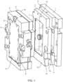
- Figure 1 shows an injection molding tool comprising a set of mold plates.
- Injection molding tools of this type is known in many different embodiments comprising two or more mold plates and with different functionality depending on e.g. the design of the product that is molded in the injection molding tool.
- the embodiment shown here is therefore only an example of the construction of such an injection molding tool where the mold plates comprises a clamping plate 1, a support plate 2, a runner/stripper plate 3, a runner channel plate 4 and a mold plate 5 forming one side of the mold cavity (the other side is not shown) in the drawings.
- the skilled person would easily recognize that the present invention may also be applied to injection molding tools having more or less mold plates with other functions than the mold plates shown in figure 1 .
- each mold plate 1, 2, 3, 4 and 5 have mutually opposite and parallel abutting side faces (14, 15, defining the thickness of the mold plate 1, 2, 3, 4, 5.
- Each of the mold plates 1, 2, 3, 4 and 5 according to figure 1 further comprises a mold insert 6, 7 which in this context covers any component that can be separated from the mold plate and especially components having a cavity or channel for leading the molten plastic material, such as an insert forming the mold cavity, the runner channels, the sprue or the like.
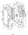
- the injection molding tool shown in figure 1 could be made in the conventional manner where each of the mold plates 1, 2, 3, 4 or 5 are made from a massive plate of steel, According to the present invention, however, one or more of the injection mold plates may be made from one or more connection plates connecting the guide bushings with the mold insert sockets and where the connection plates are thinner than the thickness of the injection mold plate.
- the mold plates 1, 2, 3, 4 are each advantageously made by additive manufacturing from especially a plastic or polymer material.
- Each mold plate1, 2, 3, 4 and 5 comprises two guide bushings 8, 9, 10, 11 and one guide bushing on one mold plate is aligned with a similar guide bushing on another mold plate, so that the mold plates can slide axially with respect to the other on a common guide pin (not shown).
- Each of the mold plates 1, 2, 3, 4 and 5 further comprises a mold insert socket 12, 13 for releasably insertion of a mold insert 6, 7.
- each of the mold plates 1, 2, 3, 4 and 5 comprises two connection plates 19, 20 interconnecting the guide bushings 8, 9, 10, 11 with the mold insert sockets 12, 13.
- the two connection plates 19, 20 on each injection mold plate 1, 2, 3, 4, 5 forms the mutually opposite and parallel abutting surfaces 14, 15 on that injection mold plate 1, 2, 3, 4, 5.
- connection plates 19, 20 are furthermore connected along their complete periphery by a peripheral flange 21 so that the connection plates 19, 20 forms a closed space together with the peripheral flange 21.
- a peripheral flange 21 so that the connection plates 19, 20 forms a closed space together with the peripheral flange 21.
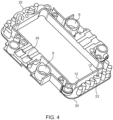
- Figure 4 shows a cross section through an alternative embodiment of a mold plate 5 according to figure 2 and 3 where the periphery of the connection plates are not interconnected by the peripheral flange 21 shown in figure 2 and 3 .
- a number of further reinforcing flanges 22 or rods 23 extends between the two connecting plates (only one shown in the drawing).
- this cross section shows other elements, such as channels 24 adapted for leading coolant to the mold insert 6 that can be produced by additive manufacturing.
Landscapes
- Engineering & Computer Science (AREA)
- Manufacturing & Machinery (AREA)
- Mechanical Engineering (AREA)
- Chemical & Material Sciences (AREA)
- Materials Engineering (AREA)
- Moulds For Moulding Plastics Or The Like (AREA)
Claims (13)
- Spritzgusswerkzeug, das dazu konfiguriert ist, in einer Spritzgusseinrichtung zum automatisierten Formen von Werkstücken aus Kunststoff montiert zu werden, wobei das Spritzgusswerkzeug in seiner geschlossenen Position mindestens zwei separate Formplatten (1, 2, 3, 4, 5) umfasst, die jeweils eine Formeinsatzfassung (12, 13) mit einem in der Formeinsatzfassung befestigten Formeinsatz (6, 7) aufweisen, und
wobei jede Formplatte einander gegenüberliegende und parallel anliegende Seitenflächen (14, 15) aufweist, welche die Dicke der Formplatte definieren, und die Formplatten weiter eine Anzahl miteinander ausgerichteter Führungsbuchsen (8, 9, 10, 11) umfassen, die Durchgangslöcher bilden, die zum axialen Gleiten einer der Formplatten in Bezug auf die andere auf einem gemeinsamen Führungsstift in einer Richtung senkrecht zu den anliegenden Seitenflächen der Formplatten angepasst sind, dadurch gekennzeichnet, dass die Führungsbuchsen und die Formeinsatzfassung von mindestens einer Formplatte über eine oder mehrere Verbindungsplatten (19, 20) miteinander verbunden sind, die sich jeweils parallel zu den anliegenden Seitenflächen erstrecken und eine Dicke von weniger als der Hälfte der Dicke der Formplatte aufweisen. - Spritzgusswerkzeug nach Anspruch 1, dadurch gekennzeichnet, dass die Durchgangslöcher und die Formeinsatzfassungen mindestens einer Formplatte über zwei zueinander beabstandete Verbindungsplatten miteinander verbunden sind.
- Spritzgusswerkzeug nach Anspruch 2, dadurch gekennzeichnet, dass jede der beiden zueinander beabstandeten Verbindungsplatten eine der einander gegenüberliegenden und parallel anliegenden Seitenflächen bildet.
- Spritzgusswerkzeug nach Anspruch 2, dadurch gekennzeichnet, dass sich die Formeinsatzfassung und die Führungsbuchsen zwischen den beiden Verbindungsplatten erstrecken.
- Spritzgusswerkzeug nach Anspruch 4, dadurch gekennzeichnet, dass sich eine Anzahl an Verstärkungsflanschen (22) oder -stäben (23) zwischen den beiden Verbindungsplatten erstreckt.
- Spritzgusswerkzeug nach einem der Ansprüche 2 bis 5, dadurch gekennzeichnet, dass die Außenumfänge der beiden zueinander beabstandeten Verbindungsplatten mindestens teilweise durch einen umlaufenden Flansch miteinander verbunden sind.
- Spritzgusswerkzeug nach Anspruch 6, dadurch gekennzeichnet, dass sich der umlaufende Flansch (21) senkrecht zu den einander gegenüberliegenden und parallel anliegenden Seitenflächen erstreckt.
- Spritzgusswerkzeug nach Anspruch 7, dadurch gekennzeichnet, dass die Formplatte einen geschlossenen Raum bildet, der sich zwischen den beiden zueinander beabstandeten Verbindungsplatten und dem umlaufenden Flansch erstreckt.
- Spritzgusswerkzeug nach einem oder mehreren der vorstehenden Ansprüche, dadurch gekennzeichnet, dass die Formplatte durch additive Fertigung als einzelne integrale Einheit hergestellt ist.
- Spritzgusswerkzeug nach Anspruch 9, dadurch gekennzeichnet, dass es aus einem Polymerwerkstoff gefertigt ist.
- Spritzgusswerkzeug nach Anspruch 8 und 10, dadurch gekennzeichnet, dass das zur additiven Fertigung der Formplatte verwendete Trägermaterial innerhalb des geschlossenen Raums belassen wird.
- Spritzgusswerkzeug nach Anspruch 10 oder 11, dadurch gekennzeichnet, dass der Formeinsatz aus einem metallischen Werkstoff, wie beispielsweise Stahl, gefertigt ist.
- Spritzgusswerkzeug nach Anspruch 10 oder 11, dadurch gekennzeichnet, dass die Führungsbuchsen jeweils eine Metallbuchse umfassen, die in einer Buchsenfassung montiert ist, die als integraler Bestandteil der additiv gefertigten Formplatte gebildet ist.
Applications Claiming Priority (2)
| Application Number | Priority Date | Filing Date | Title |
|---|---|---|---|
| DKPA202170107 | 2021-03-10 | ||
| PCT/EP2022/055960 WO2022189471A1 (en) | 2021-03-10 | 2022-03-09 | A mold tool for injection molding |
Publications (2)
| Publication Number | Publication Date |
|---|---|
| EP4304830A1 EP4304830A1 (de) | 2024-01-17 |
| EP4304830B1 true EP4304830B1 (de) | 2025-05-07 |
Family
ID=80928626
Family Applications (1)
| Application Number | Title | Priority Date | Filing Date |
|---|---|---|---|
| EP22711952.6A Active EP4304830B1 (de) | 2021-03-10 | 2022-03-09 | Formwerkzeug zum spritzgiessen |
Country Status (5)
| Country | Link |
|---|---|
| US (1) | US12275176B2 (de) |
| EP (1) | EP4304830B1 (de) |
| CN (1) | CN116940455B (de) |
| DK (1) | DK4304830T3 (de) |
| WO (1) | WO2022189471A1 (de) |
Family Cites Families (9)
| Publication number | Priority date | Publication date | Assignee | Title |
|---|---|---|---|---|
| JPS6012203B2 (ja) | 1980-03-31 | 1985-03-30 | 興國ゴム工業株式会社 | フラツシユレス金型装置 |
| FI82899C (fi) * | 1989-01-20 | 1991-05-10 | Mauno Montonen | Form. |
| US20080011417A1 (en) | 2006-07-11 | 2008-01-17 | Mark Manuel | Compound tooling for controlled work surface characteristics |
| AT513057A1 (de) * | 2012-06-21 | 2014-01-15 | Ifw Manfred Otte Gmbh | Formwerkzeug, insbesondere Spritzgießwerkzeug |
| EP3102391B1 (de) | 2015-02-03 | 2017-07-26 | Philips Lighting Holding B.V. | Durch fused deposition modeling hergestellte form zum formen und nachbilden von objekten, verfahren zu deren herstellung sowie fused deposition modeling 3d druckvorrichtung |
| EP3529025B1 (de) | 2016-10-18 | 2023-12-27 | Stratasys Ltd. | 3d-drucken einer struktur zum spritzgiessen |
| CN207643508U (zh) | 2017-11-06 | 2018-07-24 | 深圳市迪嘉机械有限公司 | 一种新型快速塑料模具 |
| GB2570926A (en) | 2018-02-12 | 2019-08-14 | Surface Generation Ltd | Mould tool, method of assembling a mould tool and method of manufacture using a mould tool |
| DE102018002628A1 (de) * | 2018-03-29 | 2019-10-02 | Emacos GmbH | Formwerkzeug sowie Verfahren zu seiner Herstellung |
-
2022
- 2022-03-09 DK DK22711952.6T patent/DK4304830T3/da active
- 2022-03-09 US US18/549,411 patent/US12275176B2/en active Active
- 2022-03-09 WO PCT/EP2022/055960 patent/WO2022189471A1/en not_active Ceased
- 2022-03-09 CN CN202280019588.8A patent/CN116940455B/zh active Active
- 2022-03-09 EP EP22711952.6A patent/EP4304830B1/de active Active
Also Published As
| Publication number | Publication date |
|---|---|
| WO2022189471A1 (en) | 2022-09-15 |
| US20240165864A1 (en) | 2024-05-23 |
| CN116940455A (zh) | 2023-10-24 |
| CN116940455B (zh) | 2025-10-28 |
| EP4304830A1 (de) | 2024-01-17 |
| DK4304830T3 (da) | 2025-08-18 |
| US12275176B2 (en) | 2025-04-15 |
Similar Documents
| Publication | Publication Date | Title |
|---|---|---|
| US8128394B2 (en) | Interchangeable mold tooling | |
| EP2651598B1 (de) | Zum einspannen einer turbinenschaufel eingerichtete einrichtung und turbinenschaufel | |
| KR101812814B1 (ko) | 타이어용 몰드 | |
| EP3444092A1 (de) | Form, verfahren zur herstellung einer formkomponente und verfahren zur bereitstellung einer form | |
| CA2205621C (en) | Modular injection mold assembly | |
| JP3320193B2 (ja) | 射出成形用カセット金型ホルダー | |
| US7300271B2 (en) | Injection mold insert block alignment system | |
| EP4304830B1 (de) | Formwerkzeug zum spritzgiessen | |
| KR102154467B1 (ko) | 조립구조를 갖는 세라믹 성형물 제조용 초경지그 금형 | |
| EP2735419A1 (de) | Feinzentrierungseinheit für den Werkzeug- und Formenbau, deren Verwendung in einer Formvorrichtung zum Formen von geformten Gegenständen und mit dieser ausgestattete Formvorrichtung zum Formen von geformten Gegenständen | |
| EP4100226B1 (de) | Lager für eine linearführungsschiene | |
| US8251690B2 (en) | Mold assembly including a fixing bolt and a screw bolt | |
| US6213753B1 (en) | Mold apparatus | |
| CN216267083U (zh) | 一种便于换模的橡胶硫化生产模具 | |
| WO2026076075A1 (en) | Sand casting hybrid tooling pattern plate including a plate and an insert formed from additive manufacturing | |
| EP4188667A1 (de) | Form zum spritzgiessen | |
| EP4217176B1 (de) | Formwerkzeug zum spritzgiessen | |
| EP1839838B1 (de) | Auswurfvorrichtung für eine Spritzgiessmaschine | |
| CN105437474A (zh) | 一种音箱模具结构 | |
| WO2018190123A1 (ja) | 金型の製造方法 | |
| KR101898068B1 (ko) | 프레스 성형장치 및 방법 | |
| JP2002205324A (ja) | 射出成形用金型 | |
| CZ309931B6 (cs) | Modulární vstřikovací forma | |
| JPS62227715A (ja) | 射出成形金型 | |
| CN116373221A (zh) | 模具组件、成形用模具以及成形物的成形方法 |
Legal Events
| Date | Code | Title | Description |
|---|---|---|---|
| STAA | Information on the status of an ep patent application or granted ep patent |
Free format text: STATUS: UNKNOWN |
|
| STAA | Information on the status of an ep patent application or granted ep patent |
Free format text: STATUS: THE INTERNATIONAL PUBLICATION HAS BEEN MADE |
|
| PUAI | Public reference made under article 153(3) epc to a published international application that has entered the european phase |
Free format text: ORIGINAL CODE: 0009012 |
|
| STAA | Information on the status of an ep patent application or granted ep patent |
Free format text: STATUS: REQUEST FOR EXAMINATION WAS MADE |
|
| 17P | Request for examination filed |
Effective date: 20231005 |
|
| AK | Designated contracting states |
Kind code of ref document: A1 Designated state(s): AL AT BE BG CH CY CZ DE DK EE ES FI FR GB GR HR HU IE IS IT LI LT LU LV MC MK MT NL NO PL PT RO RS SE SI SK SM TR |
|
| P01 | Opt-out of the competence of the unified patent court (upc) registered |
Effective date: 20240312 |
|
| DAV | Request for validation of the european patent (deleted) | ||
| DAX | Request for extension of the european patent (deleted) | ||
| GRAP | Despatch of communication of intention to grant a patent |
Free format text: ORIGINAL CODE: EPIDOSNIGR1 |
|
| STAA | Information on the status of an ep patent application or granted ep patent |
Free format text: STATUS: GRANT OF PATENT IS INTENDED |
|
| INTG | Intention to grant announced |
Effective date: 20241031 |
|
| GRAS | Grant fee paid |
Free format text: ORIGINAL CODE: EPIDOSNIGR3 |
|
| GRAA | (expected) grant |
Free format text: ORIGINAL CODE: 0009210 |
|
| STAA | Information on the status of an ep patent application or granted ep patent |
Free format text: STATUS: THE PATENT HAS BEEN GRANTED |
|
| AK | Designated contracting states |
Kind code of ref document: B1 Designated state(s): AL AT BE BG CH CY CZ DE DK EE ES FI FR GB GR HR HU IE IS IT LI LT LU LV MC MK MT NL NO PL PT RO RS SE SI SK SM TR |
|
| REG | Reference to a national code |
Ref country code: GB Ref legal event code: FG4D |
|
| REG | Reference to a national code |
Ref country code: CH Ref legal event code: EP |
|
| REG | Reference to a national code |
Ref country code: DE Ref legal event code: R096 Ref document number: 602022014264 Country of ref document: DE |
|
| REG | Reference to a national code |
Ref country code: IE Ref legal event code: FG4D |
|
| REG | Reference to a national code |
Ref country code: DK Ref legal event code: T3 Effective date: 20250808 |
|
| REG | Reference to a national code |
Ref country code: NL Ref legal event code: MP Effective date: 20250507 |
|
| PG25 | Lapsed in a contracting state [announced via postgrant information from national office to epo] |
Ref country code: FI Free format text: LAPSE BECAUSE OF FAILURE TO SUBMIT A TRANSLATION OF THE DESCRIPTION OR TO PAY THE FEE WITHIN THE PRESCRIBED TIME-LIMIT Effective date: 20250507 Ref country code: ES Free format text: LAPSE BECAUSE OF FAILURE TO SUBMIT A TRANSLATION OF THE DESCRIPTION OR TO PAY THE FEE WITHIN THE PRESCRIBED TIME-LIMIT Effective date: 20250507 Ref country code: PT Free format text: LAPSE BECAUSE OF FAILURE TO SUBMIT A TRANSLATION OF THE DESCRIPTION OR TO PAY THE FEE WITHIN THE PRESCRIBED TIME-LIMIT Effective date: 20250908 |
|
| REG | Reference to a national code |
Ref country code: LT Ref legal event code: MG9D |
|
| PG25 | Lapsed in a contracting state [announced via postgrant information from national office to epo] |
Ref country code: GR Free format text: LAPSE BECAUSE OF FAILURE TO SUBMIT A TRANSLATION OF THE DESCRIPTION OR TO PAY THE FEE WITHIN THE PRESCRIBED TIME-LIMIT Effective date: 20250808 Ref country code: NO Free format text: LAPSE BECAUSE OF FAILURE TO SUBMIT A TRANSLATION OF THE DESCRIPTION OR TO PAY THE FEE WITHIN THE PRESCRIBED TIME-LIMIT Effective date: 20250807 |
|
| PG25 | Lapsed in a contracting state [announced via postgrant information from national office to epo] |
Ref country code: PL Free format text: LAPSE BECAUSE OF FAILURE TO SUBMIT A TRANSLATION OF THE DESCRIPTION OR TO PAY THE FEE WITHIN THE PRESCRIBED TIME-LIMIT Effective date: 20250507 Ref country code: NL Free format text: LAPSE BECAUSE OF FAILURE TO SUBMIT A TRANSLATION OF THE DESCRIPTION OR TO PAY THE FEE WITHIN THE PRESCRIBED TIME-LIMIT Effective date: 20250507 |
|
| REG | Reference to a national code |
Ref country code: AT Ref legal event code: MK05 Ref document number: 1791998 Country of ref document: AT Kind code of ref document: T Effective date: 20250507 |
|
| PG25 | Lapsed in a contracting state [announced via postgrant information from national office to epo] |
Ref country code: BG Free format text: LAPSE BECAUSE OF FAILURE TO SUBMIT A TRANSLATION OF THE DESCRIPTION OR TO PAY THE FEE WITHIN THE PRESCRIBED TIME-LIMIT Effective date: 20250507 |
|
| PG25 | Lapsed in a contracting state [announced via postgrant information from national office to epo] |
Ref country code: HR Free format text: LAPSE BECAUSE OF FAILURE TO SUBMIT A TRANSLATION OF THE DESCRIPTION OR TO PAY THE FEE WITHIN THE PRESCRIBED TIME-LIMIT Effective date: 20250507 |
|
| PG25 | Lapsed in a contracting state [announced via postgrant information from national office to epo] |
Ref country code: AT Free format text: LAPSE BECAUSE OF FAILURE TO SUBMIT A TRANSLATION OF THE DESCRIPTION OR TO PAY THE FEE WITHIN THE PRESCRIBED TIME-LIMIT Effective date: 20250507 |
|
| PG25 | Lapsed in a contracting state [announced via postgrant information from national office to epo] |
Ref country code: RS Free format text: LAPSE BECAUSE OF FAILURE TO SUBMIT A TRANSLATION OF THE DESCRIPTION OR TO PAY THE FEE WITHIN THE PRESCRIBED TIME-LIMIT Effective date: 20250807 |
|
| PG25 | Lapsed in a contracting state [announced via postgrant information from national office to epo] |
Ref country code: IS Free format text: LAPSE BECAUSE OF FAILURE TO SUBMIT A TRANSLATION OF THE DESCRIPTION OR TO PAY THE FEE WITHIN THE PRESCRIBED TIME-LIMIT Effective date: 20250907 |
|
| PG25 | Lapsed in a contracting state [announced via postgrant information from national office to epo] |
Ref country code: LV Free format text: LAPSE BECAUSE OF FAILURE TO SUBMIT A TRANSLATION OF THE DESCRIPTION OR TO PAY THE FEE WITHIN THE PRESCRIBED TIME-LIMIT Effective date: 20250507 |
|
| PG25 | Lapsed in a contracting state [announced via postgrant information from national office to epo] |
Ref country code: SM Free format text: LAPSE BECAUSE OF FAILURE TO SUBMIT A TRANSLATION OF THE DESCRIPTION OR TO PAY THE FEE WITHIN THE PRESCRIBED TIME-LIMIT Effective date: 20250507 |
|
| PG25 | Lapsed in a contracting state [announced via postgrant information from national office to epo] |
Ref country code: CZ Free format text: LAPSE BECAUSE OF FAILURE TO SUBMIT A TRANSLATION OF THE DESCRIPTION OR TO PAY THE FEE WITHIN THE PRESCRIBED TIME-LIMIT Effective date: 20250507 |
|
| PG25 | Lapsed in a contracting state [announced via postgrant information from national office to epo] |
Ref country code: EE Free format text: LAPSE BECAUSE OF FAILURE TO SUBMIT A TRANSLATION OF THE DESCRIPTION OR TO PAY THE FEE WITHIN THE PRESCRIBED TIME-LIMIT Effective date: 20250507 |
|
| PG25 | Lapsed in a contracting state [announced via postgrant information from national office to epo] |
Ref country code: SK Free format text: LAPSE BECAUSE OF FAILURE TO SUBMIT A TRANSLATION OF THE DESCRIPTION OR TO PAY THE FEE WITHIN THE PRESCRIBED TIME-LIMIT Effective date: 20250507 |
|
| PG25 | Lapsed in a contracting state [announced via postgrant information from national office to epo] |
Ref country code: IT Free format text: LAPSE BECAUSE OF FAILURE TO SUBMIT A TRANSLATION OF THE DESCRIPTION OR TO PAY THE FEE WITHIN THE PRESCRIBED TIME-LIMIT Effective date: 20250507 |
|
| REG | Reference to a national code |
Ref country code: DE Ref legal event code: R097 Ref document number: 602022014264 Country of ref document: DE |
|
| PLBE | No opposition filed within time limit |
Free format text: ORIGINAL CODE: 0009261 |
|
| STAA | Information on the status of an ep patent application or granted ep patent |
Free format text: STATUS: NO OPPOSITION FILED WITHIN TIME LIMIT |
|
| REG | Reference to a national code |
Ref country code: CH Ref legal event code: L10 Free format text: ST27 STATUS EVENT CODE: U-0-0-L10-L00 (AS PROVIDED BY THE NATIONAL OFFICE) Effective date: 20260318 |
|
| PGFP | Annual fee paid to national office [announced via postgrant information from national office to epo] |
Ref country code: GB Payment date: 20260324 Year of fee payment: 5 |
|
| PGFP | Annual fee paid to national office [announced via postgrant information from national office to epo] |
Ref country code: DK Payment date: 20260324 Year of fee payment: 5 Ref country code: DE Payment date: 20260319 Year of fee payment: 5 |
|
| 26N | No opposition filed |
Effective date: 20260210 |