EP4300524A1 - Stromspeicherelement - Google Patents
Stromspeicherelement Download PDFInfo
- Publication number
- EP4300524A1 EP4300524A1 EP22780854.0A EP22780854A EP4300524A1 EP 4300524 A1 EP4300524 A1 EP 4300524A1 EP 22780854 A EP22780854 A EP 22780854A EP 4300524 A1 EP4300524 A1 EP 4300524A1
- Authority
- EP
- European Patent Office
- Prior art keywords
- energy storage
- electrode assembly
- storage device
- mpa
- less
- Prior art date
- Legal status (The legal status is an assumption and is not a legal conclusion. Google has not performed a legal analysis and makes no representation as to the accuracy of the status listed.)
- Pending
Links
- 238000003860 storage Methods 0.000 title description 3
- 230000005611 electricity Effects 0.000 title 1
- 238000004146 energy storage Methods 0.000 claims abstract description 128
- 239000008151 electrolyte solution Substances 0.000 claims abstract description 29
- 239000010410 layer Substances 0.000 claims description 48
- 239000000758 substrate Substances 0.000 claims description 42
- 239000002245 particle Substances 0.000 claims description 24
- 239000011230 binding agent Substances 0.000 claims description 21
- 239000011247 coating layer Substances 0.000 claims description 10
- 230000035699 permeability Effects 0.000 claims description 9
- 229940021013 electrolyte solution Drugs 0.000 description 51
- 230000007423 decrease Effects 0.000 description 33
- 239000007774 positive electrode material Substances 0.000 description 32
- 239000007773 negative electrode material Substances 0.000 description 30
- 239000011255 nonaqueous electrolyte Substances 0.000 description 30
- OKTJSMMVPCPJKN-UHFFFAOYSA-N Carbon Chemical compound [C] OKTJSMMVPCPJKN-UHFFFAOYSA-N 0.000 description 29
- 239000000463 material Substances 0.000 description 29
- 239000004698 Polyethylene Substances 0.000 description 19
- 238000000034 method Methods 0.000 description 18
- -1 polytetrafluoroethylene Polymers 0.000 description 17
- 239000006258 conductive agent Substances 0.000 description 15
- 239000004743 Polypropylene Substances 0.000 description 13
- 230000000052 comparative effect Effects 0.000 description 13
- 229910052751 metal Inorganic materials 0.000 description 13
- 239000002184 metal Substances 0.000 description 13
- 239000003575 carbonaceous material Substances 0.000 description 12
- 239000002131 composite material Substances 0.000 description 12
- 239000011888 foil Substances 0.000 description 12
- 229910052782 aluminium Inorganic materials 0.000 description 11
- 230000014759 maintenance of location Effects 0.000 description 11
- 239000002904 solvent Substances 0.000 description 11
- 229910052799 carbon Inorganic materials 0.000 description 10
- PXHVJJICTQNCMI-UHFFFAOYSA-N nickel Substances [Ni] PXHVJJICTQNCMI-UHFFFAOYSA-N 0.000 description 10
- 230000000452 restraining effect Effects 0.000 description 10
- HBBGRARXTFLTSG-UHFFFAOYSA-N Lithium ion Chemical compound [Li+] HBBGRARXTFLTSG-UHFFFAOYSA-N 0.000 description 9
- XAGFODPZIPBFFR-UHFFFAOYSA-N aluminium Chemical compound [Al] XAGFODPZIPBFFR-UHFFFAOYSA-N 0.000 description 9
- 230000006835 compression Effects 0.000 description 9
- 238000007906 compression Methods 0.000 description 9
- 239000003792 electrolyte Substances 0.000 description 9
- 229910001416 lithium ion Inorganic materials 0.000 description 9
- 229920005989 resin Polymers 0.000 description 9
- 239000011347 resin Substances 0.000 description 9
- 150000003839 salts Chemical class 0.000 description 9
- 239000002562 thickening agent Substances 0.000 description 9
- RYGMFSIKBFXOCR-UHFFFAOYSA-N Copper Chemical compound [Cu] RYGMFSIKBFXOCR-UHFFFAOYSA-N 0.000 description 8
- 239000002033 PVDF binder Substances 0.000 description 8
- 239000006230 acetylene black Substances 0.000 description 8
- 239000011149 active material Substances 0.000 description 8
- 150000005676 cyclic carbonates Chemical class 0.000 description 8
- 229920002981 polyvinylidene fluoride Polymers 0.000 description 8
- 150000005678 chain carbonates Chemical class 0.000 description 7
- 239000013078 crystal Substances 0.000 description 7
- 239000000945 filler Substances 0.000 description 7
- 229910002804 graphite Inorganic materials 0.000 description 7
- 239000010439 graphite Substances 0.000 description 7
- 239000003990 capacitor Substances 0.000 description 6
- 239000011889 copper foil Substances 0.000 description 6
- 229910021469 graphitizable carbon Inorganic materials 0.000 description 6
- 229910003002 lithium salt Inorganic materials 0.000 description 6
- 159000000002 lithium salts Chemical class 0.000 description 6
- 238000004519 manufacturing process Methods 0.000 description 6
- 239000010936 titanium Substances 0.000 description 6
- 229910052723 transition metal Inorganic materials 0.000 description 6
- 229920002134 Carboxymethyl cellulose Polymers 0.000 description 5
- KMTRUDSVKNLOMY-UHFFFAOYSA-N Ethylene carbonate Chemical compound O=C1OCCO1 KMTRUDSVKNLOMY-UHFFFAOYSA-N 0.000 description 5
- VYPSYNLAJGMNEJ-UHFFFAOYSA-N Silicium dioxide Chemical compound O=[Si]=O VYPSYNLAJGMNEJ-UHFFFAOYSA-N 0.000 description 5
- 239000000654 additive Substances 0.000 description 5
- 150000001875 compounds Chemical class 0.000 description 5
- HNPSIPDUKPIQMN-UHFFFAOYSA-N dioxosilane;oxo(oxoalumanyloxy)alumane Chemical compound O=[Si]=O.O=[Al]O[Al]=O HNPSIPDUKPIQMN-UHFFFAOYSA-N 0.000 description 5
- JBTWLSYIZRCDFO-UHFFFAOYSA-N ethyl methyl carbonate Chemical compound CCOC(=O)OC JBTWLSYIZRCDFO-UHFFFAOYSA-N 0.000 description 5
- 150000002484 inorganic compounds Chemical class 0.000 description 5
- 229910010272 inorganic material Inorganic materials 0.000 description 5
- 239000000203 mixture Substances 0.000 description 5
- 229920000573 polyethylene Polymers 0.000 description 5
- 238000002360 preparation method Methods 0.000 description 5
- RUOJZAUFBMNUDX-UHFFFAOYSA-N propylene carbonate Chemical compound CC1COC(=O)O1 RUOJZAUFBMNUDX-UHFFFAOYSA-N 0.000 description 5
- 229920003048 styrene butadiene rubber Polymers 0.000 description 5
- 229910052719 titanium Inorganic materials 0.000 description 5
- VTYYLEPIZMXCLO-UHFFFAOYSA-L Calcium carbonate Chemical compound [Ca+2].[O-]C([O-])=O VTYYLEPIZMXCLO-UHFFFAOYSA-L 0.000 description 4
- 229910001290 LiPF6 Inorganic materials 0.000 description 4
- SECXISVLQFMRJM-UHFFFAOYSA-N N-Methylpyrrolidone Chemical compound CN1CCCC1=O SECXISVLQFMRJM-UHFFFAOYSA-N 0.000 description 4
- GWEVSGVZZGPLCZ-UHFFFAOYSA-N Titan oxide Chemical compound O=[Ti]=O GWEVSGVZZGPLCZ-UHFFFAOYSA-N 0.000 description 4
- RTAQQCXQSZGOHL-UHFFFAOYSA-N Titanium Chemical compound [Ti] RTAQQCXQSZGOHL-UHFFFAOYSA-N 0.000 description 4
- 230000000996 additive effect Effects 0.000 description 4
- 229910045601 alloy Inorganic materials 0.000 description 4
- 239000000956 alloy Substances 0.000 description 4
- QVQLCTNNEUAWMS-UHFFFAOYSA-N barium oxide Chemical compound [Ba]=O QVQLCTNNEUAWMS-UHFFFAOYSA-N 0.000 description 4
- TZCXTZWJZNENPQ-UHFFFAOYSA-L barium sulfate Chemical compound [Ba+2].[O-]S([O-])(=O)=O TZCXTZWJZNENPQ-UHFFFAOYSA-L 0.000 description 4
- 239000006229 carbon black Substances 0.000 description 4
- 239000000470 constituent Substances 0.000 description 4
- 229910052802 copper Inorganic materials 0.000 description 4
- 239000010949 copper Substances 0.000 description 4
- 239000002612 dispersion medium Substances 0.000 description 4
- 230000000694 effects Effects 0.000 description 4
- 239000010954 inorganic particle Substances 0.000 description 4
- 230000010220 ion permeability Effects 0.000 description 4
- 229910052744 lithium Inorganic materials 0.000 description 4
- 238000005259 measurement Methods 0.000 description 4
- 239000002905 metal composite material Substances 0.000 description 4
- 150000002739 metals Chemical class 0.000 description 4
- 229920001155 polypropylene Polymers 0.000 description 4
- 239000000843 powder Substances 0.000 description 4
- 238000003825 pressing Methods 0.000 description 4
- 239000007787 solid Substances 0.000 description 4
- IATRAKWUXMZMIY-UHFFFAOYSA-N strontium oxide Chemical compound [O-2].[Sr+2] IATRAKWUXMZMIY-UHFFFAOYSA-N 0.000 description 4
- 239000000126 substance Substances 0.000 description 4
- 238000012360 testing method Methods 0.000 description 4
- 229910052718 tin Inorganic materials 0.000 description 4
- 239000011800 void material Substances 0.000 description 4
- VAYTZRYEBVHVLE-UHFFFAOYSA-N 1,3-dioxol-2-one Chemical compound O=C1OC=CO1 VAYTZRYEBVHVLE-UHFFFAOYSA-N 0.000 description 3
- 229910000838 Al alloy Inorganic materials 0.000 description 3
- 229910000323 aluminium silicate Inorganic materials 0.000 description 3
- 238000004891 communication Methods 0.000 description 3
- 238000007599 discharging Methods 0.000 description 3
- 229910021389 graphene Inorganic materials 0.000 description 3
- VLKZOEOYAKHREP-UHFFFAOYSA-N n-Hexane Chemical compound CCCCCC VLKZOEOYAKHREP-UHFFFAOYSA-N 0.000 description 3
- 229910052759 nickel Inorganic materials 0.000 description 3
- 229920000447 polyanionic polymer Polymers 0.000 description 3
- 229920000098 polyolefin Polymers 0.000 description 3
- 229910052710 silicon Inorganic materials 0.000 description 3
- 229910052814 silicon oxide Inorganic materials 0.000 description 3
- XLYOFNOQVPJJNP-UHFFFAOYSA-N water Substances O XLYOFNOQVPJJNP-UHFFFAOYSA-N 0.000 description 3
- ZZXUZKXVROWEIF-UHFFFAOYSA-N 1,2-butylene carbonate Chemical compound CCC1COC(=O)O1 ZZXUZKXVROWEIF-UHFFFAOYSA-N 0.000 description 2
- ZPFAVCIQZKRBGF-UHFFFAOYSA-N 1,3,2-dioxathiolane 2,2-dioxide Chemical compound O=S1(=O)OCCO1 ZPFAVCIQZKRBGF-UHFFFAOYSA-N 0.000 description 2
- YJTKZCDBKVTVBY-UHFFFAOYSA-N 1,3-Diphenylbenzene Chemical group C1=CC=CC=C1C1=CC=CC(C=2C=CC=CC=2)=C1 YJTKZCDBKVTVBY-UHFFFAOYSA-N 0.000 description 2
- DSMUTQTWFHVVGQ-UHFFFAOYSA-N 4,5-difluoro-1,3-dioxolan-2-one Chemical compound FC1OC(=O)OC1F DSMUTQTWFHVVGQ-UHFFFAOYSA-N 0.000 description 2
- BJWMSGRKJIOCNR-UHFFFAOYSA-N 4-ethenyl-1,3-dioxolan-2-one Chemical compound C=CC1COC(=O)O1 BJWMSGRKJIOCNR-UHFFFAOYSA-N 0.000 description 2
- SBLRHMKNNHXPHG-UHFFFAOYSA-N 4-fluoro-1,3-dioxolan-2-one Chemical compound FC1COC(=O)O1 SBLRHMKNNHXPHG-UHFFFAOYSA-N 0.000 description 2
- 239000005995 Aluminium silicate Substances 0.000 description 2
- BTBUEUYNUDRHOZ-UHFFFAOYSA-N Borate Chemical compound [O-]B([O-])[O-] BTBUEUYNUDRHOZ-UHFFFAOYSA-N 0.000 description 2
- 229910000881 Cu alloy Inorganic materials 0.000 description 2
- OIFBSDVPJOWBCH-UHFFFAOYSA-N Diethyl carbonate Chemical compound CCOC(=O)OCC OIFBSDVPJOWBCH-UHFFFAOYSA-N 0.000 description 2
- IAZDPXIOMUYVGZ-UHFFFAOYSA-N Dimethylsulphoxide Chemical compound CS(C)=O IAZDPXIOMUYVGZ-UHFFFAOYSA-N 0.000 description 2
- GUUVPOWQJOLRAS-UHFFFAOYSA-N Diphenyl disulfide Chemical compound C=1C=CC=CC=1SSC1=CC=CC=C1 GUUVPOWQJOLRAS-UHFFFAOYSA-N 0.000 description 2
- 229920002943 EPDM rubber Polymers 0.000 description 2
- UQSXHKLRYXJYBZ-UHFFFAOYSA-N Iron oxide Chemical compound [Fe]=O UQSXHKLRYXJYBZ-UHFFFAOYSA-N 0.000 description 2
- 229910011328 LiNi0.6Co0.2Mn0.2O2 Inorganic materials 0.000 description 2
- WHXSMMKQMYFTQS-UHFFFAOYSA-N Lithium Chemical compound [Li] WHXSMMKQMYFTQS-UHFFFAOYSA-N 0.000 description 2
- 239000004642 Polyimide Substances 0.000 description 2
- 241000156302 Porcine hemagglutinating encephalomyelitis virus Species 0.000 description 2
- 229910052581 Si3N4 Inorganic materials 0.000 description 2
- 239000002174 Styrene-butadiene Substances 0.000 description 2
- 238000002441 X-ray diffraction Methods 0.000 description 2
- 229910021536 Zeolite Inorganic materials 0.000 description 2
- 235000012211 aluminium silicate Nutrition 0.000 description 2
- 229910052586 apatite Inorganic materials 0.000 description 2
- 150000001491 aromatic compounds Chemical class 0.000 description 2
- 229910021383 artificial graphite Inorganic materials 0.000 description 2
- 125000004429 atom Chemical group 0.000 description 2
- 229910052788 barium Inorganic materials 0.000 description 2
- OYLGJCQECKOTOL-UHFFFAOYSA-L barium fluoride Chemical compound [F-].[F-].[Ba+2] OYLGJCQECKOTOL-UHFFFAOYSA-L 0.000 description 2
- 229910001632 barium fluoride Inorganic materials 0.000 description 2
- 239000000440 bentonite Substances 0.000 description 2
- 229910000278 bentonite Inorganic materials 0.000 description 2
- SVPXDRXYRYOSEX-UHFFFAOYSA-N bentoquatam Chemical compound O.O=[Si]=O.O=[Al]O[Al]=O SVPXDRXYRYOSEX-UHFFFAOYSA-N 0.000 description 2
- 229910001593 boehmite Inorganic materials 0.000 description 2
- 229910052796 boron Inorganic materials 0.000 description 2
- 229910052794 bromium Inorganic materials 0.000 description 2
- 239000011575 calcium Substances 0.000 description 2
- 229910052791 calcium Inorganic materials 0.000 description 2
- 229910000019 calcium carbonate Inorganic materials 0.000 description 2
- WUKWITHWXAAZEY-UHFFFAOYSA-L calcium difluoride Chemical compound [F-].[F-].[Ca+2] WUKWITHWXAAZEY-UHFFFAOYSA-L 0.000 description 2
- 229910001634 calcium fluoride Inorganic materials 0.000 description 2
- BRPQOXSCLDDYGP-UHFFFAOYSA-N calcium oxide Chemical compound [O-2].[Ca+2] BRPQOXSCLDDYGP-UHFFFAOYSA-N 0.000 description 2
- 239000000292 calcium oxide Substances 0.000 description 2
- ODINCKMPIJJUCX-UHFFFAOYSA-N calcium oxide Inorganic materials [Ca]=O ODINCKMPIJJUCX-UHFFFAOYSA-N 0.000 description 2
- 150000004649 carbonic acid derivatives Chemical class 0.000 description 2
- 239000001768 carboxy methyl cellulose Substances 0.000 description 2
- 235000010948 carboxy methyl cellulose Nutrition 0.000 description 2
- 239000008112 carboxymethyl-cellulose Substances 0.000 description 2
- 150000004770 chalcogenides Chemical class 0.000 description 2
- 229910052801 chlorine Inorganic materials 0.000 description 2
- 229910052804 chromium Inorganic materials 0.000 description 2
- PMHQVHHXPFUNSP-UHFFFAOYSA-M copper(1+);methylsulfanylmethane;bromide Chemical compound Br[Cu].CSC PMHQVHHXPFUNSP-UHFFFAOYSA-M 0.000 description 2
- GUJOJGAPFQRJSV-UHFFFAOYSA-N dialuminum;dioxosilane;oxygen(2-);hydrate Chemical compound O.[O-2].[O-2].[O-2].[Al+3].[Al+3].O=[Si]=O.O=[Si]=O.O=[Si]=O.O=[Si]=O GUJOJGAPFQRJSV-UHFFFAOYSA-N 0.000 description 2
- TXCDCPKCNAJMEE-UHFFFAOYSA-N dibenzofuran Chemical compound C1=CC=C2C3=CC=CC=C3OC2=C1 TXCDCPKCNAJMEE-UHFFFAOYSA-N 0.000 description 2
- QXYJCZRRLLQGCR-UHFFFAOYSA-N dioxomolybdenum Chemical compound O=[Mo]=O QXYJCZRRLLQGCR-UHFFFAOYSA-N 0.000 description 2
- KZHJGOXRZJKJNY-UHFFFAOYSA-N dioxosilane;oxo(oxoalumanyloxy)alumane Chemical compound O=[Si]=O.O=[Si]=O.O=[Al]O[Al]=O.O=[Al]O[Al]=O.O=[Al]O[Al]=O KZHJGOXRZJKJNY-UHFFFAOYSA-N 0.000 description 2
- ZUOUZKKEUPVFJK-UHFFFAOYSA-N diphenyl Chemical compound C1=CC=CC=C1C1=CC=CC=C1 ZUOUZKKEUPVFJK-UHFFFAOYSA-N 0.000 description 2
- USIUVYZYUHIAEV-UHFFFAOYSA-N diphenyl ether Chemical compound C=1C=CC=CC=1OC1=CC=CC=C1 USIUVYZYUHIAEV-UHFFFAOYSA-N 0.000 description 2
- 238000009826 distribution Methods 0.000 description 2
- 229910052731 fluorine Inorganic materials 0.000 description 2
- 125000000524 functional group Chemical group 0.000 description 2
- 229910052733 gallium Inorganic materials 0.000 description 2
- 239000007789 gas Substances 0.000 description 2
- 229910052732 germanium Inorganic materials 0.000 description 2
- 150000004676 glycans Chemical class 0.000 description 2
- FAHBNUUHRFUEAI-UHFFFAOYSA-M hydroxidooxidoaluminium Chemical compound O[Al]=O FAHBNUUHRFUEAI-UHFFFAOYSA-M 0.000 description 2
- 238000002347 injection Methods 0.000 description 2
- 239000007924 injection Substances 0.000 description 2
- 229910052500 inorganic mineral Inorganic materials 0.000 description 2
- 229910052742 iron Inorganic materials 0.000 description 2
- XEEYBQQBJWHFJM-UHFFFAOYSA-N iron Substances [Fe] XEEYBQQBJWHFJM-UHFFFAOYSA-N 0.000 description 2
- NLYAJNPCOHFWQQ-UHFFFAOYSA-N kaolin Chemical compound O.O.O=[Al]O[Si](=O)O[Si](=O)O[Al]=O NLYAJNPCOHFWQQ-UHFFFAOYSA-N 0.000 description 2
- 239000011777 magnesium Substances 0.000 description 2
- 229910052749 magnesium Inorganic materials 0.000 description 2
- 239000000395 magnesium oxide Substances 0.000 description 2
- CPLXHLVBOLITMK-UHFFFAOYSA-N magnesium oxide Inorganic materials [Mg]=O CPLXHLVBOLITMK-UHFFFAOYSA-N 0.000 description 2
- AXZKOIWUVFPNLO-UHFFFAOYSA-N magnesium;oxygen(2-) Chemical compound [O-2].[Mg+2] AXZKOIWUVFPNLO-UHFFFAOYSA-N 0.000 description 2
- 229910052748 manganese Inorganic materials 0.000 description 2
- 229910052752 metalloid Inorganic materials 0.000 description 2
- 150000002738 metalloids Chemical class 0.000 description 2
- 239000010445 mica Substances 0.000 description 2
- 229910052618 mica group Inorganic materials 0.000 description 2
- 239000011707 mineral Substances 0.000 description 2
- 238000002156 mixing Methods 0.000 description 2
- 229910052750 molybdenum Inorganic materials 0.000 description 2
- 229910052901 montmorillonite Inorganic materials 0.000 description 2
- 229910052863 mullite Inorganic materials 0.000 description 2
- 229910052758 niobium Inorganic materials 0.000 description 2
- 150000004767 nitrides Chemical class 0.000 description 2
- 229910052757 nitrogen Inorganic materials 0.000 description 2
- 229910052755 nonmetal Inorganic materials 0.000 description 2
- 239000004745 nonwoven fabric Substances 0.000 description 2
- 239000010450 olivine Substances 0.000 description 2
- 229910052609 olivine Inorganic materials 0.000 description 2
- TWNQGVIAIRXVLR-UHFFFAOYSA-N oxo(oxoalumanyloxy)alumane Chemical compound O=[Al]O[Al]=O TWNQGVIAIRXVLR-UHFFFAOYSA-N 0.000 description 2
- VSIIXMUUUJUKCM-UHFFFAOYSA-D pentacalcium;fluoride;triphosphate Chemical compound [F-].[Ca+2].[Ca+2].[Ca+2].[Ca+2].[Ca+2].[O-]P([O-])([O-])=O.[O-]P([O-])([O-])=O.[O-]P([O-])([O-])=O VSIIXMUUUJUKCM-UHFFFAOYSA-D 0.000 description 2
- 239000002006 petroleum coke Substances 0.000 description 2
- 239000011301 petroleum pitch Substances 0.000 description 2
- 229910052698 phosphorus Inorganic materials 0.000 description 2
- 229920001721 polyimide Polymers 0.000 description 2
- 229920000642 polymer Polymers 0.000 description 2
- 229920000137 polyphosphoric acid Polymers 0.000 description 2
- 229920001282 polysaccharide Polymers 0.000 description 2
- 239000005017 polysaccharide Substances 0.000 description 2
- 229920001343 polytetrafluoroethylene Polymers 0.000 description 2
- 239000004810 polytetrafluoroethylene Substances 0.000 description 2
- 239000011148 porous material Substances 0.000 description 2
- 229910052700 potassium Inorganic materials 0.000 description 2
- 229910052706 scandium Inorganic materials 0.000 description 2
- HQVNEWCFYHHQES-UHFFFAOYSA-N silicon nitride Chemical compound N12[Si]34N5[Si]62N3[Si]51N64 HQVNEWCFYHHQES-UHFFFAOYSA-N 0.000 description 2
- 239000011734 sodium Substances 0.000 description 2
- 229910052708 sodium Inorganic materials 0.000 description 2
- 239000011029 spinel Substances 0.000 description 2
- 229910052596 spinel Inorganic materials 0.000 description 2
- 229910001220 stainless steel Inorganic materials 0.000 description 2
- 239000010935 stainless steel Substances 0.000 description 2
- 229910052712 strontium Inorganic materials 0.000 description 2
- HHVIBTZHLRERCL-UHFFFAOYSA-N sulfonyldimethane Chemical compound CS(C)(=O)=O HHVIBTZHLRERCL-UHFFFAOYSA-N 0.000 description 2
- 239000000454 talc Substances 0.000 description 2
- 229910052623 talc Inorganic materials 0.000 description 2
- 229910052715 tantalum Inorganic materials 0.000 description 2
- YTZKOQUCBOVLHL-UHFFFAOYSA-N tert-butylbenzene Chemical compound CC(C)(C)C1=CC=CC=C1 YTZKOQUCBOVLHL-UHFFFAOYSA-N 0.000 description 2
- RBYFNZOIUUXJQD-UHFFFAOYSA-J tetralithium oxalate Chemical compound [Li+].[Li+].[Li+].[Li+].[O-]C(=O)C([O-])=O.[O-]C(=O)C([O-])=O RBYFNZOIUUXJQD-UHFFFAOYSA-J 0.000 description 2
- 239000004408 titanium dioxide Substances 0.000 description 2
- 229910052720 vanadium Inorganic materials 0.000 description 2
- 239000010457 zeolite Substances 0.000 description 2
- 229910052725 zinc Inorganic materials 0.000 description 2
- 229910052726 zirconium Inorganic materials 0.000 description 2
- VSKCGJBMHRNFCZ-UHFFFAOYSA-N (2,2-dioxo-1,3,2-dioxathiolan-4-yl)methyl methanesulfonate Chemical compound CS(=O)(=O)OCC1COS(=O)(=O)O1 VSKCGJBMHRNFCZ-UHFFFAOYSA-N 0.000 description 1
- WDXYVJKNSMILOQ-UHFFFAOYSA-N 1,3,2-dioxathiolane 2-oxide Chemical compound O=S1OCCO1 WDXYVJKNSMILOQ-UHFFFAOYSA-N 0.000 description 1
- FSSPGSAQUIYDCN-UHFFFAOYSA-N 1,3-Propane sultone Chemical compound O=S1(=O)CCCO1 FSSPGSAQUIYDCN-UHFFFAOYSA-N 0.000 description 1
- IOBWAHRFIPQEQL-UHFFFAOYSA-N 1,3-difluoro-2-methoxybenzene Chemical compound COC1=C(F)C=CC=C1F IOBWAHRFIPQEQL-UHFFFAOYSA-N 0.000 description 1
- OTGQPYSISUUHAF-UHFFFAOYSA-N 1,3-difluoro-5-methoxybenzene Chemical compound COC1=CC(F)=CC(F)=C1 OTGQPYSISUUHAF-UHFFFAOYSA-N 0.000 description 1
- HUDMAQLYMUKZOZ-UHFFFAOYSA-N 1,4-difluoro-2-methoxybenzene Chemical compound COC1=CC(F)=CC=C1F HUDMAQLYMUKZOZ-UHFFFAOYSA-N 0.000 description 1
- GUYHXQLLIISBQF-UHFFFAOYSA-N 1-cyclohexyl-2-fluorobenzene Chemical compound FC1=CC=CC=C1C1CCCCC1 GUYHXQLLIISBQF-UHFFFAOYSA-N 0.000 description 1
- YAOIFBJJGFYYFI-UHFFFAOYSA-N 1-cyclohexyl-4-fluorobenzene Chemical compound C1=CC(F)=CC=C1C1CCCCC1 YAOIFBJJGFYYFI-UHFFFAOYSA-N 0.000 description 1
- MBDUIEKYVPVZJH-UHFFFAOYSA-N 1-ethylsulfonylethane Chemical compound CCS(=O)(=O)CC MBDUIEKYVPVZJH-UHFFFAOYSA-N 0.000 description 1
- KLECYOQFQXJYBC-UHFFFAOYSA-N 1-fluoro-2-phenylbenzene Chemical group FC1=CC=CC=C1C1=CC=CC=C1 KLECYOQFQXJYBC-UHFFFAOYSA-N 0.000 description 1
- CRMJLJFDPNJIQA-UHFFFAOYSA-N 2,4-difluoro-1-methoxybenzene Chemical compound COC1=CC=C(F)C=C1F CRMJLJFDPNJIQA-UHFFFAOYSA-N 0.000 description 1
- FALRKNHUBBKYCC-UHFFFAOYSA-N 2-(chloromethyl)pyridine-3-carbonitrile Chemical compound ClCC1=NC=CC=C1C#N FALRKNHUBBKYCC-UHFFFAOYSA-N 0.000 description 1
- QHTJSSMHBLGUHV-UHFFFAOYSA-N 2-methylbutan-2-ylbenzene Chemical compound CCC(C)(C)C1=CC=CC=C1 QHTJSSMHBLGUHV-UHFFFAOYSA-N 0.000 description 1
- IFDLFCDWOFLKEB-UHFFFAOYSA-N 2-methylbutylbenzene Chemical compound CCC(C)CC1=CC=CC=C1 IFDLFCDWOFLKEB-UHFFFAOYSA-N 0.000 description 1
- HHCHLHOEAKKCAB-UHFFFAOYSA-N 2-oxaspiro[3.5]nonane-1,3-dione Chemical compound O=C1OC(=O)C11CCCCC1 HHCHLHOEAKKCAB-UHFFFAOYSA-N 0.000 description 1
- SYIUWAVTBADRJG-UHFFFAOYSA-N 2H-pyran-2,6(3H)-dione Chemical compound O=C1CC=CC(=O)O1 SYIUWAVTBADRJG-UHFFFAOYSA-N 0.000 description 1
- AYKYXWQEBUNJCN-UHFFFAOYSA-N 3-methylfuran-2,5-dione Chemical compound CC1=CC(=O)OC1=O AYKYXWQEBUNJCN-UHFFFAOYSA-N 0.000 description 1
- OFNISBHGPNMTMS-UHFFFAOYSA-N 3-methylideneoxolane-2,5-dione Chemical compound C=C1CC(=O)OC1=O OFNISBHGPNMTMS-UHFFFAOYSA-N 0.000 description 1
- SROHGOJDCAODGI-UHFFFAOYSA-N 4,5-diphenyl-1,3-dioxol-2-one Chemical compound O1C(=O)OC(C=2C=CC=CC=2)=C1C1=CC=CC=C1 SROHGOJDCAODGI-UHFFFAOYSA-N 0.000 description 1
- OYOKPDLAMOMTEE-UHFFFAOYSA-N 4-chloro-1,3-dioxolan-2-one Chemical compound ClC1COC(=O)O1 OYOKPDLAMOMTEE-UHFFFAOYSA-N 0.000 description 1
- IXIDQWJXRMPFRX-UHFFFAOYSA-N 4-ethyl-1,3-dioxol-2-one Chemical compound CCC1=COC(=O)O1 IXIDQWJXRMPFRX-UHFFFAOYSA-N 0.000 description 1
- SJHAYVFVKRXMKG-UHFFFAOYSA-N 4-methyl-1,3,2-dioxathiolane 2-oxide Chemical compound CC1COS(=O)O1 SJHAYVFVKRXMKG-UHFFFAOYSA-N 0.000 description 1
- HXXOPVULXOEHTK-UHFFFAOYSA-N 4-methyl-1,3-dioxol-2-one Chemical compound CC1=COC(=O)O1 HXXOPVULXOEHTK-UHFFFAOYSA-N 0.000 description 1
- VMAJRFCXVOIAAS-UHFFFAOYSA-N 4-phenyl-1,3-dioxol-2-one Chemical compound O1C(=O)OC=C1C1=CC=CC=C1 VMAJRFCXVOIAAS-UHFFFAOYSA-N 0.000 description 1
- ZKOGUIGAVNCCKH-UHFFFAOYSA-N 4-phenyl-1,3-dioxolan-2-one Chemical compound O1C(=O)OCC1C1=CC=CC=C1 ZKOGUIGAVNCCKH-UHFFFAOYSA-N 0.000 description 1
- COVZYZSDYWQREU-UHFFFAOYSA-N Busulfan Chemical compound CS(=O)(=O)OCCCCOS(C)(=O)=O COVZYZSDYWQREU-UHFFFAOYSA-N 0.000 description 1
- XMWRBQBLMFGWIX-UHFFFAOYSA-N C60 fullerene Chemical compound C12=C3C(C4=C56)=C7C8=C5C5=C9C%10=C6C6=C4C1=C1C4=C6C6=C%10C%10=C9C9=C%11C5=C8C5=C8C7=C3C3=C7C2=C1C1=C2C4=C6C4=C%10C6=C9C9=C%11C5=C5C8=C3C3=C7C1=C1C2=C4C6=C2C9=C5C3=C12 XMWRBQBLMFGWIX-UHFFFAOYSA-N 0.000 description 1
- 229920000049 Carbon (fiber) Polymers 0.000 description 1
- BWGNESOTFCXPMA-UHFFFAOYSA-N Dihydrogen disulfide Chemical compound SS BWGNESOTFCXPMA-UHFFFAOYSA-N 0.000 description 1
- 241000196324 Embryophyta Species 0.000 description 1
- LFQSCWFLJHTTHZ-UHFFFAOYSA-N Ethanol Chemical compound CCO LFQSCWFLJHTTHZ-UHFFFAOYSA-N 0.000 description 1
- 229910000578 Li2CoPO4F Inorganic materials 0.000 description 1
- 229910010142 Li2MnSiO4 Inorganic materials 0.000 description 1
- 229910001367 Li3V2(PO4)3 Inorganic materials 0.000 description 1
- 229910002986 Li4Ti5O12 Inorganic materials 0.000 description 1
- 229910013375 LiC Inorganic materials 0.000 description 1
- 229910011279 LiCoPO4 Inorganic materials 0.000 description 1
- 229910052493 LiFePO4 Inorganic materials 0.000 description 1
- 229910000668 LiMnPO4 Inorganic materials 0.000 description 1
- 229910013385 LiN(SO2C2F5)2 Inorganic materials 0.000 description 1
- 229910013392 LiN(SO2CF3)(SO2C4F9) Inorganic materials 0.000 description 1
- 229910013406 LiN(SO2CF3)2 Inorganic materials 0.000 description 1
- 229910013426 LiN(SO2F)2 Inorganic materials 0.000 description 1
- 229910013084 LiNiPO4 Inorganic materials 0.000 description 1
- 229910012265 LiPO2F2 Inorganic materials 0.000 description 1
- 229910012675 LiTiO2 Inorganic materials 0.000 description 1
- 229910015329 LixMn2O4 Inorganic materials 0.000 description 1
- 229910019142 PO4 Inorganic materials 0.000 description 1
- 241000872198 Serjania polyphylla Species 0.000 description 1
- 229910000831 Steel Inorganic materials 0.000 description 1
- NINIDFKCEFEMDL-UHFFFAOYSA-N Sulfur Chemical compound [S] NINIDFKCEFEMDL-UHFFFAOYSA-N 0.000 description 1
- 229910010379 TiNb2O7 Inorganic materials 0.000 description 1
- WNROFYMDJYEPJX-UHFFFAOYSA-K aluminium hydroxide Chemical compound [OH-].[OH-].[OH-].[Al+3] WNROFYMDJYEPJX-UHFFFAOYSA-K 0.000 description 1
- PNEYBMLMFCGWSK-UHFFFAOYSA-N aluminium oxide Inorganic materials [O-2].[O-2].[O-2].[Al+3].[Al+3] PNEYBMLMFCGWSK-UHFFFAOYSA-N 0.000 description 1
- 150000001408 amides Chemical class 0.000 description 1
- 150000001450 anions Chemical group 0.000 description 1
- RDOXTESZEPMUJZ-UHFFFAOYSA-N anisole Chemical class COC1=CC=CC=C1 RDOXTESZEPMUJZ-UHFFFAOYSA-N 0.000 description 1
- 239000004760 aramid Substances 0.000 description 1
- 229920003235 aromatic polyamide Polymers 0.000 description 1
- 239000012298 atmosphere Substances 0.000 description 1
- JRPBQTZRNDNNOP-UHFFFAOYSA-N barium titanate Chemical compound [Ba+2].[Ba+2].[O-][Ti]([O-])([O-])[O-] JRPBQTZRNDNNOP-UHFFFAOYSA-N 0.000 description 1
- 229910002113 barium titanate Inorganic materials 0.000 description 1
- 235000010290 biphenyl Nutrition 0.000 description 1
- 239000004305 biphenyl Substances 0.000 description 1
- WLLOZRDOFANZMZ-UHFFFAOYSA-N bis(2,2,2-trifluoroethyl) carbonate Chemical compound FC(F)(F)COC(=O)OCC(F)(F)F WLLOZRDOFANZMZ-UHFFFAOYSA-N 0.000 description 1
- 229960002092 busulfan Drugs 0.000 description 1
- AXCZMVOFGPJBDE-UHFFFAOYSA-L calcium dihydroxide Chemical compound [OH-].[OH-].[Ca+2] AXCZMVOFGPJBDE-UHFFFAOYSA-L 0.000 description 1
- 239000000920 calcium hydroxide Substances 0.000 description 1
- 229910001861 calcium hydroxide Inorganic materials 0.000 description 1
- 239000004917 carbon fiber Substances 0.000 description 1
- 239000002134 carbon nanofiber Substances 0.000 description 1
- 239000002041 carbon nanotube Substances 0.000 description 1
- 150000001733 carboxylic acid esters Chemical class 0.000 description 1
- 239000000919 ceramic Substances 0.000 description 1
- 238000006243 chemical reaction Methods 0.000 description 1
- 239000004020 conductor Substances 0.000 description 1
- HHNHBFLGXIUXCM-GFCCVEGCSA-N cyclohexylbenzene Chemical compound [CH]1CCCC[C@@H]1C1=CC=CC=C1 HHNHBFLGXIUXCM-GFCCVEGCSA-N 0.000 description 1
- 238000010586 diagram Methods 0.000 description 1
- 229910003460 diamond Inorganic materials 0.000 description 1
- 239000010432 diamond Substances 0.000 description 1
- CCAFPWNGIUBUSD-UHFFFAOYSA-N diethyl sulfoxide Chemical compound CCS(=O)CC CCAFPWNGIUBUSD-UHFFFAOYSA-N 0.000 description 1
- DGTVXEHQMSJRPE-UHFFFAOYSA-M difluorophosphinate Chemical compound [O-]P(F)(F)=O DGTVXEHQMSJRPE-UHFFFAOYSA-M 0.000 description 1
- SXWUDUINABFBMK-UHFFFAOYSA-L dilithium;fluoro-dioxido-oxo-$l^{5}-phosphane Chemical compound [Li+].[Li+].[O-]P([O-])(F)=O SXWUDUINABFBMK-UHFFFAOYSA-L 0.000 description 1
- YNQRWVCLAIUHHI-UHFFFAOYSA-L dilithium;oxalate Chemical class [Li+].[Li+].[O-]C(=O)C([O-])=O YNQRWVCLAIUHHI-UHFFFAOYSA-L 0.000 description 1
- 238000007865 diluting Methods 0.000 description 1
- IEJIGPNLZYLLBP-UHFFFAOYSA-N dimethyl carbonate Chemical compound COC(=O)OC IEJIGPNLZYLLBP-UHFFFAOYSA-N 0.000 description 1
- VAYGXNSJCAHWJZ-UHFFFAOYSA-N dimethyl sulfate Chemical compound COS(=O)(=O)OC VAYGXNSJCAHWJZ-UHFFFAOYSA-N 0.000 description 1
- BDUPRNVPXOHWIL-UHFFFAOYSA-N dimethyl sulfite Chemical compound COS(=O)OC BDUPRNVPXOHWIL-UHFFFAOYSA-N 0.000 description 1
- ROORDVPLFPIABK-UHFFFAOYSA-N diphenyl carbonate Chemical compound C=1C=CC=CC=1OC(=O)OC1=CC=CC=C1 ROORDVPLFPIABK-UHFFFAOYSA-N 0.000 description 1
- LTYMSROWYAPPGB-UHFFFAOYSA-N diphenyl sulfide Chemical compound C=1C=CC=CC=1SC1=CC=CC=C1 LTYMSROWYAPPGB-UHFFFAOYSA-N 0.000 description 1
- 238000010494 dissociation reaction Methods 0.000 description 1
- 230000005593 dissociations Effects 0.000 description 1
- 229920001971 elastomer Polymers 0.000 description 1
- 239000000806 elastomer Substances 0.000 description 1
- 150000002170 ethers Chemical class 0.000 description 1
- 238000011156 evaluation Methods 0.000 description 1
- 229920001973 fluoroelastomer Polymers 0.000 description 1
- 229910003472 fullerene Inorganic materials 0.000 description 1
- 239000006232 furnace black Substances 0.000 description 1
- VANNPISTIUFMLH-UHFFFAOYSA-N glutaric anhydride Chemical compound O=C1CCCC(=O)O1 VANNPISTIUFMLH-UHFFFAOYSA-N 0.000 description 1
- 229910052735 hafnium Inorganic materials 0.000 description 1
- 150000004820 halides Chemical class 0.000 description 1
- 150000008282 halocarbons Chemical group 0.000 description 1
- 229910052736 halogen Inorganic materials 0.000 description 1
- 150000002367 halogens Chemical group 0.000 description 1
- 125000004435 hydrogen atom Chemical group [H]* 0.000 description 1
- 150000004679 hydroxides Chemical class 0.000 description 1
- 229910052809 inorganic oxide Inorganic materials 0.000 description 1
- 239000003273 ketjen black Substances 0.000 description 1
- 238000007561 laser diffraction method Methods 0.000 description 1
- 239000007788 liquid Substances 0.000 description 1
- MHCFAGZWMAWTNR-UHFFFAOYSA-M lithium perchlorate Chemical compound [Li+].[O-]Cl(=O)(=O)=O MHCFAGZWMAWTNR-UHFFFAOYSA-M 0.000 description 1
- 229910001486 lithium perchlorate Inorganic materials 0.000 description 1
- 229910001496 lithium tetrafluoroborate Inorganic materials 0.000 description 1
- QSZMZKBZAYQGRS-UHFFFAOYSA-N lithium;bis(trifluoromethylsulfonyl)azanide Chemical compound [Li+].FC(F)(F)S(=O)(=O)[N-]S(=O)(=O)C(F)(F)F QSZMZKBZAYQGRS-UHFFFAOYSA-N 0.000 description 1
- IGILRSKEFZLPKG-UHFFFAOYSA-M lithium;difluorophosphinate Chemical compound [Li+].[O-]P(F)(F)=O IGILRSKEFZLPKG-UHFFFAOYSA-M 0.000 description 1
- MCVFFRWZNYZUIJ-UHFFFAOYSA-M lithium;trifluoromethanesulfonate Chemical compound [Li+].[O-]S(=O)(=O)C(F)(F)F MCVFFRWZNYZUIJ-UHFFFAOYSA-M 0.000 description 1
- VTHJTEIRLNZDEV-UHFFFAOYSA-L magnesium dihydroxide Chemical compound [OH-].[OH-].[Mg+2] VTHJTEIRLNZDEV-UHFFFAOYSA-L 0.000 description 1
- 239000000347 magnesium hydroxide Substances 0.000 description 1
- 229910001862 magnesium hydroxide Inorganic materials 0.000 description 1
- 159000000003 magnesium salts Chemical class 0.000 description 1
- FPYJFEHAWHCUMM-UHFFFAOYSA-N maleic anhydride Chemical compound O=C1OC(=O)C=C1 FPYJFEHAWHCUMM-UHFFFAOYSA-N 0.000 description 1
- QSHDDOUJBYECFT-UHFFFAOYSA-N mercury Chemical compound [Hg] QSHDDOUJBYECFT-UHFFFAOYSA-N 0.000 description 1
- 229910052753 mercury Inorganic materials 0.000 description 1
- 229910044991 metal oxide Inorganic materials 0.000 description 1
- 150000004706 metal oxides Chemical class 0.000 description 1
- VNWKTOKETHGBQD-UHFFFAOYSA-N methane Chemical class C VNWKTOKETHGBQD-UHFFFAOYSA-N 0.000 description 1
- GBPVMEKUJUKTBA-UHFFFAOYSA-N methyl 2,2,2-trifluoroethyl carbonate Chemical compound COC(=O)OCC(F)(F)F GBPVMEKUJUKTBA-UHFFFAOYSA-N 0.000 description 1
- VUQUOGPMUUJORT-UHFFFAOYSA-N methyl 4-methylbenzenesulfonate Chemical compound COS(=O)(=O)C1=CC=C(C)C=C1 VUQUOGPMUUJORT-UHFFFAOYSA-N 0.000 description 1
- 229920000609 methyl cellulose Polymers 0.000 description 1
- MBABOKRGFJTBAE-UHFFFAOYSA-N methyl methanesulfonate Chemical compound COS(C)(=O)=O MBABOKRGFJTBAE-UHFFFAOYSA-N 0.000 description 1
- 230000011987 methylation Effects 0.000 description 1
- 238000007069 methylation reaction Methods 0.000 description 1
- 239000001923 methylcellulose Substances 0.000 description 1
- CWQXQMHSOZUFJS-UHFFFAOYSA-N molybdenum disulfide Chemical compound S=[Mo]=S CWQXQMHSOZUFJS-UHFFFAOYSA-N 0.000 description 1
- 229910052982 molybdenum disulfide Inorganic materials 0.000 description 1
- 238000012544 monitoring process Methods 0.000 description 1
- 239000004570 mortar (masonry) Substances 0.000 description 1
- 229910021382 natural graphite Inorganic materials 0.000 description 1
- 150000002825 nitriles Chemical class 0.000 description 1
- 239000003960 organic solvent Substances 0.000 description 1
- MHYFEEDKONKGEB-UHFFFAOYSA-N oxathiane 2,2-dioxide Chemical compound O=S1(=O)CCCCO1 MHYFEEDKONKGEB-UHFFFAOYSA-N 0.000 description 1
- 238000006864 oxidative decomposition reaction Methods 0.000 description 1
- RVTZCBVAJQQJTK-UHFFFAOYSA-N oxygen(2-);zirconium(4+) Chemical compound [O-2].[O-2].[Zr+4] RVTZCBVAJQQJTK-UHFFFAOYSA-N 0.000 description 1
- YVBBRRALBYAZBM-UHFFFAOYSA-N perfluorooctane Chemical compound FC(F)(F)C(F)(F)C(F)(F)C(F)(F)C(F)(F)C(F)(F)C(F)(F)C(F)(F)F YVBBRRALBYAZBM-UHFFFAOYSA-N 0.000 description 1
- 239000010452 phosphate Substances 0.000 description 1
- NBIIXXVUZAFLBC-UHFFFAOYSA-K phosphate Chemical compound [O-]P([O-])([O-])=O NBIIXXVUZAFLBC-UHFFFAOYSA-K 0.000 description 1
- 150000003014 phosphoric acid esters Chemical class 0.000 description 1
- 230000000704 physical effect Effects 0.000 description 1
- 239000011295 pitch Substances 0.000 description 1
- XAEFZNCEHLXOMS-UHFFFAOYSA-M potassium benzoate Chemical compound [K+].[O-]C(=O)C1=CC=CC=C1 XAEFZNCEHLXOMS-UHFFFAOYSA-M 0.000 description 1
- 238000011084 recovery Methods 0.000 description 1
- 239000000523 sample Substances 0.000 description 1
- 239000004576 sand Substances 0.000 description 1
- 238000000790 scattering method Methods 0.000 description 1
- 238000007789 sealing Methods 0.000 description 1
- 239000010703 silicon Substances 0.000 description 1
- HBMJWWWQQXIZIP-UHFFFAOYSA-N silicon carbide Chemical compound [Si+]#[C-] HBMJWWWQQXIZIP-UHFFFAOYSA-N 0.000 description 1
- 229910010271 silicon carbide Inorganic materials 0.000 description 1
- 239000000377 silicon dioxide Substances 0.000 description 1
- 235000012239 silicon dioxide Nutrition 0.000 description 1
- 159000000000 sodium salts Chemical class 0.000 description 1
- 239000000243 solution Substances 0.000 description 1
- 241000894007 species Species 0.000 description 1
- 239000010959 steel Substances 0.000 description 1
- 229940014800 succinic anhydride Drugs 0.000 description 1
- HXJUTPCZVOIRIF-UHFFFAOYSA-N sulfolane Chemical compound O=S1(=O)CCCC1 HXJUTPCZVOIRIF-UHFFFAOYSA-N 0.000 description 1
- 229920005608 sulfonated EPDM Polymers 0.000 description 1
- 150000003459 sulfonic acid esters Chemical class 0.000 description 1
- 229910052717 sulfur Inorganic materials 0.000 description 1
- 239000011593 sulfur Substances 0.000 description 1
- 150000003467 sulfuric acid derivatives Chemical class 0.000 description 1
- GUVRBAGPIYLISA-UHFFFAOYSA-N tantalum atom Chemical compound [Ta] GUVRBAGPIYLISA-UHFFFAOYSA-N 0.000 description 1
- ISXOBTBCNRIIQO-UHFFFAOYSA-N tetrahydrothiophene 1-oxide Chemical compound O=S1CCCC1 ISXOBTBCNRIIQO-UHFFFAOYSA-N 0.000 description 1
- 229920005992 thermoplastic resin Polymers 0.000 description 1
- HNKJADCVZUBCPG-UHFFFAOYSA-N thioanisole Chemical compound CSC1=CC=CC=C1 HNKJADCVZUBCPG-UHFFFAOYSA-N 0.000 description 1
- 229910001887 tin oxide Inorganic materials 0.000 description 1
- CFJRPNFOLVDFMJ-UHFFFAOYSA-N titanium disulfide Chemical compound S=[Ti]=S CFJRPNFOLVDFMJ-UHFFFAOYSA-N 0.000 description 1
- 238000004804 winding Methods 0.000 description 1
- 239000002759 woven fabric Substances 0.000 description 1
- 229910001928 zirconium oxide Inorganic materials 0.000 description 1
Images
Classifications
-
- H—ELECTRICITY
- H01—ELECTRIC ELEMENTS
- H01G—CAPACITORS; CAPACITORS, RECTIFIERS, DETECTORS, SWITCHING DEVICES OR LIGHT-SENSITIVE DEVICES, OF THE ELECTROLYTIC TYPE
- H01G11/00—Hybrid capacitors, i.e. capacitors having different positive and negative electrodes; Electric double-layer [EDL] capacitors; Processes for the manufacture thereof or of parts thereof
- H01G11/52—Separators
-
- H—ELECTRICITY
- H01—ELECTRIC ELEMENTS
- H01M—PROCESSES OR MEANS, e.g. BATTERIES, FOR THE DIRECT CONVERSION OF CHEMICAL ENERGY INTO ELECTRICAL ENERGY
- H01M10/00—Secondary cells; Manufacture thereof
- H01M10/04—Construction or manufacture in general
-
- H—ELECTRICITY
- H01—ELECTRIC ELEMENTS
- H01M—PROCESSES OR MEANS, e.g. BATTERIES, FOR THE DIRECT CONVERSION OF CHEMICAL ENERGY INTO ELECTRICAL ENERGY
- H01M10/00—Secondary cells; Manufacture thereof
- H01M10/05—Accumulators with non-aqueous electrolyte
- H01M10/058—Construction or manufacture
-
- H—ELECTRICITY
- H01—ELECTRIC ELEMENTS
- H01M—PROCESSES OR MEANS, e.g. BATTERIES, FOR THE DIRECT CONVERSION OF CHEMICAL ENERGY INTO ELECTRICAL ENERGY
- H01M10/00—Secondary cells; Manufacture thereof
- H01M10/05—Accumulators with non-aqueous electrolyte
- H01M10/058—Construction or manufacture
- H01M10/0585—Construction or manufacture of accumulators having only flat construction elements, i.e. flat positive electrodes, flat negative electrodes and flat separators
-
- H—ELECTRICITY
- H01—ELECTRIC ELEMENTS
- H01M—PROCESSES OR MEANS, e.g. BATTERIES, FOR THE DIRECT CONVERSION OF CHEMICAL ENERGY INTO ELECTRICAL ENERGY
- H01M50/00—Constructional details or processes of manufacture of the non-active parts of electrochemical cells other than fuel cells, e.g. hybrid cells
- H01M50/10—Primary casings, jackets or wrappings of a single cell or a single battery
- H01M50/102—Primary casings, jackets or wrappings of a single cell or a single battery characterised by their shape or physical structure
- H01M50/103—Primary casings, jackets or wrappings of a single cell or a single battery characterised by their shape or physical structure prismatic or rectangular
-
- H—ELECTRICITY
- H01—ELECTRIC ELEMENTS
- H01M—PROCESSES OR MEANS, e.g. BATTERIES, FOR THE DIRECT CONVERSION OF CHEMICAL ENERGY INTO ELECTRICAL ENERGY
- H01M50/00—Constructional details or processes of manufacture of the non-active parts of electrochemical cells other than fuel cells, e.g. hybrid cells
- H01M50/40—Separators; Membranes; Diaphragms; Spacing elements inside cells
- H01M50/409—Separators, membranes or diaphragms characterised by the material
- H01M50/443—Particulate material
-
- H—ELECTRICITY
- H01—ELECTRIC ELEMENTS
- H01M—PROCESSES OR MEANS, e.g. BATTERIES, FOR THE DIRECT CONVERSION OF CHEMICAL ENERGY INTO ELECTRICAL ENERGY
- H01M50/00—Constructional details or processes of manufacture of the non-active parts of electrochemical cells other than fuel cells, e.g. hybrid cells
- H01M50/40—Separators; Membranes; Diaphragms; Spacing elements inside cells
- H01M50/409—Separators, membranes or diaphragms characterised by the material
- H01M50/449—Separators, membranes or diaphragms characterised by the material having a layered structure
- H01M50/451—Separators, membranes or diaphragms characterised by the material having a layered structure comprising layers of only organic material and layers containing inorganic material
-
- H—ELECTRICITY
- H01—ELECTRIC ELEMENTS
- H01M—PROCESSES OR MEANS, e.g. BATTERIES, FOR THE DIRECT CONVERSION OF CHEMICAL ENERGY INTO ELECTRICAL ENERGY
- H01M50/00—Constructional details or processes of manufacture of the non-active parts of electrochemical cells other than fuel cells, e.g. hybrid cells
- H01M50/40—Separators; Membranes; Diaphragms; Spacing elements inside cells
- H01M50/489—Separators, membranes, diaphragms or spacing elements inside the cells, characterised by their physical properties, e.g. swelling degree, hydrophilicity or shut down properties
-
- H—ELECTRICITY
- H01—ELECTRIC ELEMENTS
- H01M—PROCESSES OR MEANS, e.g. BATTERIES, FOR THE DIRECT CONVERSION OF CHEMICAL ENERGY INTO ELECTRICAL ENERGY
- H01M2220/00—Batteries for particular applications
- H01M2220/20—Batteries in motive systems, e.g. vehicle, ship, plane
-
- Y—GENERAL TAGGING OF NEW TECHNOLOGICAL DEVELOPMENTS; GENERAL TAGGING OF CROSS-SECTIONAL TECHNOLOGIES SPANNING OVER SEVERAL SECTIONS OF THE IPC; TECHNICAL SUBJECTS COVERED BY FORMER USPC CROSS-REFERENCE ART COLLECTIONS [XRACs] AND DIGESTS
- Y02—TECHNOLOGIES OR APPLICATIONS FOR MITIGATION OR ADAPTATION AGAINST CLIMATE CHANGE
- Y02E—REDUCTION OF GREENHOUSE GAS [GHG] EMISSIONS, RELATED TO ENERGY GENERATION, TRANSMISSION OR DISTRIBUTION
- Y02E60/00—Enabling technologies; Technologies with a potential or indirect contribution to GHG emissions mitigation
- Y02E60/10—Energy storage using batteries
Definitions
- the present invention relates to an energy storage device.
- Nonaqueous electrolyte solution secondary batteries typified by lithium ion secondary batteries are widely used for electronic devices such as personal computers and communication terminals, motor vehicles, and the like since these secondary batteries have a high energy density.
- capacitors such as lithium ion capacitors and electric double-layer capacitors, energy storage devices with electrolyte solutions other than nonaqueous electrolyte solution used, and the like are also widely used as energy storage devices other than nonaqueous electrolyte solution secondary batteries.
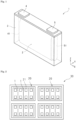
- Patent Document 1 describes a secondary battery including an electrode assembly formed by stacking a positive electrode and a negative electrode in a stacking direction with a separator interposed therebetween, an aluminum battery case housing the electrode assembly, an insulating film provided between the electrode assembly and an inner wall of the battery case, and a binding member disposed outside the battery case and binding the electrode assembly while pressurizing the electrode assembly in the stacking direction with the battery case and the insulating film interposed therebetween.
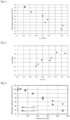
- the present invention has been made in view of the foregoing circumstances, and an object of the present invention is to provide an energy storage device in which a load is applied to an electrode assembly, and a decrease in discharge capacity at a high current density is suppressed.
- An energy storage device includes: an electrode assembly in which a positive electrode and a negative electrode are stacked with a separator interposed between the positive electrode and the negative electrode; an electrolyte solution; and a case which houses the electrode assembly and the electrolyte solution, in which the electrode assembly is in a state where a load is applied, a pressure P 0 (MPa) applied to the electrode assembly in a discharged state, and a strain A obtained when the separator is compressed in a thickness direction under an environment of 45°C at a pressure of 2 MPa satisfy the following Formula 1.
- the void of the negative electrode returns to the original size with the discharge, and the electrolyte solution flows into the void from the outside of the electrode assembly; however, in the discharge at a high current density, the inflow of the electrolyte solution does not catch up, and an amount of the electrolyte solution around the active material of the negative electrode locally decreases, so that reaction resistance increases, and the discharge capacity decreases.
- the separator in which the strain A is close to 0, that is, which is hardly compressed is not sufficiently compressed when the active material of the negative electrode expands with charge; however, the pressure difference (P 1 -P 0 ) can be reduced by further reducing the pressure P 0 .
- the pressure difference (P 1 -P 0 ) can be reduced by further reducing the pressure P 0 .
- the strain A is a value obtained by the following Formula 2 from an average thickness T a of the separator in a no-load state under an environment of 45°C and an average thickness T b of the separator in a state of being compressed in the thickness direction under an environment of 45°C at a pressure of 2 MPa.
- the average thickness of the separator is regarded as an average of measured values of thicknesses measured at any five points.
- A T a ⁇ T b / T a
- a value obtained by dividing the load applied to the electrode assembly by an area of a contact surface between a probe of the compression tester and the energy storage device is defined as a pressure applied to the electrode assembly. This measurement is performed on each of the energy storage devices in the discharged state and the charged state.
- the “charged state” and the “discharged state” of the energy storage device refer to a state where the following operation is performed.
- the energy storage device is subjected to constant current charge with a current of 1.0 C until the voltage becomes an end-of-charge voltage under normal usage, and then to constant voltage charge for 3 hours, this state is referred to as the "charged state”.
- a state where constant current discharge is performed with a current of 1.0 C up until the voltage becomes the lower limit voltage under normal usage after a pause of 10 minutes from the achievement of the charged state is referred to as the “discharged state”.
- the “during normal usage” herein means use of the energy storage device while employing charge-discharge conditions recommended or specified in the energy storage device, and when a charger is prepared for the energy storage device, this term means use of the energy storage device by applying the charger.
- the strain A is preferably 0.05 or more and 0.3 or less.
- the strain A is equal to or more than the above lower limit, sufficient compression occurs when a load is applied to the separator in the thickness direction, and therefore, the decrease in discharge capacity at a high current density when a sufficient load is applied to the electrode assembly is further suppressed.
- the strain A is equal to or less than the above upper limit, when a load is applied to the separator in the thickness direction, the decrease in ion permeability due to excessive compression is suppressed, and the decrease in discharge capacity at a high current density when a sufficient load is applied to the electrode assembly is further suppressed.
- the separator preferably has air permeability resistance of 250 seconds/100 mL or less. In such a case, sufficient ion permeability can be secured even in a state where the separator is compressed, and therefore, the decrease in discharge capacity at a high current density when a load is applied to the electrode assembly is further suppressed.
- the "air permeability resistance" of the separator is a value measured in accordance with JIS-P8117 (2009), and is an average value measured at any 5 points.
- the pressure P 0 is preferably 0.40 MPa or more and 1.40 MPa or less. In such a case, application of an excessive pressure to the electrode assembly is further suppressed, whereby the decrease in discharge capacity at a high current density is further suppressed.
- the pressure P 0 is equal to or more than the above lower limit, the gap in the electrode assembly is reduced, and gas generated by charging and discharging is less likely to be accumulated in the electrode assembly; therefore, the energy density and a discharge capacity retention ratio in a charge-discharge cycle can be increased, for example.
- the pressure P 1 is preferably 1.30 MPa or more and 2.00 MPa or less.
- the pressure P 1 is preferably 1.30 MPa or more and 2.00 MPa or less.
- the average thickness of the separator is preferably 3 pm or more and 100 pm or less.
- the average thickness of the separator is equal to or more than the above lower limit, it is possible to reliably electrically isolate the positive electrode and the negative electrode from each other, it is possible to sufficiently absorb an increase in the thickness of the negative electrode that expands with charge by compression of the separator, and it is possible to sufficiently reduce the difference (P 1 -P 0 ) between the pressure P 1 and the pressure P 0 .
- the average thickness of the separator is equal to or less than the above upper limit, the energy density of the energy storage device can be increased.
- the separator preferably includes a substrate layer and a coating layer containing particles and a binder formed on one surface or both surfaces of the substrate layer. In such a case, strength of the separator can be increased.
- An energy storage apparatus includes the energy storage device described above.
- the energy storage apparatus preferably includes the energy storage device bound in a constant size. In such a case, the effect of suppressing the decrease in discharge capacity at a high current density can be particularly sufficiently obtained.
- An automobile according to another aspect of the present invention includes the energy storage device described above.
- a power source for an electronic device includes the energy storage device described above.
- An energy storage device includes: an electrode assembly in which a positive electrode and a negative electrode are stacked with a separator interposed between the positive electrode and the negative electrode; an electrolyte solution; and a case which houses the electrode assembly and the electrolyte solution, in which the electrode assembly is in a state where a load is applied, and a difference between a pressure P 0 applied to the electrode assembly in a discharged state and a pressure P 1 applied to the electrode assembly in a charged state is 0.90 MPa or less.
- An energy storage device is an energy storage device in which a load is applied to an electrode assembly, and a decrease in discharge capacity at a high current density is suppressed.
- a load is applied to an electrode assembly, and a decrease in discharge capacity at a high current density is suppressed.
- the reason why such an effect is produced is not clear, the following reason is presumed.
- the difference (P 1 -P 0 ) between the pressure P 0 applied to the electrode assembly in the discharged state and the pressure P 1 applied to the electrode assembly in the charged state is as small as 0.90 MPa or less, the decrease in the conductivity of the negative electrode and the outflow of the electrolyte solution from the gap of the negative electrode hardly occur even in the charged state. From the above, it is presumed that according to the energy storage device according to another aspect of the present invention, although a load is applied to the electrode assembly, the decrease in discharge capacity at a high current density is suppressed.
- An energy storage device according to an embodiment of the present invention, an energy storage apparatus, a method for manufacturing the energy storage device, and other embodiments will be described in detail.
- the names of the constituent members (constituent elements) used in the embodiments may be different from the names of the constituent members (constituent elements) used in the background art.
- An energy storage device includes: an electrode assembly including a positive electrode, a negative electrode, and a separator; an electrolyte solution; and a case that houses the electrode assembly and the electrolyte solution.
- the positive electrode and the negative electrode are stacked with a separator interposed therebetween.
- the electrode assembly is usually a stacked type in which a plurality of positive electrodes and a plurality of negative electrodes are stacked with a separator interposed therebetween, or a wound type in which a positive electrode and a negative electrode are wound in a state of being stacked with a separator interposed therebetween.
- the electrolyte solution is present with the positive electrode, negative electrode, and separator impregnated with the electrolyte.
- a nonaqueous electrolyte solution secondary battery (hereinafter, also simply referred to as a "secondary battery”) will be described as an example of the energy storage device.
- the positive electrode has a positive substrate and a positive active material layer disposed directly on the positive substrate or over the positive substrate with an intermediate layer interposed therebetween.
- the positive substrate has conductivity. Whether the positive substrate has "conductivity" or not is determined with the volume resistivity of 10 7 ⁇ cm measured in accordance with JIS-H-0505 (1975) as a threshold.
- a metal such as aluminum, titanium, tantalum, or stainless steel, or an alloy thereof is used. Among these metals and alloys, aluminum or an aluminum alloy is preferable from the viewpoints of electric potential resistance, high conductivity, and cost.
- the positive substrate include a foil, a deposited film, a mesh, and a porous material, and a foil is preferable from the viewpoint of cost. Accordingly, the positive substrate is preferably an aluminum foil or an aluminum alloy foil. Examples of the aluminum or aluminum alloy include A1085, A3003, A1N30, and the like specified in JIS-H-4000 (2014) or JIS-H4160 (2006).
- the average thickness of the positive substrate is preferably 3 pm or more and 50 pm or less, more preferably 5 pm or more and 40 pm or less, still more preferably 8 pm or more and 30 pm or less, and particularly preferably 10 pm or more and 25 pm or less.
- the intermediate layer is a layer arranged between the positive substrate and the positive active material layer.
- the intermediate layer includes a conductive agent such as carbon particles to reduce contact resistance between the positive substrate and the positive active material layer.
- the configuration of the intermediate layer is not particularly limited, and includes, for example, a binder and a conductive agent.
- the positive active material layer includes a positive active material.
- the positive active material layer contains optional components such as a conductive agent, a binder (binding agent), a thickener, a filler, or the like as necessary.
- the positive active material can be appropriately selected from known positive active materials.
- As the positive active material for a lithium ion secondary battery a material capable of occluding and releasing lithium ions is typically used.
- Examples of the positive active material include lithium-transition metal composite oxides that have an ⁇ -NaFeO 2 -type crystal structure, lithium-transition metal composite oxides that have a spinel-type crystal structure, polyanion compounds, chalcogenides, and sulfur.
- the polyanion compounds include LiFePO 4 , LiMnPO 4 , LiNiPO 4 , LiCoPO 4 , Li 3 V 2 (PO 4 ) 3 , Li 2 MnSiO 4 , and Li 2 CoPO 4 F.
- the chalcogenides include a titanium disulfide, a molybdenum disulfide, and a molybdenum dioxide. Some of atoms or polyanions in these materials may be substituted with atoms or anion species composed of other elements. The surfaces of these materials may be coated with other materials. In the positive active material layer, one of these materials may be used singly, or two or more thereof may be used in mixture.
- the positive active material is usually a particle (powder).
- the average particle size of the positive active material is preferably 0.1 pm or more and 20 pm or less, for example. By setting the average particle size of the positive active material to be equal to or more than the lower limit mentioned above, the positive active material is easily manufactured or handled. By setting the average particle size of the positive active material to be equal to or less than the upper limit mentioned above, the electron conductivity of the positive active material layer is improved. In the case of using a composite of the positive active material and another material, the average particle size of the composite is regarded as the average particle size of the positive active material.
- the "average particle size” means a value at which a volume-based integrated distribution calculated in accordance with JIS-Z-8819-2 (2001) is 50% based on a particle size distribution measured by a laser diffraction/scattering method for a diluted solution obtained by diluting particles with a solvent in accordance with JIS-Z-8825 (2013).
- a crusher or a classifier is used to obtain a powder with a predetermined particle size.
- the crushing method include a method of using a mortar, a ball mill, a sand mill, a vibratory ball mill, a planetary ball mill, a jet mill, a counter jet mill, a whirling airflow-type jet mill, a sieve, or the like.
- wet-type crushing in coexistence of water or an organic solvent such as hexane can also be used.
- a classification method a sieve or a wind force classifier or the like is used based on the necessity both in dry manner and in wet manner.
- the content of the positive active material in the positive active material layer is preferably 50% by mass or more and 99% by mass or less, more preferably 70% by mass or more and 98% by mass or less, and still more preferably 80% by mass or more and 95% by mass or less.
- the content of the conductive agent in the positive active material layer is preferably 1% by mass or more and 10% by mass or less, more preferably 3% by mass or more and 9% by mass or less.
- binder examples include: thermoplastic resins such as fluororesin (polytetrafluoroethylene (PTFE), polyvinylidene fluoride (PVDF), etc.), polyethylene, polypropylene, polyacryl, and polyimide; elastomers such as ethylene-propylene-diene rubber (EPDM), sulfonated EPDM, styrene-butadiene rubber (SBR), and fluororubber; and polysaccharide polymers.
- thermoplastic resins such as fluororesin (polytetrafluoroethylene (PTFE), polyvinylidene fluoride (PVDF), etc.), polyethylene, polypropylene, polyacryl, and polyimide
- elastomers such as ethylene-propylene-diene rubber (EPDM), sulfonated EPDM, styrene-butadiene rubber (SBR), and fluororubber
- EPDM ethylene-propylene-diene rubber
- SBR
- the content of the binder in the positive active material layer is preferably 1% by mass or more and 10% by mass or less, more preferably 3% by mass or more and 9% by mass or less.
- the thickener examples include polysaccharide polymers such as carboxymethylcellulose (CMC), and methylcellulose.
- CMC carboxymethylcellulose
- methylcellulose examples include polysaccharide polymers such as carboxymethylcellulose (CMC), and methylcellulose.
- the functional group may be deactivated by methylation or the like in advance.
- the filler is not particularly limited.
- the filler include polyolefins such as polypropylene and polyethylene, inorganic oxides such as silicon dioxide, alumina, titanium dioxide, calcium oxide, strontium oxide, barium oxide, magnesium oxide and aluminosilicate, hydroxides such as magnesium hydroxide, calcium hydroxide and aluminum hydroxide, carbonates such as calcium carbonate, hardly soluble ionic crystals of calcium fluoride, barium fluoride, and barium sulfate, nitrides such as aluminum nitride and silicon nitride, and substances derived from mineral resources, such as talc, montmorillonite, boehmite, zeolite, apatite, kaolin, mullite, spinel, olivine, sericite, bentonite and mica, or artificial products thereof.
- mineral resources such as talc, montmorillonite, boehmite, zeolite, apatite, kaolin,
- the negative electrode has a negative substrate and a negative active material layer disposed directly on the negative substrate or over the negative substrate with an intermediate layer interposed therebetween.
- the configuration of the intermediate layer is not particularly limited, and can be selected from the configurations exemplified for the positive electrode, for example.
- the negative substrate has conductivity.
- a metal such as copper, nickel, stainless steel, nickel-plated steel, or aluminum, an alloy thereof, a carbonaceous material, or the like is used.
- copper or a copper alloy is preferable.
- the negative substrate include a foil, a deposited film, a mesh, and a porous material, and a foil is preferable from the viewpoint of cost. Accordingly, the negative substrate is preferably a copper foil or a copper alloy foil.
- the copper foil include rolled copper foils and electrolytic copper foils.
- the average thickness of the negative substrate is preferably 2 pm or more and 35 pm or less, more preferably 3 pm or more and 30 pm or less, still more preferably 4 pm or more and 25 pm or less, and particularly preferably 5 pm or more and 20 pm or less.
- the average thickness of the negative substrate is within the above range, it is possible to enhance the energy density per volume of a secondary battery while increasing the strength of the negative substrate.
- the negative active material layer contains a negative active material.
- the negative active material layer contains optional components such as a conductive agent, a binder, a thickener, and a filler, if necessary.
- the optional components such as a conductive agent, a binder, a thickener, and a filler can be selected from the materials exemplified for the positive electrode.
- the negative active material layer may contain a typical nonmetal element such as B, N, P, F, Cl, Br, or I, a typical metal element such as Li, Na, Mg, Al, K, Ca, Zn, Ga, Ge, Sn, Sr, and Ba or a transition metal element such as Sc, Ti, V, Cr, Mn, Fe, Co, Ni, Cu, Mo, Zr, Ta, Hf, Nb, or W as a component other than the negative active material, the conductive agent, the binder, the thickener, and the filler.
- a typical nonmetal element such as B, N, P, F, Cl, Br, or I
- a typical metal element such as Li, Na, Mg, Al, K, Ca, Zn, Ga, Ge, Sn, Sr, and Ba
- a transition metal element such as Sc, Ti, V, Cr, Mn, Fe, Co, Ni, Cu, Mo, Zr, Ta, Hf, Nb, or W as a component other than the negative active material,
- the electron conductivity of the positive active material layer is improved.
- a crusher or a classifier is used to obtain a powder with a predetermined particle size.
- a crushing method and a classification method can be selected from, for example, the methods exemplified for the positive electrode.
- the negative active material is a metal such as metal Li
- the negative active material may have the form of foil.
- the separator can be appropriately selected from known separators.
- a separator composed of only a substrate layer a separator in which a coating layer containing particles and a binder is formed on one surface or both surfaces of the substrate layer, or the like can be used.
- the form of the substrate layer of the separator include a woven fabric, a nonwoven fabric, and a porous resin film. Among these forms, a porous resin film is preferable from the viewpoint of strength, and a nonwoven fabric is preferable from the viewpoint of liquid retaining property of the nonaqueous electrolyte.
- the particles contained in the coating layer preferably have a mass loss of 5% or less when the temperature is raised from room temperature to 500°C in the air atmosphere of 1 atm, and more preferably have a mass loss of 5% or less when the temperature is raised from room temperature to 800°C.
- materials that have a mass loss equal to or less than a predetermined value include inorganic compounds.
- the coating layer may be an inorganic particle layer in which particles of an inorganic compound are used as the particles.
- the inorganic compounds include oxides such as iron oxide, silicon oxide, aluminum oxide, titanium dioxide, zirconium oxide, calcium oxide, strontium oxide, barium oxide, magnesium oxide and aluminosilicate; nitrides such as aluminum nitride and silicon nitride; carbonates such as calcium carbonate; sulfates such as barium sulfate; hardly soluble ionic crystals such as calcium fluoride, barium fluoride, barium titanate; covalently bonded crystals such as silicon and diamond; and substances derived from mineral resources, such as talc, montmorillonite, boehmite, zeolite, apatite, kaolin, mullite, spinel, olivine, sericite, bentonite, and mica, and artificial products thereof.
- oxides such as iron oxide, silicon oxide, aluminum oxide, titanium dioxide, zirconium oxide, calcium oxide, strontium oxide, barium oxide, magnesium oxide and aluminosilicate
- a porosity of the separator is preferably 80 vol% or less from the viewpoint of strength, and is preferably 20 vol% or more from the viewpoint of discharge performance.
- the term "porosity” herein is a volume-based value, and means a value measured with a mercury porosimeter.
- the air permeability resistance of the separator is preferably 50 sec/100 mL or more and 250 sec/100 mL or less, more preferably 80 sec/100 mL or more and 240 sec/100 mL or less, and still more preferably 120 sec/100 mL or more and 230 sec/100 mL or less.
- the air permeability resistance of the separator is within the above range, the decrease in discharge capacity at a high current density when a sufficient load is applied to the electrode assembly is further suppressed.
- the air permeability resistance of the separator is equal to or less than the above upper limit, sufficient ion permeability can be secured even in a state where the separator is compressed, and therefore, the decrease in discharge capacity at a high current density is further suppressed.
- the strain A obtained when the separator is compressed in the thickness direction under an environment of 45°C at a pressure of 2 MPa is preferably 0.05 or more and 0.3 or less, more preferably 0.10 or more and 0.25 or less, and still more preferably 0.20 or less in some cases.
- the strain A is equal to or more than the above lower limit, sufficient compression occurs when a load is applied to the separator in the thickness direction, and therefore, the decrease in discharge capacity at a high current density when a sufficient load is applied to the electrode assembly is further suppressed.
- the strain A is equal to or less than the above upper limit, when a load is applied to the separator in the thickness direction, the decrease in ion permeability due to excessive compression is suppressed, and the decrease in discharge capacity at a high current density when a sufficient load is applied to the electrode assembly is further suppressed.
- the strain A can be adjusted by the material, structure, porosity, and the like of the separator.
- the average thickness of the separator is preferably 3 pm or more and 100 pm or less, more preferably 5 pm or more and 50 pm or less, and still more preferably 10 pm or more and 30 pm or less.
- the average thickness of the separator is equal to or more than the above lower limit, it is possible to reliably electrically isolate the positive electrode and the negative electrode from each other, it is possible to sufficiently absorb the increase in the thickness of the negative electrode that expands with charge by compression of the separator, and it is possible to sufficiently reduce the pressure difference (P 1 -P 0 ).
- the average thickness of the separator is equal to or less than the above upper limit, the energy density of the secondary battery can be increased.
- the electrode assembly is in the state where a load is applied in all states from the discharged state to the charged state.
- the load on the electrode assembly is a load in the thickness direction of each of the positive electrode, the negative electrode, and the separator which are stacked, that is, in a stacking direction.
- the electrode assembly may have a portion to which no load is applied, such as an end of the electrode assembly.
- the energy density can be increased, and the discharge capacity retention ratio in the charge-discharge cycle can be increased.
- the reason why the discharge capacity retention ratio is increased by applying a load to the electrode assembly is not clear, it is presumed that, for example, the gap in the electrode assembly is reduced, and gas generated by charging and discharging is less likely to be accumulated in the electrode assembly.
- the load can be applied to the electrode assembly by a restraining member or the like described later.
- the difference (P 1 -P 0 ) between the pressure P 0 applied to the electrode assembly in the discharged state and the pressure P 1 applied to the electrode assembly in the charged state is 0.90 MPa or less.
- the pressure difference (P 1 -P 0 ) is preferably 0.85 MPa or less, and more preferably 0.80 MPa or less.
- the lower limit of the pressure difference (P 1 -P 0 ) may be 0 MPa, 0.20 MPa, 0.40 MPa, or 0.60 MPa.
- the pressure P 0 applied to the electrode assembly in the discharged state may be, for example, 0.10 MPa or more and 2.00 MPa or less, and is preferably 0.40 MPa or more and 1.40 MPa or less, more preferably 0.60 MPa or more and 1.10 MPa or less, and still more preferably 0.80 MPa or more and 1.00 MPa or less in some cases.
- the pressure P 0 By setting the pressure P 0 to be equal to or more than the above lower limit, the energy density, the discharge capacity retention ratio in the charge-discharge cycle, and the like can be increased.
- the pressure P 1 applied to the electrode assembly in the charged state may be, for example, 0.50 PMa or more and 2.90 MPa or less, and is preferably 0.80 MPa or more and 2.30 MPa or less, more preferably 1.30 MPa or more and 2.00 MPa or less, and still more preferably 1.40 MPa or more and 1.60 MPa or less in some cases.
- the pressure P 1 By setting the pressure P 1 to be equal to or more than the above lower limit, the energy density, the discharge capacity retention ratio in the charge-discharge cycle, and the like can be increased.
- the pressure P 1 to be equal to or less than the above upper limit application of an excessive pressure to the electrode assembly in the charged state is suppressed, and the decrease in discharge capacity at a high current density is further suppressed.
- the pressure P 0 (MPa) applied to the electrode assembly in the discharged state and the strain A obtained when the separator is compressed in the thickness direction under an environment of 45°C at a pressure of 2 MPa satisfy the following Formula 1.
- the upper limit of P 0 (1-A) is preferably 1.1, and more preferably 1.0, 0.9, 0.8, or 0.7 in some cases.
- P 0 (1-A) is less than the above upper limit or equal to or less than the above upper limit, the increase in pressure applied to the electrode assembly with charge, that is, the pressure difference (P 1 -P 0 ) is reduced, and therefore, the decrease in discharge capacity at a high current density is suppressed.
- the lower limit of P 0 (1-A) is more than 0, and may be 0.1, 0.3, 0.5, or 0.7.
- the nonaqueous electrolyte solution secondary battery includes a nonaqueous electrolyte solution as a nonaqueous electrolyte.
- the nonaqueous electrolyte solution can be appropriately selected from known nonaqueous electrolyte solutions.
- the nonaqueous electrolyte solution usually contains a nonaqueous solvent and an electrolyte salt dissolved in the nonaqueous solvent.
- the nonaqueous solvent can be appropriately selected from known nonaqueous solvents.
- the nonaqueous solvent include cyclic carbonates, chain carbonates, carboxylic acid esters, phosphoric acid esters, sulfonic acid esters, ethers, amides, and nitriles.
- the nonaqueous solvent those in which some hydrogen atoms contained in these compounds are substituted with halogen may be used.
- cyclic carbonate examples include ethylene carbonate (EC), propylene carbonate (PC), butylene carbonate (BC), vinylene carbonate (VC), vinylethylene carbonate (VEC), chloroethylene carbonate, fluoroethylene carbonate (FEC), difluoroethylene carbonate (DFEC), styrene carbonate, 1-phenylvinylene carbonate, and 1,2-diphenylvinylene carbonate.
- EC is preferable.
- chain carbonate examples include diethyl carbonate (DEC), dimethyl carbonate (DMC), ethyl methyl carbonate (EMC), diphenyl carbonate, trifluoroethyl methyl carbonate, and bis(trifluoroethyl)carbonate.
- DEC diethyl carbonate
- DMC dimethyl carbonate
- EMC ethyl methyl carbonate
- diphenyl carbonate trifluoroethyl methyl carbonate
- bis(trifluoroethyl)carbonate examples of the chain carbonate.
- EMC is preferable.
- the cyclic carbonate or the chain carbonate is preferably used, more preferably, the cyclic carbonate and the chain carbonate are used in combination.
- the use of the cyclic carbonate allows the promoted dissociation of the electrolyte salt to improve the ionic conductivity of the nonaqueous electrolyte solution.
- the use of the chain carbonate allows the viscosity of the nonaqueous electrolyte solution to be kept low.
- a volume ratio of the cyclic carbonate to the chain carbonate is preferably in a range from 5 : 95 to 50 : 50, for example.
- the electrolyte salt can be appropriately selected from known electrolyte salts.
- Examples of the electrolyte salt include a lithium salt, a sodium salt, a potassium salt, a magnesium salt, and an onium salt. Among these, a lithium salt is preferable.
- lithium salt examples include inorganic lithium salts such as LiPF 6 , LiPO 2 F 2 , LiBF 4 , LiClO 4 , and LiN(SO 2 F) 2 , lithium oxalates such as lithium bis(oxalate)borate (LiBOB), lithium difluorooxalatoborate (LiFOB), and lithium bis(oxalate)difluorophosphate (LiFOP), and lithium salts having a halogenated hydrocarbon group, such as LiSO 3 CF 3 , LiN(SO 2 CF 3 ) 2 , LiN(SO 2 C 2 F 5 ) 2 , LiN(SO 2 CF 3 )(SO 2 C 4 F 9 ), LiC(SO 2 CF 3 ) 3 , and LiC(SO 2 C 2 F 5 ) 3 .
- inorganic lithium salts are preferable, and LiPF 6 is more preferable.
- the content of the electrolyte salt in the nonaqueous electrolyte solution is, at 20°C under 1 atm, preferably 0.1 mol/dm 3 or more and 2.5 mol/dm 3 or less, more preferably 0.3 mol/dm 3 or more and 2.0 mol/dm 3 or less, still more preferably 0.5 mol/dm 3 or more and 1.7 mol/dm 3 or less, particularly preferably 0.7 mol/dm 3 or more and 1.5 mol/dm 3 or less.
- the content of the electrolyte salt is in the above range, it is possible to increase the ionic conductivity of the nonaqueous electrolyte solution.
- the nonaqueous electrolyte solution may contain an additive, besides the nonaqueous solvent and the electrolyte salt.
- the additive include aromatic compounds such as biphenyl, alkylbiphenyl, terphenyl, partly hydrogenated terphenyl, cyclohexylbenzene, t-butylbenzene, t-amylbenzene, diphenyl ether, and dibenzofuran; partial halides of the aromatic compounds such as 2-fluorobiphenyl, o-cyclohexylfluorobenzene, and p-cyclohexylfluorobenzene; halogenated anisole compounds such as 2,4-difluoroanisole, 2,5-difluoroanisole, 2,6-difluoroanisole, and 3,5-difluoroanisole; vinylene carbonate, methylvinylene carbonate, ethylvinylene carbonate, succinic anhydride, glutaric an
- the content of the additive contained in the nonaqueous electrolyte solution is preferably 0.01% by mass or more and 10% by mass or less, more preferably 0.1% by mass or more and 7% by mass or less, still more preferably 0.2% by mass or more and 5% by mass or less, and particularly preferably 0.3% by mass or more and 3% by mass or less, with respect to a total mass of the nonaqueous electrolyte solution.
- the content of the additive falls within the above range, thereby making it possible to improve capacity retention performance or cycle performance after high-temperature storage, and to further improve safety.
- the case is a sealed case that houses the electrode assembly and the nonaqueous electrolyte solution.
- the material of the case may be any material as long as it has sealability capable of sealing the electrode assembly and the nonaqueous electrolyte solution and strength capable of protecting the electrode assembly, and may be, for example, resin or metal.
- the case may be, for example, a case such as a flexible bag body formed of a composite film or the like in which a heat-weldable resin and a metal foil are stacked.
- Fig. 1 illustrates an energy storage device 1 as an example of a prismatic battery.
- Fig. 1 is a view illustrating the inside of a case in a perspective manner.
- An electrode assembly 2 including a positive electrode and a negative electrode wound with a separator interposed therebetween is housed in a prismatic battery case 3.
- An electrolyte solution (not illustrated) such as a nonaqueous electrolyte solution is further stored in the case 3.
- the positive electrode is electrically connected to a positive electrode terminal 4 via a positive electrode lead 41.
- the negative electrode is electrically connected to a negative electrode terminal 5 via a negative electrode lead 51.
- the load can be applied to the electrode assembly 2 in the energy storage device 1 of Fig. 1 by, for example, a restraining member (not illustrated) which pressurizes the case 3 from the outside.
- the restraining member may be a binding member that binds the shape of the case 3.
- the restraining member (binding member) is provided so as to sandwich the electrode assembly 2 from both surfaces (a surface on a front side and a surface on a depth side in Fig. 1 ) in the thickness direction (stacking direction: Y direction in Fig. 1 ) with the case 3 interposed between the restraining member and the electrode assembly 2 and to pressurize the case 3.
- Both surfaces of the electrode assembly 2 are in contact with an inner surface of the case 3 directly or with another member (not illustrated) interposed therebetween.
- a load is applied to the electrode assembly 2 by pressurizing the case 3.
- Both surfaces of the electrode assembly 2 are preferably in contact with the inner surface of the case 3 directly or with another member (not illustrated) interposed therebetween in a state where the case 3 is not pressurized.
- the restraining member include a binding band and a metallic frame.
- the plurality of energy storage devices 1 may be arranged in a row in the stacking direction (Y direction in Fig. 1 , horizontal direction in Fig. 2 ) of the electrode assembly 2, and may be fixed by using a binding member 21 such as a frame in a state where the plurality of energy storage devices 1 are pressurized from both ends in the stacking direction.
- binding in a constant size means that the energy storage device is bound such that the size and shape of the energy storage device do not substantially change.
- the binding member and the energy storage device are not substantially deformed after the binding member is attached to the energy storage device, and therefore, there is an advantage that designing becomes easy.
- a load applied to the electrode assembly tends to increase due to expansion of the energy storage device at the time of charging, and therefore, in general, the pressure difference (P 1 -P 0 ) tends to increase. For this reason, when an embodiment of the present invention is applied to the energy storage device in which the binding member for binding in a constant size is used, the effect of suppressing the decrease in discharge capacity at a high current density can be particularly sufficiently obtained.
- the energy storage device of the present embodiment can be mounted as an energy storage unit (battery module) configured by assembling a plurality of energy storage devices on a power source for an automobile such as electric vehicles (EV), hybrid vehicles (HEV), and plug-in hybrid vehicles (PHEV), a power source for electronic devices such as personal computers and communication terminals, or a power source for power storage, or the like.
- a power source for an automobile such as electric vehicles (EV), hybrid vehicles (HEV), and plug-in hybrid vehicles (PHEV)
- a power source for electronic devices such as personal computers and communication terminals
- a power source for power storage or the like.
- the technique of the present invention may be applied to at least one energy storage device included in the energy storage apparatus.
- Fig. 2 shows an example of an energy storage apparatus 30 formed by assembling energy storage units 20 in each of which two or more electrically connected energy storage devices 1 are assembled.
- the energy storage unit 20 the plurality of energy storage devices 1 are arranged in the thickness direction with no gap therebetween, and the energy storage devices 1 are bound by the binding member 21 having a constant size such that the thickness is maintained constant and the energy storage devices 1 are pressurized from the thickness direction (horizontal direction in Fig. 2 ).
- the energy storage apparatus 30 may include a busbar (not illustrated) for electrically connecting two or more energy storage devices 1, a busbar (not illustrated) for electrically connecting two or more energy storage units 20, and the like.
- the energy storage unit 20 or the energy storage apparatus 30 may include a state monitor (not illustrated) for monitoring the state of one or more energy storage devices.
- Housing the electrolyte solution in a case can be appropriately selected from known methods.
- the electrolyte solution may be injected from an injection port formed in the case, and then the injection port may be sealed.
- the manufacturing method may further include attaching a restraining member such as a binding member.
- a method for manufacturing an energy storage apparatus including a plurality of energy storage devices may include attaching a restraining member such as a binding member to the plurality of energy storage devices.
- the energy storage device according to the present invention is not to be considered limited to the embodiment mentioned above, and various changes may be made without departing from the scope of the present invention.
- the configuration of another embodiment can be added, and a part of the configuration of one embodiment can be replaced by the configuration of another embodiment or a well-known technique.
- a part of the configuration according to one embodiment can be deleted.
- a well-known technique can be added to the configuration according to one embodiment.
- the energy storage device is used as a nonaqueous electrolyte solution secondary battery (for example, lithium ion secondary battery) that can be charged and discharged has been described, but the type, shape, dimensions, capacity, and the like of the energy storage device are arbitrary.
- the present invention can also be applied to capacitors such as various secondary batteries, electric double layer capacitors, or lithium ion capacitors.
- a positive composite paste was prepared with the use of LiNi 0.6 Co 0.2 Mn 0.2 O 2 as a positive active material, acetylene black (AB) as a conductive agent, a polyvinylidene fluoride (PVDF) as a binder, and an N-methylpyrrolidone (NMP) as a dispersion medium. It is to be noted that the mass ratios of the positive active material, AB, and PVDF were set to be 90 : 5 : 5 (in terms of solid content).
- the positive composite paste was applied to both surfaces of an aluminum foil as a positive substrate, and dried. Thereafter, roll pressing was performed to obtain a positive electrode.
- Graphite as a negative active material, a styrene-butadiene rubber (SBR) as a binder, carboxymethyl cellulose (CMC) as a thickener, and water as a dispersion medium were mixed to prepare a negative composite paste.
- the mass ratio of the negative active material, SBR, and CMC was set to be 96 : 2 : 2 (in terms of solid content).
- the negative composite paste was applied to both surface of a copper foil as a negative substrate, and dried. Thereafter, roll pressing was performed to obtain a negative electrode.
- LiPF 6 was dissolved at a concentration of 1.2 mol/dm 3 in a solvent obtained by mixing an ethylene carbonate, a propylene carbonate, and an ethyl methyl carbonate at a volume ratio of 20 : 10 : 70 to obtain a nonaqueous electrolyte solution.
- a separator A in which a coating layer formed of inorganic particles and a binder was stacked on one surface of a substrate layer formed from a polyethylene porous resin film was used.
- the average thickness of the separator A was 21 pm
- the air permeability resistance was 90 seconds/100 mL
- the strain A strain obtained when the separator was compressed in the thickness direction under an environment of 45°C at a pressure of 2 MPa was 0.18.
- the positive electrode, the negative electrode, and the separator A were stacked to obtain an electrode assembly.
- the electrode assembly was sealed in a case formed of a composite film in which a heat-weldable resin and an aluminum foil were stacked, and a nonaqueous electrolyte solution was injected to seal the case.
- the energy storage device of Example 1 was obtained in a state where the binding member for binding in a constant size was attached and a load was applied such that the pressure P 0 applied to the electrode assembly in the discharged state was 1.31 MPa.
- Each energy storage device of Examples 2 to 7 and Comparative Examples 1 to 4 was obtained similarly to Example 1 except that the kind of the separator used and the pressure P 0 applied to the electrode assembly in the discharged state were changed as shown in Table 1.
- Table 1 shows the material of the substrate layer of each separator, the presence or absence of the coating layer, the average thickness, the air permeability resistance, the strain A (strain obtained when the separator was compressed in the thickness direction under an environment of 45°C at a pressure of 2 MPa), and the value of P 0 (1-A).
- the strain A was not measured.
- PE represents polyethylene
- PP represents polypropylene
- PP/PE/PP indicates a substrate layer having a three-layer structure in which PP, PE, and PP are stacked in this order.
- Each coating layer is a layer formed of inorganic particles and a binder.
- Each energy storage device of Examples and Comparative Examples was subjected to an initial charge-discharge step at 25°C under predetermined conditions, then subjected to constant current charge at 45°C with a current of 1.0 C until the voltage became 4.25 V, and then subjected to constant voltage charge at 4.25 V to be brought into the charged state.
- the charge time was set to 3 hours by combining the constant current charge and the constant voltage charge.
- the pressure P 1 applied to the electrode assembly in the charged state was measured.
- the measured pressure P 1 and the pressure difference (P 1 -P 0 ) are shown in Table 1.
- Each energy storage device of Examples 1 to 4 and Comparative Examples 1 to 4 which were brought into the charged state by the measurement of the pressure P 1 was subjected to constant current discharge with a current of 3.0 C at 45°C until the voltage became 2.75 V, and the discharge capacity X was obtained. Furthermore, each energy storage device of Examples 1 to 4 and Comparative Examples 1 to 4 was brought into a state where a load was not substantially applied to the electrode assembly, and a discharge capacity Y with a current of 3.0 C was obtained similarly to the above. The percentage of the discharge capacity X with respect to the discharge capacity Y in each energy storage device was obtained as a discharge capacity ratio (%). The results are shown in Table 1.
- Fig. 3 shows a relationship between the pressure difference (P 1 -P 0 ) and the discharge capacity ratio in each energy storage device of Examples 1 to 4 and Comparative Examples 1 to 4.
- Fig. 4 shows a relationship between P 0 (1-A) and the pressure difference (P 1 -P 0 ) in each energy storage device of Examples 1 and 4 to 7 and Comparative Examples 1 and 4.
- the discharge capacity ratio had a high correlation with the pressure difference (P 1 -P 0 ) between the charged state and the discharged state, and when the pressure difference (P 1 -P 0 ) was 0.90 MPa or less, the discharge capacity ratio was 86% or more. That is, it is found that when the pressure difference (P 1 -P 0 ) is 0.90 MPa or less, the decrease in discharge capacity at a high current density in the energy storage device to which a load is applied to the electrode assembly can be sufficiently suppressed.
- a positive composite paste was prepared with the use of LiNi 0.6 Co 0.2 Mn 0.2 O 2 as a positive active material, acetylene black (AB) as a conductive agent, a polyvinylidene fluoride (PVDF) as a binder, and an N-methylpyrrolidone (NMP) as a dispersion medium. It is to be noted that the mass ratios of the positive active material, AB, and PVDF were set to be 90 : 5 : 5 (in terms of solid content).
- the positive composite paste was applied to both surfaces of an aluminum foil as a positive substrate, and dried. Thereafter, roll pressing was performed to obtain a positive electrode.
- Graphite as a negative active material, a styrene-butadiene rubber (SBR) as a binder, carboxymethyl cellulose (CMC) as a thickener, and water as a dispersion medium were mixed to prepare a negative composite paste.
- the mass ratio of the negative active material, SBR, and CMC was set to be 96 : 2 : 2 (in terms of solid content).
- the negative composite paste was applied to both surface of a copper foil as a negative substrate, and dried. Thereafter, roll pressing was performed to obtain a negative electrode.
- LiPF 6 was dissolved at a concentration of 1.0 mol/dm 3 in a solvent obtained by mixing an ethylene carbonate, a propylene carbonate, and an ethyl methyl carbonate at a volume ratio of 25 : 5 : 70 to obtain a nonaqueous electrolyte solution.
- a separator (total average thickness 16 pm) in which a coating layer (thickness 4 pm, porosity 70 vol%) formed of inorganic particles and a binder was stacked on one surface of a substrate layer (average thickness 12 pm, porosity 40 vol%) including a porous resin film made of polyolefin was used.
- the positive electrode, the negative electrode, and the separator were stacked to obtain an electrode assembly.
- the electrode assembly was sealed in a case, and a nonaqueous electrolyte solution was injected to seal the case.
- the energy storage device of Reference Example 1 was obtained in a state where the binding member for binding in a constant size was attached and a load was applied such that the pressure P 0 applied to the electrode assembly in the discharged state was 0.1 MPa.
- An energy storage device of Reference Example 2 was obtained similarly to Reference Example 1 except that a binding member for binding in a constant size was attached so that no load was applied to the electrode assembly.
- Each energy storage device of Reference Examples 1 and 2 was subjected to the initial charge-discharge step at 25°C under predetermined conditions, and then subjected to the following charge-discharge cycle test.
- the energy storage device was subjected to constant current charge at 60°C with a current of 1.0 C until the voltage became 4.25 V, and then subjected to constant voltage charge at 4.25 V With regard to the charge termination conditions, charge was performed until the total charge time reached 3 hours. Thereafter, a pause period of 10 minutes was provided. Constant current discharge was performed with a current of 1.0 C until the voltage became 2.75 V, and then a pause period of 10 minutes was provided.
- the charging and discharging steps constituted one cycle, and the cycle was performed 900 cycles.
- Fig. 5 shows a graph showing the discharge capacity retention ratio based on the discharge capacity at the first cycle in the charge-discharge cycle test.
- the energy storage device of Reference Example 1 in which the binding member for binding in a constant dimension is attached so that a load is applied to the electrode assembly has a high discharge capacity retention ratio in the charge-discharge cycle as compared with the energy storage device of Reference Example 2 in which the binding member for binding in a constant size is attached so that no load is applied to the electrode assembly.
- the present invention can be applied to an energy storage device used as a power source for electronic devices such as personal computers and communication terminals, motor vehicles, and the like.
Applications Claiming Priority (2)
| Application Number | Priority Date | Filing Date | Title |
|---|---|---|---|
| JP2021063142 | 2021-04-01 | ||
| PCT/JP2022/015290 WO2022210643A1 (ja) | 2021-04-01 | 2022-03-29 | 蓄電素子 |
Publications (1)
| Publication Number | Publication Date |
|---|---|
| EP4300524A1 true EP4300524A1 (de) | 2024-01-03 |
Family
ID=83459376
Family Applications (1)
| Application Number | Title | Priority Date | Filing Date |
|---|---|---|---|
| EP22780854.0A Pending EP4300524A1 (de) | 2021-04-01 | 2022-03-29 | Stromspeicherelement |
Country Status (4)
| Country | Link |
|---|---|
| EP (1) | EP4300524A1 (de) |
| JP (1) | JPWO2022210643A1 (de) |
| CN (1) | CN117121260A (de) |
| WO (1) | WO2022210643A1 (de) |
Family Cites Families (4)
| Publication number | Priority date | Publication date | Assignee | Title |
|---|---|---|---|---|
| US20150357635A1 (en) * | 2013-01-31 | 2015-12-10 | Sanyo Electric Co., Ltd. | Flat nonaqueous electrolyte secondary battery and battery pack |
| JP6128391B2 (ja) * | 2014-02-03 | 2017-05-17 | トヨタ自動車株式会社 | 非水電解液二次電池および組電池 |
| JP2018045797A (ja) | 2016-09-12 | 2018-03-22 | トヨタ自動車株式会社 | 二次電池 |
| JP7147157B2 (ja) * | 2017-11-30 | 2022-10-05 | 株式会社Gsユアサ | 蓄電素子 |
-
2022
- 2022-03-29 JP JP2023511332A patent/JPWO2022210643A1/ja active Pending
- 2022-03-29 EP EP22780854.0A patent/EP4300524A1/de active Pending
- 2022-03-29 CN CN202280022443.3A patent/CN117121260A/zh active Pending
- 2022-03-29 WO PCT/JP2022/015290 patent/WO2022210643A1/ja active Application Filing
Also Published As
| Publication number | Publication date |
|---|---|
| CN117121260A (zh) | 2023-11-24 |
| WO2022210643A1 (ja) | 2022-10-06 |
| JPWO2022210643A1 (de) | 2022-10-06 |
Similar Documents
| Publication | Publication Date | Title |
|---|---|---|
| JP2022075345A (ja) | 蓄電素子用正極及び蓄電素子 | |
| US20230112577A1 (en) | Energy storage device | |
| EP4109586A1 (de) | Positivelektrode für energiespeicherelement und energiespeicherelement | |
| US20230055059A1 (en) | Energy storage device, method for manufacturing energy storage device, and energy storage apparatus | |
| EP4300524A1 (de) | Stromspeicherelement | |
| EP4336581A1 (de) | Energiespeicherelement und energiespeichervorrichtung | |
| EP4250419A1 (de) | Energiespeicherelement mit wasserfreiem elektrolyt, elektronische vorrichtung und automobil | |
| EP4310939A1 (de) | Elektrisches energiespeicherelement | |
| EP4047678A1 (de) | Elektrizitätsspeicherelement und elektrizitätsspeichervorrichtung | |
| EP4322258A1 (de) | Energiespeicherelement mit wasserfreiem elektrolyt und energiespeichervorrichtung | |
| EP4290617A1 (de) | Energiespeicherelement mit wasserfreiem elektrolyt | |
| EP4276862A1 (de) | Stromspeicherelement | |
| EP4343910A1 (de) | Energiespeicherelement | |
| US20240154180A1 (en) | Energy storage device and method for manufacturing the same | |
| WO2023145677A1 (ja) | 非水電解質蓄電素子 | |
| WO2022176836A1 (ja) | 蓄電素子 | |
| US20230155180A1 (en) | Energy storage device, method for manufacturing the same and energy storage apparatus | |
| EP4280330A1 (de) | Energiespeicherelement mit wasserfreiem elektrolyt | |
| WO2023074559A1 (ja) | 蓄電素子 | |
| EP4325596A1 (de) | Energiespeicherelement | |
| EP4297122A1 (de) | Positivelektrodenaktivmaterial für energiespeicherelemente mit wasserfreiem elektrolyt, positivelektrode für energiespeicherelemente mit wasserfreiem elektrolyt, energiespeichereinheit und energiespeichervorrichtung | |
| WO2023008012A1 (ja) | 蓄電素子及び蓄電装置 | |
| US20240136610A1 (en) | Energy storage device | |
| WO2023100801A1 (ja) | 非水電解質蓄電素子、機器及び非水電解質蓄電素子の使用方法 | |
| WO2023248769A1 (ja) | 活物質粒子、電極、蓄電素子及び蓄電装置 |
Legal Events
| Date | Code | Title | Description |
|---|---|---|---|
| STAA | Information on the status of an ep patent application or granted ep patent |
Free format text: STATUS: THE INTERNATIONAL PUBLICATION HAS BEEN MADE |
|
| PUAI | Public reference made under article 153(3) epc to a published international application that has entered the european phase |
Free format text: ORIGINAL CODE: 0009012 |
|
| STAA | Information on the status of an ep patent application or granted ep patent |
Free format text: STATUS: REQUEST FOR EXAMINATION WAS MADE |
|
| 17P | Request for examination filed |
Effective date: 20230926 |
|
| AK | Designated contracting states |
Kind code of ref document: A1 Designated state(s): AL AT BE BG CH CY CZ DE DK EE ES FI FR GB GR HR HU IE IS IT LI LT LU LV MC MK MT NL NO PL PT RO RS SE SI SK SM TR |