EP4298024B1 - Partie externe en forme de manchon, récipient d'emballage combiné équipé de celle-ci, et procédé de séparation du récipient d'emballage combiné - Google Patents
Partie externe en forme de manchon, récipient d'emballage combiné équipé de celle-ci, et procédé de séparation du récipient d'emballage combiné Download PDFInfo
- Publication number
- EP4298024B1 EP4298024B1 EP22707701.3A EP22707701A EP4298024B1 EP 4298024 B1 EP4298024 B1 EP 4298024B1 EP 22707701 A EP22707701 A EP 22707701A EP 4298024 B1 EP4298024 B1 EP 4298024B1
- Authority
- EP
- European Patent Office
- Prior art keywords
- outer part
- container
- face
- packaging container
- combination packaging
- Prior art date
- Legal status (The legal status is an assumption and is not a legal conclusion. Google has not performed a legal analysis and makes no representation as to the accuracy of the status listed.)
- Active
Links
Images

Classifications
-
- B—PERFORMING OPERATIONS; TRANSPORTING
- B65—CONVEYING; PACKING; STORING; HANDLING THIN OR FILAMENTARY MATERIAL
- B65D—CONTAINERS FOR STORAGE OR TRANSPORT OF ARTICLES OR MATERIALS, e.g. BAGS, BARRELS, BOTTLES, BOXES, CANS, CARTONS, CRATES, DRUMS, JARS, TANKS, HOPPERS, FORWARDING CONTAINERS; ACCESSORIES, CLOSURES, OR FITTINGS THEREFOR; PACKAGING ELEMENTS; PACKAGES
- B65D1/00—Rigid or semi-rigid containers having bodies formed in one piece, e.g. by casting metallic material, by moulding plastics, by blowing vitreous material, by throwing ceramic material, by moulding pulped fibrous material or by deep-drawing operations performed on sheet material
- B65D1/22—Boxes or like containers with side walls of substantial depth for enclosing contents
- B65D1/26—Thin-walled containers, e.g. formed by deep-drawing operations
- B65D1/265—Drinking cups
-
- B—PERFORMING OPERATIONS; TRANSPORTING
- B65—CONVEYING; PACKING; STORING; HANDLING THIN OR FILAMENTARY MATERIAL
- B65D—CONTAINERS FOR STORAGE OR TRANSPORT OF ARTICLES OR MATERIALS, e.g. BAGS, BARRELS, BOTTLES, BOXES, CANS, CARTONS, CRATES, DRUMS, JARS, TANKS, HOPPERS, FORWARDING CONTAINERS; ACCESSORIES, CLOSURES, OR FITTINGS THEREFOR; PACKAGING ELEMENTS; PACKAGES
- B65D25/00—Details of other kinds or types of rigid or semi-rigid containers
- B65D25/34—Coverings or external coatings
- B65D25/36—Coverings or external coatings formed by applying sheet material
-
- B—PERFORMING OPERATIONS; TRANSPORTING
- B65—CONVEYING; PACKING; STORING; HANDLING THIN OR FILAMENTARY MATERIAL
- B65D—CONTAINERS FOR STORAGE OR TRANSPORT OF ARTICLES OR MATERIALS, e.g. BAGS, BARRELS, BOTTLES, BOXES, CANS, CARTONS, CRATES, DRUMS, JARS, TANKS, HOPPERS, FORWARDING CONTAINERS; ACCESSORIES, CLOSURES, OR FITTINGS THEREFOR; PACKAGING ELEMENTS; PACKAGES
- B65D3/00—Rigid or semi-rigid containers having bodies or peripheral walls of curved or partially-curved cross-section made by winding or bending paper without folding along defined lines
- B65D3/22—Rigid or semi-rigid containers having bodies or peripheral walls of curved or partially-curved cross-section made by winding or bending paper without folding along defined lines with double walls; with walls incorporating air-chambers; with walls made of laminated material
-
- B—PERFORMING OPERATIONS; TRANSPORTING
- B65—CONVEYING; PACKING; STORING; HANDLING THIN OR FILAMENTARY MATERIAL
- B65D—CONTAINERS FOR STORAGE OR TRANSPORT OF ARTICLES OR MATERIALS, e.g. BAGS, BARRELS, BOTTLES, BOXES, CANS, CARTONS, CRATES, DRUMS, JARS, TANKS, HOPPERS, FORWARDING CONTAINERS; ACCESSORIES, CLOSURES, OR FITTINGS THEREFOR; PACKAGING ELEMENTS; PACKAGES
- B65D81/00—Containers, packaging elements, or packages, for contents presenting particular transport or storage problems, or adapted to be used for non-packaging purposes after removal of contents
- B65D81/38—Containers, packaging elements, or packages, for contents presenting particular transport or storage problems, or adapted to be used for non-packaging purposes after removal of contents with thermal insulation
- B65D81/3865—Containers, packaging elements, or packages, for contents presenting particular transport or storage problems, or adapted to be used for non-packaging purposes after removal of contents with thermal insulation drinking cups or like containers
- B65D81/3869—Containers, packaging elements, or packages, for contents presenting particular transport or storage problems, or adapted to be used for non-packaging purposes after removal of contents with thermal insulation drinking cups or like containers formed with double walls, i.e. hollow
-
- B—PERFORMING OPERATIONS; TRANSPORTING
- B65—CONVEYING; PACKING; STORING; HANDLING THIN OR FILAMENTARY MATERIAL
- B65D—CONTAINERS FOR STORAGE OR TRANSPORT OF ARTICLES OR MATERIALS, e.g. BAGS, BARRELS, BOTTLES, BOXES, CANS, CARTONS, CRATES, DRUMS, JARS, TANKS, HOPPERS, FORWARDING CONTAINERS; ACCESSORIES, CLOSURES, OR FITTINGS THEREFOR; PACKAGING ELEMENTS; PACKAGES
- B65D81/00—Containers, packaging elements, or packages, for contents presenting particular transport or storage problems, or adapted to be used for non-packaging purposes after removal of contents
- B65D81/38—Containers, packaging elements, or packages, for contents presenting particular transport or storage problems, or adapted to be used for non-packaging purposes after removal of contents with thermal insulation
- B65D81/3865—Containers, packaging elements, or packages, for contents presenting particular transport or storage problems, or adapted to be used for non-packaging purposes after removal of contents with thermal insulation drinking cups or like containers
- B65D81/3874—Containers, packaging elements, or packages, for contents presenting particular transport or storage problems, or adapted to be used for non-packaging purposes after removal of contents with thermal insulation drinking cups or like containers formed of different materials, e.g. laminated or foam filling between walls
-
- B—PERFORMING OPERATIONS; TRANSPORTING
- B65—CONVEYING; PACKING; STORING; HANDLING THIN OR FILAMENTARY MATERIAL
- B65D—CONTAINERS FOR STORAGE OR TRANSPORT OF ARTICLES OR MATERIALS, e.g. BAGS, BARRELS, BOTTLES, BOXES, CANS, CARTONS, CRATES, DRUMS, JARS, TANKS, HOPPERS, FORWARDING CONTAINERS; ACCESSORIES, CLOSURES, OR FITTINGS THEREFOR; PACKAGING ELEMENTS; PACKAGES
- B65D81/00—Containers, packaging elements, or packages, for contents presenting particular transport or storage problems, or adapted to be used for non-packaging purposes after removal of contents
- B65D81/38—Containers, packaging elements, or packages, for contents presenting particular transport or storage problems, or adapted to be used for non-packaging purposes after removal of contents with thermal insulation
- B65D81/3876—Containers, packaging elements, or packages, for contents presenting particular transport or storage problems, or adapted to be used for non-packaging purposes after removal of contents with thermal insulation insulating sleeves or jackets for cans, bottles, barrels, etc.
-
- B—PERFORMING OPERATIONS; TRANSPORTING
- B65—CONVEYING; PACKING; STORING; HANDLING THIN OR FILAMENTARY MATERIAL
- B65D—CONTAINERS FOR STORAGE OR TRANSPORT OF ARTICLES OR MATERIALS, e.g. BAGS, BARRELS, BOTTLES, BOXES, CANS, CARTONS, CRATES, DRUMS, JARS, TANKS, HOPPERS, FORWARDING CONTAINERS; ACCESSORIES, CLOSURES, OR FITTINGS THEREFOR; PACKAGING ELEMENTS; PACKAGES
- B65D2565/00—Wrappers or flexible covers; Packaging materials of special type or form
- B65D2565/38—Packaging materials of special type or form
- B65D2565/381—Details of packaging materials of special type or form
- B65D2565/385—Details of packaging materials of special type or form especially suited for or with means facilitating recycling
Definitions
- the invention relates to a sleeve-shaped outer part formed from a blank for encasing a cup-shaped inner container, as well as to a combination packaging container formed from an inner container and the outer part.
- the invention also relates to a method for separating the combination packaging container into its inner container and the outer part by separating the overlapping area of the outer part.
- a predetermined separation region comprises an actuating means with a detection section for separating separation sections located on both sides.
- the detection section is arranged offset laterally from the separating sections, which are aligned convergingly and are spaced apart from an imaginary straight connecting line between them, as seen in the circumferential direction.
- a separate predetermined separation section is formed in the jacket of the outer part between each detection section end and a respective end of the separating sections. The lower end of the outer part facing the closed end of the inner container is supported on a support shoulder projecting radially outwards.
- the WO 2009/130043 A1 describes, among other things, a sleeve-shaped outer part for forming a combination packaging container.
- the outer part is formed from a blank by erecting and mutually connecting ends in an overlapping area.
- an actuating means for separating a predetermined separation area is provided, which is arranged between the two end areas spaced apart in the axial direction.
- the actuating means is formed by an opening extending up to the overlapping area, wherein the longitudinal side of the overlapping The end forms the detection section.
- an actuating tab is provided that can be removed from the casing along a U-shaped circumferential line, with the weakening line surrounding the actuating tab ending on the long side of the overlapping end.
- a packaging container has become known with a first container part having a container base and a container wall extending from the container base in the direction of a container edge, and with a second container part reinforcing the container wall in the form of a sleeve detachably connected to the first container part and at least partially lying against the outer surface of the container wall.
- the second container part has a weakening line running from an upper edge of the second container part facing the container rim towards a lower edge of the second container part facing the container bottom.
- the second container part can be detached from the first container part by cutting through the second container part along the weakening line.
- the second container part further has a gripping area that can be manually grasped to cut through the second container part, from which the second container part can be detached from the first container part.
- the weakening line has an engagement section that delimits the gripping area and has a reinforced weakening and/or a cutting line, which forms the starting section for cutting through the second container part along the weakening line. Furthermore, an access area is provided that adjoins the gripping area and lies on the side of the weakening line opposite the gripping area.
- the access area has two predetermined cutting lines that run transversely to the weakening line and end on one side in the engagement section of the weakening line. This ensures that, after separation along the predetermined separation lines and the engaging section, the access area remains firmly connected to the edge area of the second container part that does not have the gripping area.
- a perfect separation of the predetermined separation area adjacent to the gripping area could not be achieved in all applications.
- the object of the present invention was to overcome the disadvantages of the prior art and to provide a sleeve-shaped outer part and a combination packaging container comprising a cup-shaped inner container with a sleeve-shaped outer part surrounding the cup-shaped inner container.
- the sleeve-shaped outer part is securely positioned and held in the axial direction on the inner container without additional adhesive until the desired detachment from the inner container for recycling purposes.
- a method for separating the overlapping area and the subsequent separation of its outer part and inner container is also to be created.
- the advantage achieved in this way is that the support area or support section on the shoulder of the inner container, already defined by the first end face, is further improved by the provision or formation of the additional support device.
- the additional support device reduces the clear inner dimension compared to the undeformed configuration, thus achieving an even better locking effect on the inner container.
- tolerance-related manufacturing inaccuracies do not lead to any further disadvantages in the fixed positioning of the outer part on the inner container, and this is even possible without the adhesive point between the container shell and the outer part, which is otherwise usually applied for securing purposes. This creates an outer part that can also be more easily detached from the inner container for disposal.
- the additional support device comprises at least one support element, and the at least one support element defines the clear inner dimension.
- the at least one support element forms the additional support device and protrudes from the undeformed bottom-side edge region or edge section of the outer part in the direction of the longitudinal axis and forms the reduction of the clear inner dimension.
- the at least one support element is formed into the material of the blank, starting from an outer surface of the outer part toward an inner surface, and protrudes radially beyond the undeformed inner surface toward the longitudinal axis. This allows the material to be used directly to form the at least one support element, thus eliminating the need for additional components or parts. This also eliminates the need for additional material that would otherwise require separate treatment during separation and disposal.
- the at least one support element has a longitudinal extension starting from the first end face in the direction of the second end face. This allows a defined projection of the at least one support element can be realized via the inner surface of the cut or outer part, which forms the enlargement or widening of the base-side support area.
- Another possible embodiment has the features that multiple support elements are provided, and the support elements are arranged spaced apart from one another in the circumferential direction along the first end face. This allows for an even better support effect across the circumference, even under changing environmental conditions and/or during handling.
- the additional support device comprises at least one forming section, which is formed into the material of the blank from an inner surface of the outer part toward an outer surface, and which is arranged at a distance from the first end face. This subsequently allows the edge section to be aligned in the opposite direction.
- the at least one forming section viewed in axial section, has a preferably curved longitudinal profile, and an end section adjoining the forming section in the direction of the first end face is oriented so as to extend at an angle toward the longitudinal axis. This allows for additional stiffening of the bottom-side end section or the peripheral edge region.
- a further preferred embodiment is characterized in that the at least one forming section has a parallel longitudinal extension with respect to the first end face. This allows for a uniform design of the additional support device projecting toward the inner container.
- the forming section is arranged so as to extend continuously along the first end face in the circumferential direction. This allows a secure and uniform supporting effect to be achieved over the entire circumference, particularly in the case of inner containers with a round cross-sectional shape.
- Another alternative embodiment is characterized in that multiple forming sections are provided, and the forming sections are arranged spaced apart from one another in the circumferential direction along the first end face.
- This variant can be used in particular for inner containers that have rectilinear container walls when viewed in cross-section and each have a rounded corner region in the transition areas located therebetween. This prevents unwanted wrinkling in the transition areas.
- a further embodiment provides for an adhesive to be provided in the overlapping area between the two end sections, which adhesive has a first adhesive force value when viewed in the circumferential direction and a second adhesive force value in the radial direction, wherein the first adhesive force value is greater than the second adhesive force value. Due to the mutually different adhesive force values of the adhesive holding the blank together at its mutually facing end sections, on the one hand the cohesion can be made greater when viewed in the circumferential direction and, on the other hand, if the force is applied differently, an easier separation effect with a correspondingly reduced adhesive force can be made possible. This facilitates the separation process of the overlapping area when separating the outer part from the inner container. If a compressive force is exerted in the direction of the inner container, this can easily lead to a mutual detachment of the two interconnected end sections. This also allows a simple separation process of the outer part from the inner container during disposal.
- Another embodiment is characterized by the fact that at least one predetermined separation area is formed or provided in the outer shell of the outer part.
- at least one predetermined separation area is formed or provided in the outer shell of the outer part.
- the invention also relates to a combination packaging container comprising a cup-shaped inner container with a container shell, a base, a flange, a rear section located in the base area of the container shell and a shoulder as well as a A sleeve-shaped outer part designed according to the invention surrounds the inner container at least in part on its container shell.
- a further design provides for the sleeve-shaped outer part to be axially supported on the shoulder of the inner container by means of its additional support device, eliminating the need for an additional adhesive. This makes it even easier and, above all, more secure to separate the combination packaging container into the inner container and outer part after use. Even after the outer part has been separated, the outer part forms a single, integral piece, which can be easily and, above all, disposed of properly and recycled in one piece. Furthermore, by eliminating the additional adhesive, savings can be achieved and potential contamination of the machine during the adhesive application process can be avoided.
- the object of the invention is also achieved by a method for separating an outer part from an inner container, which together form the combination packaging container, in that a compressive force -F- directed towards the combination packaging container is applied during the separation process and the outer part and the container shell of the combination packaging container are spatially deformed and the applied compressive force -F- is at least partially converted into a separation force which at least partially separates the overlapping area by the spatial deformation.
- the applied compressive force -F- leads to a spatial deformation of the outer part and also of the container shell, whereby the compressive force -F- is at least partially deflected and converted into a separation force.
- the overlapping area of the outer part, held together by the adhesive or bonding agent is subjected to the separation force acting in the radial direction, depending on the orientation of the compressive force -F-.
- the separation force acting on the overlapping area causes the separation process, at least of the overlapping area.
- the person who is supposed to carry out the separation process can omit the search for and finding the actuating device for the desired separation area and the subsequent tearing process.
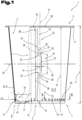
- a combination packaging container 1 is shown as an example of a multitude of possible different shapes, wherein the combination packaging containers 1 are cup- or bowl-shaped.
- the combination packaging container 1 comprises a cup- or bowl-shaped inner container 2 with a base 3 and a container shell 4.
- the inner container 2 further has an open end 5 on its side facing away from the base 3, wherein a flange 6 projecting outwardly beyond the container shell 4 can be provided in the region of its open end 5.
- the base 3 forms a closed end 7 for the container shell 4.
- the inner container 2 is preferably formed by a component produced in a deep-drawing process, which can be manufactured quickly and, above all, in a short cycle time.
- the deep-drawing process is well known and will therefore not be discussed in detail.
- the deep-drawing process is particularly suitable for producing the inner container 2 with a sufficient wall thickness to ensure tightness during storage, use, and disposal. This manufacturing process allows relatively thin walls of the inner container 2 to be produced.
- the inner container 2 can also be formed using other manufacturing processes, such as injection molding.
- a longitudinal axis 8 extends axially between the open end 5 and the end 7 closed by the base 3.
- This longitudinal axis 8 can also represent a central axis if the design is symmetrical.
- a sealing plate (not shown in detail) can be arranged in the area of the flange 6 or connected to it. In this case, the flange 6 forms a sealing flange.
- the inner container 2 In the axial direction and thus in the direction of the longitudinal axis 8, the inner container 2 has a container height 9 between its open end 5, in particular the flange 6, and the base 3, whereby the receiving volume of the inner container 2 is determined depending on the cross-sectional dimensions.
- the container height 9 in conjunction with the cross-sectional dimensions thus defines a receiving space of the inner container 2.
- the container shell 4 is understood to be that portion of the inner container 2 which extends predominantly axially between the open end 5, in particular the flange 6, and the base 3.
- the inner container 2 and its container shell 4 are preferably designed such that they taper conically from the open end toward the base.
- the container shell 4 of the inner container 2 can have a rear ledge 10 in its peripheral section adjacent to the base 3.
- the rear ledge 10 is also part of the container shell 4, but, viewed in axial section, is offset inwards with respect to an imaginary, straight connecting line between the flange 6 and the base 3.
- the rear ledge 10, in turn, has at least two rear ledge wall sections (not designated in more detail), wherein the two rear ledge wall sections, viewed in axial section, have a different inclination or direction with respect to the longitudinal axis 8 than the rest of the container shell 4.
- the rear ledge 10 is offset inwards and thus in the direction of the receiving space compared to the straight arrangement of the container shell 4 between the flange 6 and the base 3, viewed in axial section.
- the first rear-drawn wall section which directly adjoins the base 3, is arranged or configured to extend predominantly in the direction of the container height 9 toward the open end 5.
- the further rear-drawn wall section extends in a predominantly perpendicular direction with respect to the container height 9, starting from the end of the first rear-drawn wall section facing away from the base 3 toward the container shell 4.
- the further rear-drawn wall section forms a stacking shoulder. This stacking shoulder serves to support a similar combination packaging container 1 with its base 3, in particular the edge-side transition section between the base 3 and the container shell 4.
- the inner container 2 can have a shoulder 11 or a bead projecting towards the side facing away from the longitudinal axis 8 in the immediate transition area between the bottom 3 and the container shell 4, in particular between the bottom 3 and the rear section.
- the combination packaging container 1 further comprises an outer part 12 which is sleeve-shaped or jacket-shaped and surrounds the inner container 2 in the region of its container jacket 4 at least in sections or regions.
- the previously described shoulder 11 can, for example, serve to hold the sleeve-shaped outer part 12 on the inner container 2.
- the sleeve-shaped outer part 12 rests with its first end face 19 facing the bottom 3 of the inner container 2 on this shoulder 11 formed in the transition region.
- the shoulder 11 can thus also be referred to as a locking means for holding the outer part 12 on the inner container 2.
- the end face 19 forms a front edge in its longitudinal extent, which, in the joined position, defines a support area at least in sections and is supported against the shoulder.
- an unintentional detachment of the outer part 12 from the inner container 2 may occur.
- a further locking means in the region of the open end 5 can be, for example, the flange 6.
- the sleeve-shaped outer part 12 comprises a second end face 20, which in turn faces the open end 5 or the flange 6.
- the sleeve-shaped outer part 12 is preferably formed from a cellulose material, such as cardboard, with sufficient strength with regard to the absorption and transmission of, in particular, axially acting compressive forces, and is wound from a flat blank 13 into a sleeve, as is already well known.
- the blank 13 is usually printed in its undeformed, flat position and, if necessary, provided with an additional coating.
- a cellulose material is usually used as the material, although this can also be cardboard or strong paper produced using a recycling process. If a layer or ply of the outer part 12 is formed from a recycled material, an additional layer of a higher-quality paper can be arranged on or bonded to at least one of the surfaces. This additional layer ensures flawless printing for the production of decorations, labels, and product information.
- the sleeve-like or jacket-like outer part 12 leads to an additional reinforcement or stiffening effect of the inner container 2 and thus of the entire combination packaging container 1.
- the cardboard is additionally coated or sealed with a water-repellent material in the area of the cut edges. This is particularly advantageous when the combination packaging container 1 is exposed to increased moisture ingress. Coating the cardboard used for the outer part 12 with a water-repellent layer prevents the cardboard from swelling in a humid environment and ultimately detaching from the container shell 4 of the combination packaging container 1.
- the sleeve-shaped outer part 12 is wound from the mostly flat blank 13 into a sheath.
- end sections 14, 15 facing each other are then connected to one another in a simplified representation of the overlapping area 16.
- This is achieved by a so-called overlap seam, by means of which the first end section 14 and the second end section 15 adhere to one another, for example by means of an adhesive.
- the winding and subsequent connection of the two end sections 14, 15 can be carried out, as is already sufficiently known from the prior art, for example by gluing.
- the first end section 14 of the blank 13 ends with a first Longitudinal edge 17 and the second end section 15 in turn ends with a second longitudinal edge 18.
- the two longitudinal edges 17, 18 run approximately parallel to one another, wherein, viewed in the circumferential direction, the overlapping area 16 is formed therebetween with an overlap width.
- the outer part 12 further comprises the first end face 19 and the second end face 20, wherein the two end faces 19, 20 are spaced apart from one another and, in the erected state, define an overall height 21 of the shell.
- the previously described longitudinal axis 8 can also define the common longitudinal axis for the outer part 12, particularly when the outer part 12 is in its mounted position on the inner container 2.
- the overall height 21 of the shell is usually slightly less than the container height 9 of the inner container 2 in the same spatial direction—namely, in the direction of the longitudinal axis 8.
- predetermined separation area 22 is arranged and formed in the material of the outer part 12.
- the following detailed description of the predetermined separation area 22 corresponds to the design already described in the WO 2020/245148 A1 described. However, the predetermined separation area 22 could also be designed differently and deviating from this.
- At least one predetermined separation region 22 is provided in the casing of the outer part 12.
- the predetermined separation region 22 here comprises a first separation section 23, a second separation section 24, and an actuating means 25 for starting and initiating the severing process of the predetermined separation region 22 along the two separation sections 23, 24.
- the actuating means 25 is arranged between the two end faces 19, 20, viewed in the direction of the overall height 21 of the casing. It is advantageous if the actuating means 25 is arranged approximately centrally between the two end faces 19, 20, which are spaced apart from one another in the direction of the overall height 21, whereby this essentially corresponds to half the overall height 21.
- central refers to half the dimension of the actuating means 25 in the direction of the overall height 21 or the longitudinal axis 8.
- the two separating sections 23, 24 are provided on both sides of the actuating means 25 and each extend in the direction of the respective end face 19, 20.
- the two separating sections 23, 24 of the predetermined separating area 22 are each aligned so as to converge from the two end faces 19, 20 and thus define an imaginary, straight connecting line 26 between them, which is shown in dashed lines.
- the converging alignment of the two separating sections 23, 24 is in each case related to the direction of the actuating means 25.
- the two separating sections 23, 24 can either be aligned so as to be flush with one another, viewed in the direction of the overall height 21 of the casing, or they can run at a slight inclination with respect to the first longitudinal edge 17 in the direction of the actuating means 25 located between them. This slight inclination can further improve the separating process after the two separating sections 23, 24 have been separated towards the two end faces 19, 20.
- the imaginary connecting line 26 is assumed to run at the center of the predetermined separation points.
- the actuating means 25 defines a detection section 27 with a first detection section end 28 and a second detection section end 29 spaced apart from one another in the direction of the overall height 21.
- the two detection section ends 28, 29 are arranged or end at a distance 30 from one another in the direction of the overall height 21 of the casing.
- the detection section 27 of the actuating means 25 is arranged or formed outside the overlap region 16.
- the offset 31 can have a value selected from a range of values with a lower limit of 1.0 mm and an upper limit of 10.0 mm.
- the range of values can have a lower limit of 2.0 mm and an upper limit of 6.0 mm.
- the first separating section 23 in turn has a first end 32 facing the actuating means 25, wherein the second separating section 24 has a second end 33 facing the actuating means 25.
- the casing is formed without interruption due to the intended lateral offset 31 of the actuating means 25.
- the arrangement of the two in the direction The position of the ends 32, 33 of the separating sections 23, 24, which are spaced apart from one another by the overall height 21, with respect to the detection section 27 forming the actuating means 25 is selected such that the first detection section end 28 of the detection section 27 overlaps the adjacent first end 32 of the first separating section 23 on the side facing away from the second separating section 24.
- a first predetermined separating section 34 is formed in the casing of the outer part 12 between the first detection section end 28 and the first end 32 of the first separating section 23, as seen in the circumferential direction.
- the second detection section end 29 of the detection section 27 overlaps the adjacent second end 33 of the second separating section 24 on the side facing away from the first separating section 23.
- a second intended separating section 35 is also formed in the casing of the outer part 12 between the second detection section end 29 and the second end 33 of the second separating section 24, viewed in the circumferential direction.
- the two intended separating sections 34, 35 are formed by the reduced dimension of the casing material between the respective detection section end 28 or 29 and the respective end 32 or 33.
- the two ends 32 and 33 of the separating sections 23, 24 are arranged closer to one another than the two detection section ends 28 and 29, which are spaced apart by the distance 30.
- the two predetermined separation sections 34, 35 each form starting sections for the separation of the two separation sections 23, 24.
- Each of the two separating sections 23, 24 comprises a plurality of predetermined separation points arranged one behind the other in a row, which are usually formed as perforations, in particular also as short cuts, in the material of the outer part 12.
- first predetermined separation points 36 those predetermined separation points that are located directly adjacent to the respective detection section ends 28, 29 are referred to as first predetermined separation points 36.
- second predetermined separation points 37 and third predetermined separation points 38 are further predetermined separation points provided subsequently towards one of the two end faces 19, 20.
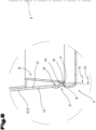
- the predetermined separation points 36, 37, 38 are aligned with respect to a plane 39 centrally and in normal alignment to the longitudinal axis 8 - see Fig. 1 - are designed and arranged in a mirror image of each other. Therefore, only those predetermined separation points 36, 37, 38 located in the area of the first separation section 23 will be described in more detail and are to be transferred analogously to the second separation section 24.
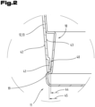
- an additional support device 40 is provided or formed by solely deforming the material of the blank 13.
- the additional support device 40 serves or is designed to ensure that the outer part 12 is or will be supported even more securely in the axial direction on the shoulder 11 of the inner container 2 until it is detached.
- the additional support device 40 is further designed such that a clear internal dimension of the finished formed outer part 12 is smaller than the undeformed design.
- the bottom end face 19 of the outer part 12 already forms or defines the support area interacting with the shoulder 11, which support area is further improved, in particular enlarged, and made more secure by the provision or formation of the additional support device 40.
- the additional support device 40 comprises at least one support element 41, but preferably a plurality of support elements 41 arranged at a distance from one another along the first end face 19, which support elements 41 are distributed over the circumference of the sleeve-shaped outer part 12.
- the individual support elements 41 are formed into the material of the blank 13 by forming or embossing and are thus each an integral part of the blank 13.
- the support elements 41 are formed and thus formed starting from an outer surface 42 of the outer part 12 in the direction of an inner surface 43. They thus protrude in the radial direction beyond the undeformed inner surface 43 in the direction of the longitudinal axis 8.
- the projection can have a value that originates from a value range whose lower limit is 0.05 mm, in particular 0.1 mm, and whose upper limit is 0.5 mm, in particular 0.2 mm.
- a clear inner dimension 44 of the additional support device 40 formed by the support elements 41 is thus smaller than an inner dimension 45 of the outer part 12 in its undeformed configuration without the support elements 41.
- the support element 41 has or the support elements 41 have a longitudinal extension starting from the first end face 19 in the direction of the second end face 20.
- the support element 41 or the support elements 41 extend as far as the first end face 19.
- the length of the at least one support element 41 can be, for example, a few millimeters and depends on the size and design of the rear part 10. Possible examples include 2 mm to 15 mm, preferably 5 mm to 10 mm.
- the cross-sectional shape of the support element 41 or the support elements 41 is shown only as an example. Instead of the rather angular cross-sectional shape shown here, a rounded or arcuate cross-sectional shape would also be conceivable.
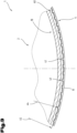
- Fig. 4 is the cut 13 to form the previously in the Fig. 1 to 3 described outer part 12 in its undeformed, flat position, whereby the same reference numerals or component designations are used for the same parts as in the previous Fig. 1 to 3 To avoid unnecessary repetition, please refer to the detailed description in the previous Fig. 1 to 3 pointed out or referred to.
- the previously described predetermined separation area 22 is not shown in detail here, but can also be provided as previously described as a possible and optional variant. Furthermore, the orientation of the individual support elements 41, starting from the first end face 19 facing the ground and moving toward the second end face 20, is more clearly visible here. Due to the arcuately curved longitudinal profile of the two end faces 19, 20 and their common center (center of the radius), the individual support elements 41 also have a longitudinal profile aligned toward the center.
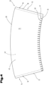
- FIG. 5 and 6 a further and possibly independent embodiment of the outer part 12 formed from the blank 13 to the jacket is shown, wherein again the same reference numerals or component designations are used for the same parts as in the previous Fig. 1 to 4 To avoid unnecessary repetition, to the detailed description in the previous Fig. 1 to 4 pointed out or referred to.
- the blank 13 and the outer part 12 formed therefrom in turn comprise the additional support device 40, which, however, has a different design than the previously described embodiment.
- the additional support device 40 comprises at least one forming section 46, which is also molded into the material of the blank 13.
- the at least one forming section 46 is formed starting from the inner surface 43 of the outer part 12 in the direction of its outer surface 42.
- the at least one forming section 46 is arranged at a distance from the first end face 19 in the direction of the opposite second end face 20.
- the at least one forming section 46 can have a longitudinal profile that is mostly curved outward. Adjacent to the at least one forming section 46, an end section 47 is provided in the direction of the first end face 19. Thus, a corresponding end section 47 is also formed or arranged adjacent to each forming section 46. The end section 47 can, in turn, be oriented so as to extend at an angle toward the longitudinal axis 8.
- the at least one forming section 46 can have a parallel longitudinal extension with respect to the first end face 19. It is also possible for the forming section 46 to be arranged or formed to run continuously along the first end face 19 in the circumferential direction. Irrespective of this, it would also be conceivable for a plurality of forming sections 46 to be provided and for the forming sections 46 to be arranged spaced apart from one another along the first end face 19 in the circumferential direction.
- the at least one support element 41 defines in the upright position of the blank 13 to the outer part 12, in turn, the clear inner dimension 44, which is smaller than an inner dimension 45 of the outer part 12 in its undeformed configuration without the forming section 46.
- the bottom end of the outer part 12 is shown in the undeformed position in dashed lines in the Fig. 6 still hinted at.
- the forming section 46 Due to the formation and shaping of the forming section 46, it may be necessary to make the undeformed height between the first and second end faces 19, 20 somewhat longer in order to subsequently achieve support on the shoulder 11 on the one hand and to be able to cover the container shell 4 up to the flange 6 immediately adjacent thereto on the other hand.
- an adhesive or bonding agent is preferably used in the overlapping area 16 to be formed.
- This adhesive can be applied to one of the end sections 14 or 15 or to both of them, as is well known.
- the inner container 2 is usually made of a plastic or a degradable material that can be formed in a thermoforming process.
- the outer part 12 is preferably made of a cellulose material.
- the blank 13 can also be provided with a printed image on at least one of its flat sides, namely the outer surface 42 and/or the inner surface 43.
- the adhesive used in the overlapping area 16 has different adhesive force values depending on the direction of force acting on it, in particular the separation direction.
- the adhesive should have a sufficiently high adhesive force value to ensure sufficient mutual hold of the two end sections 14, 15 to one another under normal loads.
- the adhesive has a second adhesive force value which is different from the first adhesive force value.
- the first adhesive force value should be greater than the second adhesive force value.
- the compressive force -F- can be applied to the combination packaging container 1 in a wide variety of directions and is at least partially converted into a separation force which at least partially separates the overlapping region 16. In this case, the second adhesive force value is exceeded and the two end sections 14, 15, initially held together by the adhesive or adhesive, separate from each other, at least in sections.
- compression can be performed in the radial and/or axial directions. This spatially deforms the entire combination packaging container 1.
- a compressive force -F- is applied in the axial direction, the outer part 12 and also the container shell 4 bend in the direction of the longitudinal axis 8. Due to the lower adhesive force value in this force direction, the separation of the overlapping area 16 can be carried out or carried out.
- the sleeve-shaped outer part 12 can be supported even better and more securely in the axial direction on the shoulder 11 of the inner container 2 by means of its additional support device 40, without the need for an additional adhesive.
- the adhesive point previously provided for safety reasons between the inner surface 43 of the outer part 12 and the container shell 4 can thus be omitted and no longer needs to be provided.
- an unwanted adhesive connection between the outer part 12 and the inner container 2 can be avoided.
- the separation process of the target separation area 22 is then carried out during collection and/or during waste disposal, carried out mechanically by means of a press or a squeezing device.
- the combination packaging container on a support surface, either with its closed end or with the open end of the inner container, and then apply the compressive force -F- to the end facing away from the support surface in the direction of the support surface.
- the compressive force can be easily applied to the combination packaging container and introduced into it, e.g., using human force. The risk of injury can be minimized with an arrangement in which the compressive force is applied to the floor.
- the compressive force -F- on the combination packaging container in a parallel orientation with respect to a longitudinal axis extending between the open end and the closed end, or in an orientation angular to the longitudinal axis.
- the compressive force can be easily redirected, at least for the most part, into a tearing force acting in a predominantly radial direction, which leads to the outer part bursting open in its overlapping area. If the force application direction deviates from this, the spatial deformation can also cause the overlapping area to separate.
- the separation process of the combination packaging container 1 into its various components can be carried out either by a single person or during the collection and disposal process.
Landscapes
- Engineering & Computer Science (AREA)
- Mechanical Engineering (AREA)
- Ceramic Engineering (AREA)
- Packages (AREA)
- Cartons (AREA)
- Making Paper Articles (AREA)
- Wrappers (AREA)
Claims (13)
- Récipient d'emballage combiné (1) comprenant un récipient intérieur (2) en forme de gobelet avec une enveloppe de récipient (4), un fond (3), une bride (6), une contre-dépouille (10) se trouvant dans la zone de fond de l'enveloppe de récipient (4), le récipient intérieur (2) présentant, dans la zone de transition directe entre le fond (3) et l'enveloppe de récipient (4), un épaulement (11) ou un renflement faisant saillie sur le côté opposé à l'axe longitudinal (8) ainsi qu'une partie extérieure (12) en forme de manchette entourant au moins localement le récipient intérieur (2) sur son enveloppe de récipient (4),- la partie extérieure (12) étant formée d'une pièce découpée (13), laquelle pièce découpée (13) est enroulée dans son état redressé pour former une enveloppe, et une première section d'extrémité (14) et une deuxième section d'extrémité (15) de l'enveloppe tournée vers celle-ci étant alors reliées entre elles dans une zone de chevauchement (16),- la partie extérieure (12) présentant en outre une première face frontale (19) et une deuxième face frontale (20), les deux faces frontales (19, 20) étant espacées l'une de l'autre et définissant, à l'état redressé, une hauteur de construction (21) de l'enveloppe avec un axe longitudinal (8) s'étendant en direction de la hauteur de construction (21), la première face frontale (19) définissant au moins par sections une zone d'appui et la première face frontale (19) pouvant en outre être tournée vers le fond (3) et la deuxième face frontale (20) vers l'extrémité ouverte (5) du récipient intérieur (2), dans lequel la partie extérieure (12) en forme de manchette s'appuie avec sa première face frontale (19) tournée vers le fond (3) du récipient intérieur (2) sur cet épaulement (11) formé dans la zone de transition,
caractérisé en ce que- il est prévu sur la partie extérieure (12) un dispositif d'appui supplémentaire (40), lequel dispositif d'appui supplémentaire (40) est agencé ou formé dans la zone de la première face frontale (19) de la partie extérieure (12) formée à partir de la pièce découpée (13), et- le dispositif d'appui supplémentaire (40) définit une dimension intérieure de la partie intérieure (44) qui est inférieure à une dimension intérieure (45) de la partie extérieure (12) dans sa configuration non déformée dans la zone de la première face frontale (19). - Récipient d'emballage combiné (1) selon la revendication 1, caractérisé en ce que le dispositif d'appui supplémentaire (40) comprend au moins un élément d'appui (41) et ledit au moins un élément d'appui (41) définit la dimension intérieure de la partie intérieure (44).
- Récipient d'emballage combiné (1) selon la revendication 2, caractérisé en ce que l'au moins un élément d'appui (41) est formé dans le matériau de la pièce découpée (13) en partant d'une surface extérieure (42) de la partie extérieure (12) en direction d'une surface intérieure (43) et fait saillie en direction radiale au-delà de la surface intérieure non formée (43) en direction de l'axe longitudinal (8).
- Récipient d'emballage combiné (1) selon la revendication 2 ou 3, caractérisé en ce que l'au moins un élément d'appui (41) présente une extension longitudinale partant de la première face frontale (19) en direction de la deuxième face frontale (20).
- Récipient d'emballage combiné (1) selon l'une des revendications 2 à 4, caractérisé en ce que plusieurs éléments d'appui (41) sont prévus et en ce que les éléments d'appui (41) sont espacés les uns des autres le long de la première face frontale (19) dans la direction circonférentielle.
- Récipient d'emballage combiné (1) selon la revendication 1, caractérisé en ce que le dispositif d'appui supplémentaire (40) comprend au moins une section de formage (46), laquelle au moins une section de formage (46) est formée dans le matériau de la pièce découpée (13) en partant d'une surface intérieure (43) de la partie extérieure (12) en direction d'une surface extérieure (42) et l'au moins une section de formage (46) est agencée à distance de la première face frontale (19).
- Récipient d'emballage combiné (1) selon la revendication 6, caractérisé en ce que l'au moins une section de formage (46) présente, vu en coupe axiale, un tracé longitudinal réalisé de préférence de manière incurvée et qu'une section d'extrémité (47) se raccordant à la section de formage (46) en direction de la première face frontale (19) est orienté de manière inclinée en direction de l'axe longitudinal (8).
- Récipient d'emballage combiné (1) selon la revendication 6 ou 7, caractérisé en ce que l'au moins une section de formage (46) présente un tracé longitudinal parallèle par rapport à la première face frontale (19).
- Récipient d'emballage combiné (1) selon l'une des revendications 6 à 8, caractérisé en ce que la section de formage (46) est agencée de manière continue dans la direction circonférentielle le long de la première face frontale (19).
- Récipient d'emballage combiné (1) selon l'une des revendications 6 à 8, caractérisé en ce qu'il est prévu plusieurs sections de formage (46) et en ce que les sections de formage (46) sont agencées à distance les unes des autres le long de la première face frontale (19) dans la direction circonférentielle.
- Récipient d'emballage combiné (1) selon l'une des revendications précédentes, caractérisé en ce qu'un agent adhésif est prévu dans la zone de chevauchement (16) entre les deux sections d'extrémité (14, 15), lequel agent adhésif présente une première valeur de force d'adhérence vue dans la direction circonférentielle et une deuxième valeur de force d'adhérence vue dans la direction radiale, la première valeur de force d'adhérence étant supérieure à la deuxième valeur de force d'adhérence.
- Récipient d'emballage combiné (1) selon l'une des revendications précédentes, caractérisé en ce qu'au moins une zone de séparation théorique (22) est formée ou prévue dans l'enveloppe de la partie extérieure (12).
- Récipient d'emballage combiné (1) selon la revendication 1, caractérisé en ce que la partie extérieure (12) en forme de manchette est soutenue axialement contre l'épaulement (11) du récipient intérieur (2) au moyen de son dispositif d'appui supplémentaire (40), à l'exclusion d'un moyen adhésif supplémentaire.
Priority Applications (1)
| Application Number | Priority Date | Filing Date | Title |
|---|---|---|---|
| RS20250469A RS66794B1 (sr) | 2021-02-25 | 2022-02-23 | Spoljni deo u obliku manžetne i kombinovani kontejner za pakovanje opremljen njime i postupak odvajanja kombinovanog kontejnera za pakovanje |
Applications Claiming Priority (2)
| Application Number | Priority Date | Filing Date | Title |
|---|---|---|---|
| ATA50131/2021A AT524230B1 (de) | 2021-02-25 | 2021-02-25 | Manschettenförmiges Außenteil, damit ausgestatteter Kombi-Verpackungsbehälter und Verfahren zum Trennen des Kombi-Verpackungsbehälters |
| PCT/EP2022/054493 WO2022180078A1 (fr) | 2021-02-25 | 2022-02-23 | Partie externe en forme de manchon, récipient d'emballage combiné équipé de celle-ci, et procédé de séparation du récipient d'emballage combiné |
Publications (3)
| Publication Number | Publication Date |
|---|---|
| EP4298024A1 EP4298024A1 (fr) | 2024-01-03 |
| EP4298024C0 EP4298024C0 (fr) | 2025-04-16 |
| EP4298024B1 true EP4298024B1 (fr) | 2025-04-16 |
Family
ID=80628879
Family Applications (1)
| Application Number | Title | Priority Date | Filing Date |
|---|---|---|---|
| EP22707701.3A Active EP4298024B1 (fr) | 2021-02-25 | 2022-02-23 | Partie externe en forme de manchon, récipient d'emballage combiné équipé de celle-ci, et procédé de séparation du récipient d'emballage combiné |
Country Status (8)
| Country | Link |
|---|---|
| US (1) | US20240124193A1 (fr) |
| EP (1) | EP4298024B1 (fr) |
| AT (2) | AT524230B1 (fr) |
| CA (1) | CA3211076A1 (fr) |
| HU (1) | HUE072441T2 (fr) |
| PL (1) | PL4298024T3 (fr) |
| RS (1) | RS66794B1 (fr) |
| WO (1) | WO2022180078A1 (fr) |
Families Citing this family (1)
| Publication number | Priority date | Publication date | Assignee | Title |
|---|---|---|---|---|
| DE102023108207A1 (de) * | 2023-03-30 | 2024-10-02 | W. U. H. Fernholz Gmbh & Co Kg | Verpackungsbehälter |
Citations (2)
| Publication number | Priority date | Publication date | Assignee | Title |
|---|---|---|---|---|
| WO2008045944A2 (fr) * | 2006-10-12 | 2008-04-17 | Huhtamaki Consumer Packaging, Inc. | Récipient à parois multiples et procédé |
| GB2469200A (en) * | 2009-04-01 | 2010-10-06 | Rundpack Ag | A beaker shaped container and method of producing |
Family Cites Families (24)
| Publication number | Priority date | Publication date | Assignee | Title |
|---|---|---|---|---|
| FR2108873A1 (en) * | 1970-10-14 | 1972-05-26 | Lebocey Industrie | Yogurt cartons mfr - by thermoforming walls and top in one piece |
| CH678938A5 (fr) | 1989-07-14 | 1991-11-29 | Sandherr Packungen Ag | |
| US5385260A (en) * | 1994-01-19 | 1995-01-31 | Sherwood Industries, Inc. | Disposable cup assembly system and method |
| CH690431A5 (de) | 1996-09-26 | 2000-09-15 | Sandherr Packungen Ag | Verfahren zum Herstellen eines becherförmigen Kombi-Verpackungsbehälters sowie Kunststoffinnenteil für ein solches Verfahren. |
| DE29714534U1 (de) * | 1997-08-14 | 1998-12-17 | Gizeh Verpackungen GmbH & Co. KG, 51702 Bergneustadt | Becher |
| JPH11157525A (ja) * | 1997-11-27 | 1999-06-15 | Keiichi Tokunaga | 容 器 |
| CH693611A5 (de) * | 1999-10-07 | 2003-11-14 | Sandherr Packungen Ag | Konischer Verpackungsbehälter. |
| AU2003215535A1 (en) | 2002-01-10 | 2003-07-24 | Rundpack Ag | Method for producing a combined packing container and a device for carrying out said method |
| DE202004015374U1 (de) * | 2004-10-04 | 2006-02-09 | Zott Gmbh & Co. Kg | Behälter für Lebensmittel |
| US20080087677A1 (en) * | 2006-10-12 | 2008-04-17 | Robertson Ronald D | Multi walled container and method |
| DE102008005403A1 (de) * | 2008-01-21 | 2009-07-23 | Ptm Packaging Tools Machinery Pte.Ltd. | Becher aus einem Papiermaterial |
| US20090214837A1 (en) * | 2008-02-21 | 2009-08-27 | Multi-Color Corporation | Insulating Label |
| AT506750B1 (de) | 2008-04-24 | 2011-02-15 | Rundpack Ag | Verfahren zur herstellung eines kombi - verpackungsbehälters sowie einem mantelförmigen aussenteil |
| DE102008026984A1 (de) * | 2008-05-28 | 2009-12-03 | Ptm Packaging Tools Machinery Pte.Ltd. | Außenmantel für einen doppelwandigen Becher und Verfahren zum Herstellen |
| US20100181328A1 (en) * | 2009-01-16 | 2010-07-22 | Cook Matthew R | Protective sleeve |
| JP2011025958A (ja) * | 2009-07-24 | 2011-02-10 | Tomei Kagaku Kogyo Kk | 外装体及び複合容器 |
| DE102009060333A1 (de) | 2009-12-23 | 2011-06-30 | Optipack GmbH, 86850 | Verpackungsbehälter |
| US20120205430A1 (en) * | 2011-02-14 | 2012-08-16 | Dickert James C | Disposable insulated container and method of making |
| DE102011014844A1 (de) * | 2011-03-23 | 2012-09-27 | Optipack Gmbh | Behälter mit Banderole |
| US8608018B2 (en) * | 2012-05-21 | 2013-12-17 | Meadwestvaco Corporation | Insulated container with comfort zone |
| US11059653B2 (en) * | 2016-04-13 | 2021-07-13 | IMEX Vision, LLC | Insulating cup |
| CN109625521B (zh) * | 2019-01-17 | 2024-12-13 | 湖北克拉弗特实业有限公司 | 一种双层容器 |
| AT522907B1 (de) * | 2019-06-07 | 2021-04-15 | Greiner Packaging Ag | Manschettenförmiges Außenteil sowie damit ausgestatteter Kombi-Verpackungsbehälter |
| US20240327054A1 (en) | 2021-02-25 | 2024-10-03 | Greiner Packaging Ag | Sleeve-shaped outer part, combination packaging container equippedtherewith, and method for separating the combination packaging container |
-
2021
- 2021-02-25 AT ATA50131/2021A patent/AT524230B1/de active
- 2021-09-20 AT ATA50737/2021A patent/AT524826B1/de active
-
2022
- 2022-02-23 RS RS20250469A patent/RS66794B1/sr unknown
- 2022-02-23 US US18/278,841 patent/US20240124193A1/en active Pending
- 2022-02-23 CA CA3211076A patent/CA3211076A1/fr active Pending
- 2022-02-23 WO PCT/EP2022/054493 patent/WO2022180078A1/fr not_active Ceased
- 2022-02-23 EP EP22707701.3A patent/EP4298024B1/fr active Active
- 2022-02-23 PL PL22707701.3T patent/PL4298024T3/pl unknown
- 2022-02-23 HU HUE22707701A patent/HUE072441T2/hu unknown
Patent Citations (2)
| Publication number | Priority date | Publication date | Assignee | Title |
|---|---|---|---|---|
| WO2008045944A2 (fr) * | 2006-10-12 | 2008-04-17 | Huhtamaki Consumer Packaging, Inc. | Récipient à parois multiples et procédé |
| GB2469200A (en) * | 2009-04-01 | 2010-10-06 | Rundpack Ag | A beaker shaped container and method of producing |
Also Published As
| Publication number | Publication date |
|---|---|
| CA3211076A1 (fr) | 2022-09-01 |
| AT524230A4 (de) | 2022-04-15 |
| EP4298024A1 (fr) | 2024-01-03 |
| AT524826A2 (de) | 2022-09-15 |
| PL4298024T3 (pl) | 2025-08-25 |
| AT524826A3 (de) | 2023-06-15 |
| AT524230B1 (de) | 2022-04-15 |
| AT524826B1 (de) | 2023-10-15 |
| US20240124193A1 (en) | 2024-04-18 |
| EP4298024C0 (fr) | 2025-04-16 |
| RS66794B1 (sr) | 2025-06-30 |
| HUE072441T2 (hu) | 2025-11-28 |
| WO2022180078A1 (fr) | 2022-09-01 |
Similar Documents
| Publication | Publication Date | Title |
|---|---|---|
| EP4265536B1 (fr) | Pièce externe en forme de manchette ainsi que conteneur d'emballage combiné muni de celle-ci et procédé de séparation du conteneur d'emballage combiné | |
| EP4298025B1 (fr) | Pièce externe en forme de manchon et contenant d'emballage combiné muni de celle-ci, et procédé pour séparer le contenant d'emballage combiné | |
| AT508081B1 (de) | Kombi-verpackungsbehälter sowie verfahren zu dessen herstellung | |
| AT506750B1 (de) | Verfahren zur herstellung eines kombi - verpackungsbehälters sowie einem mantelförmigen aussenteil | |
| EP4298024B1 (fr) | Partie externe en forme de manchon, récipient d'emballage combiné équipé de celle-ci, et procédé de séparation du récipient d'emballage combiné | |
| EP2838807B1 (fr) | Récipient d'emballage combiné | |
| AT513804B1 (de) | Verfahren zur Herstellung eines Kombi-Verpackungsbehälters sowie Kombi-Verpackungsbehälter | |
| AT526366B1 (de) | Zuschnitt, sowie aus einem Zuschnitt gebildetes manschettenförmiges Außenteil zum Ummanteln eines becherförmigen Innenbehälters, sowie Kombi-Verpackungsbehälter | |
| EP3107817B1 (fr) | Couvercle de fermeture muni d'une garantie d'inviolabilité et unité d'emballage munie dudit couvercle | |
| AT526840B1 (de) | Kombi-Verpackungsbehälter mit einem Behälter und einem Außenteil | |
| EP3730418B1 (fr) | Récipient | |
| AT506749A1 (de) | Verfahren zur herstellung eines kombi-verpackungsbehälters | |
| AT507739B1 (de) | Verfahren zur herstellung eines kombi - verpackungsbehälters | |
| AT504479B1 (de) | Kombi-verpackungsbehälter |
Legal Events
| Date | Code | Title | Description |
|---|---|---|---|
| STAA | Information on the status of an ep patent application or granted ep patent |
Free format text: STATUS: UNKNOWN |
|
| STAA | Information on the status of an ep patent application or granted ep patent |
Free format text: STATUS: THE INTERNATIONAL PUBLICATION HAS BEEN MADE |
|
| PUAI | Public reference made under article 153(3) epc to a published international application that has entered the european phase |
Free format text: ORIGINAL CODE: 0009012 |
|
| STAA | Information on the status of an ep patent application or granted ep patent |
Free format text: STATUS: REQUEST FOR EXAMINATION WAS MADE |
|
| 17P | Request for examination filed |
Effective date: 20230921 |
|
| AK | Designated contracting states |
Kind code of ref document: A1 Designated state(s): AL AT BE BG CH CY CZ DE DK EE ES FI FR GB GR HR HU IE IS IT LI LT LU LV MC MK MT NL NO PL PT RO RS SE SI SK SM TR |
|
| DAV | Request for validation of the european patent (deleted) | ||
| DAX | Request for extension of the european patent (deleted) | ||
| GRAP | Despatch of communication of intention to grant a patent |
Free format text: ORIGINAL CODE: EPIDOSNIGR1 |
|
| STAA | Information on the status of an ep patent application or granted ep patent |
Free format text: STATUS: GRANT OF PATENT IS INTENDED |
|
| INTG | Intention to grant announced |
Effective date: 20241014 |
|
| TPAC | Observations filed by third parties |
Free format text: ORIGINAL CODE: EPIDOSNTIPA |
|
| GRAS | Grant fee paid |
Free format text: ORIGINAL CODE: EPIDOSNIGR3 |
|
| GRAA | (expected) grant |
Free format text: ORIGINAL CODE: 0009210 |
|
| STAA | Information on the status of an ep patent application or granted ep patent |
Free format text: STATUS: THE PATENT HAS BEEN GRANTED |
|
| AK | Designated contracting states |
Kind code of ref document: B1 Designated state(s): AL AT BE BG CH CY CZ DE DK EE ES FI FR GB GR HR HU IE IS IT LI LT LU LV MC MK MT NL NO PL PT RO RS SE SI SK SM TR |
|
| REG | Reference to a national code |
Ref country code: GB Ref legal event code: FG4D Free format text: NOT ENGLISH |
|
| REG | Reference to a national code |
Ref country code: CH Ref legal event code: EP |
|
| REG | Reference to a national code |
Ref country code: IE Ref legal event code: FG4D Free format text: LANGUAGE OF EP DOCUMENT: GERMAN |
|
| REG | Reference to a national code |
Ref country code: DE Ref legal event code: R096 Ref document number: 502022003597 Country of ref document: DE |
|
| U01 | Request for unitary effect filed |
Effective date: 20250507 |
|
| U07 | Unitary effect registered |
Designated state(s): AT BE BG DE DK EE FI FR IT LT LU LV MT NL PT RO SE SI Effective date: 20250513 |
|
| PG25 | Lapsed in a contracting state [announced via postgrant information from national office to epo] |
Ref country code: ES Free format text: LAPSE BECAUSE OF FAILURE TO SUBMIT A TRANSLATION OF THE DESCRIPTION OR TO PAY THE FEE WITHIN THE PRESCRIBED TIME-LIMIT Effective date: 20250416 |
|
| PG25 | Lapsed in a contracting state [announced via postgrant information from national office to epo] |
Ref country code: GR Free format text: LAPSE BECAUSE OF FAILURE TO SUBMIT A TRANSLATION OF THE DESCRIPTION OR TO PAY THE FEE WITHIN THE PRESCRIBED TIME-LIMIT Effective date: 20250717 |
|
| PG25 | Lapsed in a contracting state [announced via postgrant information from national office to epo] |
Ref country code: HR Free format text: LAPSE BECAUSE OF FAILURE TO SUBMIT A TRANSLATION OF THE DESCRIPTION OR TO PAY THE FEE WITHIN THE PRESCRIBED TIME-LIMIT Effective date: 20250416 |
|
| PG25 | Lapsed in a contracting state [announced via postgrant information from national office to epo] |
Ref country code: IS Free format text: LAPSE BECAUSE OF FAILURE TO SUBMIT A TRANSLATION OF THE DESCRIPTION OR TO PAY THE FEE WITHIN THE PRESCRIBED TIME-LIMIT Effective date: 20250816 |
|
| REG | Reference to a national code |
Ref country code: HU Ref legal event code: AG4A Ref document number: E072441 Country of ref document: HU |
|
| PG25 | Lapsed in a contracting state [announced via postgrant information from national office to epo] |
Ref country code: SM Free format text: LAPSE BECAUSE OF FAILURE TO SUBMIT A TRANSLATION OF THE DESCRIPTION OR TO PAY THE FEE WITHIN THE PRESCRIBED TIME-LIMIT Effective date: 20250416 |
|
| PG25 | Lapsed in a contracting state [announced via postgrant information from national office to epo] |
Ref country code: SK Free format text: LAPSE BECAUSE OF FAILURE TO SUBMIT A TRANSLATION OF THE DESCRIPTION OR TO PAY THE FEE WITHIN THE PRESCRIBED TIME-LIMIT Effective date: 20250416 |
|
| PLBE | No opposition filed within time limit |
Free format text: ORIGINAL CODE: 0009261 |
|
| STAA | Information on the status of an ep patent application or granted ep patent |
Free format text: STATUS: NO OPPOSITION FILED WITHIN TIME LIMIT |
|
| REG | Reference to a national code |
Ref country code: CH Ref legal event code: L10 Free format text: ST27 STATUS EVENT CODE: U-0-0-L10-L00 (AS PROVIDED BY THE NATIONAL OFFICE) Effective date: 20260225 |
|
| PGFP | Annual fee paid to national office [announced via postgrant information from national office to epo] |
Ref country code: HU Payment date: 20260220 Year of fee payment: 5 |
|
| U20 | Renewal fee for the european patent with unitary effect paid |
Year of fee payment: 5 Effective date: 20260210 |
|
| 26N | No opposition filed |
Effective date: 20260119 |
|
| PGFP | Annual fee paid to national office [announced via postgrant information from national office to epo] |
Ref country code: GB Payment date: 20260224 Year of fee payment: 5 |
|
| PGFP | Annual fee paid to national office [announced via postgrant information from national office to epo] |
Ref country code: NO Payment date: 20260226 Year of fee payment: 5 Ref country code: IE Payment date: 20260225 Year of fee payment: 5 |
|
| REG | Reference to a national code |
Ref country code: CH Ref legal event code: U11 Free format text: ST27 STATUS EVENT CODE: U-0-0-U10-U11 (AS PROVIDED BY THE NATIONAL OFFICE) Effective date: 20260416 |
|
| PGFP | Annual fee paid to national office [announced via postgrant information from national office to epo] |
Ref country code: RS Payment date: 20260116 Year of fee payment: 5 |
|
| PGFP | Annual fee paid to national office [announced via postgrant information from national office to epo] |
Ref country code: TR Payment date: 20260114 Year of fee payment: 5 |