EP4297946B1 - Verfahren zur versorgung einer giessvorrichtung mit polymerisierbarem gemisch und zugehörige versorgungsvorrichtung - Google Patents
Verfahren zur versorgung einer giessvorrichtung mit polymerisierbarem gemisch und zugehörige versorgungsvorrichtung Download PDFInfo
- Publication number
- EP4297946B1 EP4297946B1 EP22708139.5A EP22708139A EP4297946B1 EP 4297946 B1 EP4297946 B1 EP 4297946B1 EP 22708139 A EP22708139 A EP 22708139A EP 4297946 B1 EP4297946 B1 EP 4297946B1
- Authority
- EP
- European Patent Office
- Prior art keywords
- tank
- pressure
- polymerizable mixture
- inlet
- set value
- Prior art date
- Legal status (The legal status is an assumption and is not a legal conclusion. Google has not performed a legal analysis and makes no representation as to the accuracy of the status listed.)
- Active
Links
Images
Classifications
-
- B—PERFORMING OPERATIONS; TRANSPORTING
- B29—WORKING OF PLASTICS; WORKING OF SUBSTANCES IN A PLASTIC STATE IN GENERAL
- B29D—PRODUCING PARTICULAR ARTICLES FROM PLASTICS OR FROM SUBSTANCES IN A PLASTIC STATE
- B29D11/00—Producing optical elements, e.g. lenses or prisms
- B29D11/00009—Production of simple or compound lenses
- B29D11/00038—Production of contact lenses
-
- B—PERFORMING OPERATIONS; TRANSPORTING
- B29—WORKING OF PLASTICS; WORKING OF SUBSTANCES IN A PLASTIC STATE IN GENERAL
- B29C—SHAPING OR JOINING OF PLASTICS; SHAPING OF MATERIAL IN A PLASTIC STATE, NOT OTHERWISE PROVIDED FOR; AFTER-TREATMENT OF THE SHAPED PRODUCTS, e.g. REPAIRING
- B29C31/00—Handling, e.g. feeding of the material to be shaped, storage of plastics material before moulding; Automation, i.e. automated handling lines in plastics processing plants, e.g. using manipulators or robots
- B29C31/04—Feeding of the material to be moulded, e.g. into a mould cavity
-
- B—PERFORMING OPERATIONS; TRANSPORTING
- B29—WORKING OF PLASTICS; WORKING OF SUBSTANCES IN A PLASTIC STATE IN GENERAL
- B29C—SHAPING OR JOINING OF PLASTICS; SHAPING OF MATERIAL IN A PLASTIC STATE, NOT OTHERWISE PROVIDED FOR; AFTER-TREATMENT OF THE SHAPED PRODUCTS, e.g. REPAIRING
- B29C37/00—Component parts, details, accessories or auxiliary operations, not covered by group B29C33/00 or B29C35/00
- B29C37/006—Degassing moulding material or draining off gas during moulding
-
- B—PERFORMING OPERATIONS; TRANSPORTING
- B29—WORKING OF PLASTICS; WORKING OF SUBSTANCES IN A PLASTIC STATE IN GENERAL
- B29C—SHAPING OR JOINING OF PLASTICS; SHAPING OF MATERIAL IN A PLASTIC STATE, NOT OTHERWISE PROVIDED FOR; AFTER-TREATMENT OF THE SHAPED PRODUCTS, e.g. REPAIRING
- B29C39/00—Shaping by casting, i.e. introducing the moulding material into a mould or between confining surfaces without significant moulding pressure; Apparatus therefor
- B29C39/22—Component parts, details or accessories; Auxiliary operations
- B29C39/24—Feeding the material into the mould
-
- B—PERFORMING OPERATIONS; TRANSPORTING
- B29—WORKING OF PLASTICS; WORKING OF SUBSTANCES IN A PLASTIC STATE IN GENERAL
- B29C—SHAPING OR JOINING OF PLASTICS; SHAPING OF MATERIAL IN A PLASTIC STATE, NOT OTHERWISE PROVIDED FOR; AFTER-TREATMENT OF THE SHAPED PRODUCTS, e.g. REPAIRING
- B29C39/00—Shaping by casting, i.e. introducing the moulding material into a mould or between confining surfaces without significant moulding pressure; Apparatus therefor
- B29C39/22—Component parts, details or accessories; Auxiliary operations
- B29C39/42—Casting under special conditions, e.g. vacuum
-
- B—PERFORMING OPERATIONS; TRANSPORTING
- B29—WORKING OF PLASTICS; WORKING OF SUBSTANCES IN A PLASTIC STATE IN GENERAL
- B29C—SHAPING OR JOINING OF PLASTICS; SHAPING OF MATERIAL IN A PLASTIC STATE, NOT OTHERWISE PROVIDED FOR; AFTER-TREATMENT OF THE SHAPED PRODUCTS, e.g. REPAIRING
- B29C39/00—Shaping by casting, i.e. introducing the moulding material into a mould or between confining surfaces without significant moulding pressure; Apparatus therefor
- B29C39/22—Component parts, details or accessories; Auxiliary operations
- B29C39/44—Measuring, controlling or regulating
-
- B—PERFORMING OPERATIONS; TRANSPORTING
- B29—WORKING OF PLASTICS; WORKING OF SUBSTANCES IN A PLASTIC STATE IN GENERAL
- B29D—PRODUCING PARTICULAR ARTICLES FROM PLASTICS OR FROM SUBSTANCES IN A PLASTIC STATE
- B29D11/00—Producing optical elements, e.g. lenses or prisms
- B29D11/00009—Production of simple or compound lenses
- B29D11/00038—Production of contact lenses
- B29D11/00125—Auxiliary operations, e.g. removing oxygen from the mould, conveying moulds from a storage to the production line in an inert atmosphere
-
- B—PERFORMING OPERATIONS; TRANSPORTING
- B29—WORKING OF PLASTICS; WORKING OF SUBSTANCES IN A PLASTIC STATE IN GENERAL
- B29C—SHAPING OR JOINING OF PLASTICS; SHAPING OF MATERIAL IN A PLASTIC STATE, NOT OTHERWISE PROVIDED FOR; AFTER-TREATMENT OF THE SHAPED PRODUCTS, e.g. REPAIRING
- B29C2791/00—Shaping characteristics in general
- B29C2791/004—Shaping under special conditions
- B29C2791/005—Using a particular environment, e.g. sterile fluids other than air
-
- B—PERFORMING OPERATIONS; TRANSPORTING
- B29—WORKING OF PLASTICS; WORKING OF SUBSTANCES IN A PLASTIC STATE IN GENERAL
- B29C—SHAPING OR JOINING OF PLASTICS; SHAPING OF MATERIAL IN A PLASTIC STATE, NOT OTHERWISE PROVIDED FOR; AFTER-TREATMENT OF THE SHAPED PRODUCTS, e.g. REPAIRING
- B29C2791/00—Shaping characteristics in general
- B29C2791/004—Shaping under special conditions
- B29C2791/006—Using vacuum
-
- B—PERFORMING OPERATIONS; TRANSPORTING
- B29—WORKING OF PLASTICS; WORKING OF SUBSTANCES IN A PLASTIC STATE IN GENERAL
- B29L—INDEXING SCHEME ASSOCIATED WITH SUBCLASS B29C, RELATING TO PARTICULAR ARTICLES
- B29L2011/00—Optical elements, e.g. lenses, prisms
- B29L2011/0016—Lenses
Definitions
- the invention belongs to the field of molding.
- the invention more precisely relates to a method for supplying at least a molding device with a polymerizable mixture.
- the invention also relates to a supply device for supplying at least a molding device with a polymerizable mixture.
- the invention finds particularly advantageous, but not exclusive, application for the manufacturing of transparent optical articles such as ophthalmic lenses, and notably lenses for spectacles and sunglasses or vision correcting spectacles.
- any gas can thus be dissolved in the polymerizable mixture and may result in bubbles trapped inside the final molded article, said molded article being then considered as defective.
- any gas either already present in the tank or newly generated (due for example to the presence of water), can be dissolved in the polymerizable mixture before the supply of the molding device and therefore induce a defective molded article.
- Document EP0118073A1 describes a method and apparatus for casting a resin around a metal body, within a mold.
- One object of the invention is to provide a method for supplying a polymerizable mixture that allows reducing the quantity of defective molded articles exhibiting bubbles trapped therein.
- a further object of the invention is to provide a method that allows continuously supplying of the molding device in degassed polymerizable mixture.
- Step c) of the method ensures that the polymerizable mixture contained in the tank is subjected to a pressure lower than ambient pressure, not only during the formation of said polymerizable mixture, but also while the molding device is being supplied. Therefore, the method of the invention not only ensures the degassing of the polymerizable mixture before it reaches the molding device, but also prevents any further regassing of the polymerizable mixture before it reaches the molding device, notably the regassing due to chemical reaction, the presence of water, gas trapped in the supply device, or due to any other factor.
- a further object of the invention is to provide a supply device that continuously supplies the molding device in degassed polymerizable mixture.
- the supply device for supplying at least one molding device with a polymerizable mixture according to claim 7.
- the vacuum regulator allows reaching a given pressure in the tank, smaller than ambient pressure, in order to remove the gas from the polymerizable mixture ahead of the supply of the molding device in polymerizable mixture, but also allows maintaining the pressure in the tank at the given value, even during the supplying of the molding device, in order to prevent any regassing of the polymerizable mixture.
- the looping line connected by its two ends to the tank forms a closed loop with the tank in order to allow a continuous supply of the molding device simultaneously with the continuous degassing of the polymerizable mixture contained in the tank.
- the supply device can supply the molding device in polymerizable mixture without stopping as the polymerizable mixture circulates from the tank to the looping line and returns to the tank, as long as there is enough polymerizable mixture in the tank. While continuously circulating in the looping line and returning back to the tank where the polymerizable mixture is under continuously controlled pressure (at the set value of pressure lower than ambient pressure), the polymerizable mixture is prevented from regassing before it is supplied to the molding device.
- the supply device can supply the molding device in polymerizable mixture without stopping as the polymerizable mixture circulates from the tank to the looping line and returns to the tank, as long as there is enough polymerizable mixture in the tank. While continuously circulating in the looping line and returning back to the tank where the polymerizable mixture is under continuously controlled pressure (at the set value of pressure lower than ambient pressure), the polymerizable mixture is prevented from regassing before it is supplied to the molding device.
- upstream and downstream will be used in the direction of fluid flow, in order to locate various elements with respect to one another in the supply device.
- inlet and outlet will be used in the direction of fluid flow in order to describe the elements that can receive fluid from an inlet and discharge it through an outlet.
- a polymerizable mixture is understood to be a mixture of reactants, notably monomers, pre-polymers and/or of polymers that are able to react with one another so as to form a final polymer material. These reactants are known as precursor reactants of the polymerizable mixture.
- the polymerizable mixture may for instance be a mixture of reactants that react at least partially with one another simply by being brought into contact, without necessarily requiring any external stimulation, such as a thermal, photonic, chemical or mechanical stimulation.
- the polymerizable mixture may comprise for instance, in weight relative to the total weight of the polymerizable mixture:
- the monomer A can be for example a diisocyanate.
- the monomer B can be for example a dithiol.
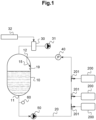
- Figure 1 shows a supply device 100 of the invention for supplying at least one molding device 200 with a polymerizable mixture.
- the at least one molding device 200 comprises at least one mold and a means of injection for injecting the polymerizable mixture inside said mold.
- the molding device 200 is a device for molding ophthalmic lenses. It thus comprises a plurality of molds, each mold being in the shape of a lens.
- the supply device 100 here feeds three molding devices 200 with the same polymerizable mixture.
- Each molding device 200 is plugged on the supply device 100 by a valve 201.
- Each valve 201 is here in the shape of a "T", as commonly used in the field.
- T When the valve 201 is open, the corresponding molding device 200 is connected to the looping line 20.
- the valve 201 is closed, the corresponding molding device 200 is disconnected from the looping line 20.
- connected it is meant in the rest of the description that the elements are in fluidic communication, the fluid being either a liquid or a gas.
- the supply device 100 comprises:
- the polymerizable mixture stored in the tank 10 is preferably a degassed polymerizable mixture, that is to say a polymerizable mixture from which all gases have been removed.
- a degassed polymerizable mixture that is to say a polymerizable mixture from which all gases have been removed.
- Such degassing can for instance occur while the polymerizable mixture is being formed, when mixing its reactants, or just after the polymerizable mixture was formed.
- the looping line 20 is connected, on a first end, to an outlet 11 of the tank 10 for receiving the polymerizable mixture and, on a second end, to an inlet 12 of said tank 10 for returning to the tank 10 an excess in polymerizable mixture.
- the looping line 20 is connected to (respectively disconnected from) an inlet of each of said molding devices 200, by means of the valves 201 in open position (respectively in closed position).
- each of said molding devices 200 forms a dead end, that is to say that once the polymerizable mixture enters the molding device, said polymerizable mixture will not be able to return to the looping line 20.
- the looping line 20 is here a pipe and its first end can be considered as an inlet of said looping line 20, while its second end and the locations where said pipe is connected to the molding devices 200 can be considered as outlets of said looping line 20.
- the polymerizable mixture flows from the tank 10, through the outlet 11 of the tank 10 into the looping line 20, and a part of the polymerizable mixture flows from the looping line 20 into the molding device 200 through the corresponding valve 201, while the rest of the polymerizable mixture (commonly called “excess in polymerizable mixture”) continues to flow in the looping line 20 beyond said valve 201 to go back to the tank 10, through the inlet 12 of the tank 10.
- the outlet 11 of the tank 10 can be provided with a valve (not represented) so that it is possible to close said valve in order to disconnect the looping line 20 from the tank 10 if necessary.
- the supply device 100 also comprises a vacuum regulator 30.
- the vacuum regulator 30 aims at reaching a set value of pressure Ps in the tank 10 and at maintaining the pressure P in the tank 10 at said set value of pressure Ps, even when the molding devices 200 are being supplied in polymerizable mixture through the looping line 20.
- the vacuum regulator 30 is for instance a mechanical vacuum regulator.
- the vacuum regulator 30 is connected to the tank 10. Preferably, it is connected to the tank 10 in a part where the polymerizable mixture cannot get, preferably in the upper part of the tank 10, so that only gases can flow between the vacuum regulator 30 and the tank 10.
- the set value of pressure Ps that is to be reached and maintained in the tank 10 is smaller than the ambient pressure Pam.
- the set value of pressure Ps to be reached in the tank 10 is at least 0.3 bars under the ambient pressure Pam. More preferably, the set value of pressure Ps is between 0.3 to 0.5 bars under the ambient pressure Pam.
- the set value of pressure Ps is preferably comprised in the range [Pam - 0.5; Pam - 0.3], the ambient pressure Pam and the set value of pressure Ps being given in bars.
- the ambient pressure Pam is here defined as the pressure of the atmosphere outside the tank 10.
- Such range of pressure for the set value of pressure Ps prevents the regassing of the polymerizable mixture in the tank 10, while the molding devices 200 are being supplied in degassed polymerizable mixture.
- Such range of pressure for the set value of pressure Ps is a low pressure that is a good compromise, compatible with the higher pressure to which is exposed the degassed polymerizable mixture within the looping line 20 and feed the molding devices 200.
- the set value of pressure Ps is itself a range, instead of being a precise value.
- the set value of pressure Ps is an interval (or range)
- the pressure P is higher than the set value of pressure Ps (P>Ps)
- the pressure P is in fact higher than the upper limit of the range.
- the set value of pressure Ps is an interval (or range)
- the pressure P is lower than, or smaller than, the set value of pressure Ps (P ⁇ Ps)” means that the pressure P is in fact lower than the lower limit of said range.
- the vacuum regulator 30 comprises a pressure sensor to measure the pressure P inside the tank 10.
- the vacuum regulator 30 is designed to control a vacuum pump 31 that is connected to the tank 10 for lowering the pressure P in the tank 10.
- the vacuum regulator 30 is able to measure the pressure P inside the tank 10 and to control the vacuum pump 31 in order to continuously adjust said pressure P inside the tank 10 to the set value of pressure Ps.
- the vacuum pump 31 is connected to the vacuum regulator 30.
- the vacuum pump 31 is connected to the tank 10 through the vacuum regulator 30 that is itself connected to the tank 10.
- the vacuum regulator 30 is able to measure the pressure P inside the tank and to control the vacuum pump 31 in order for it to withdraw some of the gas(es) contained in the tank 10 whenever said pressure P is higher than the set value of pressure Ps.
- the supply device 100 of the invention thus prevents regassing of the polymerizable mixture, that is to say prevents some gas to be dissolved in the polymerizable mixture once the supply of the molding devices 200 has started.
- the regassing is for instance caused by leaks of the looping line 20, trapped gas in the looping line 20, pump cavitation or even chemical reactions.
- the supply device 100 of the invention the polymerizable mixture is degassed before it starts to flow in the looping line 20, but also each time it reaches the tank 10 after it flew in the looping line 20.
- the potential regassing of the polymerizable mixture is prevented because the pressure in the tank 10 is continuously controlled.
- the looping line 20 of the supply device 100 of the invention also comprises, a pump 50, with adjustable speed, for supplying at a set flow rate the inlet of said at least one molding device 200 with the polymerizable mixture from the tank 10.
- the pump 50 eases the flow of polymerizable mixture inside the looping line 20 towards the valves 201 and into the molding devices 200 so that less pressure needs to be applied in the tank 10 for pushing the polymerizable mixture through the outlet of said tank 10.
- the pressurization of the polymerizable mixture in the tank 10 can be lowered without affecting the flow of polymerization in the looping line 20.
- Lowering the pressure P inside the tank 10 lowers the risk of regassing the polymerizable mixture.
- the pressure in the looping line 20, at the inlet of the molding device 200 is maintained at a value higher than the set value of pressure Ps that is maintained in the tank 10.
- the looping line 20 of the supply device 100 of the invention comprises, in addition, a back pressure regulator 40 located downstream of the inlet of the molding device 200 and upstream of the inlet 12 of the tank 10.
- a back pressure regulator 40 located downstream of the inlet of the molding device 200 and upstream of the inlet 12 of the tank 10.
- Such back pressure regulator 40 regulates the pressure at the inlet of said at least one molding device 200.
- the back pressure regulator 40 aims at balancing the pressure in the looping line 20, in order for the molding devices 200 to be fully filled. It therefore prevents the introduction of air inside the molds of the molding devices 200.
- the back pressure regulator 40 is designed to act on the flow rate of the polymerizable mixture that returns to the tank 10 through the looping line 20, said flow rate being set based on the pressure in the looping line 20, downstream of the inlet of the molding devices 200.
- the pressure in the looping line 20, upstream of said valve 201 is naturally higher than the pressure in the looping line 20, downstream of said valve 201, because some polymerizable mixture flew into the corresponding molding device 200 and is therefore "missing" in the looping line 20.
- the balance of pressure operated by the back pressure regulator 40 also forces the polymerizable mixture to flow beyond said valves 201, back into the tank 10.
- the supply device 100 of the invention allows maintaining two different pressures in the closed loop: a first pressure in the tank 10, fixed at the set value of pressure Ps, lower than ambient pressure Pam, that prevents regassing of the polymerizable mixture, and a second pressure in the looping line 20, higher than the set value of pressure Ps, usually near ambient pressure Pam or higher than ambient pressure Pam, in order to properly fill the molding devices 200.
- the vacuum regulator 30 is here also designed to control an inert gas supplier 32 connected to the tank 10 for increasing the pressure P in the tank 10.
- the inert gas supplier 32 is connected to the vacuum regulator 30.
- the inert gas supplier 32 is connected to the tank 10 through the vacuum regulator 30 that is itself connected to the tank 10.
- the vacuum regulator 30 is thus able to control the inert gas supplier 32 in order for it to add some inert gas inside the tank 10 whenever the measured pressure P inside the tank 10 is lower than the set value of pressure Ps.
- the pressure P measured inside the tank 10 can for instance be lower than the set value of pressure Ps when the level L of polymerizable mixture is getting down in the tank 10 because of the molding devices 200 being supplied in degassed polymerizable mixture.
- the inert gas supplier 32 is designed to introduce nitrogen (N) in the tank 10 when the pressure P inside the tank is lower than the set value pressure Ps.
- the inert gas supplier 32 supplies nitrogen to compensate for the pressure variations.
- nitrogen (N) which is a dry inert gas, prevents the introduction of humidity in the tank 10 and prevents that the atmosphere of the tank 10 reacts with the polymerizable mixture stored therein.
- atmosphere of the tank 10 the material that is enclosed inside the tank 10 and that is not degassed polymerizable mixture nor any other liquid material.
- the inert gas supplier can introduce other inert gases into the tank 10, such as argon or helium instead of nitrogen, or even a mix of inert gases.
- the supply device 100 of the invention allows, on one hand, the removal of the gas that is dissolved in the polymerizable mixture, such removal of dissolved gas occurring thanks to the vacuum pump 31, and, on the other hand, preventing the pressure in the tank 10 to get to low, such prevention occurring thanks to the inert gas supplier 32.
- a partial vacuum is applied inside the tank 10 in order to remove the dissolved gas from the polymerizable mixture while the degassed polymerizable mixture is however still sufficiently pressurized, at the set value of pressure Ps, to be able to flow in the looping line 20 and to be supplied to the molding devices 200 at a high pressure.
- the vacuum regulator 30 the pressure in the tank 10 is maintained at the set value of pressure Ps, therefore allowing a balance of pressure with the looping line 20 in which higher pressures are met.
- the supply device 100 comprises, in addition, a level sensor 60 for checking the level L of polymerizable mixture inside the tank 10.
- This level sensor 60 prevents damaging the pump 50 and allows stopping the flow of polymerizable mixture into the looping line 20 and into the molding devices 200 when the level L of polymerizable mixture within the tank 10 is lower than a predetermined set value of level Ls.
- Such stopping notably occurs when the tank 10 is empty, or at least does not comprise enough polymerizable mixture to ensure the correct filling of the molds of the molding devices 200.
- the set value of level Ls is predetermined based on the number of molding devices 200 and their characteristics, such as the number of molds they comprise and their injection rate.
- the set value of level Ls may also depend on the size of the tank 10 and on the flow rate set by the pump 50 in the looping line 20.
- the inlet 12 of the tank 10 is provided with means 15 for orientating the excess in polymerizable mixture returning to the tank 10 against a wall 19 of the tank 10.
- means 15 for orientating the polymerizable mixture is here designed to maximize the contact surface between the polymerizable mixture and the wall 19 of the tank 10.
- the means 15 for orientating the polymerizable mixture forces the polymerizable mixture to touch the wall 19 of the tank 10 in order to form a thin sheet of polymerizable mixture sliding down said wall 19 of the tank 10.
- the means 15 can in addition be designed to widen the surface of the flow of polymerizable mixture.
- Such means 15 therefore lowers the risk that the polymerizable mixture regasses due to turbulences caused when the excess of polymerizable mixture drops violently on the surface of the polymerizable mixture lying in the tank 10.
- the means 15 for orientating the polymerizable mixture increases the contact surface between the excess in polymerizable mixture returning to the tank 10 and the atmosphere of the tank 10, thus enhancing the degassing of said excess in polymerizable mixture returning to the tank 10.
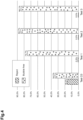
- the means 15 for orientating the polymerizable mixture comprises a wall wiper distributor 15 as the one illustrated on figure 3 .
- the wall wiper distributor 15 comprises an inlet 16 designed to be connected to the inlet 12 on the tank 10, and an outlet 17 located so as to face the wall of the tank 10.
- the inlet 16 and the outlet 17 of the wall wiper distributor 15 are connected to one another through a pipe (here a cylinder pipe) that is curved in order to place the outlet 17 close to and facing the wall 19 of the tank 10.
- the outlet 17 is delineated by a cylindrical wall (or cylinder) which free end is cut obliquely relatively to the axis of extension of the cylinder so as to form a sort of beak pointing towards the wall 19 of tank 10.
- the angle formed between the normal to the section of the free end of the cylinder and the axis of extension of said cylinder is about 30°.
- the supply device comprises a filing line connected to an inlet of the tank.
- the inlet of the tank at which is connected the filling line can either be the same inlet 12 as the one at which the looping line 20 is connected or be a distinct inlet.
- the filling line is distinct and separate from the looping line 20.
- Such filling line allows filling the tank 10 with fresh (or new) polymerizable mixture or with at least one of the reactants of said polymerizable mixture.
- the tank 10 can at the same time be emptied by flowing the polymerizable mixture in the looping line 20 and into the molding devices 200, and filled in by the introduction of new (or fresh) polymerizable mixture from the filling line.
- the introduction of fresh (new) polymerizable mixture in the tank 10 is for instance based on the measure of the level L of polymerizable mixture in the tank 10, made by the level sensor 60 previously described.
- Such filling line allows continuous operation of the molding line, as the filling of the molds does not need to be stopped for refilling the tank 10, said tank 10 being designed to be able to continuously receive fresh polymerizable mixture from the filling line.
- the supply device 100 of the invention comprises a control unit (not represented).
- the elements of the supply device 100 such as the valves 201, the pump 50, the vacuum regulator 30 and the back pressure regulator 40 are therefore designed to be controlled by said control unit.
- Such control unit is for instance designed to receive information from the vacuum regulator 30 and/or from the level sensor 60 and/or from the back pressure regulator 40 (when the supply device 100 is equipped with such).
- the invention also relates to a method for supplying the polymerizable mixture to the at least one molding device 200.
- the method of the invention comprises the following steps:
- the method of the invention is for instance implemented with the supply device 100 of the invention.
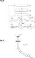
- Such method is more precisely illustrated on figure 2 and is for instance implemented by the control unit of the supply device 100, using the supply device 100.
- Step a) of the method is illustrated by the box referenced E1 on figure 2 .
- the tank 10 is for instance filled with the polymerizable mixture that has been formed in a step prior to step a).
- the various reactants of the polymerizable mixture within the tank 10 in order to form the polymerizable mixture directly inside the tank 10.
- the tank 10 receives the polymerizable mixture, or at least one of the reactants of said polymerizable mixture, from a filing line connected to the tank 10.
- the polymerizable mixture contained in the tank 10 is subjected to a pressure smaller than ambient pressure Pam, preferably lower that the set value of pressure Ps, during a predetermined period of time, so as to form a degassed polymerizable mixture.
- the degassing of the polymerizable mixture by placing said polymerizable mixture under a low pressure can for instance occur inside the tank 10, using the vacuum pump 31.
- the low pressure applied to the tank 10 for degassing the polymerizable mixture can for instance be comprised between 0.1 and 0.3 bars.
- the degassing of the polymerizable mixture could occur at a pressure equal to the set value of pressure Ps, but the step of degassing would therefore last longer than when the degassing occurs at a pressure lower than said set value of pressure Ps.
- This degassing step occurs during a finite time, and stops once steps b) and c) are implemented.
- the polymerizable mixture contained in the tank 10 at step a) is already a degassed polymerizable mixture, degassed in a step prior to step a).
- step b) is implemented prior to step c).
- the control unit of the supply device 100 controls the vacuum regulator 30 that itself controls the vacuum pump 31 in order to adjust the pressure P inside the tank 10 and reach the set value of pressure Ps.
- the set value of pressure Ps is the same as the one defined previously.
- the pressure P inside the tank 10 is lower than the set value of pressure Ps, it is possible to increase said pressure by letting gas flow inside the tank 10.
- the inert gas supplier 32 it is possible to use the inert gas supplier 32 to increase the pressure inside the tank 10 to reach the set value of pressure Ps.
- the polymerizable mixture is supplied to the molding device 200 while the pressure in the tank 10 is maintained at the set value of pressure Ps.
- Such supply here occurs through the looping line 20 which both ends are connected to the tank 10 and which is plugged to an inlet of said molding device, in between said ends, by means of a valve 201.
- step c) comprises a first sub-step during which the filling of the looping line 20 occurs while the pressure in the tank 10 is maintained at the set value of pressure Ps (box referenced E3 on figure 2 ), and a second sub-step during which the molding devices are supplied in degassed polymerizable mixture (boxes referenced E4, E41, E42, E5 and E51 on figure 2 ).
- step c) (box referenced E3) occurs while the valves 201 connecting said looping line 20 to the molding devices 200 are closed so that the inlet of each molding device 200 is disconnected from the looping line 20.
- the pressure P inside the tank 10 is controlled to be at the set value of pressure Ps, so that it is lower than ambient pressure Pam, but still sufficient for the polymerizable mixture to fill the portion of the looping line 20 that connects the outlet 11 of the tank 10 to the pump 50.
- the pump 50 is switched on to fill the whole looping line 20 and to return the polymerizable mixture to the tank 10 via the inlet 12 of the tank 10 and through the means 15 for orientating said polymerizable mixture against the wall 19.
- step c) once the looping line 20 is filled with degassed polymerizable mixture, the pressure in said the looping line 20, at the inlet of the molding device 200, is set at a value higher than the set value of pressure Ps that is maintained in the tank 10, and then maintained at said high value of pressure.
- Such difference of pressure between the tank 10 and the inlet of the molding device 200 is possible thanks to the pump 50 and the back pressure regulator 40 which can increase the pressure in the looping line 20.
- the molding devices 200 are supplied with degassed polymerizable mixture at step c).
- Such supply of the molding devices 200 with the degassed polymerizable mixture is represented by the set of boxes referenced E4, E41, E42, E5 and E51 on figure 2 .
- the vacuum regulator 30 regularly measures, preferably at very high frequency, the pressure P inside the tank 10 and the control unit then compares said pressure P with the set value of pressure Ps (box referenced E4).
- control unit controls the vacuum regulator 30 for it to control the vacuum pump 31 in order to lower said pressure P inside the tank 10.
- the control unit controls the vacuum regulator 30 for allowing gas inside the tank 10.
- the vacuum regulator 30 here controls the inert gas supplier 32 in order to increase the pressure P inside the tank 10.
- the control unit checks the level L of polymerizable mixture enclosed within the tank 10, said level L being for instance given by the level sensor 60 (box referenced E5).
- the control unit controls the supply of degassed polymerizable mixture to the molding devices 200 (box referenced E51 on figure 2 ). To do so, the control unit for instance controls the flow rate of the pump 50, the opening of at least one of the valves 201, the injection means of the corresponding molding devices 200 and the back pressure regulator 40 in order to fill in the molds while keeping the pressure at the inlet of the molding devices at a high value.
- the control unit therefore guarantees that the supply is balanced in terms of pressure and quantity of polymerizable mixture flowing in the looping line 20 and returning back to the tank 10.
- a flow of degassed polymerizable mixture in excess continuously returns to the tank 10 via the looping line 20. More precisely, the polymerizable mixture returns to the tank 10 at a flow rate that changes based on the pressure in the looping line 20, downstream of the inlet of the molding device 200. This flow rate for instance depends on the number of molding devices 200 being supplied in polymerizable mixture at the same time, that is to say on the number of valves 201 that are simultaneously open.
- step c) in order to compensate for the pressure P inside the tank 10 that is lower than the set pressure value Ps, due to filling of the molding devices 200, it is possible to control an entry of gas, preferably an entry of inert gas, into the tank 10.
- the control of the entry of inert gas is based on the pressure P contained within the tank 10.
- the entry of inert gas is here made through the vacuum regulator 30 and the inert gas supplier 32.
- the control unit stops the supply of the polymerizable mixture (box referenced E52 on figure 2 ). It implies that the control units controls the closing of the valves 201, the stopping of the pump 50 and the closing of the potential valve located at the outlet 11 of the tank 10. The tank 10 is then refilled with fresh polymerizable mixture and the method starts again from step a) (box referenced E1).
- On figure 4 is illustrated a graph showing the percentage of lenses that are rejected (“reject") after being molded and the percentage of lenses that are bubble free (“bubble free”) after being molded, that is to say that do not include any bubbles.
- Such percentages are given for lenses obtained in a comparative test (Test C0 on figure 4 ) implemented with a traditional device and/or method in which the pressure is not continuously controlled during the supply of the molds, and are also obtained in 3 other tests (Test 1, Test 2 and Test 3 on figure 4 ) implemented with the device and/or the method of the invention in which the pressure is continuously maintained at the set value of pressure Ps during the supply of the molds.
- the supply device 100 and the method of the invention allow obtaining more lenses that are bubble free, and less rejected lenses.
- the supply device 100 and/or the method of the invention allow reducing the gas redissolved in the polymerizable mixture, even after the polymerizable has been initially degassed, and therefore increasing the lenses that are bubble free after they are molded.
- the traditional supply device and/ or method results in gas being dissolved in the polymerizable mixture after it has been initially degassed, and therefore in more lenses that include bubbles and that are rejected because they cannot be used or sold.
- the vacuum regulator of the supply device comprises a pressure sensor and a controller that are physically separated.
- the pressure sensor of such vacuum regulator is connected to the tank and located on the top of the tank in order to measure the pressure of the atmosphere inside the tank.
- the controller is located at distance from the tank and does not need to be connected to the tank.
- the controller can for instance be part of the control unit of the supply device.
- the pressure sensor is able to communicate with the controller, which itself is able to communicate with the vacuum pump and the inert gas supplier in order to control them.
- the vacuum pump and the inert gas supplier are directly connected to the tank, by an inlet, either a common inlet or a distinct inlet.
Landscapes
- Engineering & Computer Science (AREA)
- Mechanical Engineering (AREA)
- Health & Medical Sciences (AREA)
- Manufacturing & Machinery (AREA)
- Ophthalmology & Optometry (AREA)
- Robotics (AREA)
- Processing And Handling Of Plastics And Other Materials For Molding In General (AREA)
- Casting Or Compression Moulding Of Plastics Or The Like (AREA)
Claims (12)
- Verfahren zum Zuführen eines polymerisierbaren Gemischs zu mindestens einer Formvorrichtung (200), das Verfahren umfassend die Schritte:a) Bereitstellen eines Behälters (10), der das polymerisierbare Gemisch enthält,b) Erreichen eines Drucksollwerts (Ps) in dem Behälter (10), der niedriger ist als der Umgebungsdruck (Pam),c) kontinuierliches Aufrechterhalten des Drucks (P) in dem Behälter (10) auf dem Drucksollwert (Ps), während das polymerisierbare Gemisch der Formvorrichtung (200) durch eine Schleifenleitung (20) zugeführt wird, deren beide Enden mit dem Behälter (10) verbunden sind und die zwischen diesen Enden mit einem Einlass der Formvorrichtung verbunden ist,wobei in Schritt c) ein Einlass von Inertgas in den Behälter (10) basierend auf dem in dem Behälter (10) herrschenden Druck (P) geregelt wird.
- Verfahren nach Anspruch 1, wobei das in dem Behälter (10) enthaltene polymerisierbare Gemisch vor Schritt b) während einer vorgegebenen Zeitdauer einem Druck ausgesetzt wird, der niedriger ist als der Drucksollwert (Ps), um ein entgastes polymerisierbares Gemisch auszubilden.
- Verfahren nach einem der Ansprüche 1 und 2, wobei in Schritt c) der Druck in der Schleifenleitung (20) am Einlass der Formvorrichtung (200) auf einem Wert gehalten wird, der höher ist als der Drucksollwert (Ps), der in dem Behälter (10) aufrechterhalten wird.
- Verfahren nach einem der Ansprüche 1 bis 3, wobei in Schritt c) ein Strom des polymerisierbaren Gemischs kontinuierlich über die Schleifenleitung (20) mit einer Strömungsrate, die sich basierend auf dem Druck in der Schleifenleitung (20) stromabwärts des Einlasses der Formvorrichtung (200) ändert, zu dem Behälter (10) zurückkehrt.
- Verfahren nach einem der Ansprüche 1 bis 4, wobei in den Schritten b) und c) der Drucksollwert (Ps) in dem Behälter (10) mindestens 0,3 Bar unter dem Umgebungsdruck (Pa) liegt.
- Verfahren nach einem der Ansprüche 1 bis 5, wobei in Schritt a) der Behälter (10) das polymerisierbare Gemisch oder mindestens einen der Reaktanten des polymerisierbaren Gemischs aus einer mit dem Behälter (10) verbundenen Füllleitung erhält.
- Versorgungsvorrichtung (100) zum Versorgen mindestens einer Formvorrichtung (200) mit einem polymerisierbaren Gemisch, umfassend:- einen Behälter (10), in dem das polymerisierbare Gemisch gelagert wird,- eine Schleifenleitung (20) zum Versorgen der mindestens einen Formvorrichtung (200) mit dem polymerisierbaren Gemisch, wobei die Schleifenleitung (20) an einem ersten Ende mit einem Auslass (11) des Behälters (10) zum Aufnehmen des polymerisierbaren Gemischs und an einem zweiten Ende mit einem Einlass (12) des Behälters (10) zum Rückführen eines Überschusses an polymerisierbarem Gemisch in den Behälter (10) und zwischen dem ersten und dem zweiten Ende mit einem Einlass der mindestens einen Formvorrichtung (200) verbunden ist,- einen Unterdruckregler (30) zum Erreichen eines Drucksollwerts (Ps) in dem Behälter (10), der niedriger ist als der Umgebungsdruck (Pam), und zum kontinuierlichen Aufrechterhalten des Drucks (P) in dem Behälter auf dem Drucksollwert (Ps), wobei der Vakuumregler (30) dazu ausgebildet ist, einerseits eine mit dem Behälter (10) verbundene Unterdruckpumpe (31) zum Absenken des Drucks (P) in dem Behälter (10) und andererseits eine mit dem Behälter (10) verbundene Inertgasquelle (32) zum Erhöhen des Drucks (P) in dem Behälter (10) zu steuern.
- Versorgungsvorrichtung (100) nach Anspruch 7, wobei die Schleifenleitung (20) eine Pumpe (50) mit einstellbarer Geschwindigkeit umfasst, um den Einlass der mindestens einen Formvorrichtung (200) mit dem polymerisierbaren Gemisch aus dem Behälter (10) mit einer festgelegten Strömungsrate zu versorgen.
- Versorgungsvorrichtung nach einem der Ansprüche 7 und 8, wobei die Schleifenleitung (20) einen Gegendruckregler (40) umfasst, der stromabwärts des Einlasses der Formvorrichtung (200) und stromaufwärts des Einlasses (12) des Behälters (10) angeordnet ist, um den Druck in der Schleifenleitung (20) am Einlass der mindestens einen Formvorrichtung (200) auf einem höheren Wert als dem Drucksollwert (Ps) zu halten.
- Versorgungsvorrichtung (100) nach einem der Ansprüche 7 bis 9, wobei der Einlass (12) des Behälters (10) mit Mitteln (15) zum Richten des Überschusses an polymerisierbarem Gemisch gegen die Wand (19) des Behälters (10) versehen ist.
- Versorgungsvorrichtung (100) nach einem der Ansprüche 7 bis 10, die einen Füllstandssensor (60) zum Überprüfen des Füllstands (L) des polymerisierbaren Gemischs in dem Behälter (10) umfasst.
- Versorgungsvorrichtung (100) nach einem der Ansprüche 7 bis 11, wobei die Formvorrichtung (200) eine Vorrichtung zum Formen von ophthalmischen Linsen ist.
Applications Claiming Priority (2)
| Application Number | Priority Date | Filing Date | Title |
|---|---|---|---|
| EP21305231 | 2021-02-26 | ||
| PCT/EP2022/054867 WO2022180240A1 (en) | 2021-02-26 | 2022-02-25 | Method for supplying a molding device with polymerizable mixture and associated supply device |
Publications (2)
| Publication Number | Publication Date |
|---|---|
| EP4297946A1 EP4297946A1 (de) | 2024-01-03 |
| EP4297946B1 true EP4297946B1 (de) | 2024-10-30 |
Family
ID=75173204
Family Applications (1)
| Application Number | Title | Priority Date | Filing Date |
|---|---|---|---|
| EP22708139.5A Active EP4297946B1 (de) | 2021-02-26 | 2022-02-25 | Verfahren zur versorgung einer giessvorrichtung mit polymerisierbarem gemisch und zugehörige versorgungsvorrichtung |
Country Status (5)
| Country | Link |
|---|---|
| US (1) | US12558859B2 (de) |
| EP (1) | EP4297946B1 (de) |
| CN (1) | CN116710256B (de) |
| MX (1) | MX2023010018A (de) |
| WO (1) | WO2022180240A1 (de) |
Family Cites Families (25)
| Publication number | Priority date | Publication date | Assignee | Title |
|---|---|---|---|---|
| US3212128A (en) * | 1963-03-20 | 1965-10-19 | Air Prod & Chem | Mold filling apparatus |
| DE2748982C2 (de) * | 1977-11-02 | 1987-10-01 | Wilhelm Hedrich Vakuumanlagen GmbH und Co KG, 6332 Ehringshausen | Anordnung zum Füllen von Gießformen mit Gießharz od.dgl. gießfähig flüssigen Medien |
| DE3307396A1 (de) | 1983-03-02 | 1984-09-06 | Volta-Werke Elektricitäts-Gesellschaft mbH, 1000 Berlin | Verfahren zum umgiessen von metallkoerpern, insbesondere wicklungen von transformatoren |
| JPH01200907A (ja) | 1987-11-13 | 1989-08-14 | Nkk Corp | 粉体の鋳込み成形方法およびその装置 |
| GB8916751D0 (en) * | 1989-07-21 | 1989-09-06 | Babcock Transformers Limited | Producing moulded castings in polymer materials |
| DE69115532T2 (de) * | 1990-02-27 | 1996-05-15 | Toray Industries | Gasdurchlässiges spiralförmig gewickeltes Membranmodul, Vorrichtung und Verfahren zu seiner Verwendung |
| US5187001A (en) * | 1990-09-26 | 1993-02-16 | Gencorp Inc. | Resin transfer molding apparatus |
| DE4210687C2 (de) * | 1992-04-01 | 2002-01-17 | Huebers Verfahrenstech | Vorrichtung für die Abgabe zähflüssiger, aushärtender Stoffe, sowie Verfahren zum Betrieb einer derartigen Vorrichtung |
| EP0598424A3 (de) | 1992-11-16 | 1996-05-15 | Novellus Systems Inc | Vorrichtung zur Entfernung von gelösten Gasen aus einer Flüssigkeit. |
| US5435943A (en) * | 1994-03-11 | 1995-07-25 | Johnson & Johnson Vision Products, Inc. | Method and apparatus for making an ophthalmic lens |
| US5658602A (en) * | 1994-06-10 | 1997-08-19 | Johnson & Johnson Vision Products, Inc. | Method and apparatus for contact lens mold filling and assembly |
| US5922249A (en) | 1995-12-08 | 1999-07-13 | Novartis Ag | Ophthalmic lens production process |
| US6811592B2 (en) | 2002-03-01 | 2004-11-02 | Johnson & Johnson Vision Care, Inc. | Thin film in-line degasser |
| JP2004209968A (ja) | 2002-12-18 | 2004-07-29 | Seiko Epson Corp | プラスチックレンズの製造方法及び原料貯蔵供給装置 |
| DE10309814B3 (de) * | 2003-03-05 | 2004-09-16 | Krauss-Maffei Kunststofftechnik Gmbh | Verfahren zur Herstellung von Bauteilen mit einer kompakten Polyurethan (PUR)-Versiegelungsschicht |
| FR2856007B1 (fr) * | 2003-06-11 | 2005-08-26 | Essilor Int | Vanne et dispositif d'alimentation convenant au remplissage, avec une matiere polymerisable, d'une cavite de moulage |
| CN101648421B (zh) * | 2004-06-08 | 2014-10-15 | Hoya株式会社 | 塑料透镜的制造方法、成形用密封垫片及成形模、原料液注入夹具、成形模保持夹具 |
| US7275928B2 (en) * | 2004-11-23 | 2007-10-02 | Rohm And Haas Electronic Materials Cmp Holdings, Inc. | Apparatus for forming a striation reduced chemical mechanical polishing pad |
| US20090121370A1 (en) | 2007-10-26 | 2009-05-14 | Bausch & Lomb Incorporated | Molds for Production of Ophthalmic Devices |
| WO2009076049A1 (en) * | 2007-12-10 | 2009-06-18 | Bausch & Lomb Incorporated | Apparatus and method for degassing a fluid to enhance inspection of ophthalmic devices |
| DE102012103668A1 (de) | 2012-04-26 | 2013-10-31 | Hedrich Gmbh | Vorratsbehälter für Gießharz sowie Verfahren und Vorrichtung zum Vergießen von Gießharz |
| EP2889113A1 (de) | 2013-12-27 | 2015-07-01 | ESSILOR INTERNATIONAL (Compagnie Générale d'Optique) | Maschine und Verfahren zum automatischen Füllen einer Form zum Formen einer ophthalmischen Linse |
| FR3028202B1 (fr) * | 2014-11-06 | 2017-10-06 | Essilor Int | Dispositif d'alimentation d'un dispositif de moulage, ligne de moulage et procede de pilotage de la ligne de moulage |
| US20210071861A1 (en) * | 2019-09-11 | 2021-03-11 | Air Products And Chemicals, Inc. | Steam-Producing Process and System |
| KR20230162776A (ko) * | 2021-03-31 | 2023-11-28 | 에씰로 앙터나시오날 | 몰드에 중합성 혼합물을 공급하기 위한 장치 및 방법 |
-
2022
- 2022-02-25 EP EP22708139.5A patent/EP4297946B1/de active Active
- 2022-02-25 WO PCT/EP2022/054867 patent/WO2022180240A1/en not_active Ceased
- 2022-02-25 CN CN202280009118.3A patent/CN116710256B/zh active Active
- 2022-02-25 US US18/278,525 patent/US12558859B2/en active Active
- 2022-02-25 MX MX2023010018A patent/MX2023010018A/es unknown
Also Published As
| Publication number | Publication date |
|---|---|
| MX2023010018A (es) | 2023-09-07 |
| US12558859B2 (en) | 2026-02-24 |
| CN116710256A (zh) | 2023-09-05 |
| EP4297946A1 (de) | 2024-01-03 |
| WO2022180240A1 (en) | 2022-09-01 |
| US20240051191A1 (en) | 2024-02-15 |
| CN116710256B (zh) | 2025-12-23 |
Similar Documents
| Publication | Publication Date | Title |
|---|---|---|
| CN101356401B (zh) | 用于充装加压气体容器的方法和设备 | |
| CN101626823B (zh) | 将液体与至少另一种物质混合和将混合物脱气以及将混合物排放的方法 | |
| US12515375B2 (en) | Device for supplying a mold with a polymerizable mixture | |
| US7311005B2 (en) | Method and device for continuous measuring of dynamic fluid consumption, including pressure regulator | |
| US6695017B1 (en) | Method and apparatus for filling a pressure tank with a fluid | |
| KR102538206B1 (ko) | 충전장치 | |
| EP4297946B1 (de) | Verfahren zur versorgung einer giessvorrichtung mit polymerisierbarem gemisch und zugehörige versorgungsvorrichtung | |
| CN107073850B (zh) | 用于成型装置的供应装置、成型生产线、以及用于控制所述成型生产线的方法 | |
| US5551486A (en) | Method and equipment for filing casting molds with casting resin or similarly casting-ready liquid media | |
| KR101099256B1 (ko) | 도포장치 및 도포방법 | |
| CN111212808A (zh) | 用于用填充产品填充容器的装置 | |
| CN113357532B (zh) | 填充装置 | |
| JP2006281614A (ja) | プラスチック原料注入方法及びプラスチック原料注入装置並びにプラスチックレンズ | |
| CN210739983U (zh) | 一种稀释剂加注系统 | |
| US10723092B2 (en) | Method and apparatus for manufacturing an optical article | |
| JP4671735B2 (ja) | プラスチック原料注入装置 | |
| US20240109231A1 (en) | Multi-directional casting nozzle | |
| JP4761807B2 (ja) | プラスチック原料注入装置及びプラスチック原料注入方法 | |
| CN215849143U (zh) | 一种熔体输送设备 | |
| KR101054720B1 (ko) | 액상 수지 주입장치 | |
| JP2006281617A (ja) | プラスチック原料注入方法、プラスチック原料注入装置及びプラスチック原料注入ノズル並びにプラスチックレンズ | |
| CN120558489A (zh) | 气密性试验系统、试验方法和气密试验介质回收方法 | |
| SU952432A1 (ru) | Устройство дл дозировани жидкого металла в машину лить под давлением | |
| HK1135349B (en) | Method for mixing a liquid with at least one additional substance, degassing said mixture and dispensing said mixture | |
| HK1135349A (en) | Method for mixing a liquid with at least one additional substance, degassing said mixture and dispensing said mixture |
Legal Events
| Date | Code | Title | Description |
|---|---|---|---|
| STAA | Information on the status of an ep patent application or granted ep patent |
Free format text: STATUS: UNKNOWN |
|
| STAA | Information on the status of an ep patent application or granted ep patent |
Free format text: STATUS: THE INTERNATIONAL PUBLICATION HAS BEEN MADE |
|
| PUAI | Public reference made under article 153(3) epc to a published international application that has entered the european phase |
Free format text: ORIGINAL CODE: 0009012 |
|
| STAA | Information on the status of an ep patent application or granted ep patent |
Free format text: STATUS: REQUEST FOR EXAMINATION WAS MADE |
|
| 17P | Request for examination filed |
Effective date: 20230830 |
|
| AK | Designated contracting states |
Kind code of ref document: A1 Designated state(s): AL AT BE BG CH CY CZ DE DK EE ES FI FR GB GR HR HU IE IS IT LI LT LU LV MC MK MT NL NO PL PT RO RS SE SI SK SM TR |
|
| DAV | Request for validation of the european patent (deleted) | ||
| DAX | Request for extension of the european patent (deleted) | ||
| GRAP | Despatch of communication of intention to grant a patent |
Free format text: ORIGINAL CODE: EPIDOSNIGR1 |
|
| STAA | Information on the status of an ep patent application or granted ep patent |
Free format text: STATUS: GRANT OF PATENT IS INTENDED |
|
| INTG | Intention to grant announced |
Effective date: 20240705 |
|
| GRAS | Grant fee paid |
Free format text: ORIGINAL CODE: EPIDOSNIGR3 |
|
| GRAA | (expected) grant |
Free format text: ORIGINAL CODE: 0009210 |
|
| STAA | Information on the status of an ep patent application or granted ep patent |
Free format text: STATUS: THE PATENT HAS BEEN GRANTED |
|
| AK | Designated contracting states |
Kind code of ref document: B1 Designated state(s): AL AT BE BG CH CY CZ DE DK EE ES FI FR GB GR HR HU IE IS IT LI LT LU LV MC MK MT NL NO PL PT RO RS SE SI SK SM TR |
|
| REG | Reference to a national code |
Ref country code: GB Ref legal event code: FG4D |
|
| REG | Reference to a national code |
Ref country code: CH Ref legal event code: EP |
|
| REG | Reference to a national code |
Ref country code: IE Ref legal event code: FG4D |
|
| REG | Reference to a national code |
Ref country code: DE Ref legal event code: R096 Ref document number: 602022007279 Country of ref document: DE |
|
| REG | Reference to a national code |
Ref country code: LT Ref legal event code: MG9D |
|
| REG | Reference to a national code |
Ref country code: NL Ref legal event code: MP Effective date: 20241030 |
|
| PG25 | Lapsed in a contracting state [announced via postgrant information from national office to epo] |
Ref country code: HR Free format text: LAPSE BECAUSE OF FAILURE TO SUBMIT A TRANSLATION OF THE DESCRIPTION OR TO PAY THE FEE WITHIN THE PRESCRIBED TIME-LIMIT Effective date: 20241030 Ref country code: IS Free format text: LAPSE BECAUSE OF FAILURE TO SUBMIT A TRANSLATION OF THE DESCRIPTION OR TO PAY THE FEE WITHIN THE PRESCRIBED TIME-LIMIT Effective date: 20250228 Ref country code: PT Free format text: LAPSE BECAUSE OF FAILURE TO SUBMIT A TRANSLATION OF THE DESCRIPTION OR TO PAY THE FEE WITHIN THE PRESCRIBED TIME-LIMIT Effective date: 20250228 |
|
| PG25 | Lapsed in a contracting state [announced via postgrant information from national office to epo] |
Ref country code: FI Free format text: LAPSE BECAUSE OF FAILURE TO SUBMIT A TRANSLATION OF THE DESCRIPTION OR TO PAY THE FEE WITHIN THE PRESCRIBED TIME-LIMIT Effective date: 20241030 Ref country code: NL Free format text: LAPSE BECAUSE OF FAILURE TO SUBMIT A TRANSLATION OF THE DESCRIPTION OR TO PAY THE FEE WITHIN THE PRESCRIBED TIME-LIMIT Effective date: 20241030 |
|
| REG | Reference to a national code |
Ref country code: AT Ref legal event code: MK05 Ref document number: 1736495 Country of ref document: AT Kind code of ref document: T Effective date: 20241030 |
|
| PG25 | Lapsed in a contracting state [announced via postgrant information from national office to epo] |
Ref country code: BG Free format text: LAPSE BECAUSE OF FAILURE TO SUBMIT A TRANSLATION OF THE DESCRIPTION OR TO PAY THE FEE WITHIN THE PRESCRIBED TIME-LIMIT Effective date: 20241030 |
|
| PG25 | Lapsed in a contracting state [announced via postgrant information from national office to epo] |
Ref country code: ES Free format text: LAPSE BECAUSE OF FAILURE TO SUBMIT A TRANSLATION OF THE DESCRIPTION OR TO PAY THE FEE WITHIN THE PRESCRIBED TIME-LIMIT Effective date: 20241030 |
|
| PG25 | Lapsed in a contracting state [announced via postgrant information from national office to epo] |
Ref country code: NO Free format text: LAPSE BECAUSE OF FAILURE TO SUBMIT A TRANSLATION OF THE DESCRIPTION OR TO PAY THE FEE WITHIN THE PRESCRIBED TIME-LIMIT Effective date: 20250130 |
|
| PG25 | Lapsed in a contracting state [announced via postgrant information from national office to epo] |
Ref country code: AT Free format text: LAPSE BECAUSE OF FAILURE TO SUBMIT A TRANSLATION OF THE DESCRIPTION OR TO PAY THE FEE WITHIN THE PRESCRIBED TIME-LIMIT Effective date: 20241030 Ref country code: GR Free format text: LAPSE BECAUSE OF FAILURE TO SUBMIT A TRANSLATION OF THE DESCRIPTION OR TO PAY THE FEE WITHIN THE PRESCRIBED TIME-LIMIT Effective date: 20250131 Ref country code: LV Free format text: LAPSE BECAUSE OF FAILURE TO SUBMIT A TRANSLATION OF THE DESCRIPTION OR TO PAY THE FEE WITHIN THE PRESCRIBED TIME-LIMIT Effective date: 20241030 |
|
| PG25 | Lapsed in a contracting state [announced via postgrant information from national office to epo] |
Ref country code: PL Free format text: LAPSE BECAUSE OF FAILURE TO SUBMIT A TRANSLATION OF THE DESCRIPTION OR TO PAY THE FEE WITHIN THE PRESCRIBED TIME-LIMIT Effective date: 20241030 |
|
| PG25 | Lapsed in a contracting state [announced via postgrant information from national office to epo] |
Ref country code: RS Free format text: LAPSE BECAUSE OF FAILURE TO SUBMIT A TRANSLATION OF THE DESCRIPTION OR TO PAY THE FEE WITHIN THE PRESCRIBED TIME-LIMIT Effective date: 20250130 |
|
| PG25 | Lapsed in a contracting state [announced via postgrant information from national office to epo] |
Ref country code: SM Free format text: LAPSE BECAUSE OF FAILURE TO SUBMIT A TRANSLATION OF THE DESCRIPTION OR TO PAY THE FEE WITHIN THE PRESCRIBED TIME-LIMIT Effective date: 20241030 |
|
| PG25 | Lapsed in a contracting state [announced via postgrant information from national office to epo] |
Ref country code: DK Free format text: LAPSE BECAUSE OF FAILURE TO SUBMIT A TRANSLATION OF THE DESCRIPTION OR TO PAY THE FEE WITHIN THE PRESCRIBED TIME-LIMIT Effective date: 20241030 |
|
| PG25 | Lapsed in a contracting state [announced via postgrant information from national office to epo] |
Ref country code: EE Free format text: LAPSE BECAUSE OF FAILURE TO SUBMIT A TRANSLATION OF THE DESCRIPTION OR TO PAY THE FEE WITHIN THE PRESCRIBED TIME-LIMIT Effective date: 20241030 |
|
| PG25 | Lapsed in a contracting state [announced via postgrant information from national office to epo] |
Ref country code: RO Free format text: LAPSE BECAUSE OF FAILURE TO SUBMIT A TRANSLATION OF THE DESCRIPTION OR TO PAY THE FEE WITHIN THE PRESCRIBED TIME-LIMIT Effective date: 20241030 |
|
| PG25 | Lapsed in a contracting state [announced via postgrant information from national office to epo] |
Ref country code: SK Free format text: LAPSE BECAUSE OF FAILURE TO SUBMIT A TRANSLATION OF THE DESCRIPTION OR TO PAY THE FEE WITHIN THE PRESCRIBED TIME-LIMIT Effective date: 20241030 |
|
| PG25 | Lapsed in a contracting state [announced via postgrant information from national office to epo] |
Ref country code: CZ Free format text: LAPSE BECAUSE OF FAILURE TO SUBMIT A TRANSLATION OF THE DESCRIPTION OR TO PAY THE FEE WITHIN THE PRESCRIBED TIME-LIMIT Effective date: 20241030 |
|
| REG | Reference to a national code |
Ref country code: DE Ref legal event code: R097 Ref document number: 602022007279 Country of ref document: DE |
|
| PLBE | No opposition filed within time limit |
Free format text: ORIGINAL CODE: 0009261 |
|
| STAA | Information on the status of an ep patent application or granted ep patent |
Free format text: STATUS: NO OPPOSITION FILED WITHIN TIME LIMIT |
|
| PG25 | Lapsed in a contracting state [announced via postgrant information from national office to epo] |
Ref country code: SE Free format text: LAPSE BECAUSE OF FAILURE TO SUBMIT A TRANSLATION OF THE DESCRIPTION OR TO PAY THE FEE WITHIN THE PRESCRIBED TIME-LIMIT Effective date: 20241030 |
|
| PG25 | Lapsed in a contracting state [announced via postgrant information from national office to epo] |
Ref country code: MC Free format text: LAPSE BECAUSE OF FAILURE TO SUBMIT A TRANSLATION OF THE DESCRIPTION OR TO PAY THE FEE WITHIN THE PRESCRIBED TIME-LIMIT Effective date: 20241030 |
|
| REG | Reference to a national code |
Ref country code: CH Ref legal event code: PL |
|
| 26N | No opposition filed |
Effective date: 20250731 |
|
| PG25 | Lapsed in a contracting state [announced via postgrant information from national office to epo] |
Ref country code: LU Free format text: LAPSE BECAUSE OF NON-PAYMENT OF DUE FEES Effective date: 20250225 |
|
| PG25 | Lapsed in a contracting state [announced via postgrant information from national office to epo] |
Ref country code: CH Free format text: LAPSE BECAUSE OF NON-PAYMENT OF DUE FEES Effective date: 20250228 |
|
| REG | Reference to a national code |
Ref country code: BE Ref legal event code: MM Effective date: 20250228 |
|
| PG25 | Lapsed in a contracting state [announced via postgrant information from national office to epo] |
Ref country code: BE Free format text: LAPSE BECAUSE OF NON-PAYMENT OF DUE FEES Effective date: 20250228 |
|
| PGFP | Annual fee paid to national office [announced via postgrant information from national office to epo] |
Ref country code: GB Payment date: 20260227 Year of fee payment: 5 |
|
| PGFP | Annual fee paid to national office [announced via postgrant information from national office to epo] |
Ref country code: IE Payment date: 20260227 Year of fee payment: 5 Ref country code: DE Payment date: 20260227 Year of fee payment: 5 |
|
| PGFP | Annual fee paid to national office [announced via postgrant information from national office to epo] |
Ref country code: IT Payment date: 20260219 Year of fee payment: 5 |
|
| PGFP | Annual fee paid to national office [announced via postgrant information from national office to epo] |
Ref country code: FR Payment date: 20260225 Year of fee payment: 5 |