EP4295792A2 - Draht für ein endovaskuläres gerät - Google Patents
Draht für ein endovaskuläres gerät Download PDFInfo
- Publication number
- EP4295792A2 EP4295792A2 EP23195560.0A EP23195560A EP4295792A2 EP 4295792 A2 EP4295792 A2 EP 4295792A2 EP 23195560 A EP23195560 A EP 23195560A EP 4295792 A2 EP4295792 A2 EP 4295792A2
- Authority
- EP
- European Patent Office
- Prior art keywords
- wire
- section
- length
- distal
- distal tip
- Prior art date
- Legal status (The legal status is an assumption and is not a legal conclusion. Google has not performed a legal analysis and makes no representation as to the accuracy of the status listed.)
- Granted
Links
Images


Classifications
-
- A—HUMAN NECESSITIES
- A61—MEDICAL OR VETERINARY SCIENCE; HYGIENE
- A61B—DIAGNOSIS; SURGERY; IDENTIFICATION
- A61B17/00—Surgical instruments, devices or methods
- A61B17/22—Implements for squeezing-off ulcers or the like on inner organs of the body; Implements for scraping-out cavities of body organs, e.g. bones; for invasive removal or destruction of calculus using mechanical vibrations; for removing obstructions in blood vessels, not otherwise provided for
- A61B17/22004—Implements for squeezing-off ulcers or the like on inner organs of the body; Implements for scraping-out cavities of body organs, e.g. bones; for invasive removal or destruction of calculus using mechanical vibrations; for removing obstructions in blood vessels, not otherwise provided for using mechanical vibrations, e.g. ultrasonic shock waves
- A61B17/22012—Implements for squeezing-off ulcers or the like on inner organs of the body; Implements for scraping-out cavities of body organs, e.g. bones; for invasive removal or destruction of calculus using mechanical vibrations; for removing obstructions in blood vessels, not otherwise provided for using mechanical vibrations, e.g. ultrasonic shock waves in direct contact with, or very close to, the obstruction or concrement
- A61B17/2202—Implements for squeezing-off ulcers or the like on inner organs of the body; Implements for scraping-out cavities of body organs, e.g. bones; for invasive removal or destruction of calculus using mechanical vibrations; for removing obstructions in blood vessels, not otherwise provided for using mechanical vibrations, e.g. ultrasonic shock waves in direct contact with, or very close to, the obstruction or concrement the ultrasound transducer being inside patient's body at the distal end of the catheter
-
- A—HUMAN NECESSITIES
- A61—MEDICAL OR VETERINARY SCIENCE; HYGIENE
- A61B—DIAGNOSIS; SURGERY; IDENTIFICATION
- A61B17/00—Surgical instruments, devices or methods
- A61B17/32—Surgical cutting instruments
- A61B17/3205—Excision instruments
- A61B17/3207—Atherectomy devices working by cutting or abrading; Similar devices specially adapted for non-vascular obstructions
- A61B17/320708—Curettes, e.g. hollow scraping instruments
-
- A—HUMAN NECESSITIES
- A61—MEDICAL OR VETERINARY SCIENCE; HYGIENE
- A61B—DIAGNOSIS; SURGERY; IDENTIFICATION
- A61B90/00—Instruments, implements or accessories specially adapted for surgery or diagnosis and not covered by any of the groups A61B1/00 - A61B50/00, e.g. for luxation treatment or for protecting wound edges
- A61B90/39—Markers, e.g. radio-opaque or breast lesions markers
-
- A—HUMAN NECESSITIES
- A61—MEDICAL OR VETERINARY SCIENCE; HYGIENE
- A61B—DIAGNOSIS; SURGERY; IDENTIFICATION
- A61B17/00—Surgical instruments, devices or methods
- A61B2017/0046—Surgical instruments, devices or methods with a releasable handle; with handle and operating part separable
- A61B2017/00469—Surgical instruments, devices or methods with a releasable handle; with handle and operating part separable for insertion of instruments, e.g. guide wire, optical fibre
-
- A—HUMAN NECESSITIES
- A61—MEDICAL OR VETERINARY SCIENCE; HYGIENE
- A61B—DIAGNOSIS; SURGERY; IDENTIFICATION
- A61B17/00—Surgical instruments, devices or methods
- A61B2017/00477—Coupling
-
- A—HUMAN NECESSITIES
- A61—MEDICAL OR VETERINARY SCIENCE; HYGIENE
- A61B—DIAGNOSIS; SURGERY; IDENTIFICATION
- A61B17/00—Surgical instruments, devices or methods
- A61B17/22—Implements for squeezing-off ulcers or the like on inner organs of the body; Implements for scraping-out cavities of body organs, e.g. bones; for invasive removal or destruction of calculus using mechanical vibrations; for removing obstructions in blood vessels, not otherwise provided for
- A61B17/22004—Implements for squeezing-off ulcers or the like on inner organs of the body; Implements for scraping-out cavities of body organs, e.g. bones; for invasive removal or destruction of calculus using mechanical vibrations; for removing obstructions in blood vessels, not otherwise provided for using mechanical vibrations, e.g. ultrasonic shock waves
- A61B17/22012—Implements for squeezing-off ulcers or the like on inner organs of the body; Implements for scraping-out cavities of body organs, e.g. bones; for invasive removal or destruction of calculus using mechanical vibrations; for removing obstructions in blood vessels, not otherwise provided for using mechanical vibrations, e.g. ultrasonic shock waves in direct contact with, or very close to, the obstruction or concrement
- A61B2017/22014—Implements for squeezing-off ulcers or the like on inner organs of the body; Implements for scraping-out cavities of body organs, e.g. bones; for invasive removal or destruction of calculus using mechanical vibrations; for removing obstructions in blood vessels, not otherwise provided for using mechanical vibrations, e.g. ultrasonic shock waves in direct contact with, or very close to, the obstruction or concrement the ultrasound transducer being outside patient's body; with an ultrasound transmission member; with a wave guide; with a vibrated guide wire
- A61B2017/22015—Implements for squeezing-off ulcers or the like on inner organs of the body; Implements for scraping-out cavities of body organs, e.g. bones; for invasive removal or destruction of calculus using mechanical vibrations; for removing obstructions in blood vessels, not otherwise provided for using mechanical vibrations, e.g. ultrasonic shock waves in direct contact with, or very close to, the obstruction or concrement the ultrasound transducer being outside patient's body; with an ultrasound transmission member; with a wave guide; with a vibrated guide wire with details of the transmission member
- A61B2017/22017—Implements for squeezing-off ulcers or the like on inner organs of the body; Implements for scraping-out cavities of body organs, e.g. bones; for invasive removal or destruction of calculus using mechanical vibrations; for removing obstructions in blood vessels, not otherwise provided for using mechanical vibrations, e.g. ultrasonic shock waves in direct contact with, or very close to, the obstruction or concrement the ultrasound transducer being outside patient's body; with an ultrasound transmission member; with a wave guide; with a vibrated guide wire with details of the transmission member the ultrasonic transmitting members being fibres
-
- A—HUMAN NECESSITIES
- A61—MEDICAL OR VETERINARY SCIENCE; HYGIENE
- A61B—DIAGNOSIS; SURGERY; IDENTIFICATION
- A61B17/00—Surgical instruments, devices or methods
- A61B17/22—Implements for squeezing-off ulcers or the like on inner organs of the body; Implements for scraping-out cavities of body organs, e.g. bones; for invasive removal or destruction of calculus using mechanical vibrations; for removing obstructions in blood vessels, not otherwise provided for
- A61B17/22004—Implements for squeezing-off ulcers or the like on inner organs of the body; Implements for scraping-out cavities of body organs, e.g. bones; for invasive removal or destruction of calculus using mechanical vibrations; for removing obstructions in blood vessels, not otherwise provided for using mechanical vibrations, e.g. ultrasonic shock waves
- A61B2017/22027—Features of transducers
-
- A—HUMAN NECESSITIES
- A61—MEDICAL OR VETERINARY SCIENCE; HYGIENE
- A61B—DIAGNOSIS; SURGERY; IDENTIFICATION
- A61B17/00—Surgical instruments, devices or methods
- A61B17/22—Implements for squeezing-off ulcers or the like on inner organs of the body; Implements for scraping-out cavities of body organs, e.g. bones; for invasive removal or destruction of calculus using mechanical vibrations; for removing obstructions in blood vessels, not otherwise provided for
- A61B2017/22038—Implements for squeezing-off ulcers or the like on inner organs of the body; Implements for scraping-out cavities of body organs, e.g. bones; for invasive removal or destruction of calculus using mechanical vibrations; for removing obstructions in blood vessels, not otherwise provided for with a guide wire
- A61B2017/22039—Implements for squeezing-off ulcers or the like on inner organs of the body; Implements for scraping-out cavities of body organs, e.g. bones; for invasive removal or destruction of calculus using mechanical vibrations; for removing obstructions in blood vessels, not otherwise provided for with a guide wire eccentric
-
- A—HUMAN NECESSITIES
- A61—MEDICAL OR VETERINARY SCIENCE; HYGIENE
- A61B—DIAGNOSIS; SURGERY; IDENTIFICATION
- A61B17/00—Surgical instruments, devices or methods
- A61B17/22—Implements for squeezing-off ulcers or the like on inner organs of the body; Implements for scraping-out cavities of body organs, e.g. bones; for invasive removal or destruction of calculus using mechanical vibrations; for removing obstructions in blood vessels, not otherwise provided for
- A61B2017/22038—Implements for squeezing-off ulcers or the like on inner organs of the body; Implements for scraping-out cavities of body organs, e.g. bones; for invasive removal or destruction of calculus using mechanical vibrations; for removing obstructions in blood vessels, not otherwise provided for with a guide wire
- A61B2017/22041—Implements for squeezing-off ulcers or the like on inner organs of the body; Implements for scraping-out cavities of body organs, e.g. bones; for invasive removal or destruction of calculus using mechanical vibrations; for removing obstructions in blood vessels, not otherwise provided for with a guide wire outside the catheter
-
- A—HUMAN NECESSITIES
- A61—MEDICAL OR VETERINARY SCIENCE; HYGIENE
- A61B—DIAGNOSIS; SURGERY; IDENTIFICATION
- A61B17/00—Surgical instruments, devices or methods
- A61B17/22—Implements for squeezing-off ulcers or the like on inner organs of the body; Implements for scraping-out cavities of body organs, e.g. bones; for invasive removal or destruction of calculus using mechanical vibrations; for removing obstructions in blood vessels, not otherwise provided for
- A61B2017/22038—Implements for squeezing-off ulcers or the like on inner organs of the body; Implements for scraping-out cavities of body organs, e.g. bones; for invasive removal or destruction of calculus using mechanical vibrations; for removing obstructions in blood vessels, not otherwise provided for with a guide wire
- A61B2017/22042—Details of the tip of the guide wire
- A61B2017/22044—Details of the tip of the guide wire with a pointed tip
-
- A—HUMAN NECESSITIES
- A61—MEDICAL OR VETERINARY SCIENCE; HYGIENE
- A61B—DIAGNOSIS; SURGERY; IDENTIFICATION
- A61B17/00—Surgical instruments, devices or methods
- A61B17/22—Implements for squeezing-off ulcers or the like on inner organs of the body; Implements for scraping-out cavities of body organs, e.g. bones; for invasive removal or destruction of calculus using mechanical vibrations; for removing obstructions in blood vessels, not otherwise provided for
- A61B2017/22038—Implements for squeezing-off ulcers or the like on inner organs of the body; Implements for scraping-out cavities of body organs, e.g. bones; for invasive removal or destruction of calculus using mechanical vibrations; for removing obstructions in blood vessels, not otherwise provided for with a guide wire
- A61B2017/22049—Means for locking the guide wire in the catheter
-
- A—HUMAN NECESSITIES
- A61—MEDICAL OR VETERINARY SCIENCE; HYGIENE
- A61B—DIAGNOSIS; SURGERY; IDENTIFICATION
- A61B17/00—Surgical instruments, devices or methods
- A61B17/22—Implements for squeezing-off ulcers or the like on inner organs of the body; Implements for scraping-out cavities of body organs, e.g. bones; for invasive removal or destruction of calculus using mechanical vibrations; for removing obstructions in blood vessels, not otherwise provided for
- A61B2017/22094—Implements for squeezing-off ulcers or the like on inner organs of the body; Implements for scraping-out cavities of body organs, e.g. bones; for invasive removal or destruction of calculus using mechanical vibrations; for removing obstructions in blood vessels, not otherwise provided for for crossing total occlusions, i.e. piercing
-
- A—HUMAN NECESSITIES
- A61—MEDICAL OR VETERINARY SCIENCE; HYGIENE
- A61B—DIAGNOSIS; SURGERY; IDENTIFICATION
- A61B17/00—Surgical instruments, devices or methods
- A61B17/32—Surgical cutting instruments
- A61B17/320068—Surgical cutting instruments using mechanical vibrations, e.g. ultrasonic
- A61B2017/320088—Surgical cutting instruments using mechanical vibrations, e.g. ultrasonic with acoustic insulation, e.g. elements for damping vibrations between horn and surrounding sheath
-
- A—HUMAN NECESSITIES
- A61—MEDICAL OR VETERINARY SCIENCE; HYGIENE
- A61B—DIAGNOSIS; SURGERY; IDENTIFICATION
- A61B90/00—Instruments, implements or accessories specially adapted for surgery or diagnosis and not covered by any of the groups A61B1/00 - A61B50/00, e.g. for luxation treatment or for protecting wound edges
- A61B90/08—Accessories or related features not otherwise provided for
- A61B2090/0807—Indication means
- A61B2090/0808—Indication means for indicating correct assembly of components, e.g. of the surgical apparatus
-
- A—HUMAN NECESSITIES
- A61—MEDICAL OR VETERINARY SCIENCE; HYGIENE
- A61B—DIAGNOSIS; SURGERY; IDENTIFICATION
- A61B90/00—Instruments, implements or accessories specially adapted for surgery or diagnosis and not covered by any of the groups A61B1/00 - A61B50/00, e.g. for luxation treatment or for protecting wound edges
- A61B90/39—Markers, e.g. radio-opaque or breast lesions markers
- A61B2090/3966—Radiopaque markers visible in an X-ray image
-
- A—HUMAN NECESSITIES
- A61—MEDICAL OR VETERINARY SCIENCE; HYGIENE
- A61B—DIAGNOSIS; SURGERY; IDENTIFICATION
- A61B2217/00—General characteristics of surgical instruments
- A61B2217/002—Auxiliary appliance
- A61B2217/007—Auxiliary appliance with irrigation system
Definitions
- the present invention relates to treatment of ischaemia by using an ultrasonically activated wire or other elongate element to cross through a blockage in a blood vessel and to facilitate the introduction of follow-on therapeutic devices.
- an artery is selected and recruited for use in obtaining access to the vasculature.
- the selection is based on the artery's ability to accommodate the passage of the intended diagnostic or therapeutic device to the target site and the extent to which it may minimise tissue and patient trauma.
- revascularising procedures for example in peripheral arteries or veins
- access is often made by surgical cutdown and puncture to the femoral, popliteal, tibial and/or pedal arteries, commonly known in medical terms as the Seldinger technique.
- an introducer wire and an introducer sheath are inserted into the vessel and secured at the site. This sheath acts as a port for the introduction, withdrawal and exchange of devices and serves to minimise abrasion of the arterial tissue.
- guide catheters and guidewires are introduced into the artery, to provide further protection and to assist device navigation and provision of therapy to the target site.
- Guidewires are, for example, used for balloon angioplasty, gastrointestinal, urological, and gynaecological procedures. All such procedures require a passageway to be formed through a blockage to facilitate the passage of larger and often more cumbersome devices to the site of lesions or other tissues targeted distal to the lesions in the body.
- Guidewires are key to therapeutic intervention and are manufactured from different materials, most typically stainless steels and various alloys, including NiTi (nitinol), cobalt-chrome (CoCr) etc., with many different designs.
- Their manufacture often involves the modification of the chemical composition and microstructural morphology of the material, for example by cold working the material while forming it into a wire and then machining the wire to different dimensional designs and applying different thermal treatments to effect a desirable performance.
- specific tapers may be machined over the length of a wire to produce differential degrees of flexibility along the length of the wire. So, at its distal end, the wire will have sufficient flexibility to conform to the shape of the vessel, and strength to transmit force to the tip ( ⁇ tip stiffness') or force to cross through the lesion.
- the tapered segments are encased in coils or jacketing materials that allow for flexibility through the tapers while enabling transmission of force to the distal tip of the wire through the coils.
- coils or jacketing materials are not essential as force is transmitted by ultrasonic energy to excavate a lumen even if the wire is uncoated or unjacketed.
- extension wires may be used to facilitate the deployment of certain therapeutic devices, referred to as over the wire (OTW) devices.
- OGW over the wire
- proximal end of the wire may require certain features.
- the present invention relates to the use of ultrasonic vibrations transmitted along wires to cross blockages. Transmission of ultrasonic vibrations along small-diameter catheters and assemblies is disclosed in US 3433226 . US 5971949 describes the transmission of ultrasonic energy via waveguides of different configurations and tip geometries. US 5427118 describes an ultrasonic guidewire system but does not discuss in detail proximal geometries of the wire or how it facilitates follow-on devices via over-the-wire methods.
- these devices are directed towards delivering an alternative method of revascularisation and are often described as atherectomy devices, crossing devices or vessel preparation devices. With limited exceptions, they do not identify with crossing through lesions with the purpose of acting as a device delivery system.
- these ultrasonic devices and recanalisation wire devices enhance revascularisation and provide for, or effect, an atherectomy by de-bulking the lesion by removing the plaque that forms the lesion.
- ultrasonic generator systems are large because of the acoustics used and they have become large units, scaled to generate multiple frequencies and to control the pulsed wave.
- practical utility considerations mean that known systems commonly comprise separate elements. For example, many systems are designed with the signal generator housed in a separate unit from a transducer, some being mounted on large trolley units, consoles or stands that take up significant space in the clinical environment. US 6450975 , US 2008/0228111 and US 9282984 all describe such systems.
- the proximal end of the guide wire is connected to the transducer.
- the wire runs through the transducer and not only extends distally therefrom, but also proximally. This allows the user to couple the transducer to the wire at any desired position and to adjust the total length of the distal portion of the wire, without having to cut it.
- the ability of the wire to travel or extend through the transducer and to be coupled to the transducer at a plurality of locations has very useful practical benefits arising from the ability to adjust the total length of the distal portion of the wire, for example to adapt to the expected length of the trajectory the wire tip needs to travel within the patient's body.
- control of the wire is enhanced in keeping its placement in situ in the vascular lumen whilst adjusting or reconnecting activation source. Additionally, an adjustable-length distal portion of the wire helps for achieving and optimising resonance at the distal tip at any desired frequency.
- an elongate endovascular element for crossing through an obstruction in a blood vessel.
- the element comprises:
- the invention also resides in an endovascular apparatus for crossing through an obstruction in a blood vessel, the apparatus comprising an elongate endovascular element of the invention and an ultrasonic transducer, mechanically coupled to that element, for ultrasonically exciting the distal tip section thereof to facilitate crossing through the obstruction.
- the invention also provides a method of ultrasonically exciting a distal tip section of an elongate waveguide element, the method comprising: inputting ultrasonic energy into a proximal section of the element at a driving frequency that excites longitudinal resonance in the element; and generating lateral sub-harmonic vibrations in the distal tip section in addition to longitudinal vibrations.
- the ultrasonic excavating guidewire of the invention differs from other ultrasonic wires and conventional guidewires in various important aspects.
- the coil or jacket of prior art wires allows for the transmission of longitudinal load and may have a secondary function of maintaining a constant diameter over the length of the wire so that follow-on therapeutic devices that are introduced into the vasculature over the guide wire can do so over a maximum working length.
- energy in the form of an ultrasonic displacement waveform transmitted through the wire provides a means to enable the wire to pass through obstructions and therefore coils or jackets in the distal end portion of the wire are not essential.
- the absence of distal coils or jackets and the optimisation of the tapered and distal land length and diameter in the invention provide for dual excavation by longitudinal and lateral displacement of the wire effecting cavitation, abrasion and ablation.
- the invention allows preferential selection of subharmonics in the lateral or radial direction in addition to longitudinal direction.
- the distal end portion of the wire is machined in form in accordance with the invention to suit preferential selected dominant subharmonic resonant frequencies. This maximises lateral displacement of the distal end portion through the design of the shaped profile of the wire with respect to its taper and the length of its distal land length and diameter.
- wires of the invention have tip flexibility allowing them to conform to the shape of the arteries or other vessels that they navigate and to be flexible so that the lateral mode of oscillation effects a significant force displacement.
- wires with a distal land diameter of 0.005" to 0.008" are preferred, with 0.007" providing optimal performance in Type 1 Nitinol wire with a particular A f , e.g. between 5°C and 18°C.
- the wire is mechanically coupled to the ultrasonic transducer and is predominantly excited in the longitudinal direction at a prescribed frequency and amplitude of displacement.
- the wire geometry is selected to resonate mainly in the longitudinal mode at or near this input driving frequency, which sets up a standing wave in the wire along its length while in resonance. This results in a significant longitudinal component of vibration in the vicinity of the distal tip.
- optimised wires of the invention there is a need to optimise the wire to get the wire to displace with an optimal level of force and displacement to excavate a blockage.
- the construction of the different tapers and different lands along the length of the wire can effect different lateral and longitudinal responses in the distal end region of the wire. These responses can then be optimised for the different use cases envisioned in different anatomies and with different types of lesions.
- the wire directs ultrasonic energy from where the wire is coupled to the transducer to the distal end of the wire.
- Excavation at this distal tip region of the wire is determined by the mode (i.e.
- the driving frequency and amplitude driving the ultrasonic signal/displacement in the wire through its length the driving frequency and amplitude driving the ultrasonic signal/displacement in the wire through its length
- the characteristic of acoustic transmission in the wire the diameters of the different sections of the wire, namely in a proximal land section, in an intermediate tapered section and in a distal land section, affecting amplification and the amplitude of wire displacement in the different regions along the length of the wire as it responds to excitation.
- the dimensions and uniformity of the wire influence its response, in terms of: the internal composition of the wire and the nature of its material; the external shape of the wire and any discontinuity or shaped feature or formation in the wire; the uniformity of the wire in terms of its shape and dimensions, such as tolerances over length; the taper dimensions, transition sections and their relevance to the applied ultrasonic energy; changes in the diameter of the wire from its proximal diameter at the transducer to the diameter of its distal excavating land; the amplification associated with this reduction in diameter over the length of the wire; and the location and length of the tapered section and how it corresponds to wavelength.
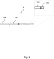
- the wire 4 can be inserted into a patient's vasculature and traversed to bring its distal end to the location of a lesion. Once a complex lesion is encountered that resists the wire 4 crossing it, the activation unit 2 can be coupled to the wire 4 at a suitable longitudinal location. When activated, the activation unit 2 transmits ultrasonic vibrations to and along the wire 4, enhancing the ability of the wire 4 to cross the lesion through ablation and other mechanisms. The wire 4 thereby serves as a crossing wire for crossing through an occlusion in a blood vessel and can then remain in situ to serve as a guide wire for delivering subsequent therapeutic devices to treat the lesion.
- the diameter of the distal section of the wire 4 will determine the flexibility of the wire 4 and its ability easily to conform to the shape of the anatomy through which it is intended to pass.
- a distal section of a diameter of 0.005" to 0.007" combines flexibility with the ability to excavate occlusive material.
- the activation unit 2 includes user controls 6 and optionally also a display.
- the activation unit 2 further comprises a distal hand toggle 8 that a user can turn about the central longitudinal axis of the unit 2 and of the wire 4.
- the activation unit 2 can slide over the wire 4 and can be coupled to the wire 4 at a plurality of longitudinally spaced locations by applying torque to turn the toggle 8.
- the toggle 8 acts on a coupling such as a collet within the activation unit 2 that surrounds and is coaxial with the wire 4.
- the toggle 8 grips the wire 4 to transmit ultrasonic energy from an integrated ultrasonic transducer within the activation unit 2, optionally via an amplifier horn that is coupled to the transducer.
- the wire 4 could be coupled directly to the transducer in some embodiments, in which case the horn may be omitted.
- FIG. 1 shows a disaggregated arrangement in which an ultrasonic signal generator 10 is separate from the activation unit 2.
- the ultrasonic signal generator 10 is connected to the activation unit 2 by a connector cable 12.
- the ultrasonic signal generator 10 may be incorporated into the housing of the activation unit 2.
- the example shown in Figure 1 has an externally powered ultrasonic signal generator 10 and therefore comprises a power cable 14 that connects to an external source of electrical power.
- Alternative embodiments may be powered by internal batteries, which can, e.g., be incorporated into the ultrasonic signal generator unit 10 or into the activation unit 2.
- the components of the system are preferably portable and are more preferably hand-held.
- the components may be wireless, rechargeable, reusable, and recyclable.
- Any external cable 12, 14 for conveying power or signals may be coupled through a slip ring to allow free rotation of the cable 12, 14 and to avoid entanglement with the wire 4 or it may provide a conduit for the proximal portion of the wire 4.
- a semi-automated control system can control or modulate the signal from the generator 10 applied to the transducer and horn of the activation unit 2 and hence to the crossing wire 4 based on feedback from the wire-tissue interaction in order to control the signal being transmitted to adjust for losses due to damping or increased resistance or modulating applied force.
- Visual and haptic feedback indicators can offer visual, audio and/ or tactile feedback to the user regarding the status of the device, the nature of the tissue being ablated and indicate the level of force that can be applied to effect ablation and disruption of the tissue and progression of the crossing wire.
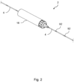
- Figure 2 shows how the wire 4 may be etched or otherwise marked with a series of optimum zonal markings 92 to guide the user in choosing lengths of the wire 4 that encourage distal activation.
- the user can then align the coupling of the activation unit 2 with the zonal markings 92 on the wire 4, optionally using other markings appropriately located on the housing 18 of the activation unit 2.
- This approach applies to both straight-through embodiments in which a proximal portion of the wire 4 emerges from the housing 18 of the activation unit 2 axially and other embodiments in which a proximal portion of the wire 4 emerges laterally at a position along the length of the housing 18.
- the markings 92 address a challenge in the control of the system, namely the manner in which ultrasonic energy is coupled to the wire and the importance at locating the point of connection at specific regions that will couple best.
- the markings 92 placed on the proximal segment of the wire 4 ensure that this alignment is clear to the physician. These markings 92 also facilitate the physician reconnecting the activation unit 2 to the wire 4 at different locations during a procedure.
- the markings 92 may be aligned with a reference point on the activation unit 2, for example a reference point on a strain relief feature at the distal end of the housing 18 to denote the best point of location.
- Visualisation of the markings 92 may be improved by adding illumination and/or a transparent or translucent window to the activation unit 2, for example positioned on a distal strain relief feature of the unit 2.
- the markings 92 are apt to be applied by laser etch beading or other means, such as the application of a coating and/or a jacket, to mark the surface of the wire 4 in a way that allows the user to discriminate the best points of connection along the length of the wire 4. It is considered that modifying the oxide surface layer or the finish of the wire 4 is the best way to achieve this.
- the period or longitudinal spacing of these markings will be ⁇ /2 and their length will be a function of the efficiency of coupling energy into the wire 4, which is also a function of its mechanical and dimensional properties.
- the markings 92 on the wire 4 could indicate any of a plurality of lengths where the distal section of the wire 4 emerging from the housing 18 of the activation unit is at or near a resonant length and the proximal section is not at a resonant length.
- attachment zone markers 92 are positioned optimally on the wire 4 such that, when coupled to the acoustic source, the length of the distal portion from the coupling point to the distal tip is equal to a resonant length whereas the length of the proximal portion from the coupling point to the proximal tip is equal to a non-resonant length.
- these markings 92 may be located at positions tailored to the system to take into account bends and other design features that may affect the resonant response.
- the distal length of the wire 4 from the distal tip to where the activation unit 2 is coupled to the wire 4 should be an odd multiple of a quarter wavelength of the ultrasonic wave. This creates a standing wave in the wire with a vibrating antinode at the distal tip, hence maximising the amplitude of vibration at the distal tip.
- a wire 4 of the invention When coupled to the ultrasonic transducer 20 in the activation unit 2, a wire 4 of the invention undergoes axial ultrasonic vibration and can be considered as a fixed-free rod under longitudinal or axial vibration.
- the wire 4 can be considered as two fixed-free rods undergoing longitudinal axial vibration. One rod extends distally and the other rod extends proximally from the activation unit 2.
- a particular nitinol alloy has a speed of sound of approximately 3400 m/s.
- the wavelength ⁇ can be calculated to be approximately 85 mm. Resonant lengths can therefore be determined and marked at optimum positions on the wire 4. The wavelength further impacts on the selection of taper locations and taper lengths along the wire 4.
- Figures 3 to 7 show various preferred and optional features of the wire 4.
- the wire 4 has features to allow it to integrate with the handheld activation unit 2.
- location markers are provided to guide optimal positioning and attachment of the activation unit 2 to facilitate attachment and release at a plurality of longitudinal locations.
- a series of optimum attachment locations are etched or otherwise marked on the wire 4 to guide the user in locating and selecting the optimum attachment locations for distal ultrasonic transmission from the activation unit 2.
- the housing 18 of the activation unit 2 can also have a marker that can be aligned with the wire 4 marking prior to coupling.
- the wire 4 functions as an excavator, not just at its tip but also along part of its length.
- the wire 4 has a distal land length that acts radially as a lateral excavation device for opening an aperture.
- the wire may have distal shaped lengths to amplify radial excavation.
- the wire 4 may therefore be fabricated from sections welded together end-to-end.
- a proximal section may be machined as a standard diameter to provide for amplification as well as to provide a standard connection for a proximally-loaded activation unit 2.
- the proximal section can be welded to one of a selection of different diameter wires that may have custom distal ends and tips.
- sections may be chosen and combined in various ways. This beneficially reduces the requirement to hold stock of various wire diameters as sections of a few different wire diameters may be assembled to produce wires 4 of many required configurations. Welding the proximal segment to the distal segment facilitates more efficient manufacturing and more efficient transmission if post-processing is performed on the wire, and allows welding of different materials to a proximal NiTi base if desired.
- tapers can be chosen to begin at lengths equal or nearly equal to multiples of the half wavelength of the wire system. This places the start of the tapers at anti-nodes of a standing wave in the wire 4, where the amplitude of vibration is at a maximum.
- the lengths of the tapered sections are chosen to be equal or nearly equal to half wavelengths of the resonant system.
- welds or joins should be located at longitudinal positions where the stress is at a minimum. As the welds or joins are at locations of low stress, the loads applied to them in the course of activation of the wire will not lead to catastrophic fatigue failure.
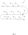
- the wire 4 shown in Figure 3 comprises a proximal section 124, a central or intermediate section 128 and a distal excavating section 130 for crossing a lesion.
- the intermediate section 128 is narrower than the proximal section 124 but is wider than the distal section 130.
- the intermediate section 128 is therefore joined to the proximal section 124 by a tapering proximal transition 132 and to the distal section by a tapering distal transition 134.
- Each section is welded to the next by a weld 122 on the proximal side of the respective transitions.
- the proximal section 124 has a series of longitudinally spaced zonal markings 92 like those in Figure 2 to guide the user in choosing wire lengths that encourage distal activation and that discourage proximal activation.
- the wire 4 further comprises radio opaque marker bands 136 to aid tracking of the intermediate 128 and distal sections 130 within a patient's anatomy during the procedure. These various markers 136 are apt to be created by plasma vapour deposition, atomic layer deposition or sputtering, for example of sputtered gold, to resist ultrasonic loading.
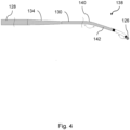
- the distal tip 126 is inclined further than the angled leg 140 away from the general axis of the wire 4.
- the distal tip 126 and the angled leg 140 are both inclined in broadly the same direction away from the general axis of the wire 4.
- the inclination of the distal tip 126 is closer than the angled leg 140 to the general axis of the wire 4. Potentially, the distal tip 126 could even be approximately parallel to the general axis of the wire 4 in the remainder of the distal section 130.
- the total length of the distal portion of the wire 4 from the distal tip 126 to the connection point or coupling of the activation unit 2 may be equal to the resonant length for the wire 4.
- the taper length is equal to a multiple of half the wavelength.
- the diameters of the various sections of the wire 4 are chosen for an optimal balance between pushability and trackability, in addition to being able to allow follow-on devices of standard dimensions to use the wire 4 as a guidewire.
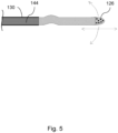
- Figure 5 shows that the wire 4 may have a distal coil or polymer jacket 144 attached or bonded over the distal section 130.
- the jacket shown here terminates distally just before a bend in the wire 4 that facilitates deflection of the distal tip 126.
- the distal tip 126 of the wire 4 may be coated or processed to harden the surface or increase its ablative properties.
- Figures 6 and 6a show a wire 4 that has a substantially straight proximal section or land 124, a distally-tapering intermediate section 130 and a substantially straight excavating part or land providing a distal tip portion 126 for crossing a lesion.
- the distal tip portion 126 has a smaller diameter than the proximal section 124.
- the proximal section 124 may have a diameter of 0.43mm and the distal tip portion 126 may have a diameter of 0.18mm or 0.25mm.
- the taper in the intermediate section 130 is slight and so is greatly exaggerated in these drawings.
- the tapering intermediate section 130 may extend over a multiple of ⁇ in length or a fraction of ⁇ in length, that fraction preferably having with a numerator of 1 and an even denominator - for example in the sequence 1/2, 1/4, 1/8... - whereas the distal tip portion 126 may have a length of ⁇ /2 or a multiple of ⁇ /2 or a fraction of ⁇ /2 such as ⁇ /4.
- the overall geometry of the wire 4 including its nominal diameter and length and the driving frequency of the system are determined by the characteristic speed of sound in the material of the wire. This characteristic is a function of that material's properties and its geometry.
- the dimensions of the straight and tapered sections of the wire are machined at functional intervals of wavelength.
- ⁇ , ⁇ /2 and ⁇ /4 are determined to be 84mm, 42mm and 21mm in this example.
- the chosen frequency will produce harmonics along the length of the wire and the loading of the tip of the wire will assist in establishing standing waves for non-characteristic lesions.
- the distal section 126 can be tapered or can be uniform in diameter along its length. The system may produce lateral and longitudinal displacements over a range of frequencies away from that of the drive frequency, often occurring at sub-harmonics of the frequency in the distal section 126.
- a wire with a core cross section diameter of 0.43 mm has a tapered section 130 optimally located to transition to a distal wire diameter to 0.18 mm.
- the lengths of each section of the wire can be chosen to have a longitudinal resonant mode at or near the driving frequency, such as 40 kHz, with strong sub-harmonics at or near 20kHz, 10 kHz or others.
- the driving frequency such as 40 kHz
- additional lower-frequency lateral vibrations may be induced through a cantilever action.
- the overall length of the wire may be a function of an odd multiple of ⁇ /4.
- the active length being the distance from the proximal connection point to the distal tip of the wire, may also be a function of an odd multiple of ⁇ /4.
- the purpose of the tapered transition 130 is to provide gain and to sustain the transmission of energy through the wire.
- the tapered section will also affect how a lateral mode of displacement may be established in the distal land section 126 of the wire.
- the point at which the taper is introduced may also assist with facilitating a change of materials between one part of the wire and another, which could create a differential in wavelength between the distal and proximal segments.
- Tapered transitions may vary in diameter in a stepped, exponential, radial or linear manner.
- the change in the cross-sectional area represents a level of gain in both lateral and longitudinal displacement amplitudes in the wire.
- the length and the diameter of the distal section 126 will determine the mode and magnitude of displacement in axial and radial directions.
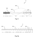
- Figure 6 shows that the distal section 126 of the wire 4, once activated, moves in a primary longitudinal mode, moving in and out, and also in a radial direction which maps out and excavates a greater volume at the distal end through the longitudinal movement of the wire 4.
- the distal section 126 of the wire 4 is also seen to move through lateral and undulating movements at or near the drive frequency and secondary modes of differential harmonics, dependent on the activating frequency and also the length of the distal section 126.
- These wave forms may interfere with each other and be more or less effective in excavating material at different moments.
- Figure 6 further shows how the distal end section 126 of the wire 4 may excavate an aperture whose diameter is greater than the diameter of the wire and so create a larger lumen through which therapies may be introduced to a lesion.
- a catheter sleeve or a polymer jacket 144 terminates before an unjacketed distal section 130 of the wire.
- the distal section 126 of the wire 4 once activated, moves in a primary longitudinal mode, moving in and out, and also in a radial direction which maps out and excavates a greater volume at the distal end through the longitudinal movement of the wire 4.
- the distal section 126 of the wire 4 is also seen to move in other modes through lateral and undulating movements under the resonant wave 146 and secondary modes of differential harmonics, dependent on the activating frequency, the length of the distal section and the tortuosity of the anatomy.
- the wire 4 when activated with ultrasonic energy, acts as an excavation tool for excavating material distal to the distal tip of the wire 4 by virtue of longitudinal movement and then through the offset translation or lateral motion of the wire 4 within the vasculature which provides a lateral offset.
- the wire 4 abrades the inner surface of the occlusion not just at its distal tip but also along some of its length extending proximally from the distal tip and so forms a wider aperture for the passage of follow-up therapeutic devices over the wire 4.
- the lateral displacement continues to excavate within the body of the lesion and so forms a larger lumen.
- the wire 4 may not necessarily be shaped or angled at its tip but where it is shaped or angled at its tip, the angle is chosen carefully. If the angle of the tip 126 is too great, it will create a larger lever arm and so could fatigue the wire 4 excessively; conversely if the angle of the tip 126 is too small, then the wire 4 may not be steerable effectively.
- Figure 7 shows that the tip 126 may be offset from the longitudinal axis of the wire 4 by about 15° to 45°, allowing the tip 126 to disrupt and excavate a greater volume of a lesion.
- the tip 126 is suitably heat-treated, for example at over 500°C for less than 10 minutes, in order to create a microstructure that is reliably resistant to crack propagation and hence to fatigue.
- Figures 8a and 8b show how visibility of the location of the wire 4 in the patient's body may be enhanced by the use of marker bands 194, for example of gold.
- marker bands 194 may, for example, be fixed at locations close to (for example, about 3mm from) the distal tip 126 of the wire 4 and also from the distal end of the proximal section 184, just before the start of the tapered intermediate section 186.
- the marker bands 194 are placed at locations of minimal load in use of the wire 4. This minimises the possibility that the marker bands 194 could become detached or that the wire 4 could fail at those locations.
- the marker bands 194 are apt to be flush-fitted into circumferential grooves that are ground around the wire 4.
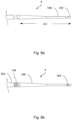
- Figure 9 shows a variant in which the distal tip 126 of the wire 4 is rounded, with no sharp transitions.
- the proximal section 184 may be 1800mm long
- the tapered intermediate section 186 may be 84mm long
- the distal section 188 may be 10mm long.
- marker bands 194 encircle the wire 4 close to the distal tip 126 of the wire 4 and the distal end of the proximal section 184.
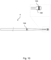
- Figures 10 and 11 show other variants of the wire 4 that each have a bulbous distal tip 198, which is rounded to avoid sharp transitions but could instead be chamfered or faceted, preferably with obtuse angles between facets, with distally-converging facets that ease passage of the wire through the anatomy. Enlargements such as bulbs may be located at the distal tip and/or be spaced slightly from the distal tip, and could cover a radiopaque coil or other materials.
- the bulbous tip 198 may, for example, be 3mm to 4mm in length and may have a diameter of just over 0.4mm, or from 0.010" to 0.035" for example.
- the wire shown in Figure 10 is otherwise analogous to the wire 4 shown in Figure 9 .
- the wires 4 shown in Figures 10 and 11 have circumferential marker bands 194 that may be flush-fitted into circumferential grooves ground around the wire 4.
- the bulbous tip 198 may be encircled by one of the marker bands 194.
- the wire has a proximal portion that comprises a straight section 200 and a distally tapering section 202.
- the straight section 200 may have a ridged or otherwise textured surface as shown, to improve engagement with an activation device.
- the proximal portion is welded to an intermediate portion that constitutes most of the length of the wire 4.
- the intermediate portion also comprises a straight section 204 and a short distally tapering section 206.
- a marker band 194 is shown encircling the straight section 204 close to the distally tapering section 206 of the intermediate portion 194.
- a short, narrow distal section 208 extends distally from the intermediate portion 186 to the bulbous tip 198.
- jacketing the wire 4 below or beyond a resonant or harmonic length so that the distal edge 148 of the jacket 144 does not coincide with a resonant or harmonic length, hinders formation of an aperture.
- jacketing the wire 4 up to a resonant or harmonic length so that the distal edge 148 of the jacket 144 substantially coincides with a resonant or harmonic length, allows the wire 4 to excavate a larger aperture.
- Figures 13a, 13b, and 13c show a selection of arrangements of the distal tip 126.
- Figure 13a shows the wire 4 encircled by a radio-opaque band 136 and provided with a rounded bull tip 150, for example of beryllium.
- Figure 13b shows a radio-opaque coil 151 welded around the distal tip section 126 of the wire 4.
- Figure 13c shows an oversized beryllium tip 152 to increase effectiveness when crossing long calcific sections.
- the distal tip section 126 may be heat-treated to increase its fatigue resistance.
- Figures 14a, 14b, 14c show other arrangements of the distal tip 126.
- Figure 14a shows a looped tip 154 with an outer surface that is coated or otherwise modified to optimize drilling or excavation over the loop rather than being confined to a tip. The loop may also aid navigation to the site of a blockage.
- Figure 14b shows a diamond-coated tipped burr 156.
- Figure 14c shows a drilling end tip 158 or segment that is coated with a diamond and/or carbide coating. Coatings and hardened materials such as these provide for aggressive machining of lesions.
- wires 4 of the invention are apt to be made of superelastic alloys, such as nitinol (nickel-titanium), which are known to have preferential properties in the transmission of ultrasound while providing a balance of flexibility and pushability.
- superelastic alloys such as nitinol (nickel-titanium)
- Linear elastic nitinol arising from advances in processing alloys of nickel and titanium may also be used for wires of the invention, as can beta titanium.
- Surface finishes and coatings applied to the wires 4 may include resilient fluoropolymers and hydrophilic coatings to reduce friction.
- a coating may be provided along a discrete segment of the wire, such as by coating a mid-section of the length of the wire to leave distal and proximal end portions of the wire uncoated for excavation and for clamping an activation unit, respectively. Continuous and broken segments of coating along the length of the wire may allow for selective clamping and unclamping of an activation unit at desired positions.
- PTFE or alternative polymeric jackets may be employed to reduce friction and risk of damage to the interior of a guide catheter
- Surface modification may involve addition of striations or serrations into the surface of the distal end portion to bite further into calcific lesions so as to assist excavation and resist damage.
- Such formations may be directional so to take advantage of the direction of motion and to amplify the efficiency of cutting or abrasion of the occluding material. Nevertheless, individual formations may have a smooth rather than sharp contours so as not to damage the vessel wall.
- materials may be applied to the wire to create an additional abrading surface to assist in excavating material. Such materials may usefully reduce the area of the wire that is in contact with the lesion to promote cutting and to prevent calcified material blocking vibration and movement of the wire.
- Drawn filled tubing may be employed, in which a NiTi core is surrounded by a second metal that has different properties, for example stainless steel. As the relative thickness of that secondary layer can be controlled, it could be used to create marker bands for coupling or shaping of the wire, or for promoting lateral damping.
Landscapes
- Health & Medical Sciences (AREA)
- Surgery (AREA)
- Life Sciences & Earth Sciences (AREA)
- Engineering & Computer Science (AREA)
- Medical Informatics (AREA)
- Molecular Biology (AREA)
- Veterinary Medicine (AREA)
- Public Health (AREA)
- Biomedical Technology (AREA)
- Heart & Thoracic Surgery (AREA)
- General Health & Medical Sciences (AREA)
- Nuclear Medicine, Radiotherapy & Molecular Imaging (AREA)
- Animal Behavior & Ethology (AREA)
- Vascular Medicine (AREA)
- Mechanical Engineering (AREA)
- Orthopedic Medicine & Surgery (AREA)
- Oral & Maxillofacial Surgery (AREA)
- Pathology (AREA)
- Surgical Instruments (AREA)
- Media Introduction/Drainage Providing Device (AREA)
Applications Claiming Priority (4)
| Application Number | Priority Date | Filing Date | Title |
|---|---|---|---|
| PCT/EP2019/080449 WO2020094747A2 (en) | 2018-11-06 | 2019-11-06 | Treatment of ischaemia |
| GBGB2006665.0A GB202006665D0 (en) | 2020-05-05 | 2020-05-05 | Treatment of ischaemia |
| PCT/EP2020/081399 WO2021089859A1 (en) | 2019-11-06 | 2020-11-06 | Wire for an endovascular apparatus |
| EP20816410.3A EP4054446B1 (de) | 2019-11-06 | 2020-11-06 | Draht für ein endovaskuläres gerät |
Related Parent Applications (1)
| Application Number | Title | Priority Date | Filing Date |
|---|---|---|---|
| EP20816410.3A Division EP4054446B1 (de) | 2019-11-06 | 2020-11-06 | Draht für ein endovaskuläres gerät |
Publications (3)
| Publication Number | Publication Date |
|---|---|
| EP4295792A2 true EP4295792A2 (de) | 2023-12-27 |
| EP4295792A3 EP4295792A3 (de) | 2024-02-21 |
| EP4295792B1 EP4295792B1 (de) | 2026-02-04 |
Family
ID=71080530
Family Applications (5)
| Application Number | Title | Priority Date | Filing Date |
|---|---|---|---|
| EP23195560.0A Active EP4295792B1 (de) | 2019-11-06 | 2020-11-06 | Endovaskuläres gerät |
| EP20816410.3A Active EP4054446B1 (de) | 2019-11-06 | 2020-11-06 | Draht für ein endovaskuläres gerät |
| EP20816409.5A Active EP4054445B1 (de) | 2019-11-06 | 2020-11-06 | Endovaskuläre vorrichtung |
| EP24221911.1A Pending EP4501259A3 (de) | 2020-05-05 | 2021-05-05 | Behandlung von ischämie |
| EP21728438.9A Withdrawn EP4146095A1 (de) | 2020-05-05 | 2021-05-05 | Behandlung von ischämie |
Family Applications After (4)
| Application Number | Title | Priority Date | Filing Date |
|---|---|---|---|
| EP20816410.3A Active EP4054446B1 (de) | 2019-11-06 | 2020-11-06 | Draht für ein endovaskuläres gerät |
| EP20816409.5A Active EP4054445B1 (de) | 2019-11-06 | 2020-11-06 | Endovaskuläre vorrichtung |
| EP24221911.1A Pending EP4501259A3 (de) | 2020-05-05 | 2021-05-05 | Behandlung von ischämie |
| EP21728438.9A Withdrawn EP4146095A1 (de) | 2020-05-05 | 2021-05-05 | Behandlung von ischämie |
Country Status (8)
| Country | Link |
|---|---|
| US (7) | US11660104B2 (de) |
| EP (5) | EP4295792B1 (de) |
| JP (5) | JP7481035B2 (de) |
| CN (4) | CN114901162B (de) |
| AU (2) | AU2020379232A1 (de) |
| ES (2) | ES2960194T3 (de) |
| GB (1) | GB202006665D0 (de) |
| WO (3) | WO2021089859A1 (de) |
Families Citing this family (8)
| Publication number | Priority date | Publication date | Assignee | Title |
|---|---|---|---|---|
| GB202006665D0 (en) | 2020-05-05 | 2020-06-17 | Versono Medical Ltd | Treatment of ischaemia |
| GB202020065D0 (en) | 2020-12-17 | 2021-02-03 | Versono Medical Ltd | Acoustic characterisation of the effects on intralumenal wires |
| IT202100024116A1 (it) * | 2021-09-20 | 2023-03-20 | Enki Srl | Dispositivo e metodo di sgancio di un filo da un tubo |
| CN119012977A (zh) | 2021-12-17 | 2024-11-22 | 韦尔索诺医疗有限公司 | 用于确定身体中的结构的状况的装置和方法 |
| US20250057553A1 (en) * | 2021-12-22 | 2025-02-20 | Bard Peripheral Vascular, Inc. | Catheter devices with damping assemblies for core wires |
| EP4496615A4 (de) * | 2022-03-22 | 2026-03-25 | Univ Rutgers | Neuroaspirationskatheter für thrombektomie |
| CN116919535B (zh) * | 2022-10-13 | 2024-05-07 | 以诺康医疗科技(苏州)有限公司 | 一种超声手术刀头 |
| US20240207574A1 (en) * | 2022-12-21 | 2024-06-27 | Corindus, Inc. | Torque lmiting actuator for elongated medical device torquer |
Citations (9)
| Publication number | Priority date | Publication date | Assignee | Title |
|---|---|---|---|---|
| US3433226A (en) | 1965-07-21 | 1969-03-18 | Aeroprojects Inc | Vibratory catheterization apparatus and method of using |
| US4979939A (en) | 1984-05-14 | 1990-12-25 | Surgical Systems & Instruments, Inc. | Atherectomy system with a guide wire |
| US5427118A (en) | 1993-10-04 | 1995-06-27 | Baxter International Inc. | Ultrasonic guidewire |
| US5971949A (en) | 1996-08-19 | 1999-10-26 | Angiosonics Inc. | Ultrasound transmission apparatus and method of using same |
| US6450975B1 (en) | 1999-12-30 | 2002-09-17 | Advanced Cardiovascular Systems, Inc. | Ultrasonic transmission guide wire |
| US6855123B2 (en) | 2002-08-02 | 2005-02-15 | Flow Cardia, Inc. | Therapeutic ultrasound system |
| US9282984B2 (en) | 2006-04-05 | 2016-03-15 | Flowcardia, Inc. | Therapeutic ultrasound system |
| US9629643B2 (en) | 2006-11-07 | 2017-04-25 | Flowcardia, Inc. | Ultrasound catheter having improved distal end |
| WO2020094747A2 (en) | 2018-11-06 | 2020-05-14 | Versono Medical Limited | Treatment of ischaemia |
Family Cites Families (79)
| Publication number | Priority date | Publication date | Assignee | Title |
|---|---|---|---|---|
| US5284148A (en) | 1989-05-16 | 1994-02-08 | Hewlett-Packard Company | Intracavity ultrasound diagnostic probe using fiber acoustic waveguides |
| FR2653040B1 (fr) * | 1989-10-18 | 1994-05-13 | Aerospatiale Ste Nationale Indle | Dispositif de percussion a ultrasons. |
| US5248296A (en) * | 1990-12-24 | 1993-09-28 | Sonic Needle Corporation | Ultrasonic device having wire sheath |
| US5542917A (en) * | 1991-01-11 | 1996-08-06 | Baxter International, Inc. | Ultrasound delivery catheters incorporating improved distal tip construction |
| US5447509A (en) | 1991-01-11 | 1995-09-05 | Baxter International Inc. | Ultrasound catheter system having modulated output with feedback control |
| US5161534A (en) | 1991-09-05 | 1992-11-10 | C. R. Bard, Inc. | Tool for manipulating a medical guidewire |
| US5269297A (en) * | 1992-02-27 | 1993-12-14 | Angiosonics Inc. | Ultrasonic transmission apparatus |
| US5382228A (en) * | 1992-07-09 | 1995-01-17 | Baxter International Inc. | Method and device for connecting ultrasound transmission member (S) to an ultrasound generating device |
| US5524635A (en) | 1992-09-14 | 1996-06-11 | Interventional Technologies Inc. | Apparatus for advancing a guide wire |
| US5243997A (en) * | 1992-09-14 | 1993-09-14 | Interventional Technologies, Inc. | Vibrating device for a guide wire |
| US5314408A (en) * | 1992-11-13 | 1994-05-24 | Cardiovascular Imaging Systems, Inc. | Expandable member for a catheter system |
| US5397293A (en) * | 1992-11-25 | 1995-03-14 | Misonix, Inc. | Ultrasonic device with sheath and transverse motion damping |
| SE9302356D0 (sv) * | 1993-07-07 | 1993-07-07 | Siemens-Elema Ab | Koppling foer selektiv foerbindning av roerledningar samt strypningsanordning |
| US5507738A (en) * | 1994-08-05 | 1996-04-16 | Microsonic Engineering Devices Company, Inc. | Ultrasonic vascular surgical system |
| US6241703B1 (en) * | 1996-08-19 | 2001-06-05 | Angiosonics Inc. | Ultrasound transmission apparatus having a tip |
| US5846218A (en) | 1996-09-05 | 1998-12-08 | Pharmasonics, Inc. | Balloon catheters having ultrasonically driven interface surfaces and methods for their use |
| US6010449A (en) | 1997-02-28 | 2000-01-04 | Lumend, Inc. | Intravascular catheter system for treating a vascular occlusion |
| US5908395A (en) | 1997-03-17 | 1999-06-01 | Advanced Cardiovascular Systems, Inc. | Vibrating guidewire |
| US6577042B2 (en) | 1997-05-19 | 2003-06-10 | Angiosonics Inc. | Feedback control system for ultrasound probe |
| US6007514A (en) * | 1997-09-30 | 1999-12-28 | Nita; Henry | Ultrasound system with pathfinding guidewire |
| US6077282A (en) * | 1997-10-27 | 2000-06-20 | Shturman Cardiology Systems, Inc. | Rotational atherectomy device with exchangeable drive shaft cartridge |
| US20040024393A1 (en) * | 2002-08-02 | 2004-02-05 | Henry Nita | Therapeutic ultrasound system |
| US6251110B1 (en) * | 1999-03-31 | 2001-06-26 | Ethicon Endo-Surgery, Inc. | Combined radio frequency and ultrasonic surgical device |
| US6758830B1 (en) * | 1999-05-11 | 2004-07-06 | Atrionix, Inc. | Catheter positioning system |
| US6695782B2 (en) * | 1999-10-05 | 2004-02-24 | Omnisonics Medical Technologies, Inc. | Ultrasonic probe device with rapid attachment and detachment means |
| US20050119679A1 (en) * | 1999-10-05 | 2005-06-02 | Omnisonics Medical Technologies, Inc. | Apparatus and method for an ultrasonic medical device to treat chronic total occlusions |
| JP2002085420A (ja) * | 2000-09-19 | 2002-03-26 | Olympus Optical Co Ltd | 超音波凝固切開装置とその方法 |
| US7211044B2 (en) | 2001-05-29 | 2007-05-01 | Ethicon Endo-Surgery, Inc. | Method for mapping temperature rise using pulse-echo ultrasound |
| US7744537B2 (en) | 2001-08-20 | 2010-06-29 | Japan Science And Technology Agency | Ultrasonic method and system for characterizing arterial tissue using known elasticity data |
| US7831297B2 (en) * | 2003-05-24 | 2010-11-09 | Scottsdale Medical Devices, Inc. | Guide wire torque device |
| US8133236B2 (en) * | 2006-11-07 | 2012-03-13 | Flowcardia, Inc. | Ultrasound catheter having protective feature against breakage |
| US7137963B2 (en) * | 2002-08-26 | 2006-11-21 | Flowcardia, Inc. | Ultrasound catheter for disrupting blood vessel obstructions |
| US20040176686A1 (en) * | 2002-12-23 | 2004-09-09 | Omnisonics Medical Technologies, Inc. | Apparatus and method for ultrasonic medical device with improved visibility in imaging procedures |
| WO2004096061A1 (en) * | 2003-03-25 | 2004-11-11 | Omnisonics Medical Technologies, Inc. | Ultrasonic probe used with a pharmacological agent |
| US8734368B2 (en) * | 2003-09-04 | 2014-05-27 | Simon Fraser University | Percussion assisted angiogenesis |
| CN100479759C (zh) | 2004-11-30 | 2009-04-22 | 全音速医学技术有限公司 | 具有变频驱动的超声医疗设备 |
| EP1890757B1 (de) | 2005-05-11 | 2013-02-27 | Eyoca Medical Ltd. | Gerät zur öffnung von gefässverschlüssen |
| US20070066978A1 (en) | 2005-09-06 | 2007-03-22 | Schafer Mark E | Ultrasound medical devices and related methods |
| US20070073333A1 (en) * | 2005-09-26 | 2007-03-29 | Medtronic Vascular, Inc. | Low profile filter assembly for distal embolic protection |
| US20070225749A1 (en) | 2006-02-03 | 2007-09-27 | Martin Brian B | Methods and devices for restoring blood flow within blocked vasculature |
| ITRE20060152A1 (it) * | 2006-12-15 | 2008-06-16 | Franco Baldi | Perfezionamenti a rilevatore di ostacoli a collimazione e focalizzazione dell'onda emessa. |
| JP2009000586A (ja) | 2007-06-19 | 2009-01-08 | Terumo Corp | 超音波発生装置および超音波発生システム |
| US8226709B2 (en) * | 2007-10-19 | 2012-07-24 | Cordis Corporation | Method and system for plicating tissue in a minimally invasive medical procedure for the treatment of mitral valve regurgitation |
| US9775632B2 (en) * | 2008-05-23 | 2017-10-03 | Medinol Ltd. | Method and device for recanalization of total occlusions |
| WO2010056558A2 (en) * | 2008-10-31 | 2010-05-20 | Greatbatch Ltd. | Mri conditionally safe lead extension and methods |
| AU2010273651B2 (en) * | 2009-07-15 | 2015-12-03 | Ethicon Endo-Surgery, Inc. | Electrosurgery generator for ultrasonic surgical instruments |
| ES2480422T3 (es) | 2009-08-14 | 2014-07-28 | Ethicon Endo-Surgery, Inc. | Aparato quirúrgico ultrasónico |
| US20130345617A1 (en) * | 2009-10-06 | 2013-12-26 | Michael P. Wallace | Methods and devices for removal of tissue, blood clots and liquids from the patient |
| AU2011214066B2 (en) | 2010-02-09 | 2014-09-11 | Medinol Ltd. | Device for traversing vessel occlusions and method of use |
| CN202654235U (zh) * | 2012-05-22 | 2013-01-09 | 刘建军 | 超声清石碎石的手柄 |
| RU2640564C2 (ru) | 2012-08-02 | 2018-01-09 | Бард Периферэл Васкьюлар | Ультразвуковая катетерная система |
| WO2014024550A1 (ja) * | 2012-08-07 | 2014-02-13 | オリンパスメディカルシステムズ株式会社 | 超音波プローブ及び超音波プローブの製造方法 |
| US9339284B2 (en) * | 2012-11-06 | 2016-05-17 | Med-Sonics Corporation | Systems and methods for controlling delivery of ultrasonic energy to a bodily tissue |
| US9592027B2 (en) | 2013-03-14 | 2017-03-14 | Volcano Corporation | System and method of adventitial tissue characterization |
| WO2014188509A1 (ja) * | 2013-05-21 | 2014-11-27 | テルモ株式会社 | カテーテル |
| EP3050528A4 (de) * | 2013-09-27 | 2017-06-21 | Olympus Corporation | Sondeneinheit, behandlungswerkzeug und behandlungssystem |
| US10463424B2 (en) * | 2014-03-11 | 2019-11-05 | Medtronic Ardian Luxembourg S.A.R.L. | Catheters with independent radial-expansion members and associated devices, systems, and methods |
| WO2016081026A1 (en) * | 2014-11-19 | 2016-05-26 | C.R. Bard, Inc. | Ultrasound catheter and system with multiple function modes |
| WO2016081025A1 (en) | 2014-11-19 | 2016-05-26 | C.R. Bard, Inc. | Ultrasound transducer system for use with an ultrasound catheter |
| US9763684B2 (en) * | 2015-04-02 | 2017-09-19 | Med-Sonics Corporation | Devices and methods for removing occlusions from a bodily cavity |
| DE112016003419T8 (de) * | 2015-07-29 | 2018-08-02 | Actuated Medical, Inc. | Vorrichtungen zum beseitigen von blockierungen in künstlichen und natürlichen lumina |
| US20170215837A1 (en) | 2016-01-29 | 2017-08-03 | Boston Scientific Limited | Acoustic sensor based guidewire |
| EP3451961B1 (de) * | 2016-05-02 | 2024-12-04 | Affera, Inc. | System umfassend einen katheter und eine expandierbare elektrode |
| CN205852411U (zh) * | 2016-07-31 | 2017-01-04 | 山西大同大学 | 一种新型回转非接触超声电能传输装置 |
| US10357262B2 (en) * | 2016-11-14 | 2019-07-23 | C. R. Bard, Inc. | Systems and methods to modify intravascular lesions |
| US20180140321A1 (en) * | 2016-11-23 | 2018-05-24 | C. R. Bard, Inc. | Catheter With Retractable Sheath And Methods Thereof |
| EP3330728B1 (de) * | 2017-05-22 | 2020-10-21 | Siemens Healthcare GmbH | Verfahren zur gefässdarstellung mit hilfe einer mr-anlage |
| US10820920B2 (en) * | 2017-07-05 | 2020-11-03 | Ethicon Llc | Reusable ultrasonic medical devices and methods of their use |
| CN111032156A (zh) * | 2017-08-16 | 2020-04-17 | 皇家飞利浦有限公司 | 一次性治疗性超声波装置 |
| US10987247B2 (en) * | 2017-10-18 | 2021-04-27 | Jesus Moreno | Opthalmic microsurgical instrument |
| US20190125302A1 (en) | 2017-10-31 | 2019-05-02 | Koninklijke Philips N.V. | Accelerometer in handle for ultrasound medical imaging device |
| CN111491577B (zh) * | 2017-11-10 | 2023-12-01 | 巴德股份有限公司 | 用于导管的散热器以及该散热器的系统和方法 |
| US11234676B2 (en) * | 2018-01-29 | 2022-02-01 | Elekta Ltd. | Probe holder for ultrasound imaging device |
| EP3745969A4 (de) | 2018-02-03 | 2021-10-13 | Caze Technologies | Chirurgische systeme mit erfassungs- und maschinenlernfähigkeiten und verfahren dafür |
| CN209173124U (zh) * | 2018-07-11 | 2019-07-30 | 杜学军 | 一种自动浅表静脉穿刺置管设备 |
| US20200114041A1 (en) * | 2018-10-15 | 2020-04-16 | Avent, Inc. | Systems and methods for delivering a polymeric material to a treatment site during a radio frequency ablation procedure |
| CN113993463B (zh) * | 2019-06-18 | 2025-10-31 | 巴德股份有限公司 | 在交叉和旋切术手术期间具有改善的闭塞接合的超声系统和方法 |
| GB202006665D0 (en) | 2020-05-05 | 2020-06-17 | Versono Medical Ltd | Treatment of ischaemia |
| GB202020065D0 (en) | 2020-12-17 | 2021-02-03 | Versono Medical Ltd | Acoustic characterisation of the effects on intralumenal wires |
-
2020
- 2020-05-05 GB GBGB2006665.0A patent/GB202006665D0/en not_active Ceased
- 2020-11-06 JP JP2022526027A patent/JP7481035B2/ja active Active
- 2020-11-06 EP EP23195560.0A patent/EP4295792B1/de active Active
- 2020-11-06 JP JP2022526026A patent/JP7640108B2/ja active Active
- 2020-11-06 AU AU2020379232A patent/AU2020379232A1/en active Pending
- 2020-11-06 WO PCT/EP2020/081399 patent/WO2021089859A1/en not_active Ceased
- 2020-11-06 US US17/775,022 patent/US11660104B2/en active Active
- 2020-11-06 EP EP20816410.3A patent/EP4054446B1/de active Active
- 2020-11-06 CN CN202080089769.9A patent/CN114901162B/zh active Active
- 2020-11-06 ES ES20816410T patent/ES2960194T3/es active Active
- 2020-11-06 CN CN202080087139.8A patent/CN114901161B/zh active Active
- 2020-11-06 CN CN202511539134.5A patent/CN121313265A/zh active Pending
- 2020-11-06 AU AU2020380521A patent/AU2020380521A1/en active Pending
- 2020-11-06 WO PCT/EP2020/081386 patent/WO2021089847A1/en not_active Ceased
- 2020-11-06 US US17/775,137 patent/US11696774B2/en active Active
- 2020-11-06 ES ES20816409T patent/ES2959991T3/es active Active
- 2020-11-06 EP EP20816409.5A patent/EP4054445B1/de active Active
-
2021
- 2021-05-05 EP EP24221911.1A patent/EP4501259A3/de active Pending
- 2021-05-05 CN CN202180045821.5A patent/CN115720510A/zh active Pending
- 2021-05-05 EP EP21728438.9A patent/EP4146095A1/de not_active Withdrawn
- 2021-05-05 WO PCT/EP2021/061925 patent/WO2021224357A1/en not_active Ceased
- 2021-05-05 JP JP2022567231A patent/JP2023524762A/ja active Pending
-
2022
- 2022-05-06 US US17/662,304 patent/US12059162B2/en active Active
- 2022-11-07 US US18/053,078 patent/US20230066121A1/en not_active Abandoned
- 2022-11-07 US US18/053,013 patent/US20230089070A1/en not_active Abandoned
-
2024
- 2024-01-26 US US18/424,243 patent/US20240423652A1/en active Pending
- 2024-04-18 JP JP2024067390A patent/JP7680791B2/ja active Active
- 2024-07-16 US US18/774,276 patent/US20250009371A1/en active Pending
-
2025
- 2025-06-27 JP JP2025108974A patent/JP2025133774A/ja active Pending
Patent Citations (10)
| Publication number | Priority date | Publication date | Assignee | Title |
|---|---|---|---|---|
| US3433226A (en) | 1965-07-21 | 1969-03-18 | Aeroprojects Inc | Vibratory catheterization apparatus and method of using |
| US4979939A (en) | 1984-05-14 | 1990-12-25 | Surgical Systems & Instruments, Inc. | Atherectomy system with a guide wire |
| US5427118A (en) | 1993-10-04 | 1995-06-27 | Baxter International Inc. | Ultrasonic guidewire |
| US5971949A (en) | 1996-08-19 | 1999-10-26 | Angiosonics Inc. | Ultrasound transmission apparatus and method of using same |
| US6450975B1 (en) | 1999-12-30 | 2002-09-17 | Advanced Cardiovascular Systems, Inc. | Ultrasonic transmission guide wire |
| US6855123B2 (en) | 2002-08-02 | 2005-02-15 | Flow Cardia, Inc. | Therapeutic ultrasound system |
| US20080228111A1 (en) | 2002-08-02 | 2008-09-18 | Flowcardia, Inc. | Therapeutic ultrasound system |
| US9282984B2 (en) | 2006-04-05 | 2016-03-15 | Flowcardia, Inc. | Therapeutic ultrasound system |
| US9629643B2 (en) | 2006-11-07 | 2017-04-25 | Flowcardia, Inc. | Ultrasound catheter having improved distal end |
| WO2020094747A2 (en) | 2018-11-06 | 2020-05-14 | Versono Medical Limited | Treatment of ischaemia |
Also Published As
Similar Documents
| Publication | Publication Date | Title |
|---|---|---|
| US12059162B2 (en) | Wire for an endovascular apparatus | |
| EP3773263B1 (de) | Hydrodynamischer wirbelaspirationskatheter | |
| US11191554B2 (en) | Vascular re-entry device | |
| US10869685B2 (en) | Catheter system and method for boring through blocked vascular passages | |
| US5971949A (en) | Ultrasound transmission apparatus and method of using same | |
| JP4805841B2 (ja) | 操縦可能な超音波カテーテル | |
| EP3876848B1 (de) | Behandlung von ischämie | |
| KR20100047854A (ko) | 죽종 절제 장치, 시스템 및 방법 | |
| CA2374208A1 (en) | Ultrasound transmission apparatus having a tip |
Legal Events
| Date | Code | Title | Description |
|---|---|---|---|
| PUAI | Public reference made under article 153(3) epc to a published international application that has entered the european phase |
Free format text: ORIGINAL CODE: 0009012 |
|
| STAA | Information on the status of an ep patent application or granted ep patent |
Free format text: STATUS: THE APPLICATION HAS BEEN PUBLISHED |
|
| AC | Divisional application: reference to earlier application |
Ref document number: 4054446 Country of ref document: EP Kind code of ref document: P |
|
| AK | Designated contracting states |
Kind code of ref document: A2 Designated state(s): AL AT BE BG CH CY CZ DE DK EE ES FI FR GB GR HR HU IE IS IT LI LT LU LV MC MK MT NL NO PL PT RO RS SE SI SK SM TR |
|
| REG | Reference to a national code |
Ref country code: DE Ref legal event code: R079 Free format text: PREVIOUS MAIN CLASS: A61B0017320700 Ipc: A61B0017220000 Ref country code: DE Ref legal event code: R079 Ref document number: 602020066585 Country of ref document: DE Free format text: PREVIOUS MAIN CLASS: A61B0017320700 Ipc: A61B0017220000 |
|
| PUAL | Search report despatched |
Free format text: ORIGINAL CODE: 0009013 |
|
| AK | Designated contracting states |
Kind code of ref document: A3 Designated state(s): AL AT BE BG CH CY CZ DE DK EE ES FI FR GB GR HR HU IE IS IT LI LT LU LV MC MK MT NL NO PL PT RO RS SE SI SK SM TR |
|
| RIC1 | Information provided on ipc code assigned before grant |
Ipc: A61B 90/00 20160101ALI20240117BHEP Ipc: A61B 17/00 20060101ALI20240117BHEP Ipc: A61B 17/32 20060101ALI20240117BHEP Ipc: A61B 17/22 20060101AFI20240117BHEP |
|
| STAA | Information on the status of an ep patent application or granted ep patent |
Free format text: STATUS: REQUEST FOR EXAMINATION WAS MADE |
|
| 17P | Request for examination filed |
Effective date: 20240821 |
|
| RBV | Designated contracting states (corrected) |
Designated state(s): AL AT BE BG CH CY CZ DE DK EE ES FI FR GB GR HR HU IE IS IT LI LT LU LV MC MK MT NL NO PL PT RO RS SE SI SK SM TR |
|
| GRAP | Despatch of communication of intention to grant a patent |
Free format text: ORIGINAL CODE: EPIDOSNIGR1 |
|
| STAA | Information on the status of an ep patent application or granted ep patent |
Free format text: STATUS: GRANT OF PATENT IS INTENDED |
|
| INTG | Intention to grant announced |
Effective date: 20250827 |
|
| GRAS | Grant fee paid |
Free format text: ORIGINAL CODE: EPIDOSNIGR3 |
|
| GRAA | (expected) grant |
Free format text: ORIGINAL CODE: 0009210 |
|
| STAA | Information on the status of an ep patent application or granted ep patent |
Free format text: STATUS: THE PATENT HAS BEEN GRANTED |
|
| AC | Divisional application: reference to earlier application |
Ref document number: 4054446 Country of ref document: EP Kind code of ref document: P |
|
| AK | Designated contracting states |
Kind code of ref document: B1 Designated state(s): AL AT BE BG CH CY CZ DE DK EE ES FI FR GB GR HR HU IE IS IT LI LT LU LV MC MK MT NL NO PL PT RO RS SE SI SK SM TR |
|
| REG | Reference to a national code |
Ref country code: CH Ref legal event code: F10 Free format text: ST27 STATUS EVENT CODE: U-0-0-F10-F00 (AS PROVIDED BY THE NATIONAL OFFICE) Effective date: 20260204 Ref country code: GB Ref legal event code: FG4D |
|
| REG | Reference to a national code |
Ref country code: IE Ref legal event code: FG4D |
|
| REG | Reference to a national code |
Ref country code: DE Ref legal event code: R096 Ref document number: 602020066585 Country of ref document: DE |