EP4293471A1 - Einhand-bedieneinrichtung - Google Patents
Einhand-bedieneinrichtung Download PDFInfo
- Publication number
- EP4293471A1 EP4293471A1 EP23173909.5A EP23173909A EP4293471A1 EP 4293471 A1 EP4293471 A1 EP 4293471A1 EP 23173909 A EP23173909 A EP 23173909A EP 4293471 A1 EP4293471 A1 EP 4293471A1
- Authority
- EP
- European Patent Office
- Prior art keywords
- control lever
- main module
- operating device
- control
- handed
- Prior art date
- Legal status (The legal status is an assumption and is not a legal conclusion. Google has not performed a legal analysis and makes no representation as to the accuracy of the status listed.)
- Pending
Links
Images


Classifications
-
- G—PHYSICS
- G05—CONTROLLING; REGULATING
- G05G—CONTROL DEVICES OR SYSTEMS INSOFAR AS CHARACTERISED BY MECHANICAL FEATURES ONLY
- G05G9/00—Manually-actuated control mechanisms provided with one single controlling member co-operating with two or more controlled members, e.g. selectively, simultaneously
- G05G9/02—Manually-actuated control mechanisms provided with one single controlling member co-operating with two or more controlled members, e.g. selectively, simultaneously the controlling member being movable in different independent ways, movement in each individual way actuating one controlled member only
- G05G9/04—Manually-actuated control mechanisms provided with one single controlling member co-operating with two or more controlled members, e.g. selectively, simultaneously the controlling member being movable in different independent ways, movement in each individual way actuating one controlled member only in which movement in two or more ways can occur simultaneously
- G05G9/047—Manually-actuated control mechanisms provided with one single controlling member co-operating with two or more controlled members, e.g. selectively, simultaneously the controlling member being movable in different independent ways, movement in each individual way actuating one controlled member only in which movement in two or more ways can occur simultaneously the controlling member being movable by hand about orthogonal axes, e.g. joysticks
-
- E—FIXED CONSTRUCTIONS
- E02—HYDRAULIC ENGINEERING; FOUNDATIONS; SOIL SHIFTING
- E02F—DREDGING; SOIL-SHIFTING
- E02F9/00—Component parts of dredgers or soil-shifting machines, not restricted to one of the kinds covered by groups E02F3/00 - E02F7/00
- E02F9/20—Drives; Control devices
- E02F9/2004—Control mechanisms, e.g. control levers
-
- E—FIXED CONSTRUCTIONS
- E02—HYDRAULIC ENGINEERING; FOUNDATIONS; SOIL SHIFTING
- E02F—DREDGING; SOIL-SHIFTING
- E02F9/00—Component parts of dredgers or soil-shifting machines, not restricted to one of the kinds covered by groups E02F3/00 - E02F7/00
- E02F9/20—Drives; Control devices
- E02F9/2025—Particular purposes of control systems not otherwise provided for
- E02F9/205—Remotely operated machines, e.g. unmanned vehicles
-
- G—PHYSICS
- G05—CONTROLLING; REGULATING
- G05G—CONTROL DEVICES OR SYSTEMS INSOFAR AS CHARACTERISED BY MECHANICAL FEATURES ONLY
- G05G9/00—Manually-actuated control mechanisms provided with one single controlling member co-operating with two or more controlled members, e.g. selectively, simultaneously
- G05G9/02—Manually-actuated control mechanisms provided with one single controlling member co-operating with two or more controlled members, e.g. selectively, simultaneously the controlling member being movable in different independent ways, movement in each individual way actuating one controlled member only
- G05G9/04—Manually-actuated control mechanisms provided with one single controlling member co-operating with two or more controlled members, e.g. selectively, simultaneously the controlling member being movable in different independent ways, movement in each individual way actuating one controlled member only in which movement in two or more ways can occur simultaneously
- G05G9/047—Manually-actuated control mechanisms provided with one single controlling member co-operating with two or more controlled members, e.g. selectively, simultaneously the controlling member being movable in different independent ways, movement in each individual way actuating one controlled member only in which movement in two or more ways can occur simultaneously the controlling member being movable by hand about orthogonal axes, e.g. joysticks
- G05G2009/04766—Manually-actuated control mechanisms provided with one single controlling member co-operating with two or more controlled members, e.g. selectively, simultaneously the controlling member being movable in different independent ways, movement in each individual way actuating one controlled member only in which movement in two or more ways can occur simultaneously the controlling member being movable by hand about orthogonal axes, e.g. joysticks providing feel, e.g. indexing means, means to create counterforce
-
- G—PHYSICS
- G05—CONTROLLING; REGULATING
- G05G—CONTROL DEVICES OR SYSTEMS INSOFAR AS CHARACTERISED BY MECHANICAL FEATURES ONLY
- G05G9/00—Manually-actuated control mechanisms provided with one single controlling member co-operating with two or more controlled members, e.g. selectively, simultaneously
- G05G9/02—Manually-actuated control mechanisms provided with one single controlling member co-operating with two or more controlled members, e.g. selectively, simultaneously the controlling member being movable in different independent ways, movement in each individual way actuating one controlled member only
- G05G9/04—Manually-actuated control mechanisms provided with one single controlling member co-operating with two or more controlled members, e.g. selectively, simultaneously the controlling member being movable in different independent ways, movement in each individual way actuating one controlled member only in which movement in two or more ways can occur simultaneously
- G05G9/047—Manually-actuated control mechanisms provided with one single controlling member co-operating with two or more controlled members, e.g. selectively, simultaneously the controlling member being movable in different independent ways, movement in each individual way actuating one controlled member only in which movement in two or more ways can occur simultaneously the controlling member being movable by hand about orthogonal axes, e.g. joysticks
- G05G2009/04774—Manually-actuated control mechanisms provided with one single controlling member co-operating with two or more controlled members, e.g. selectively, simultaneously the controlling member being movable in different independent ways, movement in each individual way actuating one controlled member only in which movement in two or more ways can occur simultaneously the controlling member being movable by hand about orthogonal axes, e.g. joysticks with additional switches or sensors on the handle
Definitions
- the invention relates to a one-handed operating device for controlling the movement of an object.
- This one-handed operating device includes a housing with an upper and lower end face as well as a front and rear end face as well as two opposing side faces.
- a control element in the form of an emergency stop button and a control lever in the form of a joystick.
- Another control element such as a button, is provided on the front end.
- Two further operating elements can be provided on the rear end, through which a button can be pressed.
- control lever on or on a base of a heavy-duty vehicle such as an excavator
- the control lever is connected to the base by a joint. This allows the control lever to be tilted in the X and/or Y direction or a combination relative to the base in order to control individual functions, such as raising or lowering an excavator bucket.
- This operating device includes a housing. Several operating elements are provided on an upper end face. These controls can be designed as switches or as rotary levers.
- Controls are provided in the form of a button or a mini joystick.
- a one-hand control lever element with a dead man's switch for controlling a rescue basket is known.
- the operating lever is pivotally mounted on the top side of the housing.
- the operating lever has a latch on the underside of the control handle as a dead man's switch.
- the invention is based on the object of proposing a one-handed operating device for controlling the movement of an object, which enables simple one-handed operation.
- a one-handed operating device which comprises a main module with a housing in which a control device is provided, and a control lever which is connected to the main module via a joint with at least two degrees of freedom, the joint for receiving the control lever is provided on an outer side surface of the housing and the control lever is rotatably mounted at least about a pivot axis, the pivot axis being positionable orthogonally or at any angle to the plane of the side surface of the housing and the control lever extending laterally along the outer side surface in the direction of the front End face of the housing or extends beyond it.
- This enables ergonomic handling of the control lever in relation to the main module.
- the main module with the control lever can be carried by the operator in a position that is convenient for him, so that the control lever can be operated ergonomically in a favorable manner when the arm is hanging down or slightly bent.
- the assignment of the control lever with respect to its pivot axis to an outer side surface of the main module also makes it possible for the control lever to be designed to control a plurality of axes on the object to be moved.
- the main module has a recess between the inner and outer side surfaces, which extends over the entire lower end face of the housing and extends at least over half the height of the housing between the front and rear end faces.
- This arrangement has the advantage that the user can insert the main module, for example, into a side pocket on a piece of clothing, which enables simple fixation.
- the one-handed operating device can rest and/or support itself with the main module on a thigh of the operator. The user can then initiate a relative movement in relation to the main module by operating the control lever in order to be able to control the object to be moved.
- the main module has a retaining clip on its inner side surface.
- This retaining clip can have the analogous function to the recess in the main module and to enable easy attachment to an item of clothing of the operator or to a belt or strap of the operator.
- the main module can be inserted into a bag, which is worn, for example, on a belt or a shoulder strap, so that the bag is positioned or can be fastened at the height of the thigh of the operating personnel.
- a rope or strap may be provided on the main module or bag for further attachment to the operator's leg.
- At least one control element and/or a display is provided on the upper end face of the housing of the main module and/or on an outer side surface and/or on a front end face.
- an emergency stop switch can be provided on the upper end face of the housing of the main module.
- a display for a charge status of a battery that is in the main module can be clearly visible on the upper end face is provided for controlling the control device.
- At least one operating element can be provided on the upper end face and/or on a front end face and/or on an outer side face, for example in the form of a control button, a button, a rotary switch and/or a slide lock, for example in order to select an operating mode from several operating modes and/or or adjust.
- the control lever preferably has at least one control element at an end opposite the joint, which can be operated with the thumb, the index finger, the middle finger and / or the ring finger.
- at least one control element is assigned to the thumb, the index finger, the middle finger and/or the ring finger. This allows the number of axes to be controlled on the object to be moved to be increased.
- the safety of operating the one-handed operating device can also be increased, since the operator can hold the control lever, for example with the ball of the thumb, the ring finger and the little finger, with a firm grip and optionally the at least one control element with the thumb, index finger and / or middle finger can be operated individually and/or simultaneously.
- the control lever has a handle section.
- This handle section is provided between the connection of the control lever via the joint to the main module and an opposite free end.
- the handle section preferably has at least one sensor which detects a handle from one of the operator's hands on the handle section and releases the control device when a handle is detected and blocks the control device when a handle is not detected. This provides a safety feature for the one-handed operating device, since when the hand is released from the control lever due to unintentional actuation of the control lever, a movement of the object is prevented.
- a sensor can be designed as a touch sensor or a proximity switch.
- control elements can be provided on the control lever in the form of buttons, rocker arms, slide bars and/or rocker arms with at least one degree of freedom and/or rocker/rotary levers with at least one degree of freedom.
- the control lever can have a sliding section that can be pulled out in the longitudinal direction of the control lever between a connection to the joint of the main module and the handle section and/or between the handle section and a free end.
- the sliding section of the control lever can be actuated by a pulling or pushing movement. This flexible arrangement also enables another axis to be controlled on the object to be moved.
- control lever enables seven or more axes on the object to be moved to be controlled due to the number of operating elements. This means that even complex objects can only be controlled with the one-handed operating device.
- control lever has a mechanical and/or electrical interface at its free end for the detachable arrangement of at least one further operating module with at least one operating element.
- the main module can also have at least one mechanical and/or electrical interface for arranging another control element.
- the main module and the control lever are preferably connected to one another by a detachable connection.
- the control lever is designed with the joint and the joint can be fastened to the main module, in particular the outer side surface of the housing of the main module.
- part of the joint is fixed to the main module and the control lever is releasably arranged on the joint.
- the design of the Control lever, in which the joint is provided can further enable the joint to be fastened to both the outer end face and the inner end face of the main module, so that the one-handed operation can be easily changed from a right-handed operation to a left-handed one. Operation can be converted.
- control communicates with data glasses, preferably wirelessly.
- data glasses preferably wirelessly.
- These can be so-called augmented reality glasses or mixed reality glasses. This allows the user, who is located away from the location of the event, to have a visualization of the location of the event in the data glasses.
- At least one vibration actuator is provided in the main module and/or in the control lever.
- a crane can output a signal that lifting a load is no longer possible because the crane is overloaded.
- a support arm of the crane is fully extended or that supports of the crane vehicle are extended or retracted.
- Other operating states can also be communicated or signaled.
- Such tactile feedback can increase the safety of the operator's operation of the object.
- the at least one vibration actuator can be activated when the object reaches a predetermined operating state.
- the predetermined operating state can be defined and stored in the controller. This can be the reaching of an intermediate point or end point after a movement of a component of the object or the occurrence of resistance when controlling a movement of the object or the reaching of a state of the object.
- the vibration actuator in the main module and the vibration actuator in the control lever can be activated alternately in succession. This allows the operator to receive tactile feedback, for example, even if the hand is not on the control lever or if the hand is on the control lever and the operator's clothing has too much attenuation for the signal from the vibration actuator.
- a further advantageous embodiment of the one-handed operating device provides that the vibration actuator in the main module and the vibration actuator in the control lever are assigned two operating states that differ from one another and that the vibration actuators each output signals that differ from one another. This makes it possible for the operator to easily assign the respective operating state of the object based on the tactile feedback in the main module and/or in the control lever.
- operating states of the crane can be communicated via the control lever and operating states of the vehicle can be communicated via the main module. This can also be reversed.
- FIG 1 a schematic side view of a one-handed operating device 11 is shown.
- the Figure 2 shows a view from above of the one-handed operating device 11 according to Figure 1 .
- Such a one-handed operating device 11 is used to control the movement of an object 71 ( Figure 5 ).
- an object 71 can be, for example, a crane for lifting and lowering loads, in particular a folding crane or complex cranes with attachments. It can also be used to control robot systems or drones, especially for transporting loads. This list of use cases is not exhaustive.
- the one-handed operating device 11 includes a main module 12 and a control lever 14.
- the main module 12 and the control lever 14 are connected to one another by a joint 16 with at least two degrees of freedom.
- a detachable connection is provided between the control lever 14 and the joint 16 and/or between the joint 16 and the main module 12.
- the main module 12 comprises a housing 18 with an upper and lower end face 19, 21 and a front and rear end face 22, 23.
- the housing 18 includes an inner side surface 24 and an outer side surface 26.
- the housing 18 is preferably designed as a closed housing.
- the upper and/or lower end face 19, 21 and/or the front and/or rear end face 22, 23 can also be rounded individually or in any number. A different number of end faces and/or end faces can also be provided.
- the upper end face 19 is designed in particular as an end face or stepped surface in which operating elements are positioned.
- a control device 28 for outputting and/or receiving signals is preferably provided in the housing 18 of the main module 12. This control device 28 can communicate contactlessly with the object 71 to be moved in order to output and/or receive data and signals. Furthermore, an accumulator 29 is provided in the housing 18. An interface for charging the accumulator 29 is not shown for the sake of simplicity. Alternatively, the accumulator 29 can also be provided on the housing 18 in a removable manner in order to supply it to a charging station.
- a window 31 can be provided, in which an antenna, not shown, is assigned to the control device 28 in order to enable improved transmission of signals. Furthermore, an illumination field 32 can be provided on an outer side surface 26 of the housing 18, so that a visual aid is provided in the dark.
- One or more operating elements can be provided both on the main module 12 and on the control lever 14. These controls are described in detail below. Individual operating elements, in particular on the control lever 14, can be freely programmable, so that the user or operator can have a personal configuration. This personalized configuration is saved by the control device 28.
- An emergency stop button 34 is provided as a control element on the main module 12.
- This emergency stop button 34 is preferably provided on the upper end face 19, in particular in the front area of the upper end face 19. This makes it possible for the emergency stop button 34 to be actuated quickly after releasing a handle from the control lever 14 with the thumb.
- a display field 35 can be provided on the upper end face 19 to display the charge status of the accumulators 29.
- a control element in the form of an on/off button 36 may also be provided on the upper end face 19. This is advantageously illuminated and shows the operating status.
- this on and off button 36 or on or off switch 36 can also be provided on other side surfaces of the housing 18.
- the front and rear end faces, as well as the lower end face 21, are free of operating elements.
- at least one control element can also be provided on these end faces or end faces.
- a selector switch 38 in particular in the form of a rotary knob, is preferably provided on the outer side surface 26 of the main module 12. Different operating modes can be selected using this selector switch 38. It is also possible that only individual axes on an object 71 to be moved can be selected and released for control using the selector switch 38. This will be explained below using the exemplary embodiment Figure 5 described in more detail.
- the control lever 14 is further assigned to the outer side surface 26 of the housing 18 of the main module 12.
- This control lever 14 is connected to the main module 12 or to the joint 16 about an axis 41.
- the axis 41 is preferably perpendicular to the plane of the outer side surface 26.
- the control lever 41 can be aligned in the starting position so that, for example, a handle section 42, which is between the axis 41 and a free end 44 of the control lever 14 positioned is oriented in a horizontal orientation or nearly horizontal orientation.
- the handle section 42 extends from the joint 41 in the direction of the front end face 22 and can extend outwards relative to it.
- the angular position of the handle section 42 of the control lever 14 can be freely selected by the operator in relation to the main module 12. This allows an ergonomically favorable alignment of the control lever 14 to the main module 12 or operator.
- buttons 46, 47 or push buttons there can be two buttons 46, 47 or push buttons.
- One button 46 can be used to turn on a function and the second button 47 can be used to turn off a function.
- One or more additional buttons 48 can be positioned adjacent to the buttons 46, 47. These buttons 46, 47, 48 can all preferably be controlled with the thumb.
- the free end 44 of the control lever 14 can also be assigned a rocker arm or rotary/rocker lever 49 that can be operated with the thumb.
- This rocker arm or rotary/rocker lever 49 can function as a joystick.
- the design of a rocker arm or rotary/rocker lever 49 enables two or three axes to be actuable together with this one control element.
- a button or push button 51 and/or a rocker lever 52 can be provided on the control lever 14 in the operating area of the index finger.
- these two operating elements 51, 52 can also be combined with one another, so that after the rocker lever 52 has been actuated, the actuated position of the rocker lever 52 remains locked by the push button 51. The lock is released by further actuation of the rocker lever 52.
- An operating module 57 can be connected to this interface 55.
- This operating module 57 can include one or more operating elements.
- a button 58 and a sliding bar 59 are provided. This is just an example.
- the control lever 14 advantageously has at least one sensor 43 in the handle section 42. This sensor 43 detects whether the operator is attacking the control lever 14 or not. As soon as the sensor 43 detects a grip by the operator, the control device 28 is released to receive and/or output signals and when the handle is released, the control device 28 is stopped.
- the control lever 14 can preferably have a sliding section 61.
- An additional axis can be controlled by this sliding section 61.
- the handle section 42 can be extended and retracted relative to a connection to the axis 41 or the joint 16.
- a releasable closure element 63 such as a screw, in particular with a knurled head, can be provided.
- FIG 3 a perspective view of the main module 12 is shown.
- the control lever 14 has been removed. From the view it can be seen that the housing 18 can have a recess 65.
- This recess 65 is designed as a slot that extends from the lower side surface 21 towards the upper surface 19.
- the recess 65 also extends from the front side surface 22 to the rear side surface 23.
- This recess 65 serves as a simple means of attaching the main module 12 to an item of clothing for the operator. This is for example in Figure 4 shown.
- a housing part with the inner side surface 24 can be inserted into a pocket of the operator's clothing.
- the outer side surface 26 with the control lever 14 arranged thereon is freely accessible for one-handed operation.
- the positioning of the one-handed control device 11 is possible, for example, in a trouser pocket or in a leg pocket or on a belt or a strap, so that the control lever 14 can be operated in an ergonomically favorable manner when the arm is hanging down.
- This control lever 14 can be relative to the main module 12 about an X-axis Figure 1 be movable up and down.
- the control lever 14 can be extendable in the Y direction.
- the control lever 14 can be controlled with a wobbling movement about the orthogonal axis 41 to the plane of the outer side surface 26.
- the aforementioned operating elements can be optionally operable.
- This one-handed operating device 11 enables the control of seven or more axes on an object 71 to be moved.
- the individual axes of the object 71 are directly controlled by the control lever 14.
- This control by the control lever 14 is tactile.
- the one-hand operating device 11 has at least one vibration actuator 67.
- a vibration actuator 67 is provided in the main module 12. This vibration actuator 67 can be assigned to an inner side surface 24 in the main module 12. Furthermore, a vibration actuator 67 can be provided in the control lever 14.
- an operating state of the object 71 can be realized individually or jointly in a tactile manner.
- Each vibration actuator 67 can also be assigned a predetermined operating state of the object 71.
- the operator can receive at least one additional piece of information via this at least one vibration actuator 67. Other participants who are standing or staying close to the operator are not unsettled, as would be the case with any acoustic signals.
- FIG. 5 An example of an object 71 to be moved is shown.
- This is a crane vehicle with a foldable crane system.
- loads 72 can be placed at a specific location 74, at which, for example, different heights can be stored are overcome.
- the crane vehicle or object 71 is at the scene of the incident, the crane vehicle must be secured.
- the selector switch 38 is moved to position 76. This allows the operating mode to be selected so that only the extension and positioning of the supports 72, 86 is controlled by the control lever 14.
- the selector switch 38 can then be moved to position 77, in which only the extension of foldable crane arms 81, 82, 83 can be controlled. Additional axes on object 71 cannot be controlled.
- the selector switch 38 can then be moved to the position 78, for example in order to transfer the load 72 from the location of the event to a provision location.
- the crane arms 81, 82, 83 as well as the extension and retraction of a cable winch can be controlled via the control lever 14.
- a control element can be used to control a first axis of the crane arm 81 for an up and down movement relative to the object 71 or crane vehicle.
- a further control element can be used to control a rotational movement of the first crane arm 81 as a second axis.
- a third axis of the second crane arm 82 can be controlled in that it can be extended and retracted or telescoped.
- the up and down movement of the second crane arm 82 can be controlled as a fourth axis.
- the third crane arm 83 can be controlled with another control element.
- the control of an up and down movement of the third crane arm 83 corresponds to a fifth axis and the control of an extendable length corresponds to a sixth axis.
- the control of the cable drive for raising and lowering the load 72 with another control element corresponds to a seventh axis.
- the selector switch 38 can be moved to a further position 79. In this operating mode, individual configurations can be saved and called up, which can be adapted to the specific requirements of the objects 71.
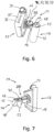
- FIG. 6 and 7 is in perspective an alternative embodiment of the one-handed operating device 11 to the Figures 1 to 4 shown.
- the main module 12 corresponds in structure to that shown in Figures 1 to 4 .
- the control lever 14 can be constructed according to the embodiment Figures 1 to 4 are equivalent to.
- a modified joint 16 is provided between the control lever 14 and the main module 12.
- This modified joint 16 may include a dial in place of the selector switch 38 to select individual operating modes.
- a display is provided in the modified joint 16 to display individual operating states or the like.
Landscapes
- Engineering & Computer Science (AREA)
- Physics & Mathematics (AREA)
- General Physics & Mathematics (AREA)
- Automation & Control Theory (AREA)
- Mining & Mineral Resources (AREA)
- Civil Engineering (AREA)
- General Engineering & Computer Science (AREA)
- Structural Engineering (AREA)
- Mechanical Control Devices (AREA)
Abstract
Description
- Die Erfindung betrifft eine Einhand-Bedieneinrichtung zur Steuerung einer Bewegung eines Objektes.
- Aus der
US 2020/0111635 A1 ist ein Einhand-Bediengerät bekannt. Dieses Einhand-Bediengerät umfasst ein Gehäuse mit einer oberen und unteren Stirnseite sowie einer vorderen und hinteren Stirnfläche als auch zwei einander gegenüberliegenden Seitenflächen. In der oberen Stirnseite ist ein Bedienelement in Form eines Not-Aus-Knopfes sowie ein Steuerhebel in Form eines Joysticks vorgesehen. An der vorderen Stirnseite ist ein weiteres Bedienelement, wie beispielsweise ein Taster, vorgesehen. An der hinteren Stirnseite können zwei weitere Bedienelemente vorgesehen sein, durch welche ein Taster zu betätigen ist. Dieses Einhand-Bediengerät ermöglicht zwar, dass der Benutzer das Gehäuse in einer Hand halten kann, jedoch ist die Betätigung des Joysticks mit dem Daumen der Hand, durch welche das Gehäuse gehalten wird, sehr schwierig. Darüber hinaus ist eine Betätigung des Not-Aus-Knopfes mit einem Zeigefinger sehr umständlich. Auch weist dieses Einhand-Bediengerät den Nachteil auf, dass nur eine geringe Anzahl von Achsen zur Ansteuerung eines Objektes ermöglicht ist. - Aus der
US 9 201 514 B1 - Aus der
FR 2 688 959 A1 - Aus der
DE 10 2013 110 681 A1 geht ein Steuerungsgehäuse für die Bedienung einer Maschine hervor. An einer Oberseite des Gehäuses sind Bedienelemente in Form eines Tasters oder eines Mini-Joysticks vorgesehen. - Aus der
DE 40 24 524 A1 ist ein Einhand-Bedienhebelelement mit einer Totmannschaltung zur Steuerung eines Rettungskorbes bekannt. An einer Oberseite des Gehäuses ist der Bedienungshebel schwenkbar aufgenommen. Zudem umfasst der Bedienhebel unterseitig in dem Steuergriff einen Riegel als Totmannschalter. - Der Erfindung liegt die Aufgabe zugrunde, eine Einhand-Bedieneinrichtung zur Steuerung einer Bewegung eines Objektes vorzuschlagen, welche eine einfache Einhand-Bedienung ermöglicht.
- Diese Aufgabe wird durch eine Einhand-Bedieneinrichtung gelöst, welche ein Hauptmodul mit einem Gehäuse umfasst, in welchem eine Steuerungseinrichtung vorgesehen ist, sowie einen Steuerhebel, der an dem Hauptmodul über ein Gelenk mit zumindest zwei Freiheitsgraden verbunden ist, wobei das Gelenk zur Aufnahme des Steuerhebels an einer äußeren Seitenfläche des Gehäuses vorgesehen ist und der Steuerhebel zumindest um eine Schwenkachse drehbar gelagert ist, wobei die Schwenkachse orthogonal oder in einem beliebigen Winkel zur Ebene der Seitenfläche des Gehäuses positionierbar ist und der Steuerhebel sich seitlich entlang der äußeren Seitenfläche in Richtung auf die vordere Stirnfläche des Gehäuses oder darüber hinaus erstreckt. Dies ermöglicht eine ergonomische Handhabung des Steuerhebels im Verhältnis zum Hauptmodul. Beispielsweise kann das Hauptmodul mit dem Steuerhebel durch den Bediener in einer für ihn günstigen Position getragen werden, so dass der Steuerhebel bei einem herabhängenden oder leicht angewinkelten Arm ergonomisch in günstiger Weise bedienbar ist. Durch die Zuordnung des Steuerhebels bezüglich deren Schwenkachse zu einer äußeren Seitenfläche des Hauptmoduls wird auch ermöglicht, dass der Steuerhebel zur Ansteuerung von einer Vielzahl von Achsen an dem zu bewegenden Objekt ausgebildet sein kann.
- Bevorzugt ist vorgesehen, dass das Hauptmodul zwischen der inneren und äußeren Seitenfläche eine Aussparung aufweist, die sich über die gesamte untere Stirnseite des Gehäuses erstreckt und wenigstens über die Hälfte der Höhe des Gehäuses zwischen der vorderen und hinteren Stirnfläche sich erstreckt. Diese Anordnung weist den Vorteil auf, dass der Benutzer das Hauptmodul beispielsweise in eine seitliche Tasche an einem Bekleidungsstück einstecken kann, wodurch eine einfache Fixierung ermöglicht ist. Die Einhand-Bedieneinrichtung kann mit dem Hauptmodul an einem Oberschenkel der Bedienperson anliegen und/oder sich abstützen. Darauffolgend kann der Benutzer durch die Betätigung des Steuerhebels eine Relativbewegung im Verhältnis zum Hauptmodul einleiten, um somit die Steuerung des zu bewegenden Objektes durchführen zu können.
- Alternativ kann vorgesehen sein, dass das Hauptmodul an seiner inneren Seitenfläche einen Halteclip aufweist. Dieser Halteclip kann die analoge Funktion wie die Aussparung in dem Hauptmodul aufweisen und eine einfache Befestigung an einem Bekleidungsstück der Bedienperson oder einem Gürtel oder Träger von der Bedienperson zu ermöglichen. Des Weiteren kann alternativ vorgesehen sein, dass das Hauptmodul in eine Tasche einsetzbar ist, welche beispielsweise an einem Gürtel oder einem Umhängegurt getragen wird, so dass die Tasche auf Höhe des Oberschenkels des Bedienpersonals positioniert ist oder befestigt werden kann. Zusätzlich kann ein Seil oder ein Riemen an dem Hauptmodul oder der Tasche für eine weitere Befestigung am Bein der Bedienperson vorgesehen sein.
- Gemäß einer weiteren bevorzugten Ausgestaltung der Erfindung ist vorgesehen, dass an der oberen Stirnseite des Gehäuses von dem Hauptmodul und/oder an einer äußeren Seitenfläche und/oder an einer vorderen Stirnfläche zumindest ein Bedienelement und/oder eine Anzeige vorgesehen ist. Beispielsweise kann an der oberen Stirnseite des Gehäuses des Hauptmoduls ein Not-Aus-Schalter vorgesehen sein. Des Weiteren kann an der oberen Stirnseite gut sichtbar eine Anzeige für einen Ladezustand eines Akkumulators vorgesehen sein, der in dem Hauptmodul zur Ansteuerung der Steuerungseinrichtung vorgesehen ist. An der oberen Stirnseite und/oder an einer vorderen Stirnfläche und/oder an einer äußeren Seitenfläche kann zumindest ein Bedienelement beispielsweise in Form eines Bedienknopfs, eines Tasters, eines Drehschalters und/oder Schieberiegels vorgesehen sein, um beispielsweise einen Betriebsmodus aus mehreren Betriebsmodi auszuwählen und/oder einzustellen.
- Der Steuerhebel weist bevorzugt an einem dem Gelenk gegenüberliegenden Ende zumindest ein Bedienelement auf, welches mit dem Daumen, dem Zeigefinger, dem Mittelfinger und/oder dem Ringfinger bedienbar ist. Beispielsweise kann vorgesehen sein, dass dem Daumen, dem Zeigefinger, dem Mittelfinger und/oder dem Ringfinger jeweils zumindest ein Bedienelement zugeordnet ist. Dadurch kann die Anzahl der Achsen zum Ansteuern an dem zu bewegenden Objekt erhöht werden. Auch kann die Sicherheit zur Bedienung der Einhand-Bedieneinrichtung erhöht werden, da die Bedienperson den Steuerhebel beispielsweise mit dem Daumenballen, dem Ringerfinger und dem kleinen Finger durch einen festen Griff halten kann und wahlweise das zumindest eine Bedienelement mit dem Daumen, Zeigefinger und/oder Mittelfinger einzeln aufeinanderfolgend und/oder wahlweise gleichzeitig betätigen kann.
- Der Steuerhebel weist gemäß einer bevorzugten Ausführungsform einen Griffabschnitt auf. Dieser Griffabschnitt ist zwischen der Anbindung des Steuerhebels über das Gelenk an dem Hauptmodul und einem gegenüberliegenden freien Ende vorgesehen. Der Griffabschnitt weist bevorzugt zumindest einen Sensor auf, der einen Griff von einer Hand der Bedienperson an dem Griffabschnitt erfasst und beim Erkennen eines Griffs die Steuerungseinrichtung freigibt und bei Nichterkennen eines Griffs die Steuerungseinrichtung sperrt. Dadurch ist ein Sicherheitsmerkmal für die Einhand-Bedieneinrichtung gegeben, da beim Lösen der Hand von dem Steuerhebel durch ein unbeabsichtigtes Betätigen des Steuerhebels eine Ansteuerung einer Bewegung des Objektes unterbunden ist. Ein solcher Sensor kann als ein Touch-Sensor oder ein Näherungsschalter ausgebildet sein.
- An dem Steuerhebel können die Bedienelemente in Form von Tasten, Kipphebel, Schieberiegel und/oder Kipphebel mit zumindest einem Freiheitsgrad und/oder Kipp-/Drehhebel mit zumindest einem Freiheitsgrad vorgesehen sein.
- Der Steuerhebel kann zwischen einer Anbindung an das Gelenk des Hauptmoduls und dem Griffabschnitt und/oder zwischen dem Griffabschnitt und einem freien Ende einen in Längsrichtung des Steuerhebels ausziehbaren Schiebeabschnitt aufweisen. Durch eine Zug- oder Druckbewegung kann der Schiebeabschnitt des Steuerhebels betätigbar sein. Diese flexible Anordnung ermöglicht des Weiteren eine Ansteuerung einer weiteren Achse an dem zu bewegenden Objekt.
- Die Ausgestaltung des Steuerhebels ermöglicht durch die Anzahl der Bedienelemente, dass sieben oder mehr Achsen an dem zu bewegenden Objekt ansteuerbar sind. Dadurch können auch komplexe Objekte lediglich mit der Einhand-Bedieneinrichtung ansteuerbar sein.
- Gemäß einer vorteilhaften Ausführungsform ist vorgesehen, dass der Steuerhebel an seinem freien Ende eine mechanische und/oder elektrische Schnittstelle zur lösbaren Anordnung von zumindest einem weiteren Bedienmodul mit zumindest einem Bedienelement aufweist. Auch kann das Hauptmodul zumindest eine mechanische und/oder elektrische Schnittstelle zur Anordnung eines weiteren Bedienelementes aufweisen. Dadurch ist die Einhand-Bedieneinrichtung individuell konfigurierbar und kann an die Anforderungen zur Ansteuerung des Objektes in einfacher Weise angepasst werden.
- Das Hauptmodul und der Steuerhebel sind bevorzugt durch eine lösbare Verbindung miteinander verbunden. Beispielsweise kann vorgesehen sein, dass der Steuerhebel mit dem Gelenk ausgebildet ist und das Gelenk an dem Hauptmodul, insbesondere der äußeren Seitenfläche des Gehäuses des Hauptmoduls, befestigbar ist. Alternativ kann vorgesehen sein, dass ein Teil des Gelenkes an dem Hauptmodul fixiert ist und der Steuerhebel lösbar an dem Gelenk angeordnet ist. Die Ausgestaltung des Steuerhebels, in welchem das Gelenk vorgesehen ist, kann des Weiteren ermöglichen, dass das Gelenk sowohl an der äußeren Stirnseite als auch der inneren Stirnseite des Hauptmoduls befestigbar ist, so dass die Einhand-Bedienung in einfacher Weise von einer Rechthand-Bedienung auf eine Linkshand-Bedienung umrüstbar ist.
- Des Weiteren kann bevorzugt vorgesehen sein, dass die Steuerung mit einer Datenbrille, vorzugsweise kabellos, kommuniziert. Hierbei kann es sich um eine sogenannte Augmented-Reality-Brille oder eine Mixed-Reality-Brille handeln. Dadurch kann der Benutzer, der entfernt vom Ort des Geschehens sich aufhält, eine Visualisierung über den Ort des Geschehens in der Datenbrille erfolgen.
- Nach einer bevorzugten Ausführungsform der Einhand-Bedieneinrichtung ist vorgesehen, dass in dem Hauptmodul und/oder in dem Steuerhebel zumindest ein Vibrationsaktor vorgesehen ist. Dadurch kann zumindest ein Systemzustand bzw. Betriebszustand des Objektes in taktiler Weise der Bedienperson signalisiert werden. Beispielsweise kann bei einem Kran ein Signal ausgegeben werden, dass das Heben einer Last nicht mehr möglich ist, da eine Überlastung des Kranes vorliegt. Auch kann signalisiert werden, dass beispielsweise ein Tragarm des Kranes vollständig ausgefahren ist oder dass Stützen des Kranfahrzeuges aus- oder eingefahren sind. Weitere Betriebszustände können ebenfalls kommuniziert bzw. signalisiert werden. Durch ein solches taktile Feedback kann die Sicherheit für die Bedienung des Objektes durch die Bedienperson erhöht sein.
- Bevorzugt ist vorgesehen, dass der zumindest eine Vibrationsaktor bei Erreichen eines vorbestimmten Betriebszustandes des Objektes aktivierbar ist. Der vorbestimmte Betriebszustand kann in der Steuerung definiert und hinterlegt werden. Dies kann das Erreichen eines Zwischenpunktes oder Endpunktes nach einer Verfahrbewegung einer Komponente des Objektes oder ein Auftreten eines Widerstandes bei der Ansteuerung einer Bewegung des Objektes oder ein Erreichen eines Zustandes des Objektes sein.
- Gemäß einer vorteilhaften Ausführungsform ist vorgesehen, dass beim Erreichen des einen vorbestimmten Betriebszustandes des Objektes der Vibrationsaktor in dem Hauptmodul und der Vibrationsaktor in dem Steuerhebel im Wechsel aufeinanderfolgend aktivierbar sind. Dadurch kann die Bedienperson beispielsweise auch dann ein taktiles Feedback erhalten, sofern die Hand nicht am Steuerhebel ist oder sofern die Hand am Steuerhebel ist und das Bekleidungsstück der Bedienperson eine zu hohe Dämpfung für das Signal des Vibrationsaktor aufweist.
- Eine weitere vorteilhafte Ausgestaltung der Einhand-Bedieneinrichtung sieht vor, dass dem Vibrationsaktor in dem Hauptmodul und dem Vibrationsaktor in dem Steuerhebel zwei voneinander abweichende Betriebszustände zugeordnet sind und die Vibrationsaktoren jeweils voneinander abweichende Signale ausgeben. Dadurch ist für die Bedienperson eine einfache Zuordnung bezüglich des jeweiligen Betriebszustandes des Objektes anhand des taktilen Feedbacks im Hauptmodul und/oder im Steuerhebel möglich. Bei einem Fahrzeug mit einem Kran können beispielsweise über den Steuerhebel Betriebszustände des Kranes und über das Hauptmodul Betriebszustände des Fahrzeuges kommuniziert werden. Dies kann auch vertauscht sein.
- Die Erfindung sowie weitere vorteilhafte Ausführungsformen und Weiterbildungen derselben werden im Folgenden anhand der in den Zeichnungen dargestellten Beispiele näher beschrieben und erläutert. Die der Beschreibung und den Zeichnungen zu entnehmenden Merkmale können einzeln für sich oder zu mehreren in beliebiger Kombination erfindungsgemäß angewandt werden. Es zeigen:
- Figur 1
- eine schematische Seitenansicht einer Einhand-Bedieneinrichtung,
- Figur 2
- eine schematische Ansicht von oben auf die EinhandBedieneinrichtung gemäß
Figur 1 , - Figur 3
- eine perspektivische Ansicht eines Hauptmoduls der Einhand-Bedieneinrichtung,
- Figur 4
- eine schematische Seitenansicht der Einhand-Bedieneinrichtung in einer Benutzungsposition,
- Figur 5
- eine schematische Darstellung eines mit der Einhand-Bedieneinrichtung zu bewegenden Objektes,
- Figur 6
- eine perspektivische Ansicht einer alternativen Ausführungsform der Einhand-Bedieneinrichtung gemäß
Figur 1 , und - Figur 7
- eine weitere perspektivische Ansicht der Einhand-Bedieneinrichtung gemäß
Figur 6 . - In
Figur 1 ist eine schematische Seitenansicht einer Einhand-Bedieneinrichtung 11 dargestellt. DieFigur 2 zeigt eine Ansicht von oben auf die Einhand-Bedieneinrichtung 11 gemäßFigur 1 . Eine solche Einhand-Bedieneinrichtung 11 dient zur Steuerung von einer Bewegung eines Objektes 71 (Figur 5 ). Ein solches Objekt 71 kann beispielsweise ein Kran zum Heben und Senken von Lasten, insbesondere ein Faltkran oder komplexe Kräne mit Anbauteilen, sein. Auch können Robotersysteme oder Drohnen, insbesondere zum Lastentransport, damit ansteuerbar sein. Diese Aufzählung der Anwendungsfälle ist nicht abschließend. - Die Einhand-Bedieneinrichtung 11 umfasst ein Hauptmodul 12 sowie einen Steuerhebel 14. Das Hauptmodul 12 und der Steuerhebel 14 sind durch ein Gelenk 16 mit wenigstens zwei Freiheitsgraden miteinander verbunden. Vorzugsweise ist eine lösbare Verbindung zwischen dem Steuerhebel 14 und dem Gelenk 16 und/oder zwischen dem Gelenk 16 und dem Hauptmodul 12 vorgesehen.
- Das Hauptmodul 12 umfasst ein Gehäuse 18 mit einer oberen und unteren Stirnseite 19, 21 sowie eine vordere und hintere Stirnfläche 22, 23.
- Des Weiteren umfasst das Gehäuse 18 eine innere Seitenfläche 24 und eine äußere Seitenfläche 26. Das Gehäuse 18 ist bevorzugt als ein geschlossenes Gehäuse ausgebildet. Die obere und/oder untere Stirnseite 19, 21 und/oder die vordere und/oder hintere Stirnfläche 22, 23 können einzeln oder in einer beliebigen Anzahl auch gerundet ausgebildet sein. Auch kann eine davon abweichende Anzahl von Stirnseiten und/oder Stirnflächen vorgesehen sein. Die obere Stirnseite 19 ist insbesondere als eine Stirnfläche oder gestufte Fläche ausgebildet, in welcher Bedienelemente positioniert sind.
- In dem Gehäuse 18 des Hauptmoduls 12 ist bevorzugt eine Steuerungseinrichtung 28 zur Ausgabe und/oder Empfang von Signalen vorgesehen. Diese Steuerungseinrichtung 28 kann kontaktlos mit dem zu bewegenden Objekt 71 zur Ausgabe und/oder zum Empfang von Daten und Signalen kontaktlos kommunizieren. Des Weiteren ist in dem Gehäuse 18 ein Akkumulator 29 vorgesehen. Eine Schnittstelle zum Aufladen des Ackumulators 29 ist der Einfachheit halber nicht dargestellt. Alternativ kann der Akkumulator 29 auch entnehmbar an dem Gehäuse 18 vorgesehen sein, um einer Ladestation zuzuführen.
- An einer äußeren Seitenfläche 26 des Gehäuses 18 kann ein Fenster 31 vorgesehen sein, in welchem eine nicht näher dargestellte Antenne der Steuerungseinrichtung 28 zugeordnet ist, um eine verbesserte Übertragung von Signalen zu ermöglichen. Des Weiteren kann an einer äußeren Seitenfläche 26 des Gehäuses 18 ein Beleuchtungsfeld 32 vorgesehen sein, so dass bei Dunkelheit eine Sichthilfe gegeben ist.
- Sowohl an dem Hauptmodul 12 als auch an dem Steuerhebel 14 können ein oder mehrere Bedienelemente vorgesehen sein. Diese Bedienelemente werden nachfolgend im Einzelnen beschrieben. Einzelne Bedienelemente insbesondere an dem Steuerhebel 14 können frei programmierbar sein, so dass dem Benutzer oder der Bedienperson eine persönliche Konfiguration ermöglicht ist. Durch die Steuerungseinrichtung 28 wird diese personifizierte Konfiguration abgespeichert.
- An dem Hauptmodul 12 ist als Bedienelement eine Not-Aus-Taste 34 vorgesehen. Bevorzugt ist diese Not-Aus-Taste 34 an der oberen Stirnseite 19, insbesondere im vorderen Bereich der oberen Stirnseite 19, vorgesehen. Dies ermöglicht, dass nach dem Lösen eines Griffs von dem Steuerhebel 14 mit dem Daumen eine schnelle Betätigung der Not-Aus-Taste 34 erfolgen kann. Des Weiteren kann an der oberen Stirnseite 19 ein Anzeigefeld 35 zur Darstellung des Ladezustands der Akkumulatoren 29 vorgesehen sein. Beispielsweise an der oberen Stirnseite 19 auch ein Bedienelement in Form einer Ein-/Aus-Taste 36 vorgesehen sein. Diese ist vorteilhafterweise beleuchtet und zeigt den Betriebszustand an. Alternativ kann diese Ein- und Aus-Taste 36 oder An- oder Ausschalter 36 auch an weiteren Seitenflächen des Gehäuses 18 vorgesehen sein.
- Bei diesem Ausführungsbeispiel des Hauptmoduls 12 ist beispielsweise die vordere und hintere Stirnfläche, sowie die untere Stirnseite 21 frei von Bedienelementen. Wahlweise kann auch an diesen Stirnflächen oder Stirnseiten zumindest ein Bedienelement vorgesehen sein.
- An der äußeren Seitenfläche 26 des Hauptmoduls 12 ist bevorzugt ein Wählschalter 38, insbesondere in Form eines Drehknopfes, vorgesehen. Durch diesen Wählschalter 38 können verschiedene Betriebsmodi ausgewählt werden. Auch ist möglich, dass durch den Wahlschalter 38 nur einzelne Achsen an einem zu bewegenden Objekt 71 zur Ansteuerung ausgewählt und freigegeben werden können. Dies wird nachfolgend noch anhand des Ausführungsbeispiels gemäß
Figur 5 näher beschrieben. - Der Steuerhebel 14 ist des Weiteren der äußeren Seitenfläche 26 des Gehäuses 18 von dem Hauptmodul 12 zugeordnet. Dieser Steuerhebel 14 ist um eine Achse 41 an dem Hauptmodul 12 oder an dem Gelenk 16 angebunden. In einer Ausgangsposition des Steuerhebels 14 steht die Achse 41 vorzugsweise rechtwinklig zur Ebene der äußeren Seitenfläche 26. Des Weiteren kann der Steuerhebel 41 in der Ausgangsposition so ausgerichtet sein, dass beispielsweise ein Griffabschnitt 42, der zwischen der Achse 41 und einem freien Ende 44 des Steuerhebels 14 positioniert ist, in einer horizontalen Ausrichtung oder nahezu horizontalen Ausrichtung ausgerichtet ist. Der Griffabschnitt 42 erstreckt sich ausgehend von dem Gelenk 41 in Richtung auf die vordere Stirnfläche 22 und kann sich dieser gegenüber nach außen erstrecken. Die Winkelposition des Griffabschnitts 42 des Steuerhebels 14 kann durch die Bedienperson im Verhältnis zum Hauptmodul 12 frei wählbar sein. Dadurch kann eine ergonomisch günstige Ausrichtung des Steuerhebels 14 zum Hauptmodul 12 oder Bedienperson gegeben sein.
- Am vorderen Ende des Steuerhebels 14 können mehrere Bedienelemente vorgesehen sein. Beispielsweise können zwei Taster 46, 47 bzw. Drückknöpfe gegeben sein. Der eine Taster 46 kann für das Einschalten einer Funktion und der zweite Taster 47 für das Ausschalten einer Funktion sein. Benachbart zu den Tastern 46, 47 kann ein oder mehrere weitere Taster 48 positioniert werden. Diese Taster 46, 47, 48 können alle bevorzugt mit dem Daumen ansteuerbar sein.
- Dem freien Ende 44 des Steuerhebels 14 kann des Weiteren ein mit dem Daumen betätigbarer Kipphebel oder Dreh-/Kipphebel 49 zugeordnet sein. Dieser Kipphebel oder Dreh-/Kipphebel 49 kann die Funktion eines Joysticks umfassen. Die Ausgestaltung eines Kipphebels oder Dreh-/ Kipphebels 49 ermöglicht, dass zwei oder auch drei Achsen gemeinsam mit diesem einen Bedienelement betätigbar sein können.
- Des Weiteren kann an dem Steuerhebel 14 im Bedienbereich des Zeigefingers ein Taster oder Druckknopf 51 und/oder ein Wipphebel 52 vorgesehen sein. Beispielsweise können diese beiden Bedienelemente 51, 52 auch miteinander kombiniert werden, so dass nach dem Betätigen des Wipphebels 52 die betätigte Position des Wipphebels 52 durch den Druckknopf 51 arretiert bleibt. Durch weiteres Betätigen des Wipphebels 52 wird die Arretierung gelöst.
- An dem freien Ende oder nahe dem freien Ende 44 des Steuerhebels 14 ist zumindest eine mechanische und/oder elektrische Schnittstelle 55 vorgesehen. An diese Schnittstelle 55 ist ein Bedienmodul 57 anschließbar. Dieses Bedienmodul 57 kann ein oder mehrere Bedienelemente umfassen. Im Ausführungsbeispiel ist eine Taste 58 und ein Schieberiegel 59 vorgesehen. Dies ist nur beispielhaft.
- Der Steuerhebel 14 weist vorteilhafterweise in dem Griffabschnitt 42 zumindest einen Sensor 43 auf. Dieser Sensor 43 erfasst, ob die Bedienperson an dem Steuerhebel 14 angreift oder nicht. Sobald der Sensor 43 einen Griff durch die Bedienperson feststellt, wird die Steuerungseinrichtung 28 zum Empfang und/oder zur Ausgabe von Signalen freigegeben und beim Lösen des Griffs wird die Steuerungseinrichtung 28 stillgesetzt.
- Der Steuerhebel 14 kann bevorzugt einen Schiebeabschnitt 61 aufweisen. Durch diesen Schiebeabschnitt 61 ist eine zusätzliche Achse ansteuerbar. Beispielsweise kann der Griffabschnitt 42 gegenüber einem Anschluss an die Achse 41 oder das Gelenk 16 aus- und einfahrbar sein.
- Zur lösbaren Befestigung des Steuerhebels 14, beispielsweise an dem Gelenk 16, kann ein lösbares Verschlusselement 63, wie beispielsweise eine Schraube, insbesondere mit einem Rändelkopf, vorgesehen sein.
- In
Figur 3 ist eine perspektivische Ansicht des Hauptmoduls 12 dargestellt. Der Steuerhebel 14 ist abgenommen. Aus der Ansicht ist zu ersehen, dass das Gehäuse 18 eine Aussparung 65 aufweisen kann. Diese Aussparung 65 ist als ein Schlitz ausgebildet, der sich von der unteren Seitenfläche 21 in Richtung auf die obere Fläche 19 erstreckt. Auch erstreckt sich die Aussparung 65 von der vorderen Seitenfläche 22 zur hinteren Seitenfläche 23. Diese Aussparung 65 dient als eine einfache Befestigungsmöglichkeit des Hauptmoduls 12 an einem Bekleidungsstück der Bedienperson. Dies ist beispielsweise inFigur 4 dargestellt. Ein Gehäuseteil mit der inneren Seitenfläche 24 kann in eine Tasche eines Bekleidungsstücks der Bedienperson eingesteckt werden. Die äußere Seitenfläche 26 mit dem daran angeordneten Steuerhebel 14 ist für die Einhand-Bedienung frei zugänglich. Die Positionierung der Einhand-Bedieneinrichtung 11 ist beispielsweise in einer Hosentasche oder in einer Beintasche möglich oder an einem Gürtel oder einem Trageriemen, so dass bei einem herabhängenden Arm in ergonomisch günstiger Weise eine Bedienung des Steuerhebels 14 ermöglicht ist. Dieser Steuerhebel 14 kann relativ zum Hauptmodul 12 um eine X-Achse gemäßFigur 1 auf- und abbewegbar sein. Der Steuerhebel 14 kann in Y-Richtung ausziehbar sein. Des Weiteren kann der Steuerhebel 14 mit einer Taumelbewegung um die orthogonale Achse 41 zur Ebene der äußeren Seitenfläche 26 ansteuerbar sein. Zusätzlich und/oder alternativ können die vorbenannten Bedienelemente wahlweise betätigbar sein. - Diese Einhand-Bedieneinrichtung 11 ermöglicht die Ansteuerung von sieben oder mehr Achsen an einem zu bewegenden Objekt 71. Durch den Steuerhebel 14 erfolgt ein direktes Ansteuern der einzelnen Achsen des Objektes 71. Diese Ansteuerung durch den Steuerhebel 14 erfolgt taktil.
- Vorteilhafterweise ist vorgesehen, dass die Einhand-Bedieneinrichtung 11 zumindest einen Vibrationsaktor 67 aufweist. Beispielsweise ist ein Vibrationsaktor 67 im Hauptmodul 12 vorgesehen. Dieser Vibrationsaktor 67 kann einer inneren Seitenfläche 24 im Hauptmodul 12 zugeordnet sein. Des Weiteren kann ein Vibrationsaktor 67 im Steuerhebel 14 vorgesehen sein. Durch den oder die Vibrationsaktoren 67 können einzeln oder gemeinsam ein Betriebszustand des Objektes 71 in taktiler Weise realisiert werden. Auch kann jedem Vibrationsaktor 67 ein vorbestimmter Betriebszustand des Objektes 71 zugeordnet sein. Dadurch kann die Bedienperson über diesen zumindest einen Vibrationsaktor 67 zumindest eine zusätzliche Information erhalten. Andere Beteiligte, die benachbart zu der Bedienperson stehen oder sich aufhalten, werden nicht verunsichert, wie dies durch etwaige akustische Signale der Fall wäre.
- In
Figur 5 ist beispielhaft ein zu bewegendes Objekt 71 dargestellt. Hierbei handelt es sich um ein Kranfahrzeug mit einem faltbaren Kransystem. Beispielsweise können damit Lasten 72 an einem bestimmen Ort 74 abgelegt werden, bei welchem beispielsweise verschiedentliche Höhen zu überwinden sind. Nachdem sich das Kranfahrzeug beziehungsweise Objekt 71 an dem Ort des Geschehens befindet, muss das Kranfahrzeug gesichert werden. Beispielsweise wird der Wählschalter 38 auf die Position 76 übergeführt. Dadurch kann der Betriebsmodus ausgewählt werden, dass durch den Steuerhebel 14 nur das Ausfahren und Positionieren der Stützen 72, 86 angesteuert wird. Darauffolgend kann der Wählschalter 38 in die Position 77 übergeführt werden, in der nur ein Ausfahren von faltbaren Kranarmen 81, 82, 83 ansteuerbar ist. Weitere Achsen an dem Objekt 71 können dabei nicht angesteuert werden. Darauffolgend kann der Wählschalter 38 in die Position 78 übergeführt werden, um beispielsweise die Last 72 von dem Ort des Geschehens an einen Bereitstellungsort überzuführen. In diesem Fall können über den Steuerhebel 14 die Kranarme 81, 82, 83 als auch das Aus- und Einfahren einer Seilwinde angesteuert werden. Beispielsweise kann mit einem Bedienelement eine erste Achse des Kranarmes 81 für eine Auf- und Abbewegung gegenüber dem Objekt 71 beziehungsweise Kranfahrzeug angesteuert werden. Mit einem weiteren Bedienelement kann eine Drehbewegung des ersten Kranarmes 81 als zweite Achse ansteuerbar sein. Mit einem weiteren Bedienelement kann eine dritte Achse des zweiten Kranarmes 82 angesteuert werden, indem dieser aus- und einfahrbar bzw. teleskopierbar ist. Mit einem weiteren Bedienelement kann die Auf- und Abbewegung des zweiten Kranarmes 82 als vierte Achse angesteuert werden. Darüber hinaus kann mit einem weiteren Bedienelement der dritte Kranarm 83 angesteuert werden. Die Ansteuerung einer Auf- und Abbewegung des dritten Kranarmes 83 entspricht einer fünften Achse und die Ansteuerung einer ausfahrbaren Länge entspricht einer sechsten Achse. Die Ansteuerung des Seilantriebes zum Heben und Senken der Last 72 mit einem weiteren Bedienelement entspricht einer siebten Achse. - Der Wählschalter 38 kann in eine weitere Position 79 übergeführt werden. In diesem Betriebsmodus können individuelle Konfigurationen abgespeichert und aufgerufen werden, die an spezifische Anforderungen der Objekte 71 angepasst sein können.
- In den
Figuren 6 und 7 ist perspektivisch eine alternative Ausführungsform der Einhand-Bedieneinrichtung 11 zu denFiguren 1 bis 4 dargestellt. Das Hauptmodul 12 entspricht im Aufbau dem gemäß denFiguren 1 bis 4 . Der Steuerhebel 14 kann im Aufbau der Ausführungsform gemäß denFiguren 1 bis 4 entsprechen. Zwischen dem Steuerhebel 14 und dem Hauptmodul 12 ist ein modifiziertes Gelenk 16 vorgesehen. Dieses modifizierte Gelenk 16 kann eine Wählscheibe anstelle des Wählschalters 38 umfassen, um einzelne Betriebsmodi auszuwählen. Alternativ kann auch vorgesehen sein, dass in dem modifizierten Gelenk 16 ein Display vorgesehen ist, um einzelne Betriebszustände oder dergleichen anzuzeigen.
Claims (15)
- Einhand-Bedieneinrichtung zur Steuerung eines Objektes (71),- mit einem Hauptmodul (12),- mit einem Steuerhebel (14), welcher mit dem Hauptmodul (12) mit einem Gelenk (16) mit zumindest zwei Freiheitsgraden verbunden ist,- mit einer in dem Hauptmodul (12) vorgesehenen Steuerungseinrichtung (28), welche zum Verarbeiten von Steuersignalen des Steuerhebels (14) und/oder Bedienelementen an dem Hauptmodul (12) vorgesehen ist und welche zum Empfang und/oder Ausgabe von Signalen an und/oder von dem Objekt (71) ausgebildet ist,- wobei das Hauptmodul (12) ein Gehäuse (18) umfasst, welches eine obere und/oder untere Stirnseite (19, 21) und/oder eine vordere und/oder hintere Stirnfläche (22, 23) umfasst sowie eine innere und äußere Seitenfläche (24, 26),
dadurch gekennzeichnet, dass- der Steuerhebel (14) durch das Gelenk (16) an der äußeren Seitenfläche (26) des Gehäuses (18) vorgesehen ist und der Steuerhebel (14) zumindest um eine Schwenkachse (41) drehbar ist, welche orthogonal zu einer Ebene der äußeren Seitenfläche (26) oder in einem Winkel zu der Ebene der äußeren Seitenfläche (26) positionierbar ist, und- der Steuerhebel (14) sich seitlich entlang der äußeren Seitenfläche (26) des Gehäuses (18) in Richtung auf die vordere Stirnfläche (22) des Gehäuses (18) oder darüber hinaus erstreckt. - Einhand-Bedieneinrichtung nach Anspruch 1, dadurch gekennzeichnet, dass das Hauptmodul (12) zwischen der inneren und äußeren Seitenfläche (24, 26) eine Aussparung (65) aufweist, die sich über die gesamte untere Stirnfläche (21) erstreckt und wenigstens über die Hälfte der Höhe der vorderen und hinteren Stirnfläche (22, 23) sich erstreckt.
- Einhand-Bedieneinrichtung nach Anspruch 1, dadurch gekennzeichnet, dass das Hauptmodul (12) an seiner inneren Seitenfläche (24) ein Befestigungselement, insbesondere Halteclip, aufweist.
- Einhand-Bedieneinrichtung nach einem der vorhergehenden Ansprüche, dadurch gekennzeichnet, dass das Hauptmodul (12) an der oberen Stirnseite (19), der vorderen Stirnfläche (22), der hinteren Stirnfläche (23) und/oder der äußeren Seitenfläche (26) zumindest ein Bedienelement und/oder ein Anzeigenfeld (35) aufweist.
- Einhand-Bedieneinrichtung nach einem der vorhergehenden Ansprüche, dadurch gekennzeichnet, dass der Steuerhebel (14) an einem der Schwenkachse (41) des Steuerhebels (14) gegenüberliegenden Ende zumindest ein Bedienelement aufweist, welches mit einem Daumen, einem Zeigefinger und/oder einem Mittelfinger bedienbar ist.
- Einhand-Bedieneinrichtung nach einem der vorhergehenden Ansprüche, dadurch gekennzeichnet, dass der Schwenkhebel (14) einen Griffabschnitt (42) aufweist, der zumindest einen Sensor (43) umfasst, durch welchen ein Griff von einer Hand einer Bedienperson an dem Griffabschnitt (42) erfassbar ist und beim Erfassen des Griffs an dem Griffabschnitt (42) durch den Sensor (43) die Steuerungseinrichtung (38) freigibt oder beim Lösen des Griffs von dem Griffabschnitt (42) die Steuerungseinrichtung (38) sperrt.
- Einhand-Bedieneinrichtung nach einem der vorhergehenden Ansprüche, dadurch gekennzeichnet, dass der Steuerhebel (14) Bedienelemente in Form von Tasten (46, 47, 48), Wipphebel (52), Schieberiegel (59), Druckknöpfe (51), Kipphebel (49) mit zumindest einem Freiheitsgrad und/oder Kipp-/Drehhebel mit zumindest einem Freiheitsgrad aufweist.
- Einhand-Bedieneinrichtung nach einem der vorhergehenden Ansprüche, dadurch gekennzeichnet, dass der Steuerhebel (14) zwischen dem Gelenk (16) und dem Griffabschnitt (42) und/oder zwischen dem Griffabschnitt (42) und dem freien Ende (44) des Steuerhebels (14) ein in Längsrichtung des Steuerhebels (14) ausziehbaren Schiebeabschnitt (61) aufweist.
- Einhand-Bedieneinrichtung nach einem der vorhergehenden Ansprüche, dadurch gekennzeichnet, dass der Steuerhebel (14) zumindest eine Anzahl von Bedienelementen aufweist, durch welche sieben oder mehr Achsen an dem Objekt (71) ansteuerbar sind.
- Einhand-Bedieneinrichtung nach einem der vorhergehenden Ansprüche, dadurch gekennzeichnet, dass der Steuerhebel (14) an seinem freien Ende (44) zumindest eine mechanische und/oder elektrische Schnittstelle (55) zur lösbaren Anordnung von zumindest einem weiteren Bedienmodul (57) mit zumindest einem Bedienelement aufweist.
- Einhand-Bedieneinrichtung nach einem der vorhergehenden Ansprüche, dadurch gekennzeichnet, dass der Steuerhebel (14) lösbar an dem Gelenk (16) oder der Schwenkachse (41) an dem Hauptmodul (12) befestigt ist.
- Einhand-Bedieneinrichtung nach einem der vorhergehenden Ansprüche, dadurch gekennzeichnet, dass im Hauptmodul (12) und/ oder im Steuerhebel (14) zumindest ein Vibrationsaktor (67) vorgesehen ist.
- Einhand-Bedieneinrichtung nach Anspruch 12, dadurch gekennzeichnet, dass der zumindest eine Vibrationsaktor (67) beim Erreichen eines vorbestimmten Betriebszustandes des Objektes (71) aktivierbar ist.
- Einhand-Bedieneinrichtung nach Anspruch 13, dadurch gekennzeichnet, dass beim Erreichen des einen vorbestimmten Betriebszustandes des Objektes (71) der Vibrationsaktor (67) im Hauptmodul (12) und der Vibrationsaktor (67) im Steuerhebel (14) im Wechsel aufeinanderfolgend aktivierbar sind.
- Einhand-Bedieneinrichtung nach Anspruch 13, dadurch gekennzeichnet, dass der Vibrationsaktor (67) im Hauptmodul (12) und der Vibrationsaktor (67) im Steuerhebel (14) zwei voneinander abweichende Signale ausgeben, die jeweils dem einen Betriebszustand des Objektes (71) zugeordnet sind.
Applications Claiming Priority (1)
| Application Number | Priority Date | Filing Date | Title |
|---|---|---|---|
| DE102022115160.3A DE102022115160A1 (de) | 2022-06-17 | 2022-06-17 | Einhand-Bedieneinrichtung |
Publications (1)
| Publication Number | Publication Date |
|---|---|
| EP4293471A1 true EP4293471A1 (de) | 2023-12-20 |
Family
ID=86387228
Family Applications (1)
| Application Number | Title | Priority Date | Filing Date |
|---|---|---|---|
| EP23173909.5A Pending EP4293471A1 (de) | 2022-06-17 | 2023-05-17 | Einhand-bedieneinrichtung |
Country Status (2)
| Country | Link |
|---|---|
| EP (1) | EP4293471A1 (de) |
| DE (1) | DE102022115160A1 (de) |
Citations (12)
| Publication number | Priority date | Publication date | Assignee | Title |
|---|---|---|---|---|
| DE4024524A1 (de) | 1990-08-02 | 1992-02-06 | Iveco Magirus | Einhand-bedienhebelelement mit totmannschaltung zur steuerung eines rettungskorbes, insbesondere eines rettungseinsatzfahrzeuges |
| FR2688959A1 (fr) | 1992-01-24 | 1993-09-24 | Fusilier Jean Marie | Dispositif manipulateur unitaire pour la telecommande sans fil d'une unite fonctionnelle. |
| EP1568651A2 (de) * | 2004-02-12 | 2005-08-31 | Still Gmbh | Bedienanordnung einer mobilen Arbeitsmaschine |
| EP1353257B1 (de) * | 2002-04-12 | 2007-09-12 | Fernsteuergeräte Kurt Oelsch GmbH | Steuergriff mit Betätigungseinheiten |
| DE102013110681A1 (de) | 2013-09-26 | 2015-03-26 | Terex Mhps Gmbh | Steuerschalter für eine Bedienung einer Maschine, insbesondere eine drahtlose, tragbare und handbetätigbare Fernbedienung für einen Kran |
| US9201514B1 (en) | 2008-10-16 | 2015-12-01 | Danfoss Power Solutions Inc. | Joystick grip with integrated display |
| US20170233983A1 (en) * | 2016-02-16 | 2017-08-17 | Caterpillar Inc. | Control device for an implement system |
| EP2878858B1 (de) * | 2013-11-29 | 2019-03-27 | CLAAS Selbstfahrende Erntemaschinen GmbH | Bedienkonzept zum Fahren eines Selbstfahrers |
| US20200111635A1 (en) | 2018-10-05 | 2020-04-09 | Measurement Systems, Inc. | Single hand controller |
| WO2021121900A1 (de) * | 2019-12-17 | 2021-06-24 | Thomas Haug | Steuerungsvorrichtung |
| EP3211505B1 (de) * | 2016-02-25 | 2021-09-22 | Makersan Makina Otomotiv Sanayi Ticaret Anonim Sirketi | Mehrachs steuerungshebel mit dichtfunktion |
| US20210331307A1 (en) * | 2019-01-04 | 2021-10-28 | Industry-University Cooperation Foundation Hanyang University Erica Campus | Controller, adjustment device, and adjustment system |
-
2022
- 2022-06-17 DE DE102022115160.3A patent/DE102022115160A1/de active Pending
-
2023
- 2023-05-17 EP EP23173909.5A patent/EP4293471A1/de active Pending
Patent Citations (12)
| Publication number | Priority date | Publication date | Assignee | Title |
|---|---|---|---|---|
| DE4024524A1 (de) | 1990-08-02 | 1992-02-06 | Iveco Magirus | Einhand-bedienhebelelement mit totmannschaltung zur steuerung eines rettungskorbes, insbesondere eines rettungseinsatzfahrzeuges |
| FR2688959A1 (fr) | 1992-01-24 | 1993-09-24 | Fusilier Jean Marie | Dispositif manipulateur unitaire pour la telecommande sans fil d'une unite fonctionnelle. |
| EP1353257B1 (de) * | 2002-04-12 | 2007-09-12 | Fernsteuergeräte Kurt Oelsch GmbH | Steuergriff mit Betätigungseinheiten |
| EP1568651A2 (de) * | 2004-02-12 | 2005-08-31 | Still Gmbh | Bedienanordnung einer mobilen Arbeitsmaschine |
| US9201514B1 (en) | 2008-10-16 | 2015-12-01 | Danfoss Power Solutions Inc. | Joystick grip with integrated display |
| DE102013110681A1 (de) | 2013-09-26 | 2015-03-26 | Terex Mhps Gmbh | Steuerschalter für eine Bedienung einer Maschine, insbesondere eine drahtlose, tragbare und handbetätigbare Fernbedienung für einen Kran |
| EP2878858B1 (de) * | 2013-11-29 | 2019-03-27 | CLAAS Selbstfahrende Erntemaschinen GmbH | Bedienkonzept zum Fahren eines Selbstfahrers |
| US20170233983A1 (en) * | 2016-02-16 | 2017-08-17 | Caterpillar Inc. | Control device for an implement system |
| EP3211505B1 (de) * | 2016-02-25 | 2021-09-22 | Makersan Makina Otomotiv Sanayi Ticaret Anonim Sirketi | Mehrachs steuerungshebel mit dichtfunktion |
| US20200111635A1 (en) | 2018-10-05 | 2020-04-09 | Measurement Systems, Inc. | Single hand controller |
| US20210331307A1 (en) * | 2019-01-04 | 2021-10-28 | Industry-University Cooperation Foundation Hanyang University Erica Campus | Controller, adjustment device, and adjustment system |
| WO2021121900A1 (de) * | 2019-12-17 | 2021-06-24 | Thomas Haug | Steuerungsvorrichtung |
Also Published As
| Publication number | Publication date |
|---|---|
| DE102022115160A1 (de) | 2023-12-28 |
Similar Documents
| Publication | Publication Date | Title |
|---|---|---|
| EP0840910B1 (de) | Programmiergerät | |
| EP3115863B1 (de) | Steuerelement | |
| DE102014109500B4 (de) | Verbindungsvorrichtung | |
| DE102010054877A1 (de) | Kleinkind-Transportvorrichtung mit einem Freigabe-Aktuator, der eine Sicherheits-Verriegelungseinrichtung aufweist | |
| DE202012003790U1 (de) | Straßenfertiger mit verstellbarem Bedienpult | |
| DE202021104894U1 (de) | Fahrzeugtischvorrichtung | |
| EP0027238A2 (de) | Knarre mit am Griffstiel angelenktem Arbeitskopf | |
| DE4024524A1 (de) | Einhand-bedienhebelelement mit totmannschaltung zur steuerung eines rettungskorbes, insbesondere eines rettungseinsatzfahrzeuges | |
| DE7728591U1 (de) | Sprecheinrichtung mit verriegelung | |
| EP2138985A2 (de) | Fernsteuerungssystem eines Arbeitsgerätes | |
| DE102015209024B4 (de) | Bildschirmlesegerät | |
| DE4206515C1 (de) | ||
| DE102022115160A1 (de) | Einhand-Bedieneinrichtung | |
| WO2008064380A1 (de) | Tragbare bedien- und beobachtungsvorrichtung für eine industrielle steuerungseinrichtung | |
| EP4147118B1 (de) | Eingabevorrichtung | |
| EP2491874A1 (de) | Chirurgisches Instrument mit verbesserter Handhabbarkeit | |
| DE60011786T2 (de) | Betätigungsvorrichtung für Arbeitsfahrzeuge | |
| EP1682397A1 (de) | Vorrichtung zum bedienen eines fahrzeugs | |
| DE10013054A1 (de) | Bedieneinheit für Multi-Media-Komponenten in einem Kraftfahrzeug | |
| WO2002082954A1 (de) | Elektromotorischer möbelantrieb zum verstellen von teilen eines möbels relativ zueinander | |
| DE602004013191T2 (de) | Elektrowerkzeug mit doppelt steuerbarem schalter | |
| DE8806214U1 (de) | Gehäuse für ein Handbediengerät | |
| DE102018110137B4 (de) | Innenraumkomponente für ein Kraftfahrzeug | |
| DE19643201B4 (de) | Fernbedienungsgeber | |
| DE19630971C1 (de) | Tragbares Einhand-Bedienungsgerät |
Legal Events
| Date | Code | Title | Description |
|---|---|---|---|
| PUAI | Public reference made under article 153(3) epc to a published international application that has entered the european phase |
Free format text: ORIGINAL CODE: 0009012 |
|
| STAA | Information on the status of an ep patent application or granted ep patent |
Free format text: STATUS: THE APPLICATION HAS BEEN PUBLISHED |
|
| AK | Designated contracting states |
Kind code of ref document: A1 Designated state(s): AL AT BE BG CH CY CZ DE DK EE ES FI FR GB GR HR HU IE IS IT LI LT LU LV MC ME MK MT NL NO PL PT RO RS SE SI SK SM TR |
|
| STAA | Information on the status of an ep patent application or granted ep patent |
Free format text: STATUS: REQUEST FOR EXAMINATION WAS MADE |
|
| 17P | Request for examination filed |
Effective date: 20240620 |
|
| RBV | Designated contracting states (corrected) |
Designated state(s): AL AT BE BG CH CY CZ DE DK EE ES FI FR GB GR HR HU IE IS IT LI LT LU LV MC ME MK MT NL NO PL PT RO RS SE SI SK SM TR |