EP4293168A1 - Drywall and method for producing drywall - Google Patents
Drywall and method for producing drywall Download PDFInfo
- Publication number
- EP4293168A1 EP4293168A1 EP22178798.9A EP22178798A EP4293168A1 EP 4293168 A1 EP4293168 A1 EP 4293168A1 EP 22178798 A EP22178798 A EP 22178798A EP 4293168 A1 EP4293168 A1 EP 4293168A1
- Authority
- EP
- European Patent Office
- Prior art keywords
- drywall
- paneling
- protective plate
- profile
- planking
- Prior art date
- Legal status (The legal status is an assumption and is not a legal conclusion. Google has not performed a legal analysis and makes no representation as to the accuracy of the status listed.)
- Pending
Links
- 238000004519 manufacturing process Methods 0.000 title claims abstract description 10
- 238000007789 sealing Methods 0.000 claims abstract description 83
- 230000001681 protective effect Effects 0.000 claims abstract description 47
- 230000002093 peripheral effect Effects 0.000 claims abstract description 14
- 239000006260 foam Substances 0.000 claims abstract description 6
- 238000010521 absorption reaction Methods 0.000 claims description 23
- 238000010276 construction Methods 0.000 claims description 5
- 238000000034 method Methods 0.000 claims description 5
- 239000002184 metal Substances 0.000 claims description 4
- 239000004568 cement Substances 0.000 claims description 3
- 239000011505 plaster Substances 0.000 claims description 3
- 239000010410 layer Substances 0.000 claims 1
- 239000002356 single layer Substances 0.000 claims 1
- 230000007935 neutral effect Effects 0.000 description 7
- 239000000463 material Substances 0.000 description 6
- 229910052602 gypsum Inorganic materials 0.000 description 2
- 239000010440 gypsum Substances 0.000 description 2
- 239000007787 solid Substances 0.000 description 2
- 238000005253 cladding Methods 0.000 description 1
- 230000006835 compression Effects 0.000 description 1
- 238000007906 compression Methods 0.000 description 1
- 239000000835 fiber Substances 0.000 description 1
- 239000011094 fiberboard Substances 0.000 description 1
- 230000007774 longterm Effects 0.000 description 1
- 239000011490 mineral wool Substances 0.000 description 1
- 239000000565 sealant Substances 0.000 description 1
- 239000000779 smoke Substances 0.000 description 1
Images

Classifications
-
- E—FIXED CONSTRUCTIONS
- E04—BUILDING
- E04B—GENERAL BUILDING CONSTRUCTIONS; WALLS, e.g. PARTITIONS; ROOFS; FLOORS; CEILINGS; INSULATION OR OTHER PROTECTION OF BUILDINGS
- E04B1/00—Constructions in general; Structures which are not restricted either to walls, e.g. partitions, or floors or ceilings or roofs
- E04B1/62—Insulation or other protection; Elements or use of specified material therefor
- E04B1/92—Protection against other undesired influences or dangers
- E04B1/94—Protection against other undesired influences or dangers against fire
- E04B1/948—Fire-proof sealings or joints
-
- E—FIXED CONSTRUCTIONS
- E04—BUILDING
- E04B—GENERAL BUILDING CONSTRUCTIONS; WALLS, e.g. PARTITIONS; ROOFS; FLOORS; CEILINGS; INSULATION OR OTHER PROTECTION OF BUILDINGS
- E04B2/00—Walls, e.g. partitions, for buildings; Wall construction with regard to insulation; Connections specially adapted to walls
- E04B2/74—Removable non-load-bearing partitions; Partitions with a free upper edge
- E04B2/7407—Removable non-load-bearing partitions; Partitions with a free upper edge assembled using frames with infill panels or coverings only; made-up of panels and a support structure incorporating posts
- E04B2/7409—Removable non-load-bearing partitions; Partitions with a free upper edge assembled using frames with infill panels or coverings only; made-up of panels and a support structure incorporating posts special measures for sound or thermal insulation, including fire protection
- E04B2/7411—Details for fire protection
-
- E—FIXED CONSTRUCTIONS
- E04—BUILDING
- E04B—GENERAL BUILDING CONSTRUCTIONS; WALLS, e.g. PARTITIONS; ROOFS; FLOORS; CEILINGS; INSULATION OR OTHER PROTECTION OF BUILDINGS
- E04B2/00—Walls, e.g. partitions, for buildings; Wall construction with regard to insulation; Connections specially adapted to walls
- E04B2/74—Removable non-load-bearing partitions; Partitions with a free upper edge
- E04B2/7407—Removable non-load-bearing partitions; Partitions with a free upper edge assembled using frames with infill panels or coverings only; made-up of panels and a support structure incorporating posts
- E04B2/7453—Removable non-load-bearing partitions; Partitions with a free upper edge assembled using frames with infill panels or coverings only; made-up of panels and a support structure incorporating posts with panels and support posts, extending from floor to ceiling
- E04B2/7457—Removable non-load-bearing partitions; Partitions with a free upper edge assembled using frames with infill panels or coverings only; made-up of panels and a support structure incorporating posts with panels and support posts, extending from floor to ceiling with wallboards attached to the outer faces of the posts, parallel to the partition
-
- E—FIXED CONSTRUCTIONS
- E04—BUILDING
- E04B—GENERAL BUILDING CONSTRUCTIONS; WALLS, e.g. PARTITIONS; ROOFS; FLOORS; CEILINGS; INSULATION OR OTHER PROTECTION OF BUILDINGS
- E04B1/00—Constructions in general; Structures which are not restricted either to walls, e.g. partitions, or floors or ceilings or roofs
- E04B1/62—Insulation or other protection; Elements or use of specified material therefor
- E04B1/66—Sealings
- E04B1/68—Sealings of joints, e.g. expansion joints
- E04B1/6801—Fillings therefor
Definitions
- the invention relates to a drywall with a drywall profile, a stand construction, a paneling and a sealing device for sealing an expansion joint between a peripheral side of the paneling and an adjacent component.
- the invention further relates to a method for producing such a drywall.
- Drywall walls with movement joints and their production are known.
- Movement joints are usually located in the connection area to the floor ceiling and, if necessary, to solid walls. Weight loads or thermal influences can cause the ceiling of buildings to sink or rise.
- the upper connection joint is designed as an expansion joint.
- the drywall profile is designed in such a way that a relative movement between the drywall profile and the cladding of the drywall is possible.
- a suitable sealant is applied or the gap is filled with mineral wool and provided with a sealing layer on the surface.
- sealing elements are usually intumescent. In the event of a fire, the intumescence replaces the planking, i.e. H. usually one or more drywall panels, such as plasterboard or gypsum fiberboard, and thus securely seals the expansion joint in this area.
- the object of the invention is to provide a drywall with an expansion joint that is designed to be particularly compact and material-efficient.
- the object of the invention is also to provide a method for producing such a drywall.
- the task is solved by a drywall with a drywall profile, a stand construction, a planking and a sealing device for sealing an expansion joint between a peripheral side of the planking and an adjacent component, in particular a ceiling.
- the movement joint has an intended maximum movement absorption in one direction of expansion.
- the planking is attached to the drywall profile using screws.
- the sealing device has a sealing profile made of foam and a protective plate.
- the sealing profile is also arranged in the movement joint and the protective plate is arranged with an offset from the planking so that the protective plate overlaps the sealing profile and the planking on the front side.
- the protective plate has a wall thickness that is less than 80%, preferably less than 60%, of the total wall thickness of the paneling.
- the intended maximum movement absorption corresponds to the sum of the intended maximum possible movement in the direction of expansion and the intended maximum possible movement against the direction of expansion, in each case compared to a neutral position.
- the wall thickness corresponds to the nominal wall thickness of the plate-shaped protective plate or the paneling, i.e. H. Local structures with thinner walls, such as drill holes or weakened materials, are not taken into account.
- the sealing profile can be made particularly compact by covering a section of the expansion joint on the outside using the protective plate.
- the protective plate is arranged in such a way that it does not restrict the intended maximum possible movement of the paneling and protectively covers a gap that can form between the paneling and the sealing profile within the scope of the intended maximum possible relative movement of the paneling or the component.
- the protective plate is particularly thin compared to the planking, so that the drywall is designed to be particularly material-efficient and the protective plate is less bulky. As a result, the sealing device requires less space and offers more freedom in the design of the drywall.
- the sealing device is designed to seal the expansion joint acoustically, smoke-proof and/or fire-proof.
- the sealing profile has a height in the direction of expansion that corresponds to between 100% and 110% of the maximum intended movement absorption, and/or a width that corresponds to between 100% and 110% of the total wall thickness of the paneling.
- the sealing profile is particularly compact and the sealing device is designed to be material-efficient.
- a height in the direction of expansion between 100% and 110% of the maximum intended movement absorption ensures that the sealing profile is compressed by less than 70% for all intended movement absorption or joint widths of the movement joint. Since foams only have a limited compressibility, this ensures that the sealing profile is only deformed elastically and not plastically. This prevents damage to the cell structure of the sealing profile and ensures long-term reliable sealing of the expansion joint.
- the sealing profile can have a contact surface that lies opposite the peripheral side of the paneling and a lateral contact surface against which the protective plate rests on the front side. This design ensures that the movement joint is reliably sealed by the sealing device, in particular smoke and soundproof.
- the planking is a two-layer planking with a first planking part and a second planking part, in particular where the first planking part and the second planking part have the same dimensions. Due to the two-layer planking, the planking has a greater overall wall thickness and is therefore more solid, so that it has better fire protection properties compared to a drywall with simple planking. Since the first paneling part and the second paneling part have the same dimensions, identical parts can be used for both layers of the paneling, which in turn offers advantages in logistics and promotes lower manufacturing costs.
- the protective plate has a length in the direction of expansion that is less than 50% of the length in the direction of expansion of the paneling, as a result of which the protective plate is designed to be particularly compact.
- the protective plate is made of metal, plaster or cement, preferably metal, which means that it has particularly good fire protection properties.
- the wall thickness of the protective plate can be less than 25% of the total wall thickness of the planking, so that the protective plate is particularly thin and therefore only slightly intrusive on the front side of the planking or protrudes from it.
- step c) can take place before step a), between steps a) and b) or after step b).
- the protective plate is fastened after steps a) to c), since in this way it can be ensured with particularly little effort that the protective plate is arranged effectively.
- the protective plate is mounted at a distance from the component that corresponds to half the maximum intended movement absorption.
- the sealing device therefore does not restrict the intended maximum possible movement of the planking and reliably seals the movement joint over the entire intended maximum movement absorption.
- the paneling can be mounted at a distance from the component that corresponds to the maximum intended movement absorption.
- the sealing profile is therefore only compressed by the planking to a maximum extent that avoids damage to the sealing profile, especially if the sealing profile has a height in the direction of expansion that is less than 150% of the maximum intended movement absorption.
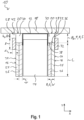
- FIG. 1 a drywall 10 with a drywall profile 12, a stand construction 14 and planking 16 is shown in cross section on each end face.
- the drywall profile 12 is a ceiling profile with a U-shaped cross section, which is firmly anchored to a component 18 extending in the horizontal direction X, for example by means of dowels and screws.
- each end face is fastened to the stand structure 14 at a distance from the component 18, for example by means of screws, thereby creating an expansion joint 20 in the form of a ceiling joint in the vertical direction Y between a peripheral side 22 of the corresponding paneling 16 and the component 18 is formed.
- the stand structure 14 is movably attached to the drywall profile 12 in the vertical direction Y over a distance S, which corresponds in its length and orientation to an intended maximum movement absorption F.
- the drywall profile 12 can have corresponding elongated holes which extend in the vertical direction Y and in which the stand structure 14 is slidably mounted via fasteners, such as screws.
- each end face of the drywall 10 is formed in the present embodiment by a first planking part 26 and a second planking part 24, which rest against one another in the horizontal direction X across their end faces.
- each paneling 16 is a two-layer paneling.
- planking parts 24, 26 are drywall panels, such as plasterboard or gypsum fiber panels.
- the paneling parts 24, 26 each have a wall thickness w in the horizontal direction X and a height L in the vertical direction Y.
- Each paneling 16 thus has a total wall thickness W in the horizontal direction X, which corresponds to twice the wall thickness w.
- the movement joints 20 therefore each have a width G in the horizontal direction X, which corresponds to the total wall thickness W of the paneling 16.
- the paneling parts 24, 26 of each paneling 16 end at the same height in the vertical direction Y and thus form a substantially flat peripheral side 22 of the corresponding paneling 16.
- the first paneling part 26 and the second paneling part 24 are not arranged vertically offset from one another.
- the drywall 10 can have paneling 16 only on one end face.
- each paneling 16 can have any number of layers or paneling parts 24, 26.
- paneling parts 24, 26 can each consist of any material and/or have any dimensions.
- the drywall 10 has a sealing device 28 for each movement joint 20.
- component 18 is a ceiling.
- the component 18 can be any component, for example a crossbar.
- sealing device 28 is also suitable for sealing an expansion joint 20 between the drywall 10 and a wall and/or a floor, which in particular extend perpendicular to the drywall 10 analogously to the component 18.
- sealing devices 28 are designed identically here, the structure of the sealing devices 28 will be described below using a sealing device 28 as an example.
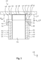
- the sealing device 28 comprises a sealing profile 30, which is arranged in the movement joint 20, and a protective plate 32, which is on the outer end face 34 of the paneling 16 with an offset V (see Figure 3 ) is attached opposite the peripheral side 22.
- the protective plate 32 is a plasterboard panel with a height I in the vertical direction Y, and is shaped in such a way that it can be securely fastened in the stand structure 14.
- the protective plate 32 has a minimum height of approximately 100 mm. This allows a screw, such as a drywall screw, to be securely fastened in the stand structure 14.
- An ordinary drywall profile 12 typically has a height of around 50 mm; However, the protective plate 32 should always have a greater height I than the drywall profile height. The screw in the protective plate 32 must be positioned so that even with a compressed joint, the screw does not abut the drywall profile 12.
- the protective plate 32 is a plasterboard with a height I in the vertical direction Y, and a wall thickness d in the horizontal direction
- the protective plate 32 can consist of any desired, preferably inorganic, material, for example metal; Plaster or cement are also conceivable.
- the protective plate 32 can have a height I that corresponds to less than 50% of the length L of the paneling 16, in particular less than 20%.
- the protective plate 32 can have a wall thickness d that corresponds to less than 25% of the total wall thickness W of the paneling 16.
- the sealing profile 30 consists of a foam, which can optionally include an intumescent material.
- a functional element made of intumescent material can be attached to the sealing profile 30.
- the sealing profile 30 has a rectangular cross section with a width B in the horizontal direction
- the sealing profile 30 can have a width B that is between 100% and 110% of the total wall thickness W of the paneling 16, and/or a height H that is between 100% and 110% of the intended maximum movement absorption F.
- the sealing profile 30 has a lateral contact surface 36, on which the protective plate 32 rests on the front side, as well as a contact surface 38, which lies opposite the peripheral side 22 and on which the paneling 16 rests over the peripheral side 22 in certain positions of the component 18, as described below is.
- the sealing profile 30 can have any cross-section, as long as it is guaranteed that the sealing profile 30 reliably seals the expansion joint 20 in all positions of the drywall 10 or the component 18 for which the sealing device 28 is intended.
- the drywall 10 is designed in such a way that the expansion of the movement joint 20 adapts in the vertical direction Y when the component 18 is in a neutral position (see Figure 1 ) lowers in the vertical direction Y (see Figure 2 ) or lifts (see Figure 3 ), for example due to weight loads and/or thermal expansion.
- the direction of expansion of the movement joint 20 corresponds here to the vertical direction Y.
- the Figure 2 shows the drywall 10 with the component 18 in a position deflected maximally downwards in the vertical direction Y, while the Figure 3 the component 18 shows in a position deflected maximally upwards in the vertical direction Y.
- maximum refers to the positions for which the drywall 10 or the sealing device 28 is designed.
- the movement joint 20 In the neutral position (see Figure 1 ), the movement joint 20 has an extent A N and the paneling 16 lies with the peripheral side 22 on the contact surface 38.
- the protective plate 32 is arranged in the neutral position at a distance D in the vertical direction Y from the component 18.
- the expansion joint 20 In the maximum downwardly deflected position (see Figure 2 ), the expansion joint 20 has an extent A min , with the sealing profile 30 being compressed in the vertical direction Y.
- the sealing profile 30 is attached to the component 18 and/or the drywall profile 12 in a way that does not significantly hinder compression.
- the movement joint 20 In the maximum upwardly deflected position (see Figure 3 ), the movement joint 20 has an extent A max and the planking 16 is no longer in contact with the sealing profile 30, but the peripheral side 22 and the contact surface 38 are separated from each other by a gap 40, which has a height Z in the vertical direction Y.
- the intended maximum movement absorption F is composed of the maximum possible movement b1 in the vertical direction Y and the maximum possible movement b2 against the vertical direction Y, which the planking 16 can carry out relative to the neutral position.
- the distance D, the height Z and the offset V are the same size and each correspond to half of the intended maximum movement absorption F.
- planking 16 and the sealing devices 28 of the two end faces of the drywall 10 are designed analogously to one another, reference will only be made below to one planking 16 and the corresponding sealing device 28.
- the drywall profile 12 is attached to the component 18 in a first step.
- the sealing profile 30 is attached to the component 18 and/or the drywall profile 12 in the movement joint 20, or at the point where the movement joint 20 is formed in the following steps, for example in a materially bonded manner.
- planking 16 is movably fastened to the drywall profile 12 in the vertical direction Y using the screws.
- peripheral side 22 of the paneling 16 is brought into contact with the contact surface 38 of the sealing profile 30, so that the paneling 16 is arranged at a distance A N from the component 18.
- the sealing profile 30 has a height H that is greater than the distance A N , the sealing profile 30 is correspondingly compressed in the vertical direction Y.
- the distance A N corresponds to the maximum intended movement absorption F.
- the protective plate 32 is fastened to the end face 34 of the planking 16 at a distance D from the component 18 and at an offset V from the paneling 16.
- the protective plate 32 comes into contact at the front with the side contact surface 36 of the sealing profile 30, which is accordingly compressed in the horizontal direction case is.
- the sealing profile 30 is essentially only arranged in the movement joint 20 and does not protrude beyond it, in particular not into the gap 42 between the protective plate 32 and the component 18.
- the distance D corresponds to half of the maximum intended movement absorption F.
- the sealing profile 30 is only inserted into the expansion joint 20 after the paneling 16 has been attached.
- the sealing profile 30 is attached to the component 18 in front of the drywall profile 12 or together with it.
- a drywall 10 and a method for producing a drywall 10 are provided, which has a particularly effective and compact sealing device 28 for sealing the expansion joint 20.
- the sealing device 28 is designed in such a way that the sealing profile 30 is compressed by a maximum of 50% in the vertical direction Y. This ensures that the sealing profile 30 made of foam is only deformed elastically and is therefore not damaged.
- the offset Z corresponds to half of the maximum intended movement absorption F and the sealing profile 30 has a height H which corresponds at least to the maximum intended movement absorption F ensures that the movement joint 20 is reliably protected by the sealing device 28 in all positions of the component 18 is sealed.
- the drywall 10 can be manufactured or assembled using the method with little effort.
Landscapes
- Engineering & Computer Science (AREA)
- Architecture (AREA)
- Physics & Mathematics (AREA)
- Electromagnetism (AREA)
- Civil Engineering (AREA)
- Structural Engineering (AREA)
- Building Environments (AREA)
Abstract
Eine Trockenbauwand (10) hat einer Beplankung (16) und eine Dichtvorrichtung (28) zum Abdichten einer Bewegungsfuge (20) zwischen einer Umfangsseite (22) der Beplankung (16) und einem angrenzenden Bauteil (18). Die Dichtvorrichtung (28) weist ein Dichtprofil (30) aus einem Schaumstoff und eine Schutzplatte (32) auf, die mit einem Versatz gegenüber der Beplankung (16) so angeordnet ist, dass die Schutzplatte (32) das Dichtprofil (30) und die Beplankung (16) stirnseitig überlappt. Hierbei hat die Schutzplatte (32) eine Wandstärke (d), die weniger als 80 % einer Gesamtwandstärke (W) der Beplankung (16) beträgt. Des Weiteren ist ein Verfahren zum Herstellen einer solchen Trockenbauwand (10) vorgesehen.A drywall (10) has a paneling (16) and a sealing device (28) for sealing an expansion joint (20) between a peripheral side (22) of the paneling (16) and an adjacent component (18). The sealing device (28) has a sealing profile (30) made of foam and a protective plate (32), which is arranged at an offset from the paneling (16) so that the protective plate (32) covers the sealing profile (30) and the paneling (16) overlapped at the front. The protective plate (32) has a wall thickness (d) that is less than 80% of a total wall thickness (W) of the paneling (16). Furthermore, a method for producing such a drywall (10) is provided.
Description
Die Erfindung betrifft eine Trockenbauwand mit einem Trockenbauprofil, einer Ständerkonstruktion, einer Beplankung und einer Dichtvorrichtung zum Abdichten einer Bewegungsfuge zwischen einer Umfangsseite der Beplankung und einem angrenzenden Bauteil. Des Weiteren betrifft die Erfindung ein Verfahren zum Herstellen einer solchen Trockenbauwand.The invention relates to a drywall with a drywall profile, a stand construction, a paneling and a sealing device for sealing an expansion joint between a peripheral side of the paneling and an adjacent component. The invention further relates to a method for producing such a drywall.
Trockenbauwände mit Bewegungsfugen sowie deren Herstellung sind bekannt.Drywall walls with movement joints and their production are known.
Bewegungsfugen befinden sich üblicherweise im Anschlussbereich zur Geschossdecke und ggf. zu Massivwänden. Durch Gewichtsbelastung oder thermische Einflüsse kann es bei Gebäuden zu einem Senken oder Heben der Decke kommen. Um Beschädigungen der Trockenbauwand zu vermeiden, wird in diesem Fall die obere Anschlussfuge als Bewegungsfuge ausgeführt. Das Trockenbauprofil ist dabei derart ausgebildet, dass eine Relativbewegung zwischen Trockenbauprofil und der Beplankung der Trockenbauwand möglich ist. Zur Abdichtung der Bewegungsfuge wird entweder eine geeignete Dichtmasse eingebracht oder aber der Spalt mit Mineralwolle gefüllt und an der Oberfläche mit einer abdichtenden Schicht versehen. Seit einiger Zeit gibt es jedoch auch zunehmend Dichtelemente, die vorgefertigt auf das Trockenbauprofil aufgebracht werden. Diese Dichtelemente sind meist intumeszierend. Die Intumeszens ersetzt im Brandfall die Beplankung, d. h. normalerweise ein oder mehrere Trockenbauplatten, wie Gipskartonplatten oder Gipsfaserplatten, und dichtet somit die Bewegungsfuge in diesem Bereich sicher ab.Movement joints are usually located in the connection area to the floor ceiling and, if necessary, to solid walls. Weight loads or thermal influences can cause the ceiling of buildings to sink or rise. In order to avoid damage to the drywall, in this case the upper connection joint is designed as an expansion joint. The drywall profile is designed in such a way that a relative movement between the drywall profile and the cladding of the drywall is possible. To seal the expansion joint, either a suitable sealant is applied or the gap is filled with mineral wool and provided with a sealing layer on the surface. For some time now, however, there have been increasing numbers of sealing elements that are prefabricated and applied to the drywall profile. These sealing elements are usually intumescent. In the event of a fire, the intumescence replaces the planking, i.e. H. usually one or more drywall panels, such as plasterboard or gypsum fiberboard, and thus securely seals the expansion joint in this area.
In all diesen Fällen behindert das in der Fuge befindliche Material die Bewegung relativ stark, mit der Konsequenz, dass zur Erzielung einer ausreichenden Bewegungsaufnahme mit verhältnismäßig großen Fugenbreiten gearbeitet werden muss. Hierdurch sind bekannte Dichtvorrichtungen zum Abdichten von Bewegungsfugen häufig sehr voluminös, insbesondere um den hohen Anforderungen des Brandschutzes zu entsprechen.In all of these cases, the material in the joint hinders movement relatively severely, with the consequence that relatively large joint widths must be used to achieve sufficient movement absorption. As a result, known sealing devices for sealing expansion joints are often very voluminous, in particular in order to meet the high requirements of fire protection.
Aufgabe der Erfindung ist es, eine Trockenbauwand mit einer Bewegungsfuge bereitzustellen, die besonders kompakt und materialeffizient gestaltet ist. Aufgabe der Erfindung ist es ferner, ein Verfahren zum Herstellen einer solchen Trockenbauwand bereitzustellen.The object of the invention is to provide a drywall with an expansion joint that is designed to be particularly compact and material-efficient. The object of the invention is also to provide a method for producing such a drywall.
Die Aufgabe wird gelöst durch eine Trockenbauwand mit einem Trockenbauprofil, einer Ständerkonstruktion, einer Beplankung und einer Dichtvorrichtung zum Abdichten einer Bewegungsfuge zwischen einer Umfangsseite der Beplankung und einem angrenzenden Bauteil, insbesondere einer Decke. Die Bewegungsfuge hat eine vorgesehene maximale Bewegungsaufnahme in einer Ausdehnungsrichtung. Ferner ist die Beplankung mittels Schrauben am Trockenbauprofil befestigt. Die Dichtvorrichtung weist dabei ein Dichtprofil aus einem Schaumstoff und eine Schutzplatte auf. Das Dichtprofil ist ferner in der Bewegungsfuge angeordnet und die Schutzplatte ist mit einem Versatz gegenüber der Beplankung so angeordnet, dass die Schutzplatte das Dichtprofil und die Beplankung stirnseitig überlappt. Die Schutzplatte hat hierbei eine Wandstärke, die weniger als 80 %, vorzugsweise weniger als 60 %, einer Gesamtwandstärke der Beplankung beträgt. Die vorgesehene maximale Bewegungsaufnahme entspricht dabei der Summe aus der vorgesehenen maximal möglichen Bewegung in Ausdehnungsrichtung und der vorgesehenen maximal möglichen Bewegung entgegen der Ausdehnungsrichtung, jeweils gegenüber einer Neutralstellung. Die Wandstärke entspricht hierbei der Nennwandstärke der plattenförmigen Schutzplatte bzw. der Beplankung, d. h. lokale Strukturen mit geringerer Wandstärke, wie Bohrlöcher oder Materialschwächungen, bleiben unberücksichtigt.The task is solved by a drywall with a drywall profile, a stand construction, a planking and a sealing device for sealing an expansion joint between a peripheral side of the planking and an adjacent component, in particular a ceiling. The movement joint has an intended maximum movement absorption in one direction of expansion. Furthermore, the planking is attached to the drywall profile using screws. The sealing device has a sealing profile made of foam and a protective plate. The sealing profile is also arranged in the movement joint and the protective plate is arranged with an offset from the planking so that the protective plate overlaps the sealing profile and the planking on the front side. The protective plate has a wall thickness that is less than 80%, preferably less than 60%, of the total wall thickness of the paneling. The intended maximum movement absorption corresponds to the sum of the intended maximum possible movement in the direction of expansion and the intended maximum possible movement against the direction of expansion, in each case compared to a neutral position. The wall thickness corresponds to the nominal wall thickness of the plate-shaped protective plate or the paneling, i.e. H. Local structures with thinner walls, such as drill holes or weakened materials, are not taken into account.
Es wurde erfindungsgemäß erkannt, dass das Dichtprofil besonders kompakt gestaltet werden kann, indem mittels der Schutzplatte ein Abschnitt der Bewegungsfuge außenseitig abgedeckt wird. Die Schutzplatte ist dabei so angeordnet, dass sie die vorgesehene maximal mögliche Bewegung der Beplankung nicht einschränkt und einen Spalt schützend überdeckt, der sich zwischen der Beplankung und dem Dichtprofil im Rahmen der vorgesehenen maximal möglichen Relativbewegung der Beplankung bzw. des Bauteils bilden kann. Ferner ist die Schutzplatte im Vergleich zur Beplankung besonders dünn ausgebildet, so dass die Trockenbauwand besonders materialeffizient gestaltet ist und die Schutzplatte weniger stark aufträgt. Hierdurch hat die Dichtvorrichtung einen geringeren Raumbedarf und bietet mehr Freiheit bei der Gestaltung der Trockenbauwand.It was recognized according to the invention that the sealing profile can be made particularly compact by covering a section of the expansion joint on the outside using the protective plate. The protective plate is arranged in such a way that it does not restrict the intended maximum possible movement of the paneling and protectively covers a gap that can form between the paneling and the sealing profile within the scope of the intended maximum possible relative movement of the paneling or the component. Furthermore, the protective plate is particularly thin compared to the planking, so that the drywall is designed to be particularly material-efficient and the protective plate is less bulky. As a result, the sealing device requires less space and offers more freedom in the design of the drywall.
Insbesondere ist die Dichtvorrichtung dazu eingerichtet, die Bewegungsfuge akustisch, rauchsicher und/oder brandsicher abzudichten.In particular, the sealing device is designed to seal the expansion joint acoustically, smoke-proof and/or fire-proof.
In einer Ausführungsform hat das Dichtprofil eine Höhe in Ausdehnungsrichtung, die zwischen 100 % und 110 % der maximal vorgesehenen Bewegungsaufnahme entspricht, und/oder eine Breite, die zwischen 100 % und 110 % der Gesamtwandstärke der Beplankung entspricht. Auf diese Weise ist das Dichtprofil besonders kompakt und die Dichtvorrichtung materialeffizient gestaltet. Ferner stellt eine Höhe in Ausdehnungsrichtung zwischen 100 % und 110 % der maximal vorgesehenen Bewegungsaufnahme sicher, dass das Dichtprofil bei allen vorgesehenen Bewegungsaufnahmen bzw. Fugenbreiten der Bewegungsfuge um weniger als 70 % komprimiert wird. Da Schaumstoffe nur eine begrenzte Komprimierbarkeit aufweisen, ist auf diese Weise sichergestellt, dass das Dichtprofil lediglich elastisch und nicht plastisch verformt wird. Somit werden eine Beschädigung der Zellstruktur des Dichtprofils vermieden und eine zuverlässige Abdichtung der Bewegungsfuge dauerhaft gewährleistet.In one embodiment, the sealing profile has a height in the direction of expansion that corresponds to between 100% and 110% of the maximum intended movement absorption, and/or a width that corresponds to between 100% and 110% of the total wall thickness of the paneling. In this way, the sealing profile is particularly compact and the sealing device is designed to be material-efficient. Furthermore, a height in the direction of expansion between 100% and 110% of the maximum intended movement absorption ensures that the sealing profile is compressed by less than 70% for all intended movement absorption or joint widths of the movement joint. Since foams only have a limited compressibility, this ensures that the sealing profile is only deformed elastically and not plastically. This prevents damage to the cell structure of the sealing profile and ensures long-term reliable sealing of the expansion joint.
Zusätzlich oder alternativ kann das Dichtprofil eine Kontaktfläche, die der Umfangsseite der Beplankung gegenüberliegt, und eine seitliche Anlagefläche haben, an der die Schutzplatte stirnseitig anliegt. Durch diese Gestaltung wird sichergestellt, dass die Bewegungsfuge durch die Dichtvorrichtung zuverlässig abgedichtet wird, insbesondere rauch- und schalldicht.Additionally or alternatively, the sealing profile can have a contact surface that lies opposite the peripheral side of the paneling and a lateral contact surface against which the protective plate rests on the front side. This design ensures that the movement joint is reliably sealed by the sealing device, in particular smoke and soundproof.
Ferner kann vorgesehen sein, dass die Beplankung eine zweilagige Beplankung mit einem ersten Beplankungsteil und einem zweiten Beplankungsteil ist, insbesondere wobei das erste Beplankungsteil und das zweite Beplankungsteil dieselben Abmessungen haben. Durch die zweilagige Beplankung hat die Beplankung eine größere Gesamtwandstärke und ist somit massiver gestaltet, so dass sie im Vergleich zu einer Trockenbauwand mit einer einfachen Beplankung bessere Brandschutzeigenschaften aufweist. Indem das erste Beplankungsteil und das zweite Beplankungsteil dieselben Abmessungen haben, können Gleichteile für beide Lagen der Beplankung verwendet werden, was wiederum Vorteile in der Logistik bietet und geringere Herstellkosten begünstigt.Furthermore, it can be provided that the planking is a two-layer planking with a first planking part and a second planking part, in particular where the first planking part and the second planking part have the same dimensions. Due to the two-layer planking, the planking has a greater overall wall thickness and is therefore more solid, so that it has better fire protection properties compared to a drywall with simple planking. Since the first paneling part and the second paneling part have the same dimensions, identical parts can be used for both layers of the paneling, which in turn offers advantages in logistics and promotes lower manufacturing costs.
Gemäß einer Ausführungsform hat die Schutzplatte eine Länge in Ausdehnungsrichtung, die weniger als 50 % der Länge in Ausdehnungsrichtung der Beplankung beträgt, wodurch die Schutzplatte besonders kompakt gestaltet ist.According to one embodiment, the protective plate has a length in the direction of expansion that is less than 50% of the length in the direction of expansion of the paneling, as a result of which the protective plate is designed to be particularly compact.
Gemäß einer weiteren Ausführungsform besteht die Schutzplatte aus Metall, Gips oder Zement, vorzugsweise aus Metall, wodurch sie besonders gute Brandschutzeigenschaften aufweist.According to a further embodiment, the protective plate is made of metal, plaster or cement, preferably metal, which means that it has particularly good fire protection properties.
Zusätzlich oder alternativ kann die Wandstärke der Schutzplatte weniger als 25 % der Gesamtwandstärke der Beplankung betragen, so dass die Schutzplatte besonders dünn ist und somit gegenüber der Beplankung stirnseitig nur geringfügig aufträgt bzw. von dieser absteht.Additionally or alternatively, the wall thickness of the protective plate can be less than 25% of the total wall thickness of the planking, so that the protective plate is particularly thin and therefore only slightly intrusive on the front side of the planking or protrudes from it.
Erfindungsgemäß ist zur Lösung der oben genannten Aufgabe auch ein Verfahren zum Herstellen einer erfindungsgemäßen Trockenbauwand mit den zuvor genannten Vorteilen vorgesehen. Das Verfahren umfasst die folgenden Schritte:
- a) Anbringen des Trockenbauprofils am Bauteil,
- b) Befestigen der Beplankung am Trockenbauprofil mittels Schrauben, wobei die Beplankung gegenüber dem Trockenbauprofil in Ausdehnungsrichtung verstellbar bleibt,
- c) Anordnen des Dichtprofils in der Bewegungsfuge oder an der Stelle, an der die Bewegungsfuge beim Herstellen der Trockenbauwand gebildet wird, und
- d) Befestigen der Schutzplatte.
- a) attaching the drywall profile to the component,
- b) Attaching the planking to the drywall profile using screws, whereby the planking remains adjustable in the direction of expansion relative to the drywall profile,
- c) Arranging the sealing profile in the movement joint or at the point where the movement joint is formed when the drywall is manufactured, and
- d) Attaching the protective plate.
Die Reihenfolge der Schritte ist dabei im Wesentlichen beliebig. Beispielsweise kann der Schritt c) vor dem Schritt a), zwischen den Schritten a) und b) oder nach dem Schritt b) erfolgen.The order of the steps is essentially arbitrary. For example, step c) can take place before step a), between steps a) and b) or after step b).
In einer Ausführungsform erfolgt das Befestigen der Schutzplatte nach den Schritten a) bis c), da auf diese Weise mit besonders wenig Aufwand sichergestellt werden kann, dass die Schutzplatte wirkungsvoll angeordnet ist.In one embodiment, the protective plate is fastened after steps a) to c), since in this way it can be ensured with particularly little effort that the protective plate is arranged effectively.
In einer weiteren Ausführungsform wird die Schutzplatte in einem Abstand gegenüber dem Bauteil montiert, der der halben maximal vorgesehenen Bewegungsaufnahme entspricht. Somit schränkt die Dichtvorrichtung die vorgesehene maximal mögliche Bewegung der Beplankung nicht ein und dichtet die Bewegungsfuge zuverlässig über die gesamte vorgesehene maximale Bewegungsaufnahme ab.In a further embodiment, the protective plate is mounted at a distance from the component that corresponds to half the maximum intended movement absorption. The sealing device therefore does not restrict the intended maximum possible movement of the planking and reliably seals the movement joint over the entire intended maximum movement absorption.
Zusätzlich oder alternativ kann die Beplankung in einem Abstand gegenüber dem Bauteil montiert werden, der der maximal vorgesehenen Bewegungsaufnahme entspricht. Somit wird das Dichtprofil durch die Beplankung maximal nur in einem Maße komprimiert, das eine Beschädigung des Dichtprofils vermeidet, insbesondere wenn das Dichtprofil eine Höhe in Ausdehnungsrichtung hat, die weniger als 150 % der maximal vorgesehenen Bewegungsaufnahme beträgt.Additionally or alternatively, the paneling can be mounted at a distance from the component that corresponds to the maximum intended movement absorption. The sealing profile is therefore only compressed by the planking to a maximum extent that avoids damage to the sealing profile, especially if the sealing profile has a height in the direction of expansion that is less than 150% of the maximum intended movement absorption.
Weitere Vorteile und Merkmale ergeben sich aus der nachfolgenden Beschreibung sowie aus den beigefügten Zeichnungen. In diesen zeigen:
-
Figur 1 in einer schematischen Schnittansicht eine erfindungsgemäße Trockenbauwand und ein Bauteil in einer Neutralstellung, -
Figur 2 in einer schematischen Schnittansicht die Trockenbauwand ausFigur 1 mit dem Bauteil in einer maximal nach unten ausgelenkten Stellung, und -
Figur 3 in einer schematischen Schnittansicht die Trockenbauwand ausFigur 1 mit dem Bauteil in einer maximal nach oben ausgelenkten Stellung.
-
Figure 1 in a schematic sectional view a drywall according to the invention and a component in a neutral position, -
Figure 2 in a schematic sectional view of the drywallFigure 1 with the component in a maximum downwardly deflected position, and -
Figure 3 in a schematic sectional view of the drywallFigure 1 with the component in a maximum upwardly deflected position.
In
Im vorliegenden Fall ist das Trockenbauprofil 12 ein Deckenprofil mit U-förmigem Querschnitt, das an einem sich in horizontaler Richtung X erstreckenden Bauteil 18 fest verankert ist, beispielsweise mittels Dübel und Schrauben.In the present case, the
Die Beplankung 16 jeder Stirnseite ist beabstandet von dem Bauteil 18 an der Ständerkonstruktion 14 befestigt, beispielsweise mittels Schrauben, wodurch jeweils eine Bewegungsfuge 20 in Form einer Deckenfuge in vertikaler Richtung Y zwischen einer Umfangsseite 22 der entsprechenden Beplankung 16 und dem Bauteil 18 gebildet ist.The
Die Ständerkonstruktion 14 ist hierbei am Trockenbauprofil 12 in vertikaler Richtung Y über eine Strecke S beweglich befestigt, die in ihrer Länge und Ausrichtung einer vorgesehenen maximalen Bewegungsaufnahme F entspricht.The stand structure 14 is movably attached to the
Hierzu kann das Trockenbauprofil 12 in eine Ausführungsform entsprechende Langlöcher aufweisen, die sich in vertikaler Richtung Y erstrecken und in denen die Ständerkonstruktion 14 über Befestigungsmittel, wie Schrauben, verschiebbar gelagert ist.For this purpose, in one embodiment, the
Die Beplankung 16 jeder Stirnseite der Trockenbauwand 10 wird in der vorliegenden Ausführungsform durch ein erstes Beplankungsteil 26 und ein zweites Beplankungsteil 24 gebildet, die in horizontaler Richtung X über ihre Stirnseiten aneinander anliegen. Mit anderen Worten ist jede Beplankung 16 eine zweilagige Beplankung.The
In diesem Zusammenhang sind die Beplankungsteile 24, 26 Trockenbauplatten, wie Gipskartonplatten oder Gipsfaserplatten.In this context, the
Ferner haben die Beplankungsteil 24, 26 jeweils eine Wandstärke w in horizontaler Richtung X sowie eine Höhe L in vertikaler Richtung Y.Furthermore, the
Jede Beplankung 16 hat somit eine Gesamtwandstärke W in horizontaler Richtung X, die der zweifachen Wandstärke w entspricht.Each
Die Bewegungsfugen 20 haben daher jeweils eine Breite G in horizontaler Richtung X, die der Gesamtwandstärke W der Beplankung 16 entspricht.The movement joints 20 therefore each have a width G in the horizontal direction X, which corresponds to the total wall thickness W of the
Die Beplankungsteile 24, 26 jeder Beplankung 16 schließt in vertikaler Richtung Y auf derselben Höhe ab und bilden somit eine im Wesentlichen ebene Umfangsseite 22 der entsprechenden Beplankung 16. Mit anderen Worten sind das erste Beplankungsteil 26 und das zweite Beplankungsteil 24 nicht vertikal versetzt zueinander angeordnet.The
Selbstverständlich kann die Trockenbauwand 10 in einer alternativen Ausführungsform lediglich auf einer Stirnseite eine Beplankung 16 aufweisen.Of course, in an alternative embodiment, the
Zusätzlich oder alternativ kann jede Beplankung 16 eine beliebige Anzahl an Lagen bzw. Beplankungsteilen 24, 26 aufweisen.Additionally or alternatively, each
Ferner können die Beplankungsteile 24, 26 jeweils aus einem beliebigen Material bestehen und/oder beliebige Abmessungen aufweisen.Furthermore, the
Um die Bewegungsfugen 20 abzudichten, weist die Trockenbauwand 10 für jede Bewegungsfuge 20 eine Dichtvorrichtung 28 auf.In order to seal the movement joints 20, the
In diesem Zusammenhang ist das Bauteil 18 eine Decke.In this context,
Grundsätzlich kann das Bauteil 18 ein beliebiges Bauteil sein, beispielsweise ein Querbalken.In principle, the
Ferner ist die Dichtvorrichtung 28 auch zur Abdichtung einer Bewegungsfuge 20 zwischen der Trockenbauwand 10 und einer Wand und/oder einem Boden geeignet, die insbesondere analog zum Bauteil 18 senkrecht zur Trockenbauwand 10 verlaufen.Furthermore, the sealing
Da die Dichtvorrichtungen 28 hier identisch gestaltet sind, wird im Folgenden der Aufbau der Dichtvorrichtungen 28 beispielhaft anhand einer Dichtvorrichtung 28 beschrieben.Since the
Die Dichtvorrichtung 28 umfasst ein Dichtprofil 30, das in der Bewegungsfuge 20 angeordnet ist, und eine Schutzplatte 32, die an der außenliegenden Stirnseite 34 der Beplankung 16 mit einem Versatz V (siehe
In der vorliegenden Ausführungsform ist die Schutzplatte 32 eine Gipskartonplatte mit einer Höhe I in vertikaler Richtung Y, und so ausgeformt, dass sich diese sicher in der Ständerkonstruktion 14 befestigen lässt. Idealerweise hat die Schutzplatte 32 eine Mindesthöhe von ca. 100 mm. Damit lässt sich sicher eine Schraube, wie beispielweise eine Trockenbauschraube, in der Ständerkonstruktion 14 befestigen. Ein gewöhnliches Trockenbauprofil 12 hat typischerweise eine Höhe von etwa 50 mm; jedoch sollte die Schutzplatte 32 immer eine größere Höhe I haben als die Trockenbauprofilhöhe. Die Schraube in der Schutzplatte 32 muss so positioniert sein, dass selbst bei einer komprimierten Fuge, die Schraube nicht an dem Trockenbauprofil 12 anstößt.In the present embodiment, the
Vorzugweise ist die Schutzplatte 32 eine Gipskartonplatte mit einer Höhe I in vertikaler Richtung Y, und einer Wandstärke d in horizontaler Richtung X, die der Wandstärke w der Beplankungsteile 24, 26 bzw. der halben Gesamtwandstärke W der Beplankung 16 entspricht.Preferably, the
Grundsätzlich kann die Schutzplatte 32 aus einem beliebigen, vorzugsweise anorganischen Material bestehen, beispielsweise aus Metall; denkbar sind auch Gips oder Zement.In principle, the
In einer alternativen Ausführungsform kann die Schutzplatte 32 eine Höhe I haben, die weniger als 50 % der Länge L der Beplankung 16 entspricht, insbesondere weniger als 20 %.In an alternative embodiment, the
Zusätzlich oder alternativ kann die Schutzplatte 32 eine Wandstärke d haben, die weniger als 25 % der Gesamtwandstärke W der Beplankung 16 entspricht.Additionally or alternatively, the
Das Dichtprofil 30 besteht aus einem Schaumstoff, der optional ein intumeszierendes Material umfassen kann.The sealing
Zusätzlich oder alternativ kann ein Funktionselement aus intumeszierenden Material am Dichtprofil 30 befestigt sein.Additionally or alternatively, a functional element made of intumescent material can be attached to the sealing
In der dargestellten Ausführungsform hat das Dichtprofil 30 einen rechteckigen Querschnitt mit einer Breite B in horizontaler Richtung X, die 105 % der Gesamtwandstärke W der Beplankung 16 entspricht, und einer Höhe H in vertikaler Richtung Y, die 100 % der vorgesehenen maximalen Bewegungsaufnahme F entspricht.In the illustrated embodiment, the sealing
In einer alternativen Ausführungsformkann das Dichtprofil 30 eine Breite B haben, die zwischen 100 % und 110 % der Gesamtwandstärke W der Beplankung 16 beträgt, und/oder eine Höhe H haben, die zwischen 100 % und 110 % der vorgesehenen maximalen Bewegungsaufnahme F beträgt.In an alternative embodiment, the sealing
Des Weiteren hat das Dichtprofil 30 eine seitliche Anlagefläche 36, an der die Schutzplatte 32 stirnseitig anliegt, sowie eine Kontaktfläche 38, die der Umfangsseite 22 gegenüberliegt und an der die Beplankung 16 über die Umfangsseite 22 in bestimmten Stellungen des Bauteils 18 anliegt, wie nachfolgend beschrieben ist.Furthermore, the sealing
Grundsätzlich kann das Dichtprofil 30 einen beliebigen Querschnitt aufweisen, solange gewährleistet ist, dass das Dichtprofil 30 die Bewegungsfuge 20 in allen Stellungen der Trockenbauwand 10 bzw. des Bauteils 18 zuverlässig abgedichtet, für die die Dichtvorrichtung 28 vorgesehen ist.In principle, the sealing
Die Trockenbauwand 10 ist hierbei so gestaltet, dass sich die Ausdehnung der Bewegungsfuge 20 in vertikaler Richtung Y anpasst, wenn sich das Bauteil 18 gegenüber einer Neutralstellung (siehe
Die Ausdehnungsrichtung der Bewegungsfuge 20 entspricht hier der vertikalen Richtung Y.The direction of expansion of the movement joint 20 corresponds here to the vertical direction Y.
Die
In der Neutralstellung (siehe
Die Schutzplatte 32 ist in der Neutralstellung in einem Abstand D in vertikaler Richtung Y zum Bauteil 18 angeordnet.The
In der maximal nach unten ausgelenkten Stellung (siehe
Das Dichtprofil 30 ist hierbei am Bauteil 18 und/oder dem Trockenbauprofil 12 auf eine Weise befestigt, die die Komprimierung nicht wesentlich behindert.The sealing
In der maximal nach oben ausgelenkten Stellung (siehe
In diesem Zusammenhang setzt sich die vorgesehene maximale Bewegungsaufnahme F aus der maximal möglichen Bewegung b1 in vertikaler Richtung Y und der maximal möglichen Bewegung b2 entgegen der Vertikalrichtung Y zusammen, die die Beplankung 16 gegenüber der Neutralstellung durchführen kann.In this context, the intended maximum movement absorption F is composed of the maximum possible movement b1 in the vertical direction Y and the maximum possible movement b2 against the vertical direction Y, which the
In der vorliegenden Ausführungsform sind der Abstand D, die Höhe Z und der Versatz V gleich groß und entsprechen jeweils der Hälfte der vorgesehenen maximalen Bewegungsaufnahme F.In the present embodiment, the distance D, the height Z and the offset V are the same size and each correspond to half of the intended maximum movement absorption F.
Im Folgenden wird ein Verfahren zur Herstellung der Trockenbauwand 10 am Bauteil 18 beschrieben, das sich hierbei in der Neutralstellung befindet. Da die Beplankungen 16 und die Dichtvorrichtungen 28 der beiden Stirnseiten der Trockenbauwand 10 analog zu einander gestaltet sind, wird nachfolgend nur Bezug auf eine Beplankung 16 und die entsprechende Dichtvorrichtung 28 genommen.The following describes a method for producing the
Um die Trockenbauwand 10 herzustellen, wird in einem ersten Schritt das Trockenbauprofil 12 am Bauteil 18 befestigt.In order to produce the
Nachfolgend wird das Dichtprofil 30 in der Bewegungsfuge 20, bzw. an der Stelle, an der die Bewegungsfuge 20 in den folgenden Schritten gebildet wird, am Bauteil 18 und/oder dem Trockenbauprofil 12 befestigt, beispielsweise stoffschlüssig.Subsequently, the sealing
In einem nächsten Schritt wird die Beplankung 16 mittels der Schrauben am Trockenbauprofil 12 in vertikaler Richtung Y beweglich befestigt.In a next step, the
Hierbei wird die Umfangsseite 22 der Beplankung 16 mit der Kontaktfläche 38 des Dichtprofils 30 in Kontakt gebracht, so dass die Beplankung 16 im Abstand AN zum Bauteil 18 angeordnet ist.Here, the
Bei Ausführungsformen, bei denen das Dichtprofil 30 eine Höhe H hat, die größer ist als der Abstand AN, wird das Dichtprofil 30 dabei entsprechend in vertikaler Richtung Y komprimiert.In embodiments in which the sealing
In diesem Zusammenhang entspricht der Abstand AN der maximal vorgesehenen Bewegungsaufnahme F.In this context, the distance A N corresponds to the maximum intended movement absorption F.
Schließlich wird die Schutzplatte 32 im Abstand D gegenüber dem Bauteil 18 sowie mit dem Versatz V gegenüber der Beplankung 16 an der Stirnseite 34 der Beplankung 16 befestigt.Finally, the
Hierbei gelangt die Schutzplatte 32 stirnseitig in Anlage mit der seitlichen Anlagefläche 36 des Dichtprofils 30, das dabei entsprechend in horizontaler Richtung X komprimiert wird, falls die Breite B des Dichtprofils 30 größer ist als die Gesamtwandstärke W der Beplankung 16, wie dies im vorliegenden Ausführungsbeispiel der Fall ist.Here, the
Auf diese Weise ist das Dichtprofil 30 im Wesentlichen nur in der Bewegungsfuge 20 angeordnet und ragt nicht über diese hinaus, insbesondere nicht in den Zwischenraum 42 zwischen der Schutzplatte 32 und dem Bauteil 18.In this way, the sealing
In diesem Zusammenhang entspricht der Abstand D der Hälfte der maximal vorgesehenen Bewegungsaufnahme F.In this context, the distance D corresponds to half of the maximum intended movement absorption F.
In einer alternativen Ausführungsform wird zur Herstellung der Trockenbauwand 10 das Dichtprofil 30 erst in die Bewegungsfuge 20 eingesetzt, nachdem die Beplankung 16 befestigt ist.In an alternative embodiment, to produce the
In einer weiteren alternativen Ausführungsform wird das Dichtprofil 30 vor dem Trockenbauprofil 12 oder zusammen mit diesem am Bauteil 18 befestigt.In a further alternative embodiment, the sealing
Auf diese Weise ist eine Trockenbauwand 10 sowie ein Verfahren zur Herstellung einer Trockenbauwand 10 bereitgestellt, die eine besonders wirkungsvolle und kompakte Dichtvorrichtung 28 zur Abdichtung der Bewegungsfuge 20 aufweist.In this way, a
Die Dichtvorrichtung 28 ist hierbei derart gestaltet, dass das Dichtprofil 30 in vertikaler Richtung Y maximal um 50 % komprimiert wird. Somit ist sichergestellt, dass das Dichtprofil 30 aus Schaumstoff lediglich elastisch verformt und somit nicht beschädigt wird.The sealing
Dadurch, dass der Versatz Z der Hälfte der maximal vorgesehenen Bewegungsaufnahme F entspricht und das Dichtprofil 30 eine Höhe H hat, die mindestens der maximal vorgesehenen Bewegungsaufnahme F entspricht, ist sichergestellt, dass die Bewegungsfuge 20 in allen Stellungen des Bauteils 18 zuverlässig durch die Dichtvorrichtung 28 abgedichtet ist.The fact that the offset Z corresponds to half of the maximum intended movement absorption F and the sealing
Des Weiteren kann die Trockenbauwand 10 mittels des Verfahrens mit geringem Aufwand hergestellt bzw. montiert werden.Furthermore, the
Die Erfindung ist nicht auf die gezeigte Ausführungsform beschränkt. Insbesondere können einzelne Merkmale einer Ausführungsform beliebig mit Merkmalen anderer Ausführungsformen kombiniert werden, insbesondere unabhängig von den anderen Merkmalen der entsprechenden Ausführungsformen.The invention is not limited to the embodiment shown. In particular, individual features of one embodiment can be combined as desired with features of other embodiments, in particular independently of the other features of the corresponding embodiments.
Claims (10)
Priority Applications (1)
| Application Number | Priority Date | Filing Date | Title |
|---|---|---|---|
| EP22178798.9A EP4293168A1 (en) | 2022-06-14 | 2022-06-14 | Drywall and method for producing drywall |
Applications Claiming Priority (1)
| Application Number | Priority Date | Filing Date | Title |
|---|---|---|---|
| EP22178798.9A EP4293168A1 (en) | 2022-06-14 | 2022-06-14 | Drywall and method for producing drywall |
Publications (1)
| Publication Number | Publication Date |
|---|---|
| EP4293168A1 true EP4293168A1 (en) | 2023-12-20 |
Family
ID=82058125
Family Applications (1)
| Application Number | Title | Priority Date | Filing Date |
|---|---|---|---|
| EP22178798.9A Pending EP4293168A1 (en) | 2022-06-14 | 2022-06-14 | Drywall and method for producing drywall |
Country Status (1)
| Country | Link |
|---|---|
| EP (1) | EP4293168A1 (en) |
Citations (3)
| Publication number | Priority date | Publication date | Assignee | Title |
|---|---|---|---|---|
| EP3056625A1 (en) * | 2015-02-13 | 2016-08-17 | HILTI Aktiengesellschaft | Sealing tape and sealing assembly comprising such a sealing tape |
| US20170260741A1 (en) * | 2016-03-11 | 2017-09-14 | Rectorseal, Llc | Systems and methods for assisting in reducing the spread of fire, smoke or heat in a building |
| EP3553241A1 (en) * | 2018-04-12 | 2019-10-16 | HILTI Aktiengesellschaft | Joint sealing and sealing arrangement for sealing a joint |
-
2022
- 2022-06-14 EP EP22178798.9A patent/EP4293168A1/en active Pending
Patent Citations (3)
| Publication number | Priority date | Publication date | Assignee | Title |
|---|---|---|---|---|
| EP3056625A1 (en) * | 2015-02-13 | 2016-08-17 | HILTI Aktiengesellschaft | Sealing tape and sealing assembly comprising such a sealing tape |
| US20170260741A1 (en) * | 2016-03-11 | 2017-09-14 | Rectorseal, Llc | Systems and methods for assisting in reducing the spread of fire, smoke or heat in a building |
| EP3553241A1 (en) * | 2018-04-12 | 2019-10-16 | HILTI Aktiengesellschaft | Joint sealing and sealing arrangement for sealing a joint |
Similar Documents
| Publication | Publication Date | Title |
|---|---|---|
| EP0581269B1 (en) | External insulating and surface treatment system | |
| EP3256663B1 (en) | Sealing tape with predetermined geometry and sealing assembly comprising such a sealing tape | |
| AT511220A1 (en) | CEILING ELEMENT FOR THE EDUCATION OF BUILDING COVERS | |
| EP0560013A1 (en) | Wooden panel | |
| EP3060725B1 (en) | Breakage-resistant composite material and stud wall, roof or ceiling structure | |
| DE3128165A1 (en) | SOUND-INSULATING WALL CONSTRUCTION SYSTEM FOR INDUSTRIAL BUILDINGS AND CASSETTE PROFILE HERE | |
| WO2022043224A1 (en) | Sealing device for double edge joint, and drywall | |
| EP1525358B1 (en) | Insulating layer consisting of mineral fibres, and building wall | |
| DE102021107507B3 (en) | Insert module for a wall element and wall element with insert module | |
| EP3553241A1 (en) | Joint sealing and sealing arrangement for sealing a joint | |
| EP4293168A1 (en) | Drywall and method for producing drywall | |
| DE9302447U1 (en) | Wooden construction board | |
| EP3085873B1 (en) | Effect panel | |
| DE202021101571U1 (en) | Insert module for one wall element and wall element with insert module | |
| DE9320234U1 (en) | Sealing against the ingress of dangerous gases, especially radon, from the subsoil | |
| EP3015614A1 (en) | Wall panel for dry construction consisting of a wooden material and wall structure and manufacturing method | |
| AT413410B (en) | WOOD BLACKBOARD | |
| EP0106297A2 (en) | Structural element for manufacturing concrete walls, and building wall produced with the same | |
| DE29605209U1 (en) | Joint plate | |
| EP1527237B1 (en) | Insulation element and building wall | |
| DE19916247A1 (en) | Building block system for construction of prefabricated houses includes basic element consisting of three four-sided wooden glued boards with middle board glued to outer and inner boards with offset to form tongue and groove | |
| DE7720341U1 (en) | PANEL TO USE AS CONSTRUCTION CONSTRUCTION ELEMENT | |
| DE102019003036B4 (en) | Thermal insulation assembly | |
| DE202023104429U1 (en) | Fire insulation for cables in buildings | |
| DE8500260U1 (en) | ROOF ELEMENT WITH HIGH AIR SOUND INSULATION |
Legal Events
| Date | Code | Title | Description |
|---|---|---|---|
| PUAI | Public reference made under article 153(3) epc to a published international application that has entered the european phase |
Free format text: ORIGINAL CODE: 0009012 |
|
| STAA | Information on the status of an ep patent application or granted ep patent |
Free format text: STATUS: THE APPLICATION HAS BEEN PUBLISHED |
|
| AK | Designated contracting states |
Kind code of ref document: A1 Designated state(s): AL AT BE BG CH CY CZ DE DK EE ES FI FR GB GR HR HU IE IS IT LI LT LU LV MC MK MT NL NO PL PT RO RS SE SI SK SM TR |
|
| STAA | Information on the status of an ep patent application or granted ep patent |
Free format text: STATUS: REQUEST FOR EXAMINATION WAS MADE |
|
| 17P | Request for examination filed |
Effective date: 20240620 |
|
| RBV | Designated contracting states (corrected) |
Designated state(s): AL AT BE BG CH CY CZ DE DK EE ES FI FR GB GR HR HU IE IS IT LI LT LU LV MC MK MT NL NO PL PT RO RS SE SI SK SM TR |