EP4292901A1 - Verfahren für ein materialhandhabungsfahrzeug - Google Patents
Verfahren für ein materialhandhabungsfahrzeug Download PDFInfo
- Publication number
- EP4292901A1 EP4292901A1 EP23179653.3A EP23179653A EP4292901A1 EP 4292901 A1 EP4292901 A1 EP 4292901A1 EP 23179653 A EP23179653 A EP 23179653A EP 4292901 A1 EP4292901 A1 EP 4292901A1
- Authority
- EP
- European Patent Office
- Prior art keywords
- platform
- state
- clamping bar
- material handling
- handling vehicle
- Prior art date
- Legal status (The legal status is an assumption and is not a legal conclusion. Google has not performed a legal analysis and makes no representation as to the accuracy of the status listed.)
- Granted
Links
Images


Classifications
-
- B—PERFORMING OPERATIONS; TRANSPORTING
- B66—HOISTING; LIFTING; HAULING
- B66F—HOISTING, LIFTING, HAULING OR PUSHING, NOT OTHERWISE PROVIDED FOR, e.g. DEVICES WHICH APPLY A LIFTING OR PUSHING FORCE DIRECTLY TO THE SURFACE OF A LOAD
- B66F9/00—Devices for lifting or lowering bulky or heavy goods for loading or unloading purposes
- B66F9/06—Devices for lifting or lowering bulky or heavy goods for loading or unloading purposes movable, with their loads, on wheels or the like, e.g. fork-lift trucks
- B66F9/075—Constructional features or details
- B66F9/12—Platforms; Forks; Other load supporting or gripping members
-
- B—PERFORMING OPERATIONS; TRANSPORTING
- B62—LAND VEHICLES FOR TRAVELLING OTHERWISE THAN ON RAILS
- B62B—HAND-PROPELLED VEHICLES, e.g. HAND CARTS OR PERAMBULATORS; SLEDGES
- B62B3/00—Hand carts having more than one axis carrying transport wheels; Steering devices therefor; Equipment therefor
- B62B3/04—Hand carts having more than one axis carrying transport wheels; Steering devices therefor; Equipment therefor involving means for grappling or securing in place objects to be carried; Loading or unloading equipment
- B62B3/06—Hand carts having more than one axis carrying transport wheels; Steering devices therefor; Equipment therefor involving means for grappling or securing in place objects to be carried; Loading or unloading equipment for simply clearing the load from the ground
-
- B—PERFORMING OPERATIONS; TRANSPORTING
- B62—LAND VEHICLES FOR TRAVELLING OTHERWISE THAN ON RAILS
- B62B—HAND-PROPELLED VEHICLES, e.g. HAND CARTS OR PERAMBULATORS; SLEDGES
- B62B3/00—Hand carts having more than one axis carrying transport wheels; Steering devices therefor; Equipment therefor
- B62B3/10—Hand carts having more than one axis carrying transport wheels; Steering devices therefor; Equipment therefor characterised by supports specially adapted to objects of definite shape
-
- B—PERFORMING OPERATIONS; TRANSPORTING
- B66—HOISTING; LIFTING; HAULING
- B66F—HOISTING, LIFTING, HAULING OR PUSHING, NOT OTHERWISE PROVIDED FOR, e.g. DEVICES WHICH APPLY A LIFTING OR PUSHING FORCE DIRECTLY TO THE SURFACE OF A LOAD
- B66F9/00—Devices for lifting or lowering bulky or heavy goods for loading or unloading purposes
- B66F9/06—Devices for lifting or lowering bulky or heavy goods for loading or unloading purposes movable, with their loads, on wheels or the like, e.g. fork-lift trucks
- B66F9/075—Constructional features or details
- B66F9/0759—Details of operating station, e.g. seats, levers, operator platforms, cabin suspension
-
- B—PERFORMING OPERATIONS; TRANSPORTING
- B66—HOISTING; LIFTING; HAULING
- B66F—HOISTING, LIFTING, HAULING OR PUSHING, NOT OTHERWISE PROVIDED FOR, e.g. DEVICES WHICH APPLY A LIFTING OR PUSHING FORCE DIRECTLY TO THE SURFACE OF A LOAD
- B66F9/00—Devices for lifting or lowering bulky or heavy goods for loading or unloading purposes
- B66F9/06—Devices for lifting or lowering bulky or heavy goods for loading or unloading purposes movable, with their loads, on wheels or the like, e.g. fork-lift trucks
- B66F9/075—Constructional features or details
- B66F9/12—Platforms; Forks; Other load supporting or gripping members
- B66F9/18—Load gripping or retaining means
-
- B—PERFORMING OPERATIONS; TRANSPORTING
- B66—HOISTING; LIFTING; HAULING
- B66F—HOISTING, LIFTING, HAULING OR PUSHING, NOT OTHERWISE PROVIDED FOR, e.g. DEVICES WHICH APPLY A LIFTING OR PUSHING FORCE DIRECTLY TO THE SURFACE OF A LOAD
- B66F9/00—Devices for lifting or lowering bulky or heavy goods for loading or unloading purposes
- B66F9/06—Devices for lifting or lowering bulky or heavy goods for loading or unloading purposes movable, with their loads, on wheels or the like, e.g. fork-lift trucks
- B66F9/075—Constructional features or details
- B66F9/20—Means for actuating or controlling masts, platforms, or forks
- B66F9/22—Hydraulic devices or systems
-
- B—PERFORMING OPERATIONS; TRANSPORTING
- B66—HOISTING; LIFTING; HAULING
- B66F—HOISTING, LIFTING, HAULING OR PUSHING, NOT OTHERWISE PROVIDED FOR, e.g. DEVICES WHICH APPLY A LIFTING OR PUSHING FORCE DIRECTLY TO THE SURFACE OF A LOAD
- B66F9/00—Devices for lifting or lowering bulky or heavy goods for loading or unloading purposes
- B66F9/06—Devices for lifting or lowering bulky or heavy goods for loading or unloading purposes movable, with their loads, on wheels or the like, e.g. fork-lift trucks
- B66F9/075—Constructional features or details
- B66F9/20—Means for actuating or controlling masts, platforms, or forks
- B66F9/24—Electrical devices or systems
-
- B—PERFORMING OPERATIONS; TRANSPORTING
- B62—LAND VEHICLES FOR TRAVELLING OTHERWISE THAN ON RAILS
- B62B—HAND-PROPELLED VEHICLES, e.g. HAND CARTS OR PERAMBULATORS; SLEDGES
- B62B2202/00—Indexing codes relating to type or characteristics of transported articles
- B62B2202/90—Vehicles
-
- B—PERFORMING OPERATIONS; TRANSPORTING
- B62—LAND VEHICLES FOR TRAVELLING OTHERWISE THAN ON RAILS
- B62B—HAND-PROPELLED VEHICLES, e.g. HAND CARTS OR PERAMBULATORS; SLEDGES
- B62B2203/00—Grasping, holding, supporting the objects
- B62B2203/20—Grasping, holding, supporting the objects using forks or tines
-
- B—PERFORMING OPERATIONS; TRANSPORTING
- B62—LAND VEHICLES FOR TRAVELLING OTHERWISE THAN ON RAILS
- B62B—HAND-PROPELLED VEHICLES, e.g. HAND CARTS OR PERAMBULATORS; SLEDGES
- B62B2207/00—Joining hand-propelled vehicles or sledges together
- B62B2207/04—Forklift trucks with wheeled pallets
Definitions
- Warehouses typically employ the use of material handling vehicles, and more specifically, operators may perform various unloading and loading tasks with a material handling vehicle within the warehouse.
- the present disclosure relates generally to material handling vehicles and, more specifically, to a material handling vehicle having a clamping bar that automatically rises and lowers with little or no input by an operator.
- the present disclosure provides a material handling vehicle.
- the material handling vehicle comprises a power section supported by a vehicle frame, a platform, and an operator compartment between the power section and the platform.
- the material handling vehicle also comprises a post assembly attached to the platform and a clamping assembly secured with the post assembly.
- the post assembly comprises one or more vertical posts and one or more horizontal posts.
- the clamping assembly comprises two spaced apart actuators connected with a clamping bar.
- the clamping bar comprises a plurality of clamps and is configured to move relative to the post assembly between a first state and a second state.
- the platform comprises a platform length PL and the clamping bar comprises a clamping bar length CL, and the clamping bar length CL is less than 90 percent of the platform length PL.
- the post assembly comprises an angled post that is non-parallel with the one or more vertical posts and the one or more horizontal posts.
- the material handling vehicle further comprises a control unit, and the control unit is in communication with the clamping assembly to control operation of the two spaced apart actuators.
- the plurality of clamps includes a main clamp and at least one auxiliary clamp, and the main clamp comprises at least two main clamp wings.
- the platform is configured to hold a plurality of carts.
- each of the main clamp wings is configured to secure two carts of the plurality of carts on the platform in the first state.
- the clamping bar is configured to move relative to the post assembly to a third state.
- a method for loading a material handling vehicle comprises providing the material handling vehicle.
- the material handling vehicle comprises a platform and a post assembly attached with a clamping assembly.
- the clamping assembly comprises a clamping bar and two spaced apart actuators.
- the clamping bar is configured to move relative to the post assembly between a first state and a second state.
- the method also comprises loading a plurality of carts on the platform of the material handling vehicle and determining an end of the loading step.
- the method further comprises moving the clamping bar from the second state to the first state after the end of the loading step has been determined.
- the method also comprises moving the platform from a down position to an up position after the clamping bar has moved from the second state to the first state.
- the material handling vehicle further comprises an operator compartment, and the operator compartment defines a floor that has a mat.
- the end of the loading step is determined when an operator steps on the mat.
- four carts are loaded onto the platform of the material handling vehicle.
- the clamping bar is configured to move from the second state to the first state by the two spaced apart actuators.
- the method further comprises moving the material handling vehicle and filling the plurality of carts.
- the clamping bar is configured to move independently from the platform.
- a method for loading and unloading a material handling vehicle comprises providing the material handling vehicle, which comprises a control unit, a platform, and a post assembly attached with a clamping assembly.
- the clamping assembly comprises a clamping bar that is configured to move relative to the post assembly between a first state and a second state.
- the method also comprises loading a plurality of carts on the platform of the material handling vehicle.
- the method further comprises determining an end of the loading step and moving the clamping bar from the second state to the first state after the end of the loading step has been determined and moving the platform from a down position to an up position after the clamping bar has moved from the second state to the first state.
- the method further comprises moving the material handling vehicle and engaging an unloading step.
- the method also comprises simultaneously moving the platform from the up position to the down position and moving the clamping bar from the first state to the second state after the unloading step has been engaged.
- the method further comprises unloading the plurality of carts from the platform of the material handling vehicle.
- the platform comprises a platform length PL and the clamping bar comprises a clamping bar length CL.
- the clamping bar length CL is less than 90 percent of the platform length PL.
- two actuator assemblies on opposite sides of the clamping assembly move the clamping bar from the second state to the first state and from the first state to the second state.
- the material handling vehicle further comprises an operator compartment.
- the operator compartment defines a floor that has a mat. The end of the loading step is determined when an operator steps on the mat.
- a single button engages the unloading step.
- a method for loading and unloading a material handling vehicle comprises providing the material handling vehicle.
- the material handling vehicle comprises a platform and a post assembly attached with a clamping assembly.
- the clamping assembly comprises a clamping bar and two spaced apart actuators.
- the clamping bar is configured to move relative to the post assembly between a first state and a second state.
- the method also comprises loading a plurality of carts on the platform of the material handling vehicle and determining an end of the loading step.
- the method further comprises moving the clamping bar from the second state to the first state after the end of the loading step has been determined and moving the platform from a down position to an up position after the clamping bar has moved from the second state to the first state.
- the material handling vehicle further comprises an operator compartment, and the operator compartment defines a floor that has a mat.
- the end of the loading step is determined when an operator steps on the mat.
- four carts are loaded onto the platform of the material handling vehicle.
- the clamping bar is configured to move from the second state to the first state by the two spaced apart actuators.
- the method further comprises moving the material handling vehicle and filling the plurality of carts.
- the method further comprises engaging an unloading step and simultaneously moving the platform from the up position to the down position and moving the clamping bar from the first state to the second state after the unloading step has been engaged.
- the method further comprises unloading the plurality of carts from the platform of the material handling vehicle.
- a single button engages the unloading step.
- the clamping bar is configured to move independently from the platform.
- the platform comprises a platform length PL and the clamping bar comprises a clamping bar length CL, and the clamping bar length CL is less than 90 percent of the platform length PL.
- the clamping bar is configured to move relative to the post assembly to a third state.
- the post assembly comprises one or more vertical posts and one or more horizontal posts.
- the post assembly further comprises an angled post that is non-parallel with the one or more vertical posts and the one or more horizontal posts.
- the two spaced apart actuators are positioned on opposite sides of the clamping assembly.
- any reference to an element herein using a designation such as “first,” “second,” and so forth does not limit the quantity or order of those elements, unless such limitation is explicitly stated. Rather, these designations may be used herein as a convenient method of distinguishing between two or more elements or instances of an element. Thus, a reference to first and second elements does not mean that only two elements may be employed there or that the first element must precede the second element in some manner.
- the terms "about” and “approximately” refer to a range of values ⁇ 5 percent of the numeric value that the term precedes. As noted herein, all ranges disclosed within this application are inclusive of the outer bounds of the range.
- material handling vehicles are designed in a variety of configurations to perform a variety of tasks.
- the various configurations of material handling vehicles described herein are shown by way of example. It will be apparent to those of skill in the art that the present invention is not limited to vehicles of these types and can also be provided in various other types of material handling vehicle configurations, including for example, order pickers, reach vehicles, counterbalanced vehicles, and any other material handling vehicles.
- the various aspects disclosed herein are suitable for all of driver controlled, pedestrian controlled, remotely controlled, and autonomously controlled material handling vehicles.
- the operator compartment 112 may include a control handle 120 attached to the power section 106 and configured to provide a user interface for an operator and to allow the operator to control a speed and direction of travel of the material handling vehicle 100.
- the control handle 120 may be configured to manually steer and control power to the traction wheel 104.
- the material handling vehicle 100 may comprise a vehicle console 122 positioned on the power section 106.
- the vehicle console 122 and the control handle 120 can comprise various buttons or controls to control various features of the material handling vehicle 100.
- a wall of the operator compartment 112 can provide a load backrest 124 for stabilizing a load on the material handling vehicle 100.
- the load backrest 124 can also provide a barrier between the operator and the load.
- the material handling vehicle 100 includes the operator compartment 112 arranged rearward of the power section 106 and having an operator opening 130 that opens toward lateral sides 132 of the material handling vehicle 100.
- the operator compartment 112 can define a floor 140 having a mat 142 on which an operator of the material handling vehicle 100 may stand.
- the material handling vehicle 100 may be designed with the operator compartment 112 arranged differently, for example, with an operator opening 130 that opens rearward.
- the material handling vehicle 100 includes a pair of forks 150 that can be raised or lowered via actuators and/or lift cylinders (not shown) in response to commands from the control handle 120 and/or vehicle console 122.
- the material handling vehicle 100 may include a platform 170 attached to the forks 150.
- the platform 170 may be integral with the forks 150.
- the platform 170 may comprise a main body 172 and a ramp 174.
- the ramp 174 is positioned adjacent the main body 172 and near the rear of the material handling vehicle 100.
- the main body 172 of the platform 170 may be substantially flat, i.e., parallel with the ground, and the ramp 174 may be inclined with respect to the ground and/or the main body 172. In some non-limiting examples, the main body 172 can by slightly inclined toward the ground.
- the platform 170 may also comprise sidewalls 176 that are positioned on the lateral sides 132 of the material handling vehicle 100.
- the platform 170 is configured to vertically move up and down with the forks 150. Therefore, if the operator raises the forks 150, the operator will raise the platform accordingly.
- the forks 150 may also comprise wheels 180 (see Fig. 5 ).
- the vertical posts 210, 212, 214 may be slightly angled with respect to one another and/or not substantially orthogonal with respect to the main body 172 of the platform 170.
- the post assembly 202 can also comprise a first horizontal post 220, a second horizontal post 222, and an angled post 226.
- the first horizontal post 220 and the second horizontal post 222 may be coplanar and/or parallel with each other.
- the horizontal posts 220, 222 are orthogonal with respect to the vertical posts 210, 212, 214, and substantially parallel with respect to the main body 172 of the platform 170 (see Fig. 2 ).
- the horizontal posts 220, 222 may be angled with respect to one another and/or may not be substantially parallel with respect to the main body 172 of the platform 170.
- the angled post 226 may be canted at an angle with respect to the vertical posts 210, 212, 214. Therefore, the angled post 226 may define a triangle between the third vertical post 214 and the main body 172 of the platform 170. As illustrated in Fig. 2 , the angled post 226 may comprise an angle ⁇ (theta).
- the angle ⁇ (theta) can be between about 10 degrees and about 80 degrees, or between about 20 degrees and about 70 degrees, or between about 30 degrees and about 60 degrees, or between about 55 degrees and about 60 degrees, or about 57 degrees, or at least 20 degrees, or at least 30 degrees, or at least 40 degrees.
- the vertical posts 210, 212, 214, the horizontal posts 220, 222, and the angled post 226 can be hollow and comprise electrical or harness routing therethrough. If removed, the plurality of removable covers 242 may provide access to the internal structure of the post assembly 202. It is contemplated that the length and widths of the vertical posts 210, 212, 214, the horizontal posts 220, 222, and the angled post 226 may be larger or smaller than shown. Further, in some non-limiting examples, the vertical posts 210, 212, 214 may be attached to the platform 170 without the plurality of brackets 240.
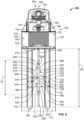
- Figs. 7 and 8 illustrate one non-limiting example of the clamping assembly 204 of the material handling vehicle 100 in a first state.
- the clamping assembly 204 can comprise a third horizontal post 252 and a clamping bar 254 positioned above the third horizontal post 252.
- the third horizontal post 252 can be substantially parallel with the first or second horizontal posts 220, 222, and can be secured to the second and third vertical posts 212, 214. As illustrated in Figs. 7 and 8 , the third horizontal post 252 is secured to the second vertical post 212 and the third vertical post 214.
- the clamping assembly 204 can further comprise a housing 256 and a fin 258.
- the housing 256 can be secured to the third horizontal post 252 and the second vertical post 212, and the housing 256 may be configured to cover one or more sensors.
- the fin 258 may comprise various text or decals thereon.
- the clamping assembly 204 can further comprise a plate 259 positioned between the third horizontal post 252 and the clamping bar 254, adjacent the housing 256. The plate 259 can be secured with the clamping bar 254.
- the third horizontal post 252 may be welded to and/or fastened to the second and/or third vertical posts 212, 214.
- each of the actuators 274 comprises an actuation rod 276 that may be secured to a clamping bracket 278 that is attached with the clamping bar 254.
- the actuation rods 276 of the actuators 274 can be configured to move the clamping bar 254 up and down relative to the material handling vehicle 100. Put differently, only the clamping bar 254 can move linearly while the actuation rods 276 translate.
- the actuation rods 276 are configured to linearly slide, i.e., move, within the actuators 274 between a first position, i.e., corresponding to the first state (see Figs.
- the clamping bar 254 can be substantially parallel with respect to the third horizontal post 252 and extend between the actuator assemblies 270. As illustrated in Fig. 8 , the clamping bar 254 can extend beyond the actuators 274 and the actuator brackets 272. As discussed above, the clamping bar 254 can be attached with the guide rod 264 at the center of the clamping bar 254. As illustrated in Figs. 7 and 8 , the clamping bar 254 can comprise a plurality of clamps 302 secured thereon. In some non-limiting examples, the plurality of clamps 302 may be welded onto the clamping bar 254.
- the plurality of clamps 302 may include a main clamp 304 and a plurality of auxiliary clamps 306.
- the main clamp 304 may comprise a main clamp body 310 and a plurality of main clamp wings 312 extending from the main clamp body 310 at four corners of the main clamp body 310. As illustrated in Fig. 8 , the plurality of main clamp wings 312 can extend downwardly and away from the main clamp body 310.
- each side of the main clamp body 310 of the main clamp 304 includes two main clamp wings 312 extending therefrom (see Fig. 6 ).
- the two main clamp wings 312 on each side of the main clamp body 310 diverge from one another and form a main clamping cavity 316 between the main clamp wings 312. As illustrated in Fig.
- the main clamp 304 can comprise an aperture 318 extending through the main clamp 304 and the clamping bar 254.
- the main clamp 304 can comprise 4 main clamp wings 312 thereon.
- the main clamp 304 may comprise 1, 2, 3, 4, 5, 6, 7, 8, or more main clamp wings 312 thereon.
- the angle of the main clamp wings 312, i.e., angle defined between each main clamp wing 312 and a line perpendicular to the ground (or orthogonal to the clamping bar 254, see Fig. 8 ) can be between about 20 degrees and about 40 degrees, or about 30 degrees.
- the clamping bar 254 can comprise 1, 2, 3, 4, 5, 6, 7, or more main clamps 304 and 1, 2, 3, 4, 5, 6, 7, 8, 9, 10, or more auxiliary clamps 306. As illustrated in Figs. 7 and 8 , the clamping bar 254 is illustrated in the first state. As discussed above, the clamping bar 254 is configured to linearly move between the first state and a second state (see Fig. 9 ). As noted herein, each of the plurality of auxiliary clamps 306 can comprise two auxiliary clamp wings 332. However, in some non-limiting examples, each of the plurality of auxiliary clamps 306 may comprise 1, 2, 3, 4, 5, 6, 7, 8 or more auxiliary clamp wings 332.
- the clamping bar length CL can be between about 10 percent and about 90 percent of the platform length PL, or between about 20 percent and about 80 percent of the platform length PL, or between about 40 percent and about 75 percent of the platform length PL, or between about 50 percent and about 60 percent of the platform length PL, or between about 55 percent and about 60 percent of the platform length PL, or about 58 percent of the platform length PL.
- Figs. 10 and 11 illustrate the material handling vehicle 100 with a plurality of carts 400 on the platform 170.
- the material handling vehicle 100 can be configured to move and/or transfer the plurality of carts 400 from one location to another. Therefore, the plurality of carts 400 can be loaded on the material handling vehicle 100, filled, and subsequently unloaded therefrom.
- each of the plurality of carts 400 are positioned over one of the forks 150.
- wheels 402 of the plurality of carts 400 are positioned on opposite sides of the forks 150.
- the clamping assembly 204 can be configured to secure the plurality of carts 400 to the material handling vehicle 100.
- the plurality of clamps 302 on the clamping bar 254 are configured to engage with a frame 404 on each of the plurality of carts 400.
- the main clamp 304 is configured to contact all four of the plurality of carts 400 and secure the same within the main clamping cavities 316
- the plurality of auxiliary clamps 306 are each configured to contact two of the plurality of carts 400 and secure the same within the auxiliary clamping cavities 334.
- each of the main clamp wings 312 of the main clamp 304 holds the frame 404 of two of the plurality of carts 400
- each of the auxiliary clamp wings 332 holds the frame 404 of one of the plurality of carts 400.
- portions of the frames 404 of the plurality of carts 400 can be positioned within the main clamping cavities 316 and the auxiliary clamping cavities 334.
- the material handling vehicle 100 is illustrated with four carts 400 thereon. However, it is contemplated that the material handling vehicle 100 can carry any number of carts 400 thereon.
- the material handling vehicle 100 can hold and/or carry 1, 2, 3, 4, 5, 6, 7, 8, 9, or more carts 400.
- the plurality of carts 400 may not be in contact with the main clamp 304 or the plurality of auxiliary clamps 306. Instead, portions of the plurality of carts 400 may be positioned inside of the main clamping cavities 316 and the auxiliary clamping cavities 334.
- the clamping bar 254 can more quickly clamp the plurality of carts 400 than if the clamping bar 254 is in the second state, i.e., the clamping bar 254 is further away from the uppermost portion 406 of the frame 404 of the plurality of carts 400 when the clamping bar 254 is in the second state than when it is in the third state.
- the clamping assembly 204 may not define the third state.
- the second state may not define a maximum limit that the actuation rods 276 of the actuators 274 can move the clamping bar 254.
- the second state may define the same state as the third state, i.e., the length L 2 of the second state is equal to the length of the third state.
- control unit 502 can communicate via wireless communication with one or more material handling vehicles 100 through a transceiver 518.
- the communication may occur through one or more of any desired combination of wireless communication mechanisms and any desired network topology (or topologies when multiple communication mechanisms are utilized).
- Exemplary wireless communication networks include a 5G networks, a BLLTETOOTH module, and/or a Wi-Fi transceiver, among others, including the Internet, cellular, satellite, microwave, and radio frequency, for providing data communication between material handling vehicles 100. It is to be understood that, while only one material handling vehicle control system 500 is illustrated in detail in Fig. 12 , each of the material handling vehicles 100 would include a substantially identical control system.
- the control unit 502 on the material handling vehicle 100 may be in communication with third party system, e.g. , a warehouse management system (WMS).
- WMS warehouse management system
- the control unit 502 can also be in communication with one or more operator indicators 520, which may prompt visual, auditory, and/or tactile indications if certain conditions are determined, as will be describe herein.
- one or more light sources on the material handling vehicle 100 or indications on a vehicle display can provide a visual indication.
- a vehicle horn and/or a speaker may provide an audible indication.
- a tactile or haptic indication can be provided as a vibration to the operator through the control handle 120, or any other portion of the material handling vehicle 100 that can be in contact with the operator.
- the control unit 502 can be in communication with an operator sensor 522.
- the control unit 502 can also be in communication with a clamping position sensor 524 and a current sensor 526.
- the clamping position sensor 524 may be configured to determine the height of the clamping assembly 204, i.e., the height of the clamping bar 254 relative to the third horizontal post 252. Put differently, the clamping position sensor 524 may be configured to determine the state, i.e., first state, second state, or third state, that the clamping bar 254 is in.
- the clamping position sensor 524 may be positioned within or near the actuator assemblies 270 and measure the stroke length of the actuation rods 276 of the actuators 274.
- the current sensor 526 may be configured to detect the force being used on the plurality of carts 400 while the clamping bar 254 is moving from the second state to the first state and/or while the plurality of carts 400 are being lifted by the platform 170.
- the current sensor 526 can be used with the actuators 274 of the actuator assemblies 270 to determine the force being used by the plurality of clamps 302 on the plurality of carts 400.
- the current sensor 526 can also be used with the actuators and/or lift cylinders that move the forks 150 and platform 170.
- the current sensor 526 can comprise one or more resistors that place an upper limit on an amount of current being drawn through the current sensor 526.
- control unit 502 can be configured to control the operation of the material handling vehicle 100.
- the control unit 502 can communicate with the various systems and sensors outlined above via a Controller Area Network (CAN) bus network or another form of wired or wireless communication. It is contemplated that the control unit 502 can be in communication with other portions of the material handling vehicle 100 in any conventional wireless or wired way.
- the control unit 502 can be a programmable logic controller (PLC).
- the clamping bar 254 can automatically move down and secure the plurality of carts 400 to the platform via the plurality of clamps 302, in step 606, after the operator sensor 522 has determined that the operator is in the operator compartment 112 in step 604. Therefore, the operator does not need to initiate any command to have the clamping bar 254 secure to the plurality of carts 400.
- the operator may manually press a button to indicate to the control unit 502 that the loading step has been finished.
- the material handling vehicle 100 can move in step 610.
- the operator can move the material handling vehicle 100 to its desired location(s).
- the material handling vehicle 100 may be configured to move to various locations while the plurality of carts 400 are loaded onto the platform 170.
- the plurality of carts 400 can be loaded onto the material handling vehicle 100 in an empty state, similar to Fig. 10 . Then, the material handling vehicle 100 may move to multiple locations throughout the warehouse, for example, to fill the plurality of carts 400.
- the process 600 includes engaging an unloading step.
- the unloading step may be engaged by the operator pressing a button or initiating a specific task on the vehicle console 122 or control handle 120.
- the operator may press a button on the vehicle console 122 or the control handle 120 to engage the unloading step.
- the platform 170 can move from the up position to the down position in step 614 and the clamping bar 254 can move from the first state to the second state in step 616.
- the platform 170 and the clamping bar 254 can move at the same time once the operator has engaged the unloading step. Therefore, once the operator engages the unloading step, the material handling vehicle 100 will automatically lower the platform 170 and raise the clamping bar 254 thereafter.
- the process 600 can assist the operator during loading and unloading of the plurality of carts 400.
- the material handling vehicle 100 and the control unit 502 can help to reduce the number of steps required by the operator. For example, as discussed above, once the plurality of carts 400 are loaded onto the platform 170, the material handling vehicle 100 can automatically begin lowering the clamping bar 254 and raising the platform 170 once the operator sensor 522 has determined that the operator is in the operator compartment 112. This process 600 can reduce the loading and unloading time. In one non-limiting example, the operator steps onto the mat 142 and the clamping bar 254 will automatically lower and the forks 150 and the platform 170 will rise thereafter.
- the operator can press a single button or indicate a single condition and the platform 170 will then lower and the clamping bar 254 will raise.
- the material handling vehicle 100 can allow more loading and unloading cycles of the carts 400.
- the current sensor 526 allows the control unit 502 (and the operator) to assess if the carts 400 are properly configured on the platform 170.
- the order of execution of the blocks may be rearranged, changed, eliminated, and/or combined to perform the process 700.
- the process 700 outlines the steps for loading and unloading the plurality of carts 400 onto the platform 170 of the material handling vehicle 100.
- Figs. 14A and 14B illustrate a single flowchart. However, due to the size of the flowchart, the flowchart has been broken up between Figs. 14A and 14B in order for the text and processes to be clear.
- the operator may turn on the material handling vehicle 100.
- the operator may use a key to turn on the material handling vehicle 100.
- the material handling vehicle 100 may be turned on in any conventional way, i.e., push button, ignition switch, remote start, etc. Once the material handling vehicle 100 is turned on, the process 700 can begin.
- the control unit 502 can detect if the platform 170 (and thus the forks 150) is in the up position, i.e., lift limit.
- the lifting sensor 516 can communicate with the control unit 502 to determine the position of the platform 170. If the platform 170 is in the up position, i.e., the limit has been detected, the process 700 will continue to perform normally. In other words, the material handling vehicle 100 can move around while the platform 170 is in the up position. If the platform 170 is not in the up position, i.e., the truck lift limit is not detected, the process 700 can proceed to step 706 where the control unit 502 can disable the material handling vehicle 100 from driving.
- step 706 the material handling vehicle 100 will not be able to move until the lifting sensor 516 has determined that the platform 170 is in the up position, i.e., the truck lift limit is detected.
- the control unit 502 is continuously monitoring to see if the platform 170 is in the up position. Therefore, step 706 may be implemented at any time throughout the process 700.
- the process 700 will continue to loop until the operator has stepped on the mat 142 in the operator compartment 112. While the operator is on the mat 142, the clamping bar 254 will continue to move from the second or third state to the first state. However, while the clamping bar 254 is moving, the control unit 502 may continually monitor to see if the operator is still on the mat 142 in step 714. If the operator moves off of the mat 142 while the clamping bar 254 is lowering, the control unit 502 may stop the movement of the clamping bar 254 and the process 700 can return to the top of the flowchart in Fig. 14A . In some non-limiting examples, the clamping bar 254 may move back to the third or second state if the operator moves off the mat 142 during movement of the clamping bar 254.
- the process 700 may continue to step 716 to detect if the current sensor 526 has detected a current over the limit.
- the current sensor 526 can be used to detect the amount of current running through the actuators 274. If a higher-than-normal force is required by the actuators 274, a higher current will be detected by the current sensor 526. If at step 716 the current is higher than the limit, the process 700 can proceed to step 718 and initiate the operator indicator 520.
- the operator indicator 520 may include an audible response such as the honking of the horn on the material handling vehicle 100. The operator indicator 520 can inform the operator that the current is over the limit in the current sensor 526.
- the process 700 may continue to step 712 and continue to move the clamping bar 254 down to the first state. If the clamping bar 254 has reached the first state, i.e., lower limit has been reached, the process 700 can continue to step 722.
- the process 700 includes lifting the platform 170 (via the forks 150) from the down position to the up position. As the platform 170 rises, the process 700 may continue to step 724 where the control unit 502 again monitors if the operator is still on the mat 142 in the operator compartment 112. As discussed above, the operator sensor 522 can communicate with the control unit 502 to determine if the operator is still on the mat 142. If the operator is not on the mat 142 in step 724, the process 700 can move back to the top of Fig. 14A and the platform 170 can stop rising.
- the platform 170 and/or the clamping bar 254 may stop at their current position until the operator steps back onto the mat 142. In some non-limiting examples, at step 724, if the operator is not on the mat 142, the platform 170 may move back to the down position and the clamping bar 254 may move up to the second or third state. Therefore, as noted herein, the operator may need to be on the mat 142 while the clamping bar 254 and the platform 170 move.
- control unit 502 can stop the lifting/lowering of the clamping bar 254 and the platform 170.
- the material handling vehicle 100 may move around the warehouse filling the carts 400, for example, until it has reached its unloading zone. While the material handling vehicle 100 continues to perform its tasks, the process 700 can continuously monitor, at step 730, to see if the lower forks button has been pressed. As noted herein, the lower forks button may engage the unloading step. If the lower forks button has been pressed, the process 700 can proceed to step 732 to determine if the platform 170 or the clamping bar 254 are currently being moved. If the platform 170 or the clamping bar 254 are being moved, the process 700 returns to the top of the flowchart until a specific situation is activated.
- step 732 If, at step 732, it is determined that the platform 170 and the clamping bar 254 are not moving, the process 700 can simultaneously proceed to step 734 and step 736. As noted herein, after step 718, the process can also proceed to steps 734 and steps 736 once the horn, i.e., operator indicator 520, has been sounded.
- the control unit 502 can start a timer t1 and then proceed to step 738 to lower the platform 170 (via the forks 150).
- the process 700 can proceed to step 740 were the control unit 502 determines if a certain time period, e.g., 5 seconds, has passed since the timer t1 has started.
- Step 740 allows enough time for the platform 170 to completely lower from the up position to the down position. In some non-liming examples, it may take 1, 2, 3, 4, 5, or 6 seconds for the platform 170 to lower to the down position. If the timer t1 has reached 5 seconds, the process 700 can proceed to the top of the flowchart in Fig. 14A .
- step 742 is determining if the operator has stepped onto the mat 142 within the operator compartment 112. As noted herein, step 742 requires the operator to step off of the mat 142 and then step back to the mat 142 to trigger the "Yes" condition in step 742. The operator can stand on the mat 142 before and while the clamping bar 254 rises and the platform 170 lowers. However, if the operator steps off the mat 142, after pressing the lower forks button, and then steps on the mat 142 at step 742, the "Yes" condition in step 742 may be activated.
- the process 700 includes releasing the clamping bar 254.
- the process 700 includes moving the clamping bar 254 from the first state to the second state to unclamp the plurality of carts 400.
- the clamping bar 254 is configured to move while the platform 170 moves in the unloading step.
- the platform 170 may be lowered to the down position before the clamping bar 254 moves from the first state to the second state.
- the current sensor 526 can be in communication with the control unit 502 to determine if there is a greater than normal force required to move the platform 170 and/or the clamping bar 254. If the current in step 746 is greater than the current limit, the process 700 will stop movement of the platform 170 and/or the clamping bar 254 and proceed to the top of the flowchart in Fig. 14A . If the current in step 746 is not greater than the current limit, the process 700 will proceed to step 748. In some non-limiting examples, if the current hits the current limit, the clamping bar 254 may move back down to the first state.
- the current sensor 526 can determine if the current from the actuators 274 is zero. As noted herein, once the actuators 274 have moved the clamping bar 254 to the second state, an internal limit switch in each of the actuators 274 can disconnect the actuators 274 from the circuit and allow there to be no current drawn by the actuators 274. Therefore, if there is still a current at step 748, then the clamping bar 254 has not yet reached the second state. As such, if the current in step 748 is not zero, the process 700 can proceed to step 736 to further raise the clamping bar 254 to the second state. If the current is at zero in step 748, the process 700 can proceed to step 750 to lower the clamping bar 254 to the third state.
- step 752 assists in identifying when the clamping bar 254 has reached the third state. If the clamping bar 254 has not reached the third state, the process 700 can continue to step 750 until the clamping position sensor 524 has determined that the clamping bar 254 has reached the third state, i.e., the upper limit detected. After the clamping bar 254 has reached the third state, the process 700 can proceed to the beginning, i.e., the top of the flow chart.
- the top of the flow chart refers to a state in which the process is waiting for a condition from step 704, step 710, or step 730 to begin. Therefore, the control unit 502 can be constantly monitoring for step 704, step 710, or step 730 to begin, i.e., initiate. In some non-limiting examples, the material handling vehicle 100 can move around while the process is waiting for one of the conditions from steps 704, 710, or 730 to begin. As further noted herein, the entire process 700 can stop or end if the key is removed from the material handling vehicle 100.
- the present disclosure provides distinct advantages, such as advantageously assisting the operator during the unloading and loading stages.
- the material handling vehicle 100 can automatically start lowering the clamping bar 254 and raising the platform 170 once the operator steps onto the mat 142 of the operator compartment 112.
- the material handling vehicle 100 can quickly lower the platform 170 and raise the clamping bar 254 once the operator has engaged the unloading step, e.g. , pressed the lower forks button. Therefore, the present disclosure provides systems and methods for minimizing the steps needed for the operator to load and unload the material handling vehicle 100.
Landscapes
- Engineering & Computer Science (AREA)
- Transportation (AREA)
- Structural Engineering (AREA)
- Mechanical Engineering (AREA)
- Civil Engineering (AREA)
- Life Sciences & Earth Sciences (AREA)
- Geology (AREA)
- Chemical & Material Sciences (AREA)
- Combustion & Propulsion (AREA)
- Forklifts And Lifting Vehicles (AREA)
Priority Applications (1)
| Application Number | Priority Date | Filing Date | Title |
|---|---|---|---|
| EP25211516.7A EP4667411A2 (de) | 2022-06-17 | 2023-06-16 | Systeme und verfahren für ein materialhandhabungsfahrzeug |
Applications Claiming Priority (1)
| Application Number | Priority Date | Filing Date | Title |
|---|---|---|---|
| US202263353451P | 2022-06-17 | 2022-06-17 |
Related Child Applications (1)
| Application Number | Title | Priority Date | Filing Date |
|---|---|---|---|
| EP25211516.7A Division EP4667411A2 (de) | 2022-06-17 | 2023-06-16 | Systeme und verfahren für ein materialhandhabungsfahrzeug |
Publications (3)
| Publication Number | Publication Date |
|---|---|
| EP4292901A1 true EP4292901A1 (de) | 2023-12-20 |
| EP4292901C0 EP4292901C0 (de) | 2025-10-29 |
| EP4292901B1 EP4292901B1 (de) | 2025-10-29 |
Family
ID=86862107
Family Applications (2)
| Application Number | Title | Priority Date | Filing Date |
|---|---|---|---|
| EP23179653.3A Active EP4292901B1 (de) | 2022-06-17 | 2023-06-16 | Verfahren für ein materialhandhabungsfahrzeug |
| EP25211516.7A Pending EP4667411A2 (de) | 2022-06-17 | 2023-06-16 | Systeme und verfahren für ein materialhandhabungsfahrzeug |
Family Applications After (1)
| Application Number | Title | Priority Date | Filing Date |
|---|---|---|---|
| EP25211516.7A Pending EP4667411A2 (de) | 2022-06-17 | 2023-06-16 | Systeme und verfahren für ein materialhandhabungsfahrzeug |
Country Status (6)
| Country | Link |
|---|---|
| US (1) | US20230406683A1 (de) |
| EP (2) | EP4292901B1 (de) |
| CN (1) | CN117246952A (de) |
| AU (1) | AU2023203782A1 (de) |
| CA (1) | CA3203724A1 (de) |
| MX (1) | MX2023007269A (de) |
Families Citing this family (3)
| Publication number | Priority date | Publication date | Assignee | Title |
|---|---|---|---|---|
| CN112298880A (zh) * | 2020-06-30 | 2021-02-02 | 北京京东乾石科技有限公司 | 仓库穿梭车 |
| AU2025202103A1 (en) * | 2024-03-29 | 2025-10-16 | The Raymond Corporation | Clamping assembly for a material handling vehicle |
| CN118976718B (zh) * | 2024-10-22 | 2025-04-11 | 常州中信照明电器有限公司 | Y型输送机灯具品类分类装置 |
Citations (3)
| Publication number | Priority date | Publication date | Assignee | Title |
|---|---|---|---|---|
| US20130189046A1 (en) * | 2011-07-20 | 2013-07-25 | Alan William Bartels | Cart carrier with biased clamping device |
| US8894037B1 (en) * | 2011-07-20 | 2014-11-25 | Jeffrey L. Brauer | Lift truck platform apparatus and methods for transporting rolling racks |
| US20170313335A1 (en) * | 2016-04-29 | 2017-11-02 | Crown Equipment Corporation | Pallet truck cart transportation device |
Family Cites Families (4)
| Publication number | Priority date | Publication date | Assignee | Title |
|---|---|---|---|---|
| US5340268A (en) * | 1992-02-20 | 1994-08-23 | Dowty Alvis E | Article handling mechanism for attachment to warehouse trucks |
| DE102004027445B4 (de) * | 2004-06-04 | 2008-01-31 | Jungheinrich Aktiengesellschaft | Vorrichtung zum Halten einer Last auf einem Lasttragmittel eines Flurförderzeugs |
| US8272824B1 (en) * | 2007-08-21 | 2012-09-25 | Lloyd Pete Putney | Apparatus for installing poles for pole buildings |
| US9764675B1 (en) * | 2014-09-30 | 2017-09-19 | Daniel Theobald | Item manipulating and gathering method |
-
2023
- 2023-06-15 US US18/210,325 patent/US20230406683A1/en active Pending
- 2023-06-16 MX MX2023007269A patent/MX2023007269A/es unknown
- 2023-06-16 CA CA3203724A patent/CA3203724A1/en active Pending
- 2023-06-16 EP EP23179653.3A patent/EP4292901B1/de active Active
- 2023-06-16 EP EP25211516.7A patent/EP4667411A2/de active Pending
- 2023-06-16 AU AU2023203782A patent/AU2023203782A1/en active Pending
- 2023-06-19 CN CN202310729360.4A patent/CN117246952A/zh active Pending
Patent Citations (3)
| Publication number | Priority date | Publication date | Assignee | Title |
|---|---|---|---|---|
| US20130189046A1 (en) * | 2011-07-20 | 2013-07-25 | Alan William Bartels | Cart carrier with biased clamping device |
| US8894037B1 (en) * | 2011-07-20 | 2014-11-25 | Jeffrey L. Brauer | Lift truck platform apparatus and methods for transporting rolling racks |
| US20170313335A1 (en) * | 2016-04-29 | 2017-11-02 | Crown Equipment Corporation | Pallet truck cart transportation device |
Also Published As
| Publication number | Publication date |
|---|---|
| MX2023007269A (es) | 2023-12-18 |
| EP4667411A2 (de) | 2025-12-24 |
| AU2023203782A1 (en) | 2024-01-18 |
| EP4292901C0 (de) | 2025-10-29 |
| CA3203724A1 (en) | 2023-12-17 |
| EP4292901B1 (de) | 2025-10-29 |
| US20230406683A1 (en) | 2023-12-21 |
| CN117246952A (zh) | 2023-12-19 |
Similar Documents
| Publication | Publication Date | Title |
|---|---|---|
| EP4292901A1 (de) | Verfahren für ein materialhandhabungsfahrzeug | |
| JP2008536779A (ja) | コンテナを吊り上げ、取り扱い及び輸送する装置 | |
| CN106604886A (zh) | 具有光学货物感测结构的叉车 | |
| EP3339238B1 (de) | Systeme und verfahren zur bestimmung eines warenregals, für ein materialhandhabungsfahrzeug | |
| US6733226B1 (en) | Vehicle moving apparatus | |
| EP4624305A1 (de) | Klemmvorrichtung für materialhandhabungsfahrzeug | |
| CA3269239A1 (en) | Clamping assembly for a material handling vehicle | |
| EP0374104B1 (de) | Vorrichtung zum automatischen Parken von Fahrzeugen mit Mitteln zum Einstellen bzw. automatischen Abholen von Fahrzeugen | |
| HK40101352A (zh) | 用於物料搬运车辆的系统和方法 | |
| JP5900987B2 (ja) | 荷役車両 | |
| HK40126776A (zh) | 用於物料搬运车辆的夹持组件 | |
| JP7095553B2 (ja) | フォークリフトの遠隔操作システム | |
| JP4214813B2 (ja) | 無人フォークリフト | |
| JP2003312995A (ja) | フォークリフト | |
| JPH054719A (ja) | 運搬車 | |
| JP2017186112A (ja) | フォークリフトの制御方法 | |
| JP6984462B2 (ja) | フォークリフト | |
| JP2006298638A (ja) | フォークリフト | |
| JP3669902B2 (ja) | 荷役車両 | |
| JP3669901B2 (ja) | 荷役車両 | |
| JP3650024B2 (ja) | フォークリフト | |
| JP5999737B2 (ja) | 荷役車両 | |
| JP2001354399A (ja) | リーチ型フォークリフト | |
| JP3578331B2 (ja) | 荷役車両 | |
| JP3949004B2 (ja) | ピッキングトラック |
Legal Events
| Date | Code | Title | Description |
|---|---|---|---|
| PUAI | Public reference made under article 153(3) epc to a published international application that has entered the european phase |
Free format text: ORIGINAL CODE: 0009012 |
|
| STAA | Information on the status of an ep patent application or granted ep patent |
Free format text: STATUS: THE APPLICATION HAS BEEN PUBLISHED |
|
| AK | Designated contracting states |
Kind code of ref document: A1 Designated state(s): AL AT BE BG CH CY CZ DE DK EE ES FI FR GB GR HR HU IE IS IT LI LT LU LV MC ME MK MT NL NO PL PT RO RS SE SI SK SM TR |
|
| STAA | Information on the status of an ep patent application or granted ep patent |
Free format text: STATUS: REQUEST FOR EXAMINATION WAS MADE |
|
| 17P | Request for examination filed |
Effective date: 20240612 |
|
| RBV | Designated contracting states (corrected) |
Designated state(s): AL AT BE BG CH CY CZ DE DK EE ES FI FR GB GR HR HU IE IS IT LI LT LU LV MC ME MK MT NL NO PL PT RO RS SE SI SK SM TR |
|
| GRAP | Despatch of communication of intention to grant a patent |
Free format text: ORIGINAL CODE: EPIDOSNIGR1 |
|
| STAA | Information on the status of an ep patent application or granted ep patent |
Free format text: STATUS: GRANT OF PATENT IS INTENDED |
|
| RIC1 | Information provided on ipc code assigned before grant |
Ipc: B66F 9/18 20060101ALI20250508BHEP Ipc: B66F 9/12 20060101ALI20250508BHEP Ipc: B62B 3/10 20060101ALI20250508BHEP Ipc: B62B 3/06 20060101ALI20250508BHEP Ipc: B62B 3/04 20060101AFI20250508BHEP |
|
| INTG | Intention to grant announced |
Effective date: 20250523 |
|
| GRAS | Grant fee paid |
Free format text: ORIGINAL CODE: EPIDOSNIGR3 |
|
| GRAA | (expected) grant |
Free format text: ORIGINAL CODE: 0009210 |
|
| STAA | Information on the status of an ep patent application or granted ep patent |
Free format text: STATUS: THE PATENT HAS BEEN GRANTED |
|
| AK | Designated contracting states |
Kind code of ref document: B1 Designated state(s): AL AT BE BG CH CY CZ DE DK EE ES FI FR GB GR HR HU IE IS IT LI LT LU LV MC ME MK MT NL NO PL PT RO RS SE SI SK SM TR |
|
| REG | Reference to a national code |
Ref country code: CH Ref legal event code: F10 Free format text: ST27 STATUS EVENT CODE: U-0-0-F10-F00 (AS PROVIDED BY THE NATIONAL OFFICE) Effective date: 20251029 Ref country code: GB Ref legal event code: FG4D |
|
| REG | Reference to a national code |
Ref country code: IE Ref legal event code: FG4D |
|
| REG | Reference to a national code |
Ref country code: DE Ref legal event code: R096 Ref document number: 602023007931 Country of ref document: DE |
|
| U01 | Request for unitary effect filed |
Effective date: 20251128 |
|
| U07 | Unitary effect registered |
Designated state(s): AT BE BG DE DK EE FI FR IT LT LU LV MT NL PT RO SE SI Effective date: 20251204 |