EP4290147A1 - Klimaanlage - Google Patents
Klimaanlage Download PDFInfo
- Publication number
- EP4290147A1 EP4290147A1 EP21924805.1A EP21924805A EP4290147A1 EP 4290147 A1 EP4290147 A1 EP 4290147A1 EP 21924805 A EP21924805 A EP 21924805A EP 4290147 A1 EP4290147 A1 EP 4290147A1
- Authority
- EP
- European Patent Office
- Prior art keywords
- air
- refrigerant
- chamber
- refrigerant detection
- fan
- Prior art date
- Legal status (The legal status is an assumption and is not a legal conclusion. Google has not performed a legal analysis and makes no representation as to the accuracy of the status listed.)
- Withdrawn
Links
Images

Classifications
-
- F—MECHANICAL ENGINEERING; LIGHTING; HEATING; WEAPONS; BLASTING
- F24—HEATING; RANGES; VENTILATING
- F24F—AIR-CONDITIONING; AIR-HUMIDIFICATION; VENTILATION; USE OF AIR CURRENTS FOR SCREENING
- F24F11/00—Control or safety arrangements
- F24F11/30—Control or safety arrangements for purposes related to the operation of the system, e.g. for safety or monitoring
- F24F11/32—Responding to malfunctions or emergencies
- F24F11/36—Responding to malfunctions or emergencies to leakage of heat-exchange fluid
-
- F—MECHANICAL ENGINEERING; LIGHTING; HEATING; WEAPONS; BLASTING
- F24—HEATING; RANGES; VENTILATING
- F24F—AIR-CONDITIONING; AIR-HUMIDIFICATION; VENTILATION; USE OF AIR CURRENTS FOR SCREENING
- F24F1/00—Room units for air-conditioning, e.g. separate or self-contained units or units receiving primary air from a central station
- F24F1/0007—Indoor units, e.g. fan coil units
Definitions
- Patent Literature 1 discloses a refrigerant detection device that includes a refrigerant detection air passage having both ends connected to a main air passage extending from a suction port to an blowoff port of an indoor unit of an air-conditioning apparatus, and a refrigerant detection sensor that detects a refrigerant inside the refrigerant detection air passage, in which the refrigerant detection air passage allows an air-sending port side and an intake port side of an air blower to communicate with each other, the air blower being provided in the main air passage and being configured to send air from the suction port to the blowoff port, and the air is guided to the outside of the main air passage in a housing of the indoor unit of the air-conditioning apparatus, so that refrigerant leakage can be detected.
- Patent Literature 1 WO2018/198165
- the present disclosure provides an air conditioner capable of detecting refrigerant leakage on a heat exchanger chamber side with high accuracy.
- the present disclosure is an air conditioner that includes: a housing including a suction port through which air flows in and a blowoff port through which the air flows out; a partitioning wall that partitions an inside of the housing into an air-sending chamber and a heat exchanger chamber having a heat exchanger; a refrigerant detection duct that provides communication between an inside of the air-sending chamber and an inside of the heat exchanger chamber; and a refrigerant detection sensor that detects a refrigerant inside the refrigerant detection duct, in which a scroll casing in which a fan opening part is formed, a sirocco fan housed inside the scroll casing, and an air-sending passage that discharges the air sucked through the fan opening part by rotation of the sirocco fan toward the heat exchanger chamber are provided, an end of the refrigerant detection duct is an air-sending chamber-side opening disposed inside the air-sending chamber, another end of the refrigerant detection duct is a heat exchanger chamber-side opening disposed inside
- refrigerant leakage on a heat exchanger chamber side can be detected with high accuracy.
- a technique had been known in a form of a refrigerant detection device, in which a refrigerant detection air passage having both ends connected to a main air passage extending from a suction port to an blowoff port of an indoor unit of an air-conditioning apparatus, and a refrigerant detection sensor that detects a refrigerant inside the refrigerant detection air passage are provided, and the refrigerant detection air passage allows an air-sending port side and an intake port side of an air blower to communicate with each other, the air blower being provided in the main air passage and being configured to send air from the suction port to the blowoff port.
- an inlet of the refrigerant detection air passage is disposed in the blowoff port of the indoor unit and an outlet is disposed in a suction port of the indoor unit.
- the present disclosure provides an air conditioner capable of detecting refrigerant leakage on the heat exchanger chamber side with high accuracy.
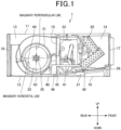
- Embodiment 1 will be described with reference to Figure 1 and Figure 2 .
- Figure 1 is a cross-sectional side view of an air conditioner of Embodiment 1.
- Figure 2 is a plan view of the air conditioner of Embodiment 1.
- an air conditioner 1 of the present embodiment includes a box-shaped housing 10.
- the housing 10 includes a top plate 11 and a bottom plate 12.
- the left side of the housing 10 in Figure 1 is an air-sending chamber 13 and the right side of the housing 10 in Figure 1 is a heat exchanger chamber 14 that houses a heat exchanger 20.
- the air-sending chamber 13 and the heat exchanger chamber 14 are partitioned by a partitioning wall 15.
- a rear of the air-sending chamber 13 is provided with a suction port 16 to take in indoor air, and an inside of the air-sending chamber 13 is provided with a plurality of (three in the present embodiment) scroll casings 31, each scroll casing 31 housing a sirocco fan 30.
- a forward side relative to the heat exchanger 20 of the heat exchanger chamber 14 is provided with a blowoff port 17.
- the scroll casing 31 includes a fan opening part 32 that is formed at each of both ends of the scroll casing 31 and sucks air flown in through the suction port 16 by rotation of the sirocco fan 30, and an air-sending passage 33 that discharges the air sucked through the fan opening part 32 toward the heat exchanger chamber 14.
- An electric motor 34 is provided between the scroll casings 31.
- the electric motor 34 is coupled to a rotating shaft 35 of the sirocco fan 30 and rotationally drives the sirocco fan 30.
- a drain pan 21 is disposed in a lower portion of the heat exchanger 20 housed in the heat exchanger chamber 14 in Figure 1 .
- the heat exchanger chamber 14 is provided with a partitioning plate 25 that partitions between a heat exchanging region 22 of the heat exchanger 20 and a header region 23, to which a refrigerant pipe 24 is connected, at each of both ends of the heat exchanger 20.
- the heat exchanger chamber 14 is provided with a refrigerant suction duct 41.
- the refrigerant suction duct 41 extends in the width direction of the heat exchanger chamber 14, and a heat exchanger chamber-side opening 42 at each of both ends of the refrigerant suction duct 41 is configured to provide communication between each partitioning plate 25 and the header region 23.
- the refrigerant suction duct 41 and the branched duct 43 form a refrigerant detection duct 40.
- the refrigerant detection duct 40 may be configured to provide communication between either the heat exchanging region 22 or the header region 23 and the air-sending chamber 13.
- the branched duct 43 extends downward near and along the partitioning wall 15, and an end portion on the air-sending chamber 13 side of the branched duct 43 extends upward from a lower side of the sirocco fan 30, with an air-sending chamber-side opening 44 opened upward.
- the branched duct 43 is disposed in a region between two of the scroll casings 31 and where the electric motor 34 is not disposed. Specifically, since the position between the fan opening parts 32 of the two scroll casings 31 has a more negative pressure than a space between the scroll casings 31 and a side wall of the housing 10, the refrigerant inside the branched duct 43 is more easily discharged to the fan opening part 32.
- branched duct 43 may be disposed in a position other than the position between the scroll casings 31.
- a refrigerant detection sensor 46 that detects the refrigerant is disposed.
- the air-sending chamber-side opening 44 of the branched duct 43 is disposed in a region overlapping a semi-circular region of the fan opening part 32 on a suction port 16 side relative to an imaginary perpendicular line (denoted by a dashed line in Figure 1 ) passing the rotating shaft 35 of the sirocco fan 30 when viewed from the direction of the rotating shaft 35 of the sirocco fan 30.
- the periphery portion When the sirocco fan 30 is rotationally driven, in the fan opening part 32, the periphery portion has a more negative pressure compared to a center portion where the rotating shaft 35 is located, and therefore, the refrigerant more easily flows out through the air-sending chamber-side opening 44.
- the air-sending chamber-side opening 44 may be disposed near an end portion of the fan opening part 32 on the suction port 16 side when viewed from the direction of the rotating shaft 35 of the sirocco fan 30.
- the branched duct 43 can also play a role as a partitioning wall to prevent air collision in the sirocco fan 30.
- a space having a negative pressure in a lower region of the fan opening part 32 can be broadened, so that the inflow of the refrigerant from the refrigerant detection duct 40 can be prompted and suction of the air of the main stream through the fan opening part 32 can also be prompted.
- the air-sending chamber-side opening 44 may be disposed in a region overlapping a region on a top plate 11 side of the housing 10 relative to the imaginary horizontal line passing the rotating shaft 35 of the sirocco fan 30.
- the air-sending chamber-side opening 44 is most preferably disposed in a position that is in the periphery portion of the fan opening part 32 and that is slightly closer to the top plate 11 side relative to the end portion on the suction port 16 side of the fan opening part 32.
- the direction of the refrigerant flow in the air-sending chamber-side opening 44 and the rotating direction of the sirocco fan 30 can be made substantially consistent by disposing the air-sending chamber-side opening 44 facing upward in the periphery portion of the fan opening part 32, and in this manner, the leaked refrigerant from the branched duct 43 can be smoothly sucked into the fan opening part 32.
- the heat exchanger chamber-side opening 42 of the refrigerant detection duct 40 is disposed in a position at the highest of a bank portion 26 of the drain pan 21. In this manner, the inflow of the drain water accumulated in the drain pan 21 through the heat exchanger chamber-side opening 42 into the refrigerant detection duct 40 can be suppressed.
- the heat exchanger chamber-side opening 42 is disposed in a position lower than a lower edge of the blowoff port 17 of the housing 10. Since the specific gravity of a refrigerant R32 is heavier than air, the leaked refrigerant is accumulated near the bottom plate, when the refrigerant leakage occurs. Further, near the bottom plate of the heat exchanger chamber 14, the air blown out through the blowoff port 17 does not flow and the air stagnates. Therefore, with the heat exchanger chamber-side opening 42 disposed in a position lower than the lower edge of the blowoff port 17 of the housing 10, the effect of the air blown out through the blowoff port 17 is mitigated, so that the leaked refrigerant can be made to more easily flow into the heat exchanger chamber-side opening 42.
- the air is sucked through the suction port 16 by driving the motor 34 to rotationally drive the sirocco fan 30, and the air flows into the scroll casing 31 from the direction of the rotating shaft 35 through the fan opening part 32 and is blown out from the air-sending passage 33 to the heat exchanger 20, and the conditioned air after being heat-exchanged in the heat exchanger 20 is discharged through the blowoff port 17.
- the refrigerant can be detected by means of the refrigerant detection sensor 46 housed in a housing portion midway in the branched duct 43.
- the heat exchanger chamber-side opening 42 is disposed in a position lower than the blowoff port 17, when the sirocco fan 30 is in a stopped state and in a case where the refrigerant leakage occurs, the refrigerant is heavier than air and thus enters the heat exchanger chamber-side opening 42 before leaking through the blowoff port 17, and is then accumulated in the refrigerant trap 45.
- the leaked refrigerant can be sent to the refrigerant detection sensor 46, so that the refrigerant leakage can be detected.
- the refrigerant detection duct 40 that opens in the heat exchanger chamber 14 and the air-sending chamber 13 at respective ends, and the refrigerant detection sensor 46 that detects the refrigerant inside the refrigerant detection duct 40 are provided, and the air-sending chamber-side opening 44 of the refrigerant detection duct 40 is disposed in the region overlapping the semi-circular region of the fan opening part 32 on the suction port 16 side relative to the imaginary perpendicular line passing the rotating shaft 35 of the sirocco fan 30 when viewed from the direction of the rotating shaft 35.
- the pressure near the air-sending chamber-side opening 44 of the refrigerant detection duct 40 can be maintained at a negative pressure. Therefore, the refrigerant leakage on the heat exchanger chamber 14 side can be detected with high accuracy.
- the air-sending chamber-side opening 44 of the refrigerant detection duct 40 is disposed in the periphery portion of the fan opening part 32 when viewed from the direction of the rotating shaft 35 of the sirocco fan 30.
- the periphery portion has a more negative pressure compared to the center portion where the rotating shaft 35 is located, and therefore, the refrigerant is made to more easily flow out through the air-sending chamber-side opening 44.
- the leaked refrigerant from the refrigerant detection duct 40 can be smoothly sucked into the fan opening part 32.
- the air-sending chamber-side opening 44 of the refrigerant detection duct 40 opens toward the top plate 11 of the housing 10.
- the air-sending chamber-side opening 44 provided so as to face upward, the direction of the refrigerant flow in the air-sending chamber-side opening 44 and the rotating direction of the sirocco fan 30 can be made substantially consistent. Therefore, the leaked refrigerant from the refrigerant detection duct 40 can be smoothly sucked into the fan opening part 32.
- the air-sending chamber-side opening 44 of the refrigerant detection duct 40 is disposed in the region overlapping the region on the bottom plate 12 side of the housing 10 relative to the rotating shaft 35 of the sirocco fan 30 in the fan opening part 32.
- the refrigerant detection duct 40 can also play a role as a partitioning wall to prevent air collision in the sirocco fan 30.
- the space having a negative pressure in the lower region of the fan opening part 32 can be broadened, so that the inflow of the refrigerant from the refrigerant detection duct 40 can be prompted and suction of the air of the main stream through the fan opening part 32 can also be prompted.
- the air-sending chamber-side opening 44 of the refrigerant detection duct 40 is disposed near the end portion of the fan opening part 32 on the suction port 16 side when viewed from the direction of the rotating shaft 35 of the sirocco fan 30.
- the air-sending chamber-side opening 44 disposed near the end portion on the suction port 16 side of the fan opening part 32, the direction of the refrigerant flow in the air-sending chamber-side opening 44 and the rotating direction of the sirocco fan 30 can be made substantially consistent. Therefore, the refrigerant inside the branched duct 43 is more easily discharged to the air-sending chamber-side opening 44.
- the air-sending chamber-side opening 44 of the refrigerant detection duct 40 is disposed in the region overlapping the region on the top plate 11 side of the housing 10 relative to the rotating shaft 35 of the sirocco fan 30.
- the sirocco fan 30 includes the plurality of scroll casings 31, and the air-sending chamber-side opening 44 of the refrigerant detection duct 40 is disposed in a region between the plurality of scroll casings 31.
- the pressure near the air-sending chamber-side opening 44 can be made further negative. Therefore, the refrigerant inside the refrigerant detection duct 40 can be more easily discharged to the fan opening part 32.
- the heat exchanger chamber-side opening 42 of the refrigerant detection duct 40 is disposed in a position higher than the highest portion of the bank portion 26 of the drain pan 21 provided in the housing 10.
- the refrigerant trap 45 is formed in a midway portion of the refrigerant detection duct 40, and the refrigerant detection sensor 46 is disposed in the refrigerant trap 45.
- the sirocco fan 30 is in a stopped state, the leaked refrigerant can be accumulated in the refrigerant trap 45. Therefore, even the sirocco fan 30 is in a stopped state, the refrigerant leakage can be detected.
- the air conditioner according to the present disclosure is preferably applicable to an air conditioner in which when refrigerant leakage occurs in the heat exchanger chamber, the pressure near the air-sending chamber-side opening is maintained at a negative pressure to thus enable the leaked refrigerant to be drawn into the refrigerant detection duct so that the refrigerant leakage can be detected by the refrigerant detection sensor provided in the refrigerant detection duct.
Landscapes
- Engineering & Computer Science (AREA)
- Chemical & Material Sciences (AREA)
- Combustion & Propulsion (AREA)
- Mechanical Engineering (AREA)
- General Engineering & Computer Science (AREA)
- Air Conditioning Control Device (AREA)
- Devices For Blowing Cold Air, Devices For Blowing Warm Air, And Means For Preventing Water Condensation In Air Conditioning Units (AREA)
- Air Filters, Heat-Exchange Apparatuses, And Housings Of Air-Conditioning Units (AREA)
Applications Claiming Priority (2)
| Application Number | Priority Date | Filing Date | Title |
|---|---|---|---|
| JP2021017423A JP7422314B2 (ja) | 2021-02-05 | 2021-02-05 | 空気調和機 |
| PCT/JP2021/044486 WO2022168420A1 (ja) | 2021-02-05 | 2021-12-03 | 空気調和機 |
Publications (2)
| Publication Number | Publication Date |
|---|---|
| EP4290147A1 true EP4290147A1 (de) | 2023-12-13 |
| EP4290147A4 EP4290147A4 (de) | 2024-07-17 |
Family
ID=82741124
Family Applications (1)
| Application Number | Title | Priority Date | Filing Date |
|---|---|---|---|
| EP21924805.1A Withdrawn EP4290147A4 (de) | 2021-02-05 | 2021-12-03 | Klimaanlage |
Country Status (3)
| Country | Link |
|---|---|
| EP (1) | EP4290147A4 (de) |
| JP (1) | JP7422314B2 (de) |
| WO (1) | WO2022168420A1 (de) |
Family Cites Families (7)
| Publication number | Priority date | Publication date | Assignee | Title |
|---|---|---|---|---|
| JPH10252695A (ja) * | 1997-03-13 | 1998-09-22 | Zexel Corp | 遠心式送風機とその形状決定方法 |
| WO2013038599A1 (ja) * | 2011-09-14 | 2013-03-21 | パナソニック株式会社 | 空気調和機 |
| KR101625828B1 (ko) * | 2014-12-08 | 2016-05-31 | 주식회사 토네이도시스템즈 | 스월러팬을 구비한 배기장치 모듈 |
| WO2018198165A1 (ja) * | 2017-04-24 | 2018-11-01 | 三菱電機株式会社 | 冷媒検知装置及び空気調和装置の室内機 |
| JP7176175B2 (ja) * | 2017-06-30 | 2022-11-22 | 三菱電機株式会社 | 空気調和機 |
| DE112018006844B4 (de) * | 2018-01-12 | 2023-10-19 | Mitsubishi Electric Corporation | Klimaanlage |
| JP2021017423A (ja) | 2019-07-23 | 2021-02-15 | 株式会社Screenホールディングス | 灌流液および灌流方法 |
-
2021
- 2021-02-05 JP JP2021017423A patent/JP7422314B2/ja active Active
- 2021-12-03 WO PCT/JP2021/044486 patent/WO2022168420A1/ja not_active Ceased
- 2021-12-03 EP EP21924805.1A patent/EP4290147A4/de not_active Withdrawn
Also Published As
| Publication number | Publication date |
|---|---|
| WO2022168420A1 (ja) | 2022-08-11 |
| JP2022120497A (ja) | 2022-08-18 |
| EP4290147A4 (de) | 2024-07-17 |
| JP7422314B2 (ja) | 2024-01-26 |
Similar Documents
| Publication | Publication Date | Title |
|---|---|---|
| US10465697B2 (en) | Centrifugal fan and air conditioner having the same | |
| CN105987022B (zh) | 离心风扇及具有该离心风扇的空调机 | |
| CN109790842B (zh) | 横流式风机及包括该横流式风机的空调装置的室内机组 | |
| TW201723321A (zh) | 通風裝置 | |
| JP6388734B2 (ja) | 冷凍サイクル装置の室外機 | |
| KR20150077776A (ko) | 제습기 | |
| EP4290147A1 (de) | Klimaanlage | |
| TW200530539A (en) | Integral air conditioner | |
| CN109983282B (zh) | 空调装置的室内机组 | |
| TWI794779B (zh) | 空調裝置 | |
| JP7422312B2 (ja) | 天井埋込型室内機 | |
| CN104685218B (zh) | 螺旋桨式风扇 | |
| US12320363B2 (en) | Centrifugal air-sending device and air-conditioning apparatus | |
| WO2019087421A1 (ja) | 空気調和機の室内機 | |
| CN105805026A (zh) | 送风装置 | |
| CN112833476B (zh) | 空气调节机 | |
| JP7399156B2 (ja) | 空気調和機 | |
| CN102313319A (zh) | 空调机 | |
| ES2887855T3 (es) | Unidad interior para acondicionador de aire | |
| CN105371460B (zh) | 送风装置 | |
| JP2025159927A (ja) | 送風装置、及び空気調和装置の室内機 | |
| CN110546436B (zh) | 空调机的室内机 | |
| CN110603413A (zh) | 空调机的室内机 | |
| US20240026896A1 (en) | Centrifugal air-sending device and air-conditioning apparatus | |
| WO2021111509A1 (ja) | 送風機及び空気調和装置 |
Legal Events
| Date | Code | Title | Description |
|---|---|---|---|
| STAA | Information on the status of an ep patent application or granted ep patent |
Free format text: STATUS: THE INTERNATIONAL PUBLICATION HAS BEEN MADE |
|
| PUAI | Public reference made under article 153(3) epc to a published international application that has entered the european phase |
Free format text: ORIGINAL CODE: 0009012 |
|
| STAA | Information on the status of an ep patent application or granted ep patent |
Free format text: STATUS: REQUEST FOR EXAMINATION WAS MADE |
|
| 17P | Request for examination filed |
Effective date: 20230329 |
|
| AK | Designated contracting states |
Kind code of ref document: A1 Designated state(s): AL AT BE BG CH CY CZ DE DK EE ES FI FR GB GR HR HU IE IS IT LI LT LU LV MC MK MT NL NO PL PT RO RS SE SI SK SM TR |
|
| DAV | Request for validation of the european patent (deleted) | ||
| DAX | Request for extension of the european patent (deleted) | ||
| A4 | Supplementary search report drawn up and despatched |
Effective date: 20240614 |
|
| RIC1 | Information provided on ipc code assigned before grant |
Ipc: F24F 13/20 20060101ALI20240610BHEP Ipc: F24F 1/0007 20190101ALI20240610BHEP Ipc: F24F 11/89 20180101ALI20240610BHEP Ipc: F24F 11/36 20180101AFI20240610BHEP |
|
| STAA | Information on the status of an ep patent application or granted ep patent |
Free format text: STATUS: THE APPLICATION IS DEEMED TO BE WITHDRAWN |
|
| 18D | Application deemed to be withdrawn |
Effective date: 20250103 |