EP4290083A2 - Rouet de ventilateur constitué de deux parties aubagées connectées axialement l'une à l'autre - Google Patents
Rouet de ventilateur constitué de deux parties aubagées connectées axialement l'une à l'autre Download PDFInfo
- Publication number
- EP4290083A2 EP4290083A2 EP23198649.8A EP23198649A EP4290083A2 EP 4290083 A2 EP4290083 A2 EP 4290083A2 EP 23198649 A EP23198649 A EP 23198649A EP 4290083 A2 EP4290083 A2 EP 4290083A2
- Authority
- EP
- European Patent Office
- Prior art keywords
- impeller blades
- wheel portion
- connector
- wheel
- support ring
- Prior art date
- Legal status (The legal status is an assumption and is not a legal conclusion. Google has not performed a legal analysis and makes no representation as to the accuracy of the status listed.)
- Pending
Links
- 238000000034 method Methods 0.000 claims abstract description 27
- 238000003466 welding Methods 0.000 claims description 22
- 239000000463 material Substances 0.000 claims description 14
- 230000000295 complement effect Effects 0.000 claims description 5
- 230000008569 process Effects 0.000 claims description 5
- 238000010137 moulding (plastic) Methods 0.000 claims description 4
- 239000004033 plastic Substances 0.000 claims description 4
- 230000008878 coupling Effects 0.000 claims description 3
- 238000010168 coupling process Methods 0.000 claims description 3
- 238000005859 coupling reaction Methods 0.000 claims description 3
- 239000007789 gas Substances 0.000 description 12
- 238000002485 combustion reaction Methods 0.000 description 5
- 238000010438 heat treatment Methods 0.000 description 3
- 239000000411 inducer Substances 0.000 description 3
- 229920002292 Nylon 6 Polymers 0.000 description 2
- 230000000712 assembly Effects 0.000 description 2
- 238000000429 assembly Methods 0.000 description 2
- 238000001816 cooling Methods 0.000 description 2
- 239000000446 fuel Substances 0.000 description 2
- 239000003365 glass fiber Substances 0.000 description 2
- 238000004519 manufacturing process Methods 0.000 description 2
- 238000005057 refrigeration Methods 0.000 description 2
- RNFJDJUURJAICM-UHFFFAOYSA-N 2,2,4,4,6,6-hexaphenoxy-1,3,5-triaza-2$l^{5},4$l^{5},6$l^{5}-triphosphacyclohexa-1,3,5-triene Chemical compound N=1P(OC=2C=CC=CC=2)(OC=2C=CC=CC=2)=NP(OC=2C=CC=CC=2)(OC=2C=CC=CC=2)=NP=1(OC=1C=CC=CC=1)OC1=CC=CC=C1 RNFJDJUURJAICM-UHFFFAOYSA-N 0.000 description 1
- 229920002302 Nylon 6,6 Polymers 0.000 description 1
- 229920006088 Schulamid® Polymers 0.000 description 1
- 229920006097 Ultramide® Polymers 0.000 description 1
- 238000004378 air conditioning Methods 0.000 description 1
- 230000004075 alteration Effects 0.000 description 1
- 230000004888 barrier function Effects 0.000 description 1
- 230000003247 decreasing effect Effects 0.000 description 1
- 239000003063 flame retardant Substances 0.000 description 1
- 230000007246 mechanism Effects 0.000 description 1
- 230000004048 modification Effects 0.000 description 1
- 238000012986 modification Methods 0.000 description 1
- 229920000642 polymer Polymers 0.000 description 1
- 230000001105 regulatory effect Effects 0.000 description 1
- 238000006467 substitution reaction Methods 0.000 description 1
- 238000009423 ventilation Methods 0.000 description 1
Images


Classifications
-
- F—MECHANICAL ENGINEERING; LIGHTING; HEATING; WEAPONS; BLASTING
- F04—POSITIVE - DISPLACEMENT MACHINES FOR LIQUIDS; PUMPS FOR LIQUIDS OR ELASTIC FLUIDS
- F04D—NON-POSITIVE-DISPLACEMENT PUMPS
- F04D17/00—Radial-flow pumps, e.g. centrifugal pumps; Helico-centrifugal pumps
- F04D17/08—Centrifugal pumps
- F04D17/16—Centrifugal pumps for displacing without appreciable compression
- F04D17/162—Double suction pumps
-
- F—MECHANICAL ENGINEERING; LIGHTING; HEATING; WEAPONS; BLASTING
- F04—POSITIVE - DISPLACEMENT MACHINES FOR LIQUIDS; PUMPS FOR LIQUIDS OR ELASTIC FLUIDS
- F04D—NON-POSITIVE-DISPLACEMENT PUMPS
- F04D29/00—Details, component parts, or accessories
- F04D29/26—Rotors specially for elastic fluids
- F04D29/28—Rotors specially for elastic fluids for centrifugal or helico-centrifugal pumps for radial-flow or helico-centrifugal pumps
- F04D29/281—Rotors specially for elastic fluids for centrifugal or helico-centrifugal pumps for radial-flow or helico-centrifugal pumps for fans or blowers
-
- B—PERFORMING OPERATIONS; TRANSPORTING
- B29—WORKING OF PLASTICS; WORKING OF SUBSTANCES IN A PLASTIC STATE IN GENERAL
- B29C—SHAPING OR JOINING OF PLASTICS; SHAPING OF MATERIAL IN A PLASTIC STATE, NOT OTHERWISE PROVIDED FOR; AFTER-TREATMENT OF THE SHAPED PRODUCTS, e.g. REPAIRING
- B29C65/00—Joining or sealing of preformed parts, e.g. welding of plastics materials; Apparatus therefor
- B29C65/02—Joining or sealing of preformed parts, e.g. welding of plastics materials; Apparatus therefor by heating, with or without pressure
-
- B—PERFORMING OPERATIONS; TRANSPORTING
- B29—WORKING OF PLASTICS; WORKING OF SUBSTANCES IN A PLASTIC STATE IN GENERAL
- B29C—SHAPING OR JOINING OF PLASTICS; SHAPING OF MATERIAL IN A PLASTIC STATE, NOT OTHERWISE PROVIDED FOR; AFTER-TREATMENT OF THE SHAPED PRODUCTS, e.g. REPAIRING
- B29C66/00—General aspects of processes or apparatus for joining preformed parts
- B29C66/01—General aspects dealing with the joint area or with the area to be joined
- B29C66/05—Particular design of joint configurations
- B29C66/10—Particular design of joint configurations particular design of the joint cross-sections
- B29C66/11—Joint cross-sections comprising a single joint-segment, i.e. one of the parts to be joined comprising a single joint-segment in the joint cross-section
- B29C66/114—Single butt joints
- B29C66/1142—Single butt to butt joints
-
- B—PERFORMING OPERATIONS; TRANSPORTING
- B29—WORKING OF PLASTICS; WORKING OF SUBSTANCES IN A PLASTIC STATE IN GENERAL
- B29C—SHAPING OR JOINING OF PLASTICS; SHAPING OF MATERIAL IN A PLASTIC STATE, NOT OTHERWISE PROVIDED FOR; AFTER-TREATMENT OF THE SHAPED PRODUCTS, e.g. REPAIRING
- B29C66/00—General aspects of processes or apparatus for joining preformed parts
- B29C66/01—General aspects dealing with the joint area or with the area to be joined
- B29C66/05—Particular design of joint configurations
- B29C66/10—Particular design of joint configurations particular design of the joint cross-sections
- B29C66/13—Single flanged joints; Fin-type joints; Single hem joints; Edge joints; Interpenetrating fingered joints; Other specific particular designs of joint cross-sections not provided for in groups B29C66/11 - B29C66/12
- B29C66/131—Single flanged joints, i.e. one of the parts to be joined being rigid and flanged in the joint area
- B29C66/1312—Single flange to flange joints, the parts to be joined being rigid
-
- B—PERFORMING OPERATIONS; TRANSPORTING
- B29—WORKING OF PLASTICS; WORKING OF SUBSTANCES IN A PLASTIC STATE IN GENERAL
- B29C—SHAPING OR JOINING OF PLASTICS; SHAPING OF MATERIAL IN A PLASTIC STATE, NOT OTHERWISE PROVIDED FOR; AFTER-TREATMENT OF THE SHAPED PRODUCTS, e.g. REPAIRING
- B29C66/00—General aspects of processes or apparatus for joining preformed parts
- B29C66/01—General aspects dealing with the joint area or with the area to be joined
- B29C66/32—Measures for keeping the burr form under control; Avoiding burr formation; Shaping the burr
- B29C66/322—Providing cavities in the joined article to collect the burr
-
- B—PERFORMING OPERATIONS; TRANSPORTING
- B29—WORKING OF PLASTICS; WORKING OF SUBSTANCES IN A PLASTIC STATE IN GENERAL
- B29C—SHAPING OR JOINING OF PLASTICS; SHAPING OF MATERIAL IN A PLASTIC STATE, NOT OTHERWISE PROVIDED FOR; AFTER-TREATMENT OF THE SHAPED PRODUCTS, e.g. REPAIRING
- B29C66/00—General aspects of processes or apparatus for joining preformed parts
- B29C66/50—General aspects of joining tubular articles; General aspects of joining long products, i.e. bars or profiled elements; General aspects of joining single elements to tubular articles, hollow articles or bars; General aspects of joining several hollow-preforms to form hollow or tubular articles
- B29C66/51—Joining tubular articles, profiled elements or bars; Joining single elements to tubular articles, hollow articles or bars; Joining several hollow-preforms to form hollow or tubular articles
- B29C66/54—Joining several hollow-preforms, e.g. half-shells, to form hollow articles, e.g. for making balls, containers; Joining several hollow-preforms, e.g. half-cylinders, to form tubular articles
- B29C66/541—Joining several hollow-preforms, e.g. half-shells, to form hollow articles, e.g. for making balls, containers; Joining several hollow-preforms, e.g. half-cylinders, to form tubular articles a substantially flat extra element being placed between and clamped by the joined hollow-preforms
- B29C66/5414—Joining several hollow-preforms, e.g. half-shells, to form hollow articles, e.g. for making balls, containers; Joining several hollow-preforms, e.g. half-cylinders, to form tubular articles a substantially flat extra element being placed between and clamped by the joined hollow-preforms said substantially flat extra element being rigid, e.g. a plate
-
- B—PERFORMING OPERATIONS; TRANSPORTING
- B29—WORKING OF PLASTICS; WORKING OF SUBSTANCES IN A PLASTIC STATE IN GENERAL
- B29C—SHAPING OR JOINING OF PLASTICS; SHAPING OF MATERIAL IN A PLASTIC STATE, NOT OTHERWISE PROVIDED FOR; AFTER-TREATMENT OF THE SHAPED PRODUCTS, e.g. REPAIRING
- B29C66/00—General aspects of processes or apparatus for joining preformed parts
- B29C66/70—General aspects of processes or apparatus for joining preformed parts characterised by the composition, physical properties or the structure of the material of the parts to be joined; Joining with non-plastics material
- B29C66/73—General aspects of processes or apparatus for joining preformed parts characterised by the composition, physical properties or the structure of the material of the parts to be joined; Joining with non-plastics material characterised by the intensive physical properties of the material of the parts to be joined, by the optical properties of the material of the parts to be joined, by the extensive physical properties of the parts to be joined, by the state of the material of the parts to be joined or by the material of the parts to be joined being a thermoplastic or a thermoset
- B29C66/739—General aspects of processes or apparatus for joining preformed parts characterised by the composition, physical properties or the structure of the material of the parts to be joined; Joining with non-plastics material characterised by the intensive physical properties of the material of the parts to be joined, by the optical properties of the material of the parts to be joined, by the extensive physical properties of the parts to be joined, by the state of the material of the parts to be joined or by the material of the parts to be joined being a thermoplastic or a thermoset characterised by the material of the parts to be joined being a thermoplastic or a thermoset
- B29C66/7392—General aspects of processes or apparatus for joining preformed parts characterised by the composition, physical properties or the structure of the material of the parts to be joined; Joining with non-plastics material characterised by the intensive physical properties of the material of the parts to be joined, by the optical properties of the material of the parts to be joined, by the extensive physical properties of the parts to be joined, by the state of the material of the parts to be joined or by the material of the parts to be joined being a thermoplastic or a thermoset characterised by the material of the parts to be joined being a thermoplastic or a thermoset characterised by the material of at least one of the parts being a thermoplastic
- B29C66/73921—General aspects of processes or apparatus for joining preformed parts characterised by the composition, physical properties or the structure of the material of the parts to be joined; Joining with non-plastics material characterised by the intensive physical properties of the material of the parts to be joined, by the optical properties of the material of the parts to be joined, by the extensive physical properties of the parts to be joined, by the state of the material of the parts to be joined or by the material of the parts to be joined being a thermoplastic or a thermoset characterised by the material of the parts to be joined being a thermoplastic or a thermoset characterised by the material of at least one of the parts being a thermoplastic characterised by the materials of both parts being thermoplastics
-
- F—MECHANICAL ENGINEERING; LIGHTING; HEATING; WEAPONS; BLASTING
- F04—POSITIVE - DISPLACEMENT MACHINES FOR LIQUIDS; PUMPS FOR LIQUIDS OR ELASTIC FLUIDS
- F04D—NON-POSITIVE-DISPLACEMENT PUMPS
- F04D29/00—Details, component parts, or accessories
- F04D29/02—Selection of particular materials
- F04D29/023—Selection of particular materials especially adapted for elastic fluid pumps
-
- F—MECHANICAL ENGINEERING; LIGHTING; HEATING; WEAPONS; BLASTING
- F04—POSITIVE - DISPLACEMENT MACHINES FOR LIQUIDS; PUMPS FOR LIQUIDS OR ELASTIC FLUIDS
- F04D—NON-POSITIVE-DISPLACEMENT PUMPS
- F04D29/00—Details, component parts, or accessories
- F04D29/26—Rotors specially for elastic fluids
- F04D29/28—Rotors specially for elastic fluids for centrifugal or helico-centrifugal pumps for radial-flow or helico-centrifugal pumps
- F04D29/281—Rotors specially for elastic fluids for centrifugal or helico-centrifugal pumps for radial-flow or helico-centrifugal pumps for fans or blowers
- F04D29/282—Rotors specially for elastic fluids for centrifugal or helico-centrifugal pumps for radial-flow or helico-centrifugal pumps for fans or blowers the leading edge of each vane being substantially parallel to the rotation axis
-
- F—MECHANICAL ENGINEERING; LIGHTING; HEATING; WEAPONS; BLASTING
- F04—POSITIVE - DISPLACEMENT MACHINES FOR LIQUIDS; PUMPS FOR LIQUIDS OR ELASTIC FLUIDS
- F04D—NON-POSITIVE-DISPLACEMENT PUMPS
- F04D29/00—Details, component parts, or accessories
- F04D29/60—Mounting; Assembling; Disassembling
- F04D29/62—Mounting; Assembling; Disassembling of radial or helico-centrifugal pumps
- F04D29/624—Mounting; Assembling; Disassembling of radial or helico-centrifugal pumps especially adapted for elastic fluid pumps
- F04D29/626—Mounting or removal of fans
-
- F—MECHANICAL ENGINEERING; LIGHTING; HEATING; WEAPONS; BLASTING
- F23—COMBUSTION APPARATUS; COMBUSTION PROCESSES
- F23L—SUPPLYING AIR OR NON-COMBUSTIBLE LIQUIDS OR GASES TO COMBUSTION APPARATUS IN GENERAL ; VALVES OR DAMPERS SPECIALLY ADAPTED FOR CONTROLLING AIR SUPPLY OR DRAUGHT IN COMBUSTION APPARATUS; INDUCING DRAUGHT IN COMBUSTION APPARATUS; TOPS FOR CHIMNEYS OR VENTILATING SHAFTS; TERMINALS FOR FLUES
- F23L5/00—Blast-producing apparatus before the fire
- F23L5/02—Arrangements of fans or blowers
-
- B—PERFORMING OPERATIONS; TRANSPORTING
- B29—WORKING OF PLASTICS; WORKING OF SUBSTANCES IN A PLASTIC STATE IN GENERAL
- B29C—SHAPING OR JOINING OF PLASTICS; SHAPING OF MATERIAL IN A PLASTIC STATE, NOT OTHERWISE PROVIDED FOR; AFTER-TREATMENT OF THE SHAPED PRODUCTS, e.g. REPAIRING
- B29C66/00—General aspects of processes or apparatus for joining preformed parts
- B29C66/70—General aspects of processes or apparatus for joining preformed parts characterised by the composition, physical properties or the structure of the material of the parts to be joined; Joining with non-plastics material
- B29C66/71—General aspects of processes or apparatus for joining preformed parts characterised by the composition, physical properties or the structure of the material of the parts to be joined; Joining with non-plastics material characterised by the composition of the plastics material of the parts to be joined
-
- B—PERFORMING OPERATIONS; TRANSPORTING
- B29—WORKING OF PLASTICS; WORKING OF SUBSTANCES IN A PLASTIC STATE IN GENERAL
- B29C—SHAPING OR JOINING OF PLASTICS; SHAPING OF MATERIAL IN A PLASTIC STATE, NOT OTHERWISE PROVIDED FOR; AFTER-TREATMENT OF THE SHAPED PRODUCTS, e.g. REPAIRING
- B29C66/00—General aspects of processes or apparatus for joining preformed parts
- B29C66/70—General aspects of processes or apparatus for joining preformed parts characterised by the composition, physical properties or the structure of the material of the parts to be joined; Joining with non-plastics material
- B29C66/72—General aspects of processes or apparatus for joining preformed parts characterised by the composition, physical properties or the structure of the material of the parts to be joined; Joining with non-plastics material characterised by the structure of the material of the parts to be joined
- B29C66/721—Fibre-reinforced materials
- B29C66/7212—Fibre-reinforced materials characterised by the composition of the fibres
-
- B—PERFORMING OPERATIONS; TRANSPORTING
- B29—WORKING OF PLASTICS; WORKING OF SUBSTANCES IN A PLASTIC STATE IN GENERAL
- B29L—INDEXING SCHEME ASSOCIATED WITH SUBCLASS B29C, RELATING TO PARTICULAR ARTICLES
- B29L2031/00—Other particular articles
- B29L2031/08—Blades for rotors, stators, fans, turbines or the like, e.g. screw propellers
-
- F—MECHANICAL ENGINEERING; LIGHTING; HEATING; WEAPONS; BLASTING
- F05—INDEXING SCHEMES RELATING TO ENGINES OR PUMPS IN VARIOUS SUBCLASSES OF CLASSES F01-F04
- F05D—INDEXING SCHEME FOR ASPECTS RELATING TO NON-POSITIVE-DISPLACEMENT MACHINES OR ENGINES, GAS-TURBINES OR JET-PROPULSION PLANTS
- F05D2230/00—Manufacture
- F05D2230/20—Manufacture essentially without removing material
- F05D2230/23—Manufacture essentially without removing material by permanently joining parts together
- F05D2230/232—Manufacture essentially without removing material by permanently joining parts together by welding
-
- F—MECHANICAL ENGINEERING; LIGHTING; HEATING; WEAPONS; BLASTING
- F05—INDEXING SCHEMES RELATING TO ENGINES OR PUMPS IN VARIOUS SUBCLASSES OF CLASSES F01-F04
- F05D—INDEXING SCHEME FOR ASPECTS RELATING TO NON-POSITIVE-DISPLACEMENT MACHINES OR ENGINES, GAS-TURBINES OR JET-PROPULSION PLANTS
- F05D2300/00—Materials; Properties thereof
- F05D2300/40—Organic materials
- F05D2300/43—Synthetic polymers, e.g. plastics; Rubber
Definitions
- the disclosure relates generally to heating and cooling systems and, more particularly, to a fan wheel of a blower assembly configured for use in such heating and cooling systems.
- HVAC & R Heating, ventilation and air conditioning and refrigeration
- HVAC & R systems typically use a blower driven by a blower motor to supply air through ducts. HVAC & R systems are typically designed to provide an amount of airflow expressed as cubic feet per minute (CFM) (cubic meters per second in SI units).
- CFM cubic feet per minute
- FER furnace efficiency requirements
- Existing blower wheels are heavy metallic assemblies that are welded or fastened together. The design of traditional metallic blower wheel designs is typically limited by the manufacturing process used to produce such blower wheels. As a result, performance potential is limited and the drive motor size, and the corresponding energy requirements, is increased.
- a method of assembling a fan wheel includes forming a first wheel portion including a first plurality of impeller blades and a first connector, forming a second wheel portion including a second plurality of impeller blades and a second connector, affixing an end of each of the first plurality of impeller blades to a first surface of a support ring such that the first connector is affixed to the second connector, and affixing an end of each of the second plurality of impeller blades to a second surface of the support ring.
- the first wheel portion may be formed separately from the second wheel portion.
- the step of affixing the end of the first plurality of impeller blades to the first surface of the support ring may include positioning the ends of the first plurality of impeller blades at a plurality of blade receiving areas of the first surface of the support ring.
- the step of positioning the ends of the first plurality of impeller blades at the plurality of blade receiving areas of the first surface may include positioning the ends of the first plurality of impeller blades within a plurality of pockets formed in the first surface of the support ring.
- Each of the pockets may comprise a first sidewall, a second sidewall, and an opening defined between the first sidewall and the second sidewall, and positioning the ends of the first plurality of impeller blades within the plurality of pockets may comprise installing the ends of the first plurality of impeller blades within the openings of the plurality of pockets.
- Each of the plurality of blade receiving areas may include a land and at least one groove adjacent the land, and positioning the ends of the first plurality of impeller blades at the plurality of blade receiving areas of the first surface may comprise positioning the ends of the first plurality of impeller blades in direct contact with the plurality of lands.
- the step of affixing an end of each of the first plurality of impeller blades to the first surface of the support ring may comprise welding the ends to the plurality of blade receiving areas of the first surface of the support ring.
- the step of welding the ends to the plurality of blade receiving areas of the first surface of the support ring may comprise welding the ends of the first plurality of impeller blades to the plurality of lands.
- the step of welding the ends of the first plurality of impeller blades to the plurality of lands may displace a portion of material of the lands into the at least one groove.
- the step of coupling the first connector and the second connector may include welding the first connector to the second connector.
- At least one of the first wheel portion and the second wheel portion may be formed via a plastic molding process.
- a fan wheel for use in a blower assembly includes a first wheel portion including a first plurality of impeller blades and a second wheel portion including a second plurality of impeller blades.
- a support disk (ring) is positioned near a center of the fan wheel, between the first wheel portion and the second wheel portion.
- the support disk (ring) couples the first wheel portion to the second wheel portion and at least one of the first wheel portion, the second wheel portion, and the support disk (ring) is formed from a plastic material.
- the first wheel portion, the second wheel portion, and the support ring may be formed separately.
- the fan wheel may include a first plurality of blade receiving areas formed in a first surface and the fan wheel may include a second plurality of blade receiving areas formed in a second, opposite surface.
- the first plurality of impeller blades may be welded to the first plurality of blade receiving areas.
- the first plurality of impeller blades may be mechanically coupled to the first plurality of blade receiving areas.
- the first plurality of blade receiving areas may include a plurality of pockets including openings complementary to the first plurality of impeller blades.
- the first wheel portion may comprise a first connector and the second wheel portion may comprise a second connector and the first connector may be coupled to the second connector.
- the first connector may be welded to the second connector.
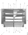
- the gas furnace system 20 includes a housing 22 having a plurality of exterior walls 24, 26, 28 and an interior dividing wall 30 that forms a heat exchange portion 32 and a blower portion 34.
- Heat exchange portion 32 includes a component support wall 36 which, as will be discussed more fully below, provides structure for mounting various components of the gas furnace system 20.
- Housing 22 is also shown to include an access panel 38 that provides access to the blower portion 34 and another access panel (not shown) that provides access to heat exchange portion 32.
- the gas furnace system 20 additionally includes a burner assembly 40 mounted to component support wall 36.
- Burner assembly 40 includes a burner box 42 and a gas valve 44.
- Burner assembly 40 combusts a fuel, in the form of gas, to generate heat used to condition a comfort zone such as living spaces, work spaces and the like.
- a comfort zone such as living spaces, work spaces and the like.
- products of combustion or exhaust gases generated by the burning of the fuel are expelled to ambient.
- burner assembly 40 is operatively connected to a primary heat exchanger 46 arranged within heat exchange portion 32.
- Primary heat exchanger 46 is operatively coupled to a condensing heat exchanger 48.
- Condensing heat exchanger 48 includes a plurality of heat exchange members 50.
- a blower assembly 52 arranged within the blower portion 34 draws in air from a space to be heated.
- the air is guided over primary heat exchanger 46 and heat exchange members 50 of condensing heat exchanger 48 such that the air is heated before being re-introduced into the space.
- Gas furnace system 20 further includes an inducer fan assembly 58 mounted to condensate collector box 54.
- Inducer fan assembly 58 creates an air flow that establishes a draft which draws the products of combustion from burner box 42 through primary heat exchanger 46 and heat exchange members 50 of the condensing heat exchanger 48. More specifically, inducer fan assembly 58 produces a pressure rise and flow rate to achieve a desired combustion performance while overcoming flow losses within gas furnace system 20. The products of combustion are then exhausted through a flue vent 60.
- the blower assembly 52 is illustrated in more detail. Although the blower assembly 52 is illustrated and described herein with reference to a furnace, it should be understood that the blower assembly 52 may be used in other suitable applications, such as in an air handling unit of an HVAC and/or refrigeration system for example.
- the blower assembly 52 includes a fan wheel 62 positioned within a blower housing 64.
- the blower housing 64 has an outer wall 66 having a scroll-shaped length that extends from a first end edge 68 to an opposite second end edge 70.
- the first end edge 68 and the second end edge 70 define opposite sides of an outlet opening 72 of the blower housing 64.
- the blower housing 64 additionally includes a first sidewall 74 and a second sidewall 76. As seen in the FIG., portions of the peripheries of the first sidewall 74 and the second sidewall 76 are connected to opposite sides of the outer wall 66.
- the first sidewall 74 has a first straight edge portion 78 extending between the outer wall first end edge 68 and the outer wall second end edge 70 and the second sidewall 76 similarly has a second straight edge portion 80 extending between the outer wall first end edge 68 and the outer wall second end edge 70.
- the first sidewall 74 includes a first aperture 82 and the second sidewall includes a second aperture (not shown).
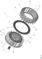
- the fan wheel 62 is illustrated in more detail.
- the fan wheel 62 is typically formed as an assembly of three primary components: a first wheel portion 100, a second wheel portion 102, and a support ring 104 located centrally between the first wheel portion 100 and the second wheel portion 102.
- a blower assembly 52 of a furnace system such as system 20 of FIG. 1
- both the first wheel portion 100 and the second wheel portion 102 are configured to provide air to an adjacent component and are associated with a single plenum.
- the first wheel portion 100 includes a shroud 106 and a first plurality of impeller blades 108 spaced about a periphery of the shroud 106 and connected thereto at a first end 110.
- the second wheel portion 102 similarly includes a shroud 112 and a second plurality of impeller blades 114 arranged about a periphery of the shroud 112 and connected thereto at a first end 116.
- one or both of the first plurality and the second plurality of impeller blades 108, 114 are configured as backward curved impeller blades.
- embodiments where one or both of the first plurality and second plurality of impeller blades 108, 114 have a forward curved configuration, or another configuration are also contemplated herein.
- the first wheel portion 100 is dissimilar from the second wheel portion 102 such that the fan wheel 62 has an asymmetrical configuration about a plane oriented parallel to an intersecting the support ring 104.
- Examples of a fan blower 62 having an asymmetrical configuration are disclosed in WO 2018/075635 .
- embodiments where the first wheel portion 100 and the second wheel portion 102 have a symmetric configuration are also considered within the scope of the disclosure.
- the support ring 104 is configured to connect to the second end 118, 120 of both the first plurality of impeller blades 108 and the second plurality of impeller blades 114, respectively. Accordingly, the support ring 104 forms a barrier separating the blades 108, 114 of the first wheel portion 100 and a second wheel portion 102. As a result, the first plurality of impeller blades 108 is axially spaced from the second plurality of impeller blades 114.
- the support ring 104 has a generally planar configuration.
- the support ring 104 has a central opening 122 and an inner diameter of the central opening 122 is slightly greater than or equal to the inner diameter defined by an inner edge 124, 126 of at least one of the first plurality and the second plurality of impeller blades 108, 114, respectively.
- an outer diameter of the support ring 104 is generally equal to the outer diameter of the fan wheel 62 which may be defined by an outer edge 128, 129 of at least one of the first plurality and the second plurality of impeller blades 108, 114.
- a circular connector 130, 132 couples the inner edge 124, 126 of the second end 118, 120 of each the first plurality of impeller blades 108 and the second plurality of impeller blades 114, respectively.
- a central hub 134 for mounting the fan wheel 62 to a drive shaft 136 for rotation about an axis X is coupled to the connector 130 of the first wheel portion 100.
- the central hub 134 and the connector 130 may be integrally formed, or alternatively, may be connected, such as via fasteners or another suitable connection mechanism.
- a diameter of the central hub 134 is generally complementary to or receivable within the hollow interior of the support ring.
- first wheel portion 100 is illustrated as incorporating the central hub 134, embodiments where the second wheel portion 102 alternatively includes the hub 134 are also within the scope of the disclosure.
- first wheel portion 100, second wheel portion 102, and support ring 104 is formed from a polymer or plastic material having a suitable fire rating.
- suitable materials include, but are not limited to a glass fiber reinforced, flame retardant, Polyamide 6, such as Schulamid ® 6 GBF 3015 FR 4 for example, Polyamide 66, such as Ultramid ® 66 H2 G/35-V0KB1 BK3324 for example, and a Nylon 6/6, such as RTP 299 X 141130 B for example.
- the material selected for at least one of the first wheel portion 100, second wheel portion 102, and support ring 104 will satisfy the testing standards of the UL certification LTL94 V-0, 5VA.
- first wheel portion 100, second wheel portion 102, and support ring 104 may be the same, or alternatively, may be different. Further, in an embodiment, the support ring 104 may be formed from a material having a reduced amount of glass fiber compared to at least one of the first wheel portion 100 second wheel portion 102.
- the support ring 104 includes a plurality of blade receiving areas spaced about the periphery thereof. As shown, a first plurality of blade receiving areas 140 formed in a first surface 142 of the support ring are adapted to receive the second ends 118 of the first plurality of impeller blades 108, respectively. Similarly, a second plurality of blade receiving areas 144 formed in a second, opposite surface 146 of the support ring 104 are adapted to receive the second ends 120 of the second plurality of impeller blades 114, respectively. As shown, the first plurality of blade receiving areas 140 is substantially aligned with the second plurality of blade receiving areas 144 (see FIGS. 8 and 10 ). However, embodiments, where the first plurality of blade receiving areas 140 are offset from the second plurality of blade receiving areas 144, as shown in FIG. 11 , are also contemplated herein.
- each of the blade receiving areas 140, 144 includes a land 150 defined by a first groove 152 located adjacent a first side of the land 150, and a second groove 154 positioned adjacent a second side of the land.
- a second end 118, 120 of a corresponding impeller blade 108, 114 is positioned in direct contact with the surface of the land 150.
- the second end 118, 120 of the corresponding impeller blade 108, 114 and the land 150 are attached, such as via a welding operation for example, to integrally form the end 118, 120 of the impeller blade 108, 114 with the support ring 104.
- the land 150 and/or the blades 108, 114 are heated, a force is applied to the blade 108, 114 such that the end 118, 120 of the blade 108, 114 displaces all or a portion of the material of the land 150.
- one or both of the first and second grooves 152, 154 positioned adjacent each land 150 may fill at least partially with overflow material generated by affixing the blade end 118, 120 to the land 150 of the support ring 104.
- a nesting fixture 160 is received within the hollow interior of the first wheel portion 100 and/or the second wheel portion 102.
- One or more grooves 162 may be formed in the outer periphery 164 of the nesting fixture 160.
- the grooves 162 are sized to receive the inner end 124, 126 of the plurality of impeller blades 108, 114 of a corresponding wheel portion 100, 102.
- the nesting fixture 160 maintains an orientation of the blades 108, 114 as heat is applied thereto and the blades 108, 114 are forced into contact with blade receiving areas 140, 144 of the support ring 104.
- the nesting fixture 160 includes one or more indexing features 166 that align with a corresponding notch or cavity formed in the support ring 104. Inclusion of these indexing features 166 ensures that the nesting fixture 160 is always arranged in the same orientation relative to the support ring 104 during a welding operation.
- the blade receiving areas 140, 144 include pockets 170 formed in the first and/or second surface 142, 146 of the support ring 104.
- the pockets 170 may be formed by one or more sidewalls 172 that extend from a surface 142, 146 of the support ring 104 and that define an opening 174 there between.
- the opening 174 is generally complementary, i.e. has a similar size and shape to the second end 118, 120 of the impeller blade 108, 114 being received therein.
- the blades 108, 114 are coupled to the support ring 104 mechanically, and no further attachment process, such as a welding operation for example, is required to couple the wheel portions 100, 102 to the support ring 104.
- the circular connectors 130, 132 of both the first and second wheel portions 100, 102 are positioned directly proximate one another, as best shown in FIG. 9 .
- the circular connectors 130, 132 may similarly be coupled to one another.
- a welding operation is used to attach the circular connectors 130, 132.
- Heat may be applied at the interface between the circular connectors 130, 132, each of which similarly includes a raised surface 180 and a first and second groove 182, 184 disposed on opposing sides of the raised surface 180.
- the raised surfaces 180 in melt together to integrally form the circular connectors 130, 132.
- the melted material may additionally flow from the raised surfaces 180 into one or both of the first and second grooves 182, 184.
- a welding operation such as the application of heat for example, may be used to couple the circular connectors 130, 132, regardless of whether the wheel portions 100, 102 are welded, mechanically connected using fasteners or molded in snap features, or over-molded to the support ring 104.
- the fan wheel 62 as illustrated and described herein has an improved efficiency compared to conventional fan wheels 62.
- a motor having a decreased horsepower can be used to satisfy regulatory furnace efficiency requirements.
- the use of plastic molding and the manufacturing processes associated therewith result in reduced clearances and refined blade aerodynamic profiles which may increase the aerodynamic performance of the fan wheel.
- blower assembly 52 illustrated and described herein has an improved efficiency compared to conventional blower assemblies.
- the blower assembly 52 may be adapted for use in the blower portion 34 of existing furnaces 20 without requiring modification of the cabinet or housing.
- Embodiment 1 A method of assembling a fan wheel comprising: forming a first wheel portion including a first plurality of impeller blades and a first connector; forming a second wheel portion including a second plurality of impeller blades and a second connector; affixing an end of each of the first plurality of impeller blades to a first surface of a support ring such that the first connector is affixed to the second connector; and affixing an end of each of the second plurality of impeller blades to a second surface of a support ring.
- Embodiment 2 The method of embodiment 1, wherein the first wheel portion is formed separately from the second wheel portion.
- Embodiment 3 The method of embodiment 1, wherein affixing the end of the first plurality of impeller blades to the first surface of a support ring includes positioning the ends of the first plurality of impeller blades at a plurality of blade receiving areas of the first surface of the support ring.
- Embodiment 4 The method of embodiment 3, wherein positioning the ends of the first plurality of impeller blades at a plurality of blade receiving areas of the first surface includes positioning the ends of the first plurality of impeller blades within a plurality of pockets formed in the first surface of the support ring.
- Embodiment 5 The method of embodiment 4, wherein each of the pockets further comprises a first sidewall, a second sidewall, and an opening defined between the first sidewall and the second sidewall, and positioning the ends of the first plurality of impeller blades within the plurality of pockets further comprises installing the ends of the first plurality of impeller blades within the openings of the plurality of pockets.
- Embodiment 6 The method of embodiment 3, wherein each of the plurality of blade receiving areas includes a land and at least one groove adjacent the land, and positioning the ends of the first plurality of impeller blades at a plurality of blade receiving areas of the first surface includes further comprises positioning the ends of the first plurality of impeller blades in direct contact with the plurality of lands.
- Embodiment 7 The method of embodiment 6, wherein affixing an end of each of the first plurality of impeller blades to a first surface of a support ring further comprises welding the ends to the plurality of blade receiving areas of the first surface of the support ring.
- Embodiment 8 The method of embodiment 7, wherein welding the ends to the plurality of blade receiving areas of the first surface of the support ring further comprises welding the ends of the first plurality of impeller blades to the plurality of lands.
- Embodiment 9 The method of embodiment 8, wherein welding the ends of the first plurality of impeller blades to the plurality of lands displaces a portion of material of the lands into the at least one groove.
- Embodiment 10 The method of embodiment 1, wherein coupling the first connector and the second connector includes welding the first connector to the second connector.
- Embodiment 11 The method of embodiment 1, wherein at least one of the first wheel portion and the second wheel portion is formed via a plastic molding process.
- Embodiment 12 A fan wheel for use in a blower assembly, comprising: a first wheel portion including a first plurality of impeller blades; a second wheel portion including a second plurality of impeller blades; a support disk positioned near a center of the fan wheel, between the first wheel portion and the second wheel portion, wherein the support disk couples the first wheel portion to the second wheel portion and at least one of the first wheel portion, the second wheel portion, and the support disk is formed from a plastic material.
- Embodiment 13 The fan wheel of embodiment 12, wherein the first wheel portion, the second wheel portion, and the support ring are formed separately.
- Embodiment 14 The fan wheel of embodiment 12, wherein the fan wheel includes a first plurality of blade receiving areas formed in a first surface and the fan wheel includes a second plurality of blade receiving areas formed in a second, opposite surface.
- Embodiment 15 The fan wheel of embodiment 14, wherein the first plurality of impeller blades are welded to the first plurality of blade receiving areas.
- Embodiment 16 The fan wheel of embodiment 14, wherein the first plurality of impeller blades are mechanically coupled to the first plurality of blade receiving areas.
- Embodiment 17 The fan wheel of embodiment 16, wherein the first plurality of blade receiving areas include a plurality of pockets including openings complementary to the first plurality of impeller blades.
- Embodiment 18 The fan wheel of embodiment 14, wherein the first wheel portion further comprises a first connector and the second wheel portion further comprises a second connector and the first connector is coupled to the second connector.
- Embodiment 19 The fan wheel of embodiment 14, wherein the first connector is welded to the second connector.
Applications Claiming Priority (2)
| Application Number | Priority Date | Filing Date | Title |
|---|---|---|---|
| US201862623900P | 2018-01-30 | 2018-01-30 | |
| EP19154328.9A EP3517784B1 (fr) | 2018-01-30 | 2019-01-29 | Rouet de ventilateur constitué de deux parties aubagées connectées axialement l'une à l'autre |
Related Parent Applications (1)
| Application Number | Title | Priority Date | Filing Date |
|---|---|---|---|
| EP19154328.9A Division EP3517784B1 (fr) | 2018-01-30 | 2019-01-29 | Rouet de ventilateur constitué de deux parties aubagées connectées axialement l'une à l'autre |
Publications (2)
| Publication Number | Publication Date |
|---|---|
| EP4290083A2 true EP4290083A2 (fr) | 2023-12-13 |
| EP4290083A3 EP4290083A3 (fr) | 2024-03-13 |
Family
ID=65243452
Family Applications (2)
| Application Number | Title | Priority Date | Filing Date |
|---|---|---|---|
| EP23198649.8A Pending EP4290083A3 (fr) | 2018-01-30 | 2019-01-29 | Rouet de ventilateur constitué de deux parties aubagées connectées axialement l'une à l'autre |
| EP19154328.9A Active EP3517784B1 (fr) | 2018-01-30 | 2019-01-29 | Rouet de ventilateur constitué de deux parties aubagées connectées axialement l'une à l'autre |
Family Applications After (1)
| Application Number | Title | Priority Date | Filing Date |
|---|---|---|---|
| EP19154328.9A Active EP3517784B1 (fr) | 2018-01-30 | 2019-01-29 | Rouet de ventilateur constitué de deux parties aubagées connectées axialement l'une à l'autre |
Country Status (3)
| Country | Link |
|---|---|
| US (2) | US11041502B2 (fr) |
| EP (2) | EP4290083A3 (fr) |
| BR (1) | BR102019001686A2 (fr) |
Families Citing this family (3)
| Publication number | Priority date | Publication date | Assignee | Title |
|---|---|---|---|---|
| EP3529496A1 (fr) | 2016-10-18 | 2019-08-28 | Carrier Corporation | Souffleur courbé vers l'arrière à double entrée asymétrique |
| US11041502B2 (en) | 2018-01-30 | 2021-06-22 | Carrier Corporation | Double inlet backward curved blower |
| WO2024064414A1 (fr) * | 2022-09-23 | 2024-03-28 | Cleva Technologies, Llc | Ensemble de pales de ventilateur à turbine mobile |
Citations (1)
| Publication number | Priority date | Publication date | Assignee | Title |
|---|---|---|---|---|
| WO2018075635A1 (fr) | 2016-10-18 | 2018-04-26 | Carrier Corporation | Souffleur courbé vers l'arrière à double entrée asymétrique |
Family Cites Families (49)
| Publication number | Priority date | Publication date | Assignee | Title |
|---|---|---|---|---|
| JPS5117005A (ja) | 1974-08-02 | 1976-02-10 | Matsushita Electric Ind Co Ltd | Ryutaikikaiyoentogatahaneguruma |
| JPS55114897A (en) * | 1979-02-27 | 1980-09-04 | Mikuni Plast Kk | Cross flow impeller |
| DE3247453C1 (de) | 1982-12-22 | 1983-12-15 | Funken & Co GmbH, 5200 Siegburg | Ventilatorlaufrad und Verfahren zu seiner Herstellung |
| DE58901573D1 (de) | 1988-06-30 | 1992-07-09 | Siemens Ag | Ausgewuchtetes luefterrad sowie verfahren und vorrichtung zur herbeifuehrung des unwuchtausgleiches. |
| JPH07103190A (ja) | 1993-10-06 | 1995-04-18 | Takao Kobayashi | 軽量・低騒音型のターボファン用羽根車の構造。 |
| US6508627B2 (en) | 2001-05-30 | 2003-01-21 | Lau Industries, Inc. | Airfoil blade and method for its manufacture |
| JP4507553B2 (ja) * | 2003-10-23 | 2010-07-21 | パナソニック株式会社 | クロスフローファン及びクロスフローファンの製造方法 |
| US7108482B2 (en) | 2004-01-23 | 2006-09-19 | Robert Bosch Gmbh | Centrifugal blower |
| JP5240926B2 (ja) | 2005-07-04 | 2013-07-17 | ベール ゲーエムベーハー ウント コー カーゲー | 羽根車 |
| JP3901200B2 (ja) | 2005-08-05 | 2007-04-04 | ダイキン工業株式会社 | 樹脂製クロスフローファン及びその製造方法 |
| CN1862029B (zh) | 2005-08-29 | 2010-06-30 | 刘希文 | 涡扇戽斗螺旋离心叶轮及该叶轮在流体输送中的应用方法 |
| WO2007033274A2 (fr) | 2005-09-13 | 2007-03-22 | Ingersoll-Rand Company | Impulseur pour compresseur centrifuge |
| WO2007037699A1 (fr) * | 2005-09-27 | 2007-04-05 | Umoe Mandal As | Ventilateur centrifuge |
| JP3995010B2 (ja) | 2005-09-28 | 2007-10-24 | ダイキン工業株式会社 | 多翼送風機の羽根車及びその製造方法 |
| CN100559031C (zh) | 2005-10-06 | 2009-11-11 | 三菱电机株式会社 | 涡轮风扇和空调机 |
| JP4876784B2 (ja) | 2006-08-24 | 2012-02-15 | パナソニック株式会社 | 両吸込型遠心送風機 |
| US20080279682A1 (en) * | 2007-03-06 | 2008-11-13 | Larry David Wydra | Impeller Assembly and Method of Using Same |
| US7762778B2 (en) | 2007-05-17 | 2010-07-27 | Kurz-Kasch, Inc. | Fan impeller |
| ES2607841T3 (es) | 2009-03-25 | 2017-04-04 | Ebm-Papst Mulfingen Gmbh & Co. Kg | Ventilador radial |
| DE102009002418A1 (de) | 2009-04-16 | 2010-10-21 | Robert Bosch Gmbh | Lüfterrad für ein Gebläsemodul |
| CN101846087B (zh) | 2010-05-11 | 2011-09-14 | 东元总合科技(杭州)有限公司 | 离心风扇及设有该离心风扇的密闭式电机 |
| US11136992B2 (en) | 2010-08-05 | 2021-10-05 | Regal Beloit America, Inc. | High efficiency blower housing with unequal size inlet openings |
| TWI465184B (zh) | 2010-12-20 | 2014-12-11 | Sunonwealth Electr Mach Ind Co | 風扇模組 |
| US9140270B2 (en) | 2011-09-14 | 2015-09-22 | Brose Fahrzeugteile GmbH & Co. Kommanditgesellschaft, Würzburg | Centrifugal fan assembly |
| US9267507B2 (en) | 2011-10-05 | 2016-02-23 | Asia Vital Components Co., Ltd. | Blade structure for centrifugal fan |
| DE202011052411U1 (de) | 2011-12-21 | 2013-03-22 | Ebm-Papst Mulfingen Gmbh & Co. Kg | Schaufelrad für Axialventilatoren oder Radial- und Diagonallüfter |
| US9017011B2 (en) | 2011-12-29 | 2015-04-28 | Regal Beloit America, Inc. | Furnace air handler blower with enlarged backward curved impeller and associated method of use |
| US9109605B2 (en) * | 2012-04-24 | 2015-08-18 | Asia Vital Components Co., Ltd. | Fan impeller structure and manufacturing method thereof |
| JP5590081B2 (ja) | 2012-09-04 | 2014-09-17 | ダイキン工業株式会社 | クロスフローファン |
| CN202851448U (zh) | 2012-09-06 | 2013-04-03 | 江苏友奥电器有限公司 | 一种后向离心风叶 |
| JP2014134163A (ja) | 2013-01-11 | 2014-07-24 | Nisshinbo Mechatronics Inc | 送風機用羽根車 |
| US9689264B2 (en) | 2013-03-15 | 2017-06-27 | Regal Beloit America, Inc. | Centrifugal fan impeller with variable shape fan blades and method of assembly |
| JP6341637B2 (ja) | 2013-06-14 | 2018-06-13 | 三菱電機株式会社 | 遠心送風機の製造方法 |
| US20150071800A1 (en) | 2013-09-10 | 2015-03-12 | Samsung Electro-Mechanics Co., Ltd. | Impeller for electric blower and electric blower having the same |
| JP6001520B2 (ja) | 2013-11-01 | 2016-10-05 | 日清紡メカトロニクス株式会社 | ターボファンの製造方法 |
| CN103696985A (zh) | 2013-11-30 | 2014-04-02 | 宁波方太厨具有限公司 | 一种离心风机的叶轮 |
| CN104747495A (zh) | 2013-12-26 | 2015-07-01 | 珠海格力电器股份有限公司 | 前向式离心风叶、离心风机及其空调器 |
| CN203685679U (zh) | 2014-01-23 | 2014-07-02 | 珠海格力电器股份有限公司 | 离心风叶、离心风机和空调器 |
| CN104806567A (zh) | 2014-01-23 | 2015-07-29 | 珠海格力电器股份有限公司 | 离心风叶、离心风机和空调器 |
| CN103807209A (zh) | 2014-02-13 | 2014-05-21 | 沈阳斯特机械制造有限公司 | 一种离心压缩机的闭式叶轮 |
| US9933185B2 (en) * | 2014-02-24 | 2018-04-03 | Noritz Corporation | Fan and water heater provided with the same, and impeller and water heater provided with the same |
| CN203879799U (zh) | 2014-05-30 | 2014-10-15 | 江苏友奥电器有限公司 | 一种双吸离心风叶 |
| CN203879801U (zh) | 2014-06-04 | 2014-10-15 | 江苏友奥电器有限公司 | 一种双吸式离心风叶 |
| JP6366389B2 (ja) | 2014-07-03 | 2018-08-01 | 株式会社日本クライメイトシステムズ | ファンの取付構造 |
| CN105090107A (zh) | 2015-07-21 | 2015-11-25 | 依必安派特风机(上海)有限公司 | 后向离心风机叶轮以及离心风机 |
| CN204961385U (zh) | 2015-07-21 | 2016-01-13 | 依必安派特风机(上海)有限公司 | 后向离心风机叶轮以及离心风机 |
| CN105179281A (zh) | 2015-10-12 | 2015-12-23 | 珠海格力电器股份有限公司 | 风机及具有其的空调系统 |
| JP6210104B2 (ja) | 2015-10-30 | 2017-10-11 | ダイキン工業株式会社 | クロスフローファン |
| US11041502B2 (en) | 2018-01-30 | 2021-06-22 | Carrier Corporation | Double inlet backward curved blower |
-
2019
- 2019-01-14 US US16/246,939 patent/US11041502B2/en active Active
- 2019-01-28 BR BR102019001686-8A patent/BR102019001686A2/pt not_active Application Discontinuation
- 2019-01-29 EP EP23198649.8A patent/EP4290083A3/fr active Pending
- 2019-01-29 EP EP19154328.9A patent/EP3517784B1/fr active Active
-
2021
- 2021-06-21 US US17/353,389 patent/US11873831B2/en active Active
Patent Citations (1)
| Publication number | Priority date | Publication date | Assignee | Title |
|---|---|---|---|---|
| WO2018075635A1 (fr) | 2016-10-18 | 2018-04-26 | Carrier Corporation | Souffleur courbé vers l'arrière à double entrée asymétrique |
Also Published As
| Publication number | Publication date |
|---|---|
| BR102019001686A2 (pt) | 2019-09-17 |
| EP3517784B1 (fr) | 2023-10-18 |
| EP3517784A1 (fr) | 2019-07-31 |
| EP4290083A3 (fr) | 2024-03-13 |
| US11041502B2 (en) | 2021-06-22 |
| US11873831B2 (en) | 2024-01-16 |
| US20210310497A1 (en) | 2021-10-07 |
| US20190234418A1 (en) | 2019-08-01 |
Similar Documents
| Publication | Publication Date | Title |
|---|---|---|
| US11873831B2 (en) | Double inlet backward curved blower | |
| US11242864B2 (en) | Asymmetric double inlet backward curved blower | |
| KR101727901B1 (ko) | 원심팬 및 원심팬의 제조방법 | |
| EP1878923B1 (fr) | Turbine de ventilateur centrifuge et ventilateur centrifuge disposé avec la turbine | |
| US8732948B2 (en) | Method of manufacturing impeller for centrifugal blower | |
| US8573343B2 (en) | Vehicle heat-exchange module and vehicle having the same | |
| US9920768B2 (en) | Centrifugal fan assembly | |
| US10844770B2 (en) | Cooling fan module | |
| US8584664B2 (en) | Inducer fan assembly for a furnace | |
| AU2017427465B2 (en) | Propeller fan, air-sending device, and refrigeration cycle apparatus | |
| US6881035B1 (en) | Draft inducer having single piece metal impeller and improved housing | |
| KR200436612Y1 (ko) | 공기조화기용 양흡입 블로아 | |
| US6908281B2 (en) | Blower housing for furnace blower assembly | |
| EP2594847B1 (fr) | Système motorisé de tirage de cheminée et turbine pour une utilisation dans le système | |
| CN212130840U (zh) | 离心式风扇叶片组件 | |
| US11499716B2 (en) | Furnace subassembly, furnace blower and associated method | |
| KR102560344B1 (ko) | 균일풍량생성형 송풍기 | |
| CN219177828U (zh) | 空调器 | |
| CN209857191U (zh) | 风道组件、风道部件和空调器 | |
| TWI388731B (zh) | 軸流式風扇及其扇輪 | |
| KR101897240B1 (ko) | 차량 냉각팬용 쉬라우드 조립체 | |
| KR20020009660A (ko) | 일체형 공기조화기의 오리피스 설치구조 |
Legal Events
| Date | Code | Title | Description |
|---|---|---|---|
| PUAI | Public reference made under article 153(3) epc to a published international application that has entered the european phase |
Free format text: ORIGINAL CODE: 0009012 |
|
| STAA | Information on the status of an ep patent application or granted ep patent |
Free format text: STATUS: THE APPLICATION HAS BEEN PUBLISHED |
|
| AC | Divisional application: reference to earlier application |
Ref document number: 3517784 Country of ref document: EP Kind code of ref document: P |
|
| AK | Designated contracting states |
Kind code of ref document: A2 Designated state(s): AL AT BE BG CH CY CZ DE DK EE ES FI FR GB GR HR HU IE IS IT LI LT LU LV MC MK MT NL NO PL PT RO RS SE SI SK SM TR |
|
| REG | Reference to a national code |
Ref country code: DE Ref legal event code: R079 Free format text: PREVIOUS MAIN CLASS: F04D0029620000 Ipc: F04D0017160000 |
|
| PUAL | Search report despatched |
Free format text: ORIGINAL CODE: 0009013 |
|
| AK | Designated contracting states |
Kind code of ref document: A3 Designated state(s): AL AT BE BG CH CY CZ DE DK EE ES FI FR GB GR HR HU IE IS IT LI LT LU LV MC MK MT NL NO PL PT RO RS SE SI SK SM TR |
|
| RIC1 | Information provided on ipc code assigned before grant |
Ipc: F04D 29/62 20060101ALI20240202BHEP Ipc: F04D 29/28 20060101ALI20240202BHEP Ipc: F04D 29/02 20060101ALI20240202BHEP Ipc: F04D 17/16 20060101AFI20240202BHEP |