EP4290001B1 - Métier à tricoter chaîne - Google Patents
Métier à tricoter chaîne Download PDFInfo
- Publication number
- EP4290001B1 EP4290001B1 EP22178316.0A EP22178316A EP4290001B1 EP 4290001 B1 EP4290001 B1 EP 4290001B1 EP 22178316 A EP22178316 A EP 22178316A EP 4290001 B1 EP4290001 B1 EP 4290001B1
- Authority
- EP
- European Patent Office
- Prior art keywords
- pivot axis
- warp knitting
- linear guide
- lever
- knitting loom
- Prior art date
- Legal status (The legal status is an assumption and is not a legal conclusion. Google has not performed a legal analysis and makes no representation as to the accuracy of the status listed.)
- Active
Links
Images


Classifications
-
- D—TEXTILES; PAPER
- D04—BRAIDING; LACE-MAKING; KNITTING; TRIMMINGS; NON-WOVEN FABRICS
- D04B—KNITTING
- D04B27/00—Details of, or auxiliary devices incorporated in, warp knitting machines, restricted to machines of this kind
- D04B27/06—Needle bars; Sinker bars
- D04B27/08—Driving devices therefor
Definitions
- the present invention relates to a warp knitting machine with a slider needle bar having a plurality of slider needles and a drive acting on the slider needle bar, which drive has a linear guide with a first part and a second part movable relative to the first part, wherein the first part can be pivoted with a pivoting movement about a pivot axis and the second part is connected to the slider needle bar.
- knitting or working needles which in this case are designed as slider needles, must be moved relative to the guide needles in such a way that the knitting needles are moved through the channels between the guide needles.
- This movement can be achieved by pivoting the guide needles, which are attached to a guide needle bar, or by pivoting the slider needles with the slider needle bar relative to the guide needle bar. The latter movement is particularly found in Raschel machines.
- the EP 3 216 903 B1 discloses a warp knitting machine, wherein the linear movement of the slide bar carrier is effected by a direct drive having a slide bar tappet.
- the slide bar tappet has a base point provided with a roller that rests against the main shaft.
- the slide bar tappet is moved in a direction parallel to a longitudinal axis and is connected to the slide bar carrier at the end facing away from the base point via a joint.
- the invention is based on the object of generating the movement of a slider needle bar in a Raschel machine in a simple manner.
- pivot axis is a first pivot axis and the second part is articulated to a rod which can be pivoted about a second pivot axis which is separate from the first pivot axis.
- the first pivot axis, the second pivot axis, and the articulation point at which the rod is connected to the second part form a triangle.
- the angles of this triangle change. This change in angle then leads to a change in the side of the triangle on which the linear guide is arranged.
- the change in the length of this side of the triangle is possible because the second part is movable relative to the first part of the linear guide.
- the linear movement of the second part can therefore be generated easily, without having to use a cam disk.
- the linear movement of the second part of the linear guide relative to the first part is generated exclusively via the rod.
- crank mechanism is connected to the first part via a lever. This allows a certain gear ratio to be achieved so that the swivel angle can be adjusted relatively precisely.
- the second pivot axis can be moved in synchronism with the pivoting movement of the linear guide. If the second pivot axis is moved in synchronism with the pivoting movement of the linear guide, then the second pivot axis still forms a corner point of the triangle mentioned above. However, by moving the second pivot axis, you can ensure that the slider needle bar moves on a different curved path when it pivots in one direction than when it pivots in the opposite direction. In simple terms, the curved path made up of two sections then describes a "droplet shape". In this way, you can ensure that the slider needles can each grab a thread when the linear guide pivots in one direction, and that the slider needles do not come into conflict with threads when they move in the other direction, but are guided past them at a certain distance.
- the crank drive is a first crank drive and the lever is a first lever and the second pivot axis is arranged on a second lever which can be pivoted about a third pivot axis, wherein the second lever can be pivoted with the aid of a second crank drive which operates with a phase shift to the first crank drive.
- the two crank drives operate synchronously, but with a certain phase shift. With this phase shift, the course of the trajectory of the slide needle bar is relatively preset to the path of a slide bar, whereby the movement of the slide needle bar in one pivoting direction occurs but on a different path than the movement in the opposite direction.
- the linear guide is a first linear guide and the warp knitting machine has a slide bar with sliders, the slide bar being connected to a second element of a second linear guide which is displaceable relative to a first element of the second linear guide, the first element of the second linear guide being pivotable about the first pivot axis and the second element being articulated to a second rod which is displaceable about a fourth pivot axis which is separate from the first pivot axis and the second pivot axis.
- the movement of the slide bar can then be controlled in a similar way to the movement of the slide needle bar.
- the sliders and the slide needles can then be moved in a similar way in a simple manner with the only difference being that the sliders are moved linearly relative to the slide needles in order to close or open a catch space of the slide needles.
- the fourth pivot axis is displaceable. By displacing the fourth pivot axis, it is possible to ensure that the slide bar follows a different path of motion when pivoting in one direction than when moving in the opposite direction. The slides can then follow the movement of the slide needles with greater accuracy.
- the fourth pivot axis can be displaced on a circular arc around the third pivot axis.
- Such a displacement can be implemented relatively easily.
- the second pivot axis and the fourth pivot axis can be moved with the same phase position. This results in a synchronous movement of the sliding needle bar and the slide bar with the difference mentioned above that the slides can open or close the catch area of the sliding needles.
- the fourth pivot axis is arranged on a third lever that can pivot about the third pivot axis. This is a simple way of moving the fourth pivot axis on a circular arc.
- the second crank mechanism engages the third lever.
- the second crank mechanism then pivots the third lever about the third pivot axis and can thus shift the fourth pivot axis.
- the first linear guide and the second linear guide can be displaced together about the first pivot axis. This makes it possible to achieve the desired synchronous pivoting movement of the slide needle bar and slide bar.
- a knock-off element bar is arranged so that it can pivot about the first pivot axis.
- the knock-off element bar only needs to be pivoted. A superposition with a linear movement is not necessary here.
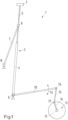
- Fig. 1 shows a highly schematic view of part of a warp knitting machine, namely a drive 1 of a slider needle bar 2.
- the slider needle bar 2 has a plurality of slider needles in a manner not shown in detail but known per se.
- the slider needle bar 2 is arranged on a linear guide 3 which has a first part 4 and a second part 5 which is movable relative to the first part 4 and to which the slider needle bar 2 is connected.
- the first part 4 can be pivoted about a pivot axis 6.
- the second part 5 is articulated to a rod 7 which can be pivoted about a second pivot axis 8.
- the second pivot axis 8 is separate from the first pivot axis 6.
- the rod 7 is connected to the second part 5 via a pivot point 9.
- the first part 4 is connected in a rotationally fixed manner to a first lever 10, which can be pivoted via a first crank drive 11.
- the first crank drive 11 is driven by a main shaft 12 of the warp knitting machine.
- the crank drive 11 has a crank 14, which is connected via an intermediate lever 15 to a pivot point 16 arranged on the first lever 10.
- the crank 14 is connected to the intermediate lever via a pivot point 17.
- the first part 4 of the linear guide 3 then moves with the same pivoting movement as the first lever 10.
- the first swivel axis 6, the second swivel axis 8 and the hinge point 9 form a triangle.
- the linear guide 3 is swiveled, the angles of the triangle. If the linear guide 3 is pivoted clockwise around the first pivot axis 6 (relative to the representation of the Fig. 1 ), then the side opposite the second pivot axis 8 shortens and the second part 5 of the linear guide 3 moves into the first part 4.
- the slide needle bar 2 is then not only pivoted clockwise, but also moves towards the first pivot axis 6.
- the movement path of the slide needle bar 2 thus deviates from a circular arc in the desired manner.
- the linear guide 3 pivots anti-clockwise, the second part 5 moves out of the first part 4 of the linear guide 3 again, thus moving away from the first pivot axis 6.
- a slider needle bar 2 In the warp knitting machine, however, not only a slider needle bar 2 must be moved, but also a slider bar and a knock-off element bar.
- the slider bar carries a slider for each slider needle, which opens or closes a catch area for the respective slider needle.
- the slider needle bar must therefore be controlled with a similar movement curve to the slider needle bar 2.
- a knock-off element bar For the knock-off element bar, however, a swivel movement is sufficient. An overlay by a linear movement is not necessary here.
- Fig. 2 shows schematically the drive 1, which in connection with Fig. 1 described, and additionally a drive for a slide bar and for a knock-off element bar.
- the slide bar and the knock-off element bar, as well as the slide needle bar, are not shown. Only a movement curve 18 for the slide needle bar, a movement curve 19 for the slide bar and a movement curve 20 for the knock-off element bar are shown.
- a second linear guide is provided, which is Fig. 2 is not visible.
- the second linear guide is located perpendicular to the drawing plane behind the linear guide 3, which is referred to below as the "first linear guide”.
- the second linear guide has a first element that can be pivoted about the first pivot axis 6 and a second element that can be moved linearly relative to the first element of the second linear guide.
- the second element is connected in an articulated manner to a second rod 21 that can be pivoted about a fourth pivot axis 22 that is separate from the first pivot axis 6 and the second pivot axis 8.
- the connection between the second rod 21 and the second element is made via a hinge point 23.
- first pivot axis 6, the fourth pivot axis 22 and the articulation point 23 form a triangle whose angle changes when the second linear guide is pivoted about the first pivot axis 6.
- the fourth pivot axis 22 is shown here on the other side of the first linear guide 3 than the second pivot axis 8.
- the fourth pivot axis 22 can also be arranged on the same side as the second pivot axis 8. If the pivot axes 8, 22 are arranged on different sides of the first linear guide 3, opposite linear movement components occur. If they are arranged on the same side of the first linear guide 3, the linear movement components are in the same direction.
- the slide bar also results in a movement curve 19 that deviates from a circular shape.
- the movement curve 19 consists of two parts namely a pivoting movement corresponding to a circular arc and a superimposed linear movement generated via the second linkage 21.
- the knock-off element bar which is also not shown in detail, moves along the movement curve 20.
- the movement curve 20 corresponds to part of a circular arc. It is generated by the knock-off element bar being arranged on a lever (not shown in detail), which is also pivoted about the first pivot axis 6.
- Fig. 3 shows a design in which different movement paths can be achieved for the "forward movement” and for the “backward movement” of the slider needle bar 2.
- the same elements as in the Fig. 1 and 2 are provided with the same reference symbols.
- the second pivot axis 8 is no longer stationary, but can be moved on a circular arc.
- the second pivot axis 8 is arranged on a second lever 24, which can be pivoted about a third pivot axis 25.
- the second lever 24 is pivoted via a second crank drive 26, which works with a phase shift to the first crank drive 11.
- the phase shift can be small.
- the second crank drive 26 is also driven by the main shaft 12.
- the second crank drive 26 drives a third lever 28 with a pivoting movement via an intermediate rod 27.
- the third lever 28 is connected to the second lever 24 in a rotationally fixed manner.
- the second lever 24 and the third lever 28 are jointly pivotable about the third pivot axis 25.
- the intermediate rod 27 is connected to the third lever 28 via a hinge point 29.
- the fourth pivot axis 22 can also be moved during operation of the warp knitting machine.
- the fourth pivot axis 22 is arranged on the third lever 28.
- the second pivot axis 8 and the fourth pivot axis 22 are arranged on different sides of the linear guide 3. This representation has been chosen for reasons of clarity. It is also possible to arrange the two pivot axes 8, 22 on the same side of the linear guide 3.
- the position of the second pivot axis 8 and the fourth pivot axis 22 as well as the position of the third pivot axis 25 and the articulation point 29 in relation to the position of the linear guide 3 can in principle be freely selected. Depending on the selected positions, opposing linear movement components or linear movement components in the same direction then result. It therefore depends on the desired trajectory of the individual bars how the individual linear movement components are to be superimposed.
- the movement curves for the slide needle bar 2 and for the slide bar i.e. the curves 18, 19, look different when the respective linear guides are pivoted in one direction than the movement when the linear guides are pivoted in the opposite direction.
- This is shown schematically in Fig. 3 where the movement curve 18 has a first branch 18a and a second branch 18b.
- the movement curve 19 is also formed with two different branches, which are however so close to each other that they are in the Fig. 3 cannot be recognized.
Landscapes
- Engineering & Computer Science (AREA)
- Textile Engineering (AREA)
- Knitting Machines (AREA)
Claims (14)
- Métier à tricoter chaîne avec une barre d'aiguilles à coulisse (2), qui comporte une pluralité d'aiguilles à coulisse et un entraînement (1) agissant sur la barre d'aiguilles à coulisse (2) , qui comporte un guidage linéaire (3) avec une première partie (4) et une deuxième partie (5) mobile opposée à la première partie (4), sachant que la première partie (4) peut pivoter avec un mouvement de pivotement autour d'un axe de pivotement et la deuxième partie (5) est reliée à la barre d'aiguilles à coulisse (2), caractérisé en ce que l'axe de pivotement est un premier axe de pivotement (6) et la deuxième partie (5) est reliée de façon articulée à une tringlerie (7), qui peut pivoter autour d'un deuxième axe de pivotement (8), qui est séparé du premier axe de pivotement (6).
- Métier à tricoter chaîne selon la revendication 1, caractérisé en ce que la première partie (4) est reliée à une transmission à manivelle (11), qui est entraînée par un arbre principal (12) du métier à tricoter chaîne.
- Métier à tricoter chaîne selon la revendication 2, caractérisé en ce que la transmission à manivelle (12) est reliée par un levier (10) à la première partie.
- Métier à tricoter chaîne selon l'une quelconque des revendications 1 à 3, caractérisé en ce que le deuxième axe de pivotement (8) peut être déplacé dans le temps de façon synchronisée avec le mouvement de pivotement du guidage linéaire (3).
- Métier à tricoter chaîne selon la revendication 4, caractérisé en ce que le deuxième axe de pivotement (8) peut être déplacé sur un arc de cercle.
- Métier à tricoter chaîne selon la revendication 5, caractérisé en ce que la transmission à manivelle est une première transmission à manivelle (12) et le levier un premier levier (10) et le deuxième axe de pivotement (8) est disposé sur un deuxième levier (24), qui peut pivoter autour d'un troisième axe de pivotement (25), sachant que le deuxième levier (24) peut pivoter à l'aide d'une deuxième transmission à manivelle (26), qui fonctionne avec un décalage de phase par rapport à la première transmission à manivelle (11).
- Métier à tricoter chaîne selon l'une quelconque des revendications 1 à 6, caractérisé en ce que le guidage linéaire est un premier guidage linéaire (3) et le métier à tricoter chaîne comporte une barre à coulisses avec des coulisses, sachant que la barre à coulisses est reliée à un deuxième élément d'un deuxième guidage linéaire, qui peut être déplacé par rapport à un premier élément du deuxième guidage linéaire, sachant que le premier élément du deuxième guidage linéaire peut pivoter autour du premier axe de pivotement (6) et le deuxième élément est relié en articulation à une deuxième tringlerie (21), qui peut pivoter autour d'un quatrième axe de pivotement (22), qui est séparé du premier axe de pivotement (6) et du deuxième axe de pivotement (8).
- Métier à tricoter chaîne selon la revendication 7, caractérisé en ce que le quatrième axe de pivotement (22) peut être déplacé.
- Métier à tricoter chaîne selon la revendication 8, caractérisé en ce que le quatrième axe de pivotement (22) peut être déplacé sur un arc de cercle autour du troisième axe de pivotement (25).
- Métier à tricoter chaîne selon l'une quelconque des revendications 7 à 9, caractérisé en ce que le deuxième axe de pivotement (8) et le quatrième axe de pivotement (22) peuvent être déplacés avec la même position de phase.
- Métier à tricoter chaîne selon l'une quelconque des revendications 7 à 10, caractérisé en ce que le quatrième axe de pivotement (22) est disposé sur un troisième levier (28), qui peut pivoter autour du troisième axe de pivotement (25).
- Métier à tricoter chaîne selon la revendication 11, caractérisé en ce que la deuxième transmission à manivelle (26) vient en prise sur le troisième levier (28) .
- Métier à tricoter chaîne selon l'une quelconque des revendications 7 à 12, caractérisé en ce que le premier guidage linéaire (3) et le deuxième guidage linéaire peuvent pivoter en commun autour du premier axe de pivotement (6).
- Métier à tricoter chaîne selon l'une quelconque des revendications 1 à 13, caractérisé en ce qu'une barre d'éléments d'abattage est disposée pouvant pivoter autour du premier axe de pivotement (6).
Priority Applications (2)
| Application Number | Priority Date | Filing Date | Title |
|---|---|---|---|
| EP22178316.0A EP4290001B1 (fr) | 2022-06-10 | 2022-06-10 | Métier à tricoter chaîne |
| CN202211047140.5A CN117248325B (zh) | 2022-06-10 | 2022-08-30 | 经编机 |
Applications Claiming Priority (1)
| Application Number | Priority Date | Filing Date | Title |
|---|---|---|---|
| EP22178316.0A EP4290001B1 (fr) | 2022-06-10 | 2022-06-10 | Métier à tricoter chaîne |
Publications (2)
| Publication Number | Publication Date |
|---|---|
| EP4290001A1 EP4290001A1 (fr) | 2023-12-13 |
| EP4290001B1 true EP4290001B1 (fr) | 2024-10-02 |
Family
ID=82019164
Family Applications (1)
| Application Number | Title | Priority Date | Filing Date |
|---|---|---|---|
| EP22178316.0A Active EP4290001B1 (fr) | 2022-06-10 | 2022-06-10 | Métier à tricoter chaîne |
Country Status (2)
| Country | Link |
|---|---|
| EP (1) | EP4290001B1 (fr) |
| CN (1) | CN117248325B (fr) |
Family Cites Families (8)
| Publication number | Priority date | Publication date | Assignee | Title |
|---|---|---|---|---|
| DE2511751A1 (de) * | 1975-03-18 | 1976-10-07 | Schlafhorst & Co W | Mehrzweck-gelenkgetriebe fuer wirkmaschinen |
| IT1236902B (it) * | 1989-12-20 | 1993-04-26 | Dispositivo di comando per aghi a pistone in macchine a crochet | |
| DE4420722A1 (de) * | 1994-06-15 | 1995-12-21 | Kaendler Maschinenbau Gmbh | Antriebsvorrichtung für die Schieberbarre an Kettenwirkmaschinen |
| CN101798725B (zh) * | 2010-04-23 | 2011-08-17 | 江苏技术师范学院 | 经编机织针针床摆动机构 |
| CN102182006B (zh) * | 2011-04-27 | 2012-12-26 | 常州市润源经编机械有限公司 | 经编机复合针移动装置 |
| CN103726211B (zh) * | 2014-01-26 | 2015-06-17 | 常州市润源经编机械有限公司 | 一种毛圈型经编机的针芯运动机构 |
| CN204474894U (zh) * | 2014-12-09 | 2015-07-15 | 常州市武进五洋纺织机械有限公司 | 一种单针床曲轴连杆经编机 |
| EP3216903B1 (fr) * | 2016-03-11 | 2019-05-08 | Karl Mayer Textilmaschinenfabrik GmbH | Métier à tricoter à chaîne |
-
2022
- 2022-06-10 EP EP22178316.0A patent/EP4290001B1/fr active Active
- 2022-08-30 CN CN202211047140.5A patent/CN117248325B/zh active Active
Also Published As
| Publication number | Publication date |
|---|---|
| CN117248325A (zh) | 2023-12-19 |
| CN117248325B (zh) | 2025-10-17 |
| EP4290001A1 (fr) | 2023-12-13 |
Similar Documents
| Publication | Publication Date | Title |
|---|---|---|
| DE3050591C2 (de) | Flachstrickmaschine mit einstelbarer Maschendichte | |
| DE4114012A1 (de) | Kettenwirkmaschine mit auf einer legebarre angebrachten individuell bewegbaren fadenfuehrer | |
| DE69323956T2 (de) | Gestrick-Presseinrichtung für Flachstrickmaschine | |
| DE2721024A1 (de) | Schusseintrageinheit fuer hakennadelwebstuehle | |
| EP1055755B1 (fr) | Dispositif de réglage pour les cames de métiers à tricoter rectilignes | |
| EP4290001B1 (fr) | Métier à tricoter chaîne | |
| DE69015599T2 (de) | Steuervorrichtung für Schiebernadeln in Häkelgalonmaschinen. | |
| EP2141271B1 (fr) | Métier à tricoter rectiligne avec dispositif d'étirage de tricot | |
| EP3363939B1 (fr) | Métier à mailles jetées à double fonture | |
| EP0302209B1 (fr) | Métier à crochets pour galons | |
| DE3325102C2 (de) | Fadenwechselvorrichtung für Strickmaschinen | |
| DE2933841A1 (de) | Einrichtung fuer eine maschine fuer die herstellung flaechenhafter textilien, mit einem um eine schwenkachse schwenkbaren fadenfuehrer oder fadenumlenkorgan und verfahren zum betrieb der einrichtung | |
| EP1347088B1 (fr) | Machine à tricoter rectiligne comportant des platines ajustables | |
| DE102008034621B4 (de) | Strickschloss einer Flachstrickmaschine | |
| WO1997029232A1 (fr) | Dispositif de formation de lisiere pour metier mecanique | |
| DE3033102A1 (de) | Doppelzylinder-strickmaschine | |
| EP3741892A1 (fr) | Métier à tisser destiné à la fabrication de produits tissés dotés d'un fils à effet incorporé | |
| DE60133536T2 (de) | Verfahren und flachstrickmaschine zur herstellung einer nahtlosen schlauchartigen strickware | |
| DE3222744C2 (de) | Vorrichtung zur Selektierung von Stricknadeln bei einer nach der Drei-Weg-Technik arbeitenden, mehrsystemigen Strickmaschine | |
| EP3216903B1 (fr) | Métier à tricoter à chaîne | |
| EP1592829B1 (fr) | Metiers a tricoter | |
| EP4326930B1 (fr) | Dispositif et procédé d'alimentation d'une tête de lance d'un métier à tisser en fils de trame | |
| WO1988002038A1 (fr) | Tissu tricote en chaine et metier a tricoter a fil de trame pour produire le tissu tricote en chaine | |
| DE2545212A1 (de) | Verfahren und rundstrickmaschine zur herstellung eines gestricks | |
| DE2704526C3 (de) | Strickmaschine |
Legal Events
| Date | Code | Title | Description |
|---|---|---|---|
| PUAI | Public reference made under article 153(3) epc to a published international application that has entered the european phase |
Free format text: ORIGINAL CODE: 0009012 |
|
| STAA | Information on the status of an ep patent application or granted ep patent |
Free format text: STATUS: REQUEST FOR EXAMINATION WAS MADE |
|
| 17P | Request for examination filed |
Effective date: 20221215 |
|
| AK | Designated contracting states |
Kind code of ref document: A1 Designated state(s): AL AT BE BG CH CY CZ DE DK EE ES FI FR GB GR HR HU IE IS IT LI LT LU LV MC MK MT NL NO PL PT RO RS SE SI SK SM TR |
|
| GRAP | Despatch of communication of intention to grant a patent |
Free format text: ORIGINAL CODE: EPIDOSNIGR1 |
|
| STAA | Information on the status of an ep patent application or granted ep patent |
Free format text: STATUS: GRANT OF PATENT IS INTENDED |
|
| P01 | Opt-out of the competence of the unified patent court (upc) registered |
Effective date: 20240131 |
|
| INTG | Intention to grant announced |
Effective date: 20240223 |
|
| GRAS | Grant fee paid |
Free format text: ORIGINAL CODE: EPIDOSNIGR3 |
|
| GRAA | (expected) grant |
Free format text: ORIGINAL CODE: 0009210 |
|
| STAA | Information on the status of an ep patent application or granted ep patent |
Free format text: STATUS: THE PATENT HAS BEEN GRANTED |
|
| AK | Designated contracting states |
Kind code of ref document: B1 Designated state(s): AL AT BE BG CH CY CZ DE DK EE ES FI FR GB GR HR HU IE IS IT LI LT LU LV MC MK MT NL NO PL PT RO RS SE SI SK SM TR |
|
| REG | Reference to a national code |
Ref country code: GB Ref legal event code: FG4D Free format text: NOT ENGLISH |
|
| REG | Reference to a national code |
Ref country code: CH Ref legal event code: EP |
|
| REG | Reference to a national code |
Ref country code: DE Ref legal event code: R096 Ref document number: 502022001786 Country of ref document: DE |
|
| REG | Reference to a national code |
Ref country code: IE Ref legal event code: FG4D Free format text: LANGUAGE OF EP DOCUMENT: GERMAN |
|
| REG | Reference to a national code |
Ref country code: LT Ref legal event code: MG9D |
|
| REG | Reference to a national code |
Ref country code: NL Ref legal event code: MP Effective date: 20241002 |
|
| PG25 | Lapsed in a contracting state [announced via postgrant information from national office to epo] |
Ref country code: NL Free format text: LAPSE BECAUSE OF FAILURE TO SUBMIT A TRANSLATION OF THE DESCRIPTION OR TO PAY THE FEE WITHIN THE PRESCRIBED TIME-LIMIT Effective date: 20241002 |
|
| PG25 | Lapsed in a contracting state [announced via postgrant information from national office to epo] |
Ref country code: NL Free format text: LAPSE BECAUSE OF FAILURE TO SUBMIT A TRANSLATION OF THE DESCRIPTION OR TO PAY THE FEE WITHIN THE PRESCRIBED TIME-LIMIT Effective date: 20241002 |
|
| PG25 | Lapsed in a contracting state [announced via postgrant information from national office to epo] |
Ref country code: HR Free format text: LAPSE BECAUSE OF FAILURE TO SUBMIT A TRANSLATION OF THE DESCRIPTION OR TO PAY THE FEE WITHIN THE PRESCRIBED TIME-LIMIT Effective date: 20241002 Ref country code: PT Free format text: LAPSE BECAUSE OF FAILURE TO SUBMIT A TRANSLATION OF THE DESCRIPTION OR TO PAY THE FEE WITHIN THE PRESCRIBED TIME-LIMIT Effective date: 20250203 Ref country code: IS Free format text: LAPSE BECAUSE OF FAILURE TO SUBMIT A TRANSLATION OF THE DESCRIPTION OR TO PAY THE FEE WITHIN THE PRESCRIBED TIME-LIMIT Effective date: 20250202 |
|
| PG25 | Lapsed in a contracting state [announced via postgrant information from national office to epo] |
Ref country code: FI Free format text: LAPSE BECAUSE OF FAILURE TO SUBMIT A TRANSLATION OF THE DESCRIPTION OR TO PAY THE FEE WITHIN THE PRESCRIBED TIME-LIMIT Effective date: 20241002 |
|
| PG25 | Lapsed in a contracting state [announced via postgrant information from national office to epo] |
Ref country code: BG Free format text: LAPSE BECAUSE OF FAILURE TO SUBMIT A TRANSLATION OF THE DESCRIPTION OR TO PAY THE FEE WITHIN THE PRESCRIBED TIME-LIMIT Effective date: 20241002 |
|
| PG25 | Lapsed in a contracting state [announced via postgrant information from national office to epo] |
Ref country code: ES Free format text: LAPSE BECAUSE OF FAILURE TO SUBMIT A TRANSLATION OF THE DESCRIPTION OR TO PAY THE FEE WITHIN THE PRESCRIBED TIME-LIMIT Effective date: 20241002 |
|
| PG25 | Lapsed in a contracting state [announced via postgrant information from national office to epo] |
Ref country code: NO Free format text: LAPSE BECAUSE OF FAILURE TO SUBMIT A TRANSLATION OF THE DESCRIPTION OR TO PAY THE FEE WITHIN THE PRESCRIBED TIME-LIMIT Effective date: 20250102 |
|
| PG25 | Lapsed in a contracting state [announced via postgrant information from national office to epo] |
Ref country code: LV Free format text: LAPSE BECAUSE OF FAILURE TO SUBMIT A TRANSLATION OF THE DESCRIPTION OR TO PAY THE FEE WITHIN THE PRESCRIBED TIME-LIMIT Effective date: 20241002 Ref country code: GR Free format text: LAPSE BECAUSE OF FAILURE TO SUBMIT A TRANSLATION OF THE DESCRIPTION OR TO PAY THE FEE WITHIN THE PRESCRIBED TIME-LIMIT Effective date: 20250103 |
|
| PG25 | Lapsed in a contracting state [announced via postgrant information from national office to epo] |
Ref country code: PL Free format text: LAPSE BECAUSE OF FAILURE TO SUBMIT A TRANSLATION OF THE DESCRIPTION OR TO PAY THE FEE WITHIN THE PRESCRIBED TIME-LIMIT Effective date: 20241002 Ref country code: CZ Free format text: LAPSE BECAUSE OF FAILURE TO SUBMIT A TRANSLATION OF THE DESCRIPTION OR TO PAY THE FEE WITHIN THE PRESCRIBED TIME-LIMIT Effective date: 20241002 |
|
| PG25 | Lapsed in a contracting state [announced via postgrant information from national office to epo] |
Ref country code: RS Free format text: LAPSE BECAUSE OF FAILURE TO SUBMIT A TRANSLATION OF THE DESCRIPTION OR TO PAY THE FEE WITHIN THE PRESCRIBED TIME-LIMIT Effective date: 20250102 |
|
| PG25 | Lapsed in a contracting state [announced via postgrant information from national office to epo] |
Ref country code: SM Free format text: LAPSE BECAUSE OF FAILURE TO SUBMIT A TRANSLATION OF THE DESCRIPTION OR TO PAY THE FEE WITHIN THE PRESCRIBED TIME-LIMIT Effective date: 20241002 |
|
| REG | Reference to a national code |
Ref country code: DE Ref legal event code: R097 Ref document number: 502022001786 Country of ref document: DE |
|
| PGFP | Annual fee paid to national office [announced via postgrant information from national office to epo] |
Ref country code: DE Payment date: 20250626 Year of fee payment: 4 |
|
| PG25 | Lapsed in a contracting state [announced via postgrant information from national office to epo] |
Ref country code: DK Free format text: LAPSE BECAUSE OF FAILURE TO SUBMIT A TRANSLATION OF THE DESCRIPTION OR TO PAY THE FEE WITHIN THE PRESCRIBED TIME-LIMIT Effective date: 20241002 |
|
| PG25 | Lapsed in a contracting state [announced via postgrant information from national office to epo] |
Ref country code: EE Free format text: LAPSE BECAUSE OF FAILURE TO SUBMIT A TRANSLATION OF THE DESCRIPTION OR TO PAY THE FEE WITHIN THE PRESCRIBED TIME-LIMIT Effective date: 20241002 |
|
| PG25 | Lapsed in a contracting state [announced via postgrant information from national office to epo] |
Ref country code: RO Free format text: LAPSE BECAUSE OF FAILURE TO SUBMIT A TRANSLATION OF THE DESCRIPTION OR TO PAY THE FEE WITHIN THE PRESCRIBED TIME-LIMIT Effective date: 20241002 |
|
| PGFP | Annual fee paid to national office [announced via postgrant information from national office to epo] |
Ref country code: AT Payment date: 20250721 Year of fee payment: 4 |
|
| PG25 | Lapsed in a contracting state [announced via postgrant information from national office to epo] |
Ref country code: SK Free format text: LAPSE BECAUSE OF FAILURE TO SUBMIT A TRANSLATION OF THE DESCRIPTION OR TO PAY THE FEE WITHIN THE PRESCRIBED TIME-LIMIT Effective date: 20241002 |
|
| PGFP | Annual fee paid to national office [announced via postgrant information from national office to epo] |
Ref country code: TR Payment date: 20250523 Year of fee payment: 4 |
|
| PLBE | No opposition filed within time limit |
Free format text: ORIGINAL CODE: 0009261 |
|
| STAA | Information on the status of an ep patent application or granted ep patent |
Free format text: STATUS: NO OPPOSITION FILED WITHIN TIME LIMIT |
|
| PG25 | Lapsed in a contracting state [announced via postgrant information from national office to epo] |
Ref country code: SE Free format text: LAPSE BECAUSE OF FAILURE TO SUBMIT A TRANSLATION OF THE DESCRIPTION OR TO PAY THE FEE WITHIN THE PRESCRIBED TIME-LIMIT Effective date: 20241002 |
|
| 26N | No opposition filed |
Effective date: 20250703 |
|
| PGFP | Annual fee paid to national office [announced via postgrant information from national office to epo] |
Ref country code: IT Payment date: 20250630 Year of fee payment: 4 |