EP4288355B1 - Automatisiertes versorgungsverfahren und automatisiertes robotergestütztes lager - Google Patents
Automatisiertes versorgungsverfahren und automatisiertes robotergestütztes lager Download PDFInfo
- Publication number
- EP4288355B1 EP4288355B1 EP22702736.4A EP22702736A EP4288355B1 EP 4288355 B1 EP4288355 B1 EP 4288355B1 EP 22702736 A EP22702736 A EP 22702736A EP 4288355 B1 EP4288355 B1 EP 4288355B1
- Authority
- EP
- European Patent Office
- Prior art keywords
- bin
- conveyor
- warehouse
- support
- bins
- Prior art date
- Legal status (The legal status is an assumption and is not a legal conclusion. Google has not performed a legal analysis and makes no representation as to the accuracy of the status listed.)
- Active
Links
Images





Classifications
-
- B—PERFORMING OPERATIONS; TRANSPORTING
- B65—CONVEYING; PACKING; STORING; HANDLING THIN OR FILAMENTARY MATERIAL
- B65G—TRANSPORT OR STORAGE DEVICES, e.g. CONVEYORS FOR LOADING OR TIPPING, SHOP CONVEYOR SYSTEMS OR PNEUMATIC TUBE CONVEYORS
- B65G1/00—Storing articles, individually or in orderly arrangement, in warehouses or magazines
- B65G1/02—Storage devices
- B65G1/026—Racks equipped with a displaceable load carrying surface to facilitate loading or unloading
-
- B—PERFORMING OPERATIONS; TRANSPORTING
- B65—CONVEYING; PACKING; STORING; HANDLING THIN OR FILAMENTARY MATERIAL
- B65G—TRANSPORT OR STORAGE DEVICES, e.g. CONVEYORS FOR LOADING OR TIPPING, SHOP CONVEYOR SYSTEMS OR PNEUMATIC TUBE CONVEYORS
- B65G1/00—Storing articles, individually or in orderly arrangement, in warehouses or magazines
- B65G1/02—Storage devices
- B65G1/04—Storage devices mechanical
- B65G1/0407—Storage devices mechanical using stacker cranes
-
- B—PERFORMING OPERATIONS; TRANSPORTING
- B65—CONVEYING; PACKING; STORING; HANDLING THIN OR FILAMENTARY MATERIAL
- B65G—TRANSPORT OR STORAGE DEVICES, e.g. CONVEYORS FOR LOADING OR TIPPING, SHOP CONVEYOR SYSTEMS OR PNEUMATIC TUBE CONVEYORS
- B65G1/00—Storing articles, individually or in orderly arrangement, in warehouses or magazines
- B65G1/02—Storage devices
- B65G1/04—Storage devices mechanical
- B65G1/137—Storage devices mechanical with arrangements or automatic control means for selecting which articles are to be removed
- B65G1/1373—Storage devices mechanical with arrangements or automatic control means for selecting which articles are to be removed for fulfilling orders in warehouses
- B65G1/1376—Storage devices mechanical with arrangements or automatic control means for selecting which articles are to be removed for fulfilling orders in warehouses the orders being assembled on a commissioning conveyor
Definitions
- the present invention relates to an automated supply method and a robotic automatic warehouse.
- the present invention is in the field of equipment and techniques used for storage and destocking in the distribution or manufacture of manufactured products. It applies, in particular, to the storage and distribution of spare parts or unit products, in particular products sold remotely, to automatic distributors or to the archiving of books and documents in libraries.
- the automated warehouses known from the state of the art comprise shelves arranged in parallel rows defining storage cells identified by a computer system. These shelves extend both in height and in length and the storage cells are defined by locations occupied by parts of shelves or drawers for storing objects. The coordinates of each cell in the same row can thus be defined by an altitude relative to the ground and by a distance from an origin associated with the corresponding row.
- the shelves are generally arranged in pairs, back to back. These different rows are regularly spaced apart from each other in order to define circulation corridors for manipulator robots controlled remotely by the computer system.
- These manipulator robots each comprise a gripping arm movable along the three axes of space to be brought in front of a cell either to place an object to be stored there or to pick up an object there. These objects can be palletized elements.
- the present invention aims to remedy all or part of these drawbacks.
- the picking up and placing on the conveyor of each bin is very fast since the gripping head and the bin perform low amplitude movements, essentially vertical.
- the store object of the invention can thus supply a large number of parts or products per unit of time, for example, per hour.
- At least one bin has, on the side facing the gripping head, a downwardly folded edge forming an open volume, and the gripping head comprises a bin support having an upper portion configured to penetrate into the folding of this edge of the bin.
- At least one tray has, on the side facing the fixed support, an edge folded downwards forming an open volume, and the fixed support comprises a crosspiece having an upper portion configured to penetrate into the folding of this edge of the tray.
- the robotic automatic warehouse comprises at least two horizontal conveyors and, between two successive conveyors, two fixed supports, each horizontal conveyor being surrounded, above and below, by two fixed supports.
- each conveyor can be associated with two fixed supports immediately above and below this conveyor, which limits the duration of the movements of the gripping head to take a bin and link it to the conveyor.
- the robotic automated warehouse includes a motorized arm at the end of each conveyor where the conveyor delivers each bin, the motorized arm being configured to pick up each bin on each conveyor to connect that bin to a secondary conveyor.
- the bins leaving the store, via conveyors interposed with fixed supports, are made available to an operator or a machine for packaging or the manufacture of manufactured products.
- the motorized arm rotates each bin.
- the movement of the motorized arm can be rapid and the secondary conveyor can be located outside the plane of the conveyors interposed with the fixed supports.
- the robotic automatic warehouse comprises a means for controlling the path of the mobile carriage parallel to the plane of the fixed supports, in order, depending on the bins to be removed, to determine a path followed by the mobile carriage, said path successively following the different fixed supports carrying said bins to be removed.
- This type of path allows an increase in the rate of bin exit, compared to a path in which the mobile carriage goes back and forth between bin gripping positions on different fixed supports.
- the mobile cart comprises a means for automatically recognizing at least one product present in a bin.
- Automatic recognition can be carried out, for example, by a camera and/or by precision weighing. If a camera is used, the processing of the images it provides can include the identification, in two or three dimensions, of the position of a product in a rack. This position can then be used by a gripping device ("picking") to pick up the product.
- the mobile cart includes a weighing member whose precision is finer than the unit weight of the lightest product in the store.
- the robotic automated warehouse further comprises a conveyor for retrieving empty bins to an empty bin storage area.
- empty bins can be refilled with products and returned to the fixed supports, for example by the same conveyors and the same mobile trolley as those used for the supply of products.
- the supply of products for packaging and shipping takes place during the day and the re-establishment of products for the following day takes place at night.
- Front views are those views in which the length of the store is horizontal and the height of the store is vertical.
- Side views are those views in which the width of the store is horizontal and the height of the store is vertical.
- Top views are those views in which the length of the store is horizontal and the width of the store is vertical.
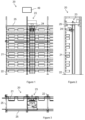
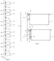
- a store 20 supporting and moving bins 21 open on top and containing products.
- the store 20 has a supporting frame comprising uprights 22 and side members 25.
- a mobile carriage 23 moves in translation along the length of the store 20 on side members 25 whose upper surfaces 32 form rails, the mobile carriage 23 being provided with casters 33 (see figure 10 ).
- the mobile trolley is equipped with a gripping head 39.
- each horizontal conveyor 27 is surrounded by two fixed horizontal supports 28, as illustrated in figure 4 .
- the store 20 comprises at least two horizontal conveyors 27.
- the store 20 comprises, between two successive horizontal conveyors 27, two fixed supports 28.
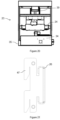
- each horizontal support 28 comprises flat parts 47 provided with teeth fitting into vertical slots forming a rack in the uprights 22 and a crosspiece 26, which extends over the entire length of the magazine, supported by these parts 47.
- each bin 21 has, on the support and conveyor side, on the one hand, and on the carriage side, on the other hand, an edge 42 folded downwards forming an open volume. On the support and conveyor side, this folded edge 42 ensures the gravitational maintenance of the bin 21 on a fixed support 28 or on a conveyor 27.
- each horizontal conveyor 27 comprises flat parts 29 provided with teeth (see in particular the Figures 8 and 9 ) fitting into vertical slots forming a rack in the uprights 22 and a crosspiece 30, which extends over the entire length of the magazine, supported by these parts 29.
- Each crosspiece 30 supports a vertical flat plate 31 on which a toothed belt 19 slides.
- This toothed belt 19, or chain, comprises links coming straddling the edge of the vertical flat plate 31.
- the toothed belt 19 is tensioned by a cable 48 ( figure 5 ) internal to the links.
- a toothed pinion 44 coupled to an output shaft 45 of a rotary motor 43 drives the toothed belt 19.
- a shoe 46 carried by the crosspiece 30 ensures the guidance and sliding of the bins 21 during their movement under the action of the conveyor 27.
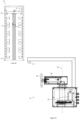
- the store 20 comprises a motorized arm at this end, this motorized arm being configured to take each bin 21 on each conveyor 27 and to connect this bin 21 to a secondary conveyor in order to make it available to an operator or to processing, factory or assembly machines.
- the motorized arm performs a rotation of each bin 21, relative to a vertical axis of rotation, and possibly, a vertical translation, between the conveyor where this bin 21 is initially located up to the secondary conveyor.
- the store 20 further comprises a conveyor for retrieving empty bins 21 up to an empty bin storage area.
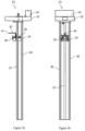
- the mobile carriage 23 comprises, in the upper part, a motor 34 mounted on a frame 35 provided with rollers 33 which roll on the rails 32.
- the frame 35 supports a column 36, on the side opposite the bins 21 and two columns 37 on the side of the bins 21.
- a bin-picking turret 24 moves vertically, which supports a horizontal jack 38 moving the gripping head 39.
- the gripping head 39 has a vertical rectangular shape, with a thickness less than the width of the folded edge 42 of the bins 21, a height substantially equal to the height of the bins 21 and a length substantially equal to that of the bins 21.
- the turret 24 also comprises a support 40 for a camera 41 configured to take an image of the entire contents of a bin 21.
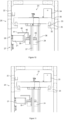
- the turret 24 is first positioned vertically so that the gripping head 39 is entirely below the opening of the internal folded edge 42 of this bin 21, as illustrated in figure 10 . Then the cylinder 38 moves the gripping head 39 to position it below the internal folded edge 42, as illustrated in figure 11 . Then, the turret 24 rises to engage the gripping head 39 in the internal folded edge 42, as illustrated in figure 12 , then to disengage the external folded edge 42, opposite the gripping head 39, from the support 28, as illustrated in figure 13 .
- the ram 38 is then retracted to bring the tank 21 closer to the turret 24, as illustrated in figure 14 .
- Turret 24 is then moved vertically, downwards in figure 14 or upwards when the bin 21 must be positioned on the conveyor 27 located above the support 28 which previously supported this bin 21.
- the jack 38 is actuated to place it there.
- the turret 24 is then lowered, first to engage the outer folded edge 42 of the bin 21 in the toothed belt 19 and then to disengage the gripping head 39 from the inner folded edge 42.
- the jack 38 is retracted.
- the carriage 23 is moved, in the length of the magazine and the turret 24 is moved in the height of the magazine to position the gripping head 39 opposite another bin 21 to be positioned on a conveyor 27.
- the control means 49 comprises, for example, a computer and/or a server accessing and editing databases of products arranged in the different bins 21.
- the control means 49 determines in particular the path of the mobile carriage parallel to the plane of the fixed supports according to the bins to be removed.
- the control means 49 determines the path to be followed by the mobile carriage so that this path successively runs along the different fixed supports carrying said bins to be removed.
- the carriage 23 first processes the first three, which are on the same support 28, then the last two.
- this path runs, in order, through the supports from top to bottom or from bottom to top.
- the processing means 49 determines the position of all the bins 21 conveyed by conveyors 27 and positions a new bin 21 on a conveyor 27 only if the trajectory of this new bin 21 is not likely to cross the trajectory of a bin 21 already present on the conveyor 27 considered.
- the mobile trolley 23 comprises a means for automatically recognizing at least one product present in a bin 21.
- This recognition means comprises, in the embodiment shown, the camera 41 associated with software for recognizing shapes, writing and/or codes.
- the processing of the images provided by the camera 41 may include the location, in two or three dimensions, of the position of a product in a rack. This position can then be used by a gripping member (“picking”) to grasp the product.
- this means of recognition includes a weighing device (not shown) integrated into the trolley 23, the precision of which is finer than the unit weight of the lightest product in the store.
- the magazine 50 comprises rows of bins 21 and conveyors on either side of the movement plane of the turret 51.
- the turret 51 has an additional degree of freedom, compared to the turret 24 since it performs rotations around a vertical rotation axis 52 in order to grip bins 21 on each side of its vertical movement plane.
- a motor 53 rotates the gripping head 39.
- the turret 51 incorporates a precision scale 54 to perform the weight verification of the weight of each bin 21 and the memorization of the stock of products available in the bins 21.
- the camera 41 is mounted on the gripping head 39 to rotate with it.
- the method of providing products present in bins 21 is illustrated, in one of its embodiments 60, in figure 24 .
- control means 49 receives a list of products to be supplied at the outlet by the store 20.
- control means 49 checks, by accessing a database, the presence of the products in the store 20 and determines the position of the bins 21 which comprise these products. If a product is absent in the store 20, the control means 49 returns a message to the stock and order management means.
- the control means 49 determines the fastest path between the bins 21 containing the products to be supplied. In the case where the same product is in several bins 21, the control means 49 chooses from these bins the one that optimizes the speed of supply. In the case where the number of identical products to be supplied requires more than one bin 21 containing such products to be removed, the control means 49 optimizes the choice of bins according to the speed of supply or to maximize the number of bins 21 remaining available, after supply of the products, in the store 20.
- control means 49 controls the positioning of the carriage 23 opposite the next bin 21 to be taken out (see figure 10 ).
- control means 49 controls the raising of the gripping head 39 and the engagement of the internal folded edge 42 of the tray 21 by the gripping head 39 (see figures 11 And 12 ).
- steps 65 and 66 are performed in a single continuous and uniform movement of the gripping head 39.
- control means 49 controls the traction of the tray 21 towards the inside of the store (see figure 14 ).
- control means 49 performs, with the camera 41, the check of the presence of the product to be supplied which must be in the bin 21 and the contents of the bin 21 carried by the trolley 23.
- control means 49 performs, with a weighing member (not shown) integrated into the trolley 23, the weighing of the contents of the bin 21 to determine the number of products present in the bin 21.
- control means 49 performs an estimation of the mechanical deformation of the container 21 under the effect of the weight of its contents. This deformation corresponds to a downward shift of the folded external edge 42 of the container 21.
- the control means 49 determines this deformation with the camera 41, for example by adding to it a pulsed light source to be luminous only for part of the images taken by the camera 41, for example a light-emitting diode (not shown), and by determining the position of the reflection of the light emitted by this light source, on the edges of the bin 21 parallel to the width of the magazine 20. These are the edges of the bin 21 going from the internal folded edge 42 to the external folded edge 42.
- control means 49 controls the vertical movement of the tray 21, up to a conveying height in which the external folded edge 42 of the tray 21 is at a height slightly higher, for example by one centimeter, than the height of the upper part of the toothed belt 19 of the conveyor 27 closest to the support 28 where the tray 21 was taken.
- control means 49 controls the positioning of the external folded edge 42 of the tray 21 carried by the carriage 23 above the toothed belt 19 of this conveyor 27 (see figure 15 ).
- the vertical movement of step 70 and the horizontal movement of step 71 can be combined into a single continuous trajectory.
- control means 49 controls the descent of the gripping head 39 and the engagement of the external folded edge 42 of the tray 21 on the toothed belt 19 (see figure 16 ).
- control means 49 controls the descent of the gripping head 39 and the disengagement of the internal edge 42 of the tray 21 from the gripping head 39 (see figure 17 ). Note that steps 62 and 63 are performed in a single continuous and uniform movement of the gripping head.
- step 74 if the path has not been completely covered, we return to step 64 for the next bin 21 on the path of the cart 23.
- the control means 49 records, in the database, the bins 21 and the products taken out of the store 20.
Landscapes
- Engineering & Computer Science (AREA)
- Mechanical Engineering (AREA)
- Warehouses Or Storage Devices (AREA)
- Specific Conveyance Elements (AREA)
Claims (11)
- Automatisches Robotermagazin (20), dadurch gekennzeichnet, dass es aufweist:- mindestens zwei horizontale feste Stützen (28) zum Halten einer Vielzahl von Behältern (21) mit zu liefernden Produkten in Position, wobei jede horizontale feste Stütze auf einer sogenannten "festen Stützenhöhe" steht,- wenigstens ein Förderband (27), das ausgelegt ist, um wenigstens einen Behälter in horizontaler Bewegung zu tragen, wobei jedes Förderband auf einer Förderhöhe positioniert ist, die sich von jeder festen Stützenhöhe unterscheidet, und- wenigstens einen beweglichen Wagen (23) mit einem Greifkopf (39) und einem Motor (34, 38) zur Bewegung des Greifkopfs, der ausgelegt ist, um einen einzelnen Behälter auf einem Behälterträger aufzunehmen, ihn vertikal bis zu einer Förderhöhe zu bewegen und den bewegten Behälter mechanisch mit dem in dieser Förderhöhe platzierten Förderband zu verbinden, dadurch gekennzeichnet, dass das automatische Robotermagazin wenigstens ein Förderband aufweist, das zwischen zwei horizontalen festen Stützen positioniert ist.
- Magazin (20) nach Anspruch 1, wobei mindestens ein Behälter (21) auf der dem Greifkopf (39) zugewandten Seite einen nach unten gefalteten Rand (42) aufweist, der ein offenes Volumen bildet, und der Greifkopf eine Behälterstütze aufweist, die einen oberen Teil aufweist, der ausgelegt ist, um in die Faltung dieses Randes des Behälters einzudringen.
- Magazin (20) nach einem der Ansprüche 1 oder 2, wobei mindestens ein Behälter (21) auf der der festen Stütze (28) zugewandten Seite einen nach unten gefalteten Rand (42) aufweist, der ein offenes Volumen bildet, und die feste Stütze einen Querträger (26) aufweist, der einen oberen Teil aufweist, der ausgelegt ist, um in die Faltung dieses Randes des Behälters einzudringen.
- Magazin (20) nach einem der Ansprüche 1 bis 3, das wenigstens zwei horizontale Förderbänder (27) und zwischen zwei aufeinanderfolgenden Förderbändern zwei feste Stützen (28) aufweist, wobei jedes horizontale Förderband oben und unten von zwei festen Stützen umgeben ist.
- Magazin (20) nach einem der Ansprüche 1 bis 4, das einen motorisierten Arm am Ende jedes Förderbands (27) aufweist, wo das Förderband jeden Behälter (21) zuführt, wobei der motorisierte Arm ausgelegt ist, um jeden Behälter auf jedem Förderband aufzunehmen, um diesen Behälter mit einem sekundären Förderband zu verbinden.
- Magazin (20) nach Anspruch 5, wobei der motorisierte Arm jeden Behälter dreht.
- Magazin (20) nach einem der Ansprüche 1 bis 6, das ein Steuermittel (49) für den Weg des beweglichen Wagens (23) parallel zur Ebene der festen Stützen (28) umfasst, um in Abhängigkeit von den herauszuführenden Behältern (21) einen Weg zu bestimmen, der von dem beweglichen Wagen zu nehmen ist, wobei der Weg nacheinander den verschiedenen festen Stützen folgt, die die herauszuführenden Behälter tragen.
- Magazin (20) nach einem der Ansprüche 1 bis 7, wobei der bewegliche Wagen (23) ein automatisches Erkennungsmittel für wenigstens ein in einem Behälter (21) vorhandenes Produkt aufweist.
- Magazin (20) nach einem der Ansprüche 1 bis 8, wobei der bewegliche Wagen (23) ein Wiegeorgan aufweist, dessen Genauigkeit genauer ist als das Stückgewicht des leichtesten Produkts im Magazin.
- Magazin (20) nach einem der Ansprüche 1 bis 9, das ferner ein Leerbehälter-Rücknahmeförderband bis zu einem Leerbehälter-Lagerbereich umfasst.
- Verfahren (60) zur Bereitstellung von Produkten in Behältern (21) in einem Magazin (20), das aufweist:- mindestens zwei horizontale feste Stützen (28) zum Halten einer Vielzahl von Behältern in Position, wobei jede horizontale feste Stütze auf einer sogenannten "festen Stützenhöhe" steht,- wenigstens ein Förderband (27), das ausgelegt ist, um wenigstens einen Behälter in horizontaler Bewegung zu tragen, wobei jedes Förderband auf einer Förderhöhe positioniert ist, die sich von jeder festen Stützenhöhe unterscheidet, wobei wenigstens ein Förderband zwischen zwei festen horizontalen Stützen positioniert ist, und- wenigstens einen beweglichen Wagen (23) mit einem Greifkopf (39) und einem Motor (34, 38) zur Bewegung des Greifkopfs,wobei das Verfahren dadurch gekennzeichnet ist, dass es aufweist, durchgeführt von dem beweglichen Wagen:- einen Schritt (64 bis 67) des Aufnehmens eines einzelnen Behälters auf eine Behälterstütze,- einen Schritt (70) des vertikalen Verfahrens des aufgenommenen Behälters bis zu einer Förderhöhe und- einen Schritt (71, 72, 73) der mechanischen Verbindung zwischen dem Behälter und dem Förderband, das sich in dieser Förderhöhe befindet.
Applications Claiming Priority (2)
| Application Number | Priority Date | Filing Date | Title |
|---|---|---|---|
| FR2101190A FR3119616B1 (fr) | 2021-02-08 | 2021-02-08 | Procédé de fourniture automatisé et magasin automatique robotis |
| PCT/EP2022/052346 WO2022167418A1 (fr) | 2021-02-08 | 2022-02-01 | Procédé de fourniture automatisé et magasin automatique robotisé |
Publications (3)
| Publication Number | Publication Date |
|---|---|
| EP4288355A1 EP4288355A1 (de) | 2023-12-13 |
| EP4288355B1 true EP4288355B1 (de) | 2025-01-22 |
| EP4288355C0 EP4288355C0 (de) | 2025-01-22 |
Family
ID=74871693
Family Applications (1)
| Application Number | Title | Priority Date | Filing Date |
|---|---|---|---|
| EP22702736.4A Active EP4288355B1 (de) | 2021-02-08 | 2022-02-01 | Automatisiertes versorgungsverfahren und automatisiertes robotergestütztes lager |
Country Status (8)
| Country | Link |
|---|---|
| US (1) | US20240300739A1 (de) |
| EP (1) | EP4288355B1 (de) |
| JP (1) | JP2024506826A (de) |
| CN (1) | CN116897131B (de) |
| CA (1) | CA3205729A1 (de) |
| ES (1) | ES3023737T3 (de) |
| FR (1) | FR3119616B1 (de) |
| WO (1) | WO2022167418A1 (de) |
Family Cites Families (21)
| Publication number | Priority date | Publication date | Assignee | Title |
|---|---|---|---|---|
| FR2565952B1 (fr) * | 1984-06-14 | 1987-04-24 | Redoute Catalogue | Chariot automoteur de manutention robotise |
| JPS6382203A (ja) * | 1986-09-24 | 1988-04-13 | Kito Corp | 棚積設備 |
| JP3870492B2 (ja) * | 1996-10-07 | 2007-01-17 | 財団法人雑賀技術研究所 | 商品貯留出荷システム |
| US7381022B1 (en) * | 2004-12-18 | 2008-06-03 | Rodney Joe King | Automated 3-dimensional multitasking, stocking, storage, and distribution system |
| US9834378B2 (en) * | 2006-12-22 | 2017-12-05 | Brooks Automation, Inc. | Loader and buffer for reduced lot size |
| WO2012016031A1 (en) * | 2010-07-28 | 2012-02-02 | Par Systems, Inc. | Robotic storage and retrieval systems |
| JP5713203B2 (ja) * | 2012-03-27 | 2015-05-07 | 株式会社ダイフク | 物品収納設備 |
| US9505556B2 (en) * | 2014-09-03 | 2016-11-29 | Ottos Consultants Ltd. | Storage system using lifting mechanism for collecting containers in desired sequence |
| US10442621B2 (en) * | 2014-10-20 | 2019-10-15 | Nelson Mandela Metropolitan University | Warehouse system and transfer vehicle |
| FR3046091B1 (fr) * | 2015-12-24 | 2018-01-05 | Solystic | Equipement de tri postal avec un echangeur de bacs navette en forme de diedre orientes de facon oblique |
| TWI777945B (zh) * | 2016-03-15 | 2022-09-21 | 德商阿莫瓦有限公司 | 用於在高架倉庫中貯存和獲取或者重排貯存品的運輸和轉移系統 |
| JP6766584B2 (ja) * | 2016-10-19 | 2020-10-14 | 株式会社ダイフク | 物品搬送設備 |
| AU2018224834B2 (en) * | 2017-02-24 | 2023-04-27 | Opex Corporation | Automated storage and retrieval systems and methods |
| FR3072371A1 (fr) * | 2017-10-12 | 2019-04-19 | Exotec Solutions | Systeme de stockage et de transport d'objets entreposes dans des rayonnages d'un entrepot |
| WO2019225234A1 (ja) * | 2018-05-23 | 2019-11-28 | 株式会社ダイフク | ピッキングシステム(picking system) |
| EP4588856A1 (de) * | 2018-12-25 | 2025-07-23 | Beijing Geekplus Technology Co., Ltd. | Transferroboter, warenhauslogistiksystem und warentransferverfahren |
| JP7244285B2 (ja) * | 2019-01-29 | 2023-03-22 | 株式会社日立インダストリアルプロダクツ | 物流管理装置、物流管理方法及び物流管理プログラム |
| JP7192723B2 (ja) * | 2019-09-12 | 2022-12-20 | 株式会社ダイフク | 物品搬送設備 |
| CN211768040U (zh) * | 2019-11-13 | 2020-10-27 | 中国建材国际工程集团有限公司 | 一种太阳能电池组件自动存储系统 |
| JP7310854B2 (ja) * | 2021-05-13 | 2023-07-19 | 株式会社ダイフク | 搬送装置 |
| EP4183714A1 (de) * | 2021-11-19 | 2023-05-24 | Fameccanica.Data S.p.A. | Verfahren zur automatischen handhabung von mehreren produktbehältern und entsprechendes system |
-
2021
- 2021-02-08 FR FR2101190A patent/FR3119616B1/fr active Active
-
2022
- 2022-02-01 JP JP2023545211A patent/JP2024506826A/ja active Pending
- 2022-02-01 US US18/260,482 patent/US20240300739A1/en active Pending
- 2022-02-01 WO PCT/EP2022/052346 patent/WO2022167418A1/fr not_active Ceased
- 2022-02-01 ES ES22702736T patent/ES3023737T3/es active Active
- 2022-02-01 CN CN202280013827.9A patent/CN116897131B/zh active Active
- 2022-02-01 EP EP22702736.4A patent/EP4288355B1/de active Active
- 2022-02-01 CA CA3205729A patent/CA3205729A1/fr active Pending
Also Published As
| Publication number | Publication date |
|---|---|
| FR3119616B1 (fr) | 2023-06-02 |
| US20240300739A1 (en) | 2024-09-12 |
| FR3119616A1 (fr) | 2022-08-12 |
| JP2024506826A (ja) | 2024-02-15 |
| ES3023737T3 (en) | 2025-06-03 |
| CN116897131B (zh) | 2026-02-10 |
| CN116897131A (zh) | 2023-10-17 |
| EP4288355A1 (de) | 2023-12-13 |
| WO2022167418A1 (fr) | 2022-08-11 |
| CA3205729A1 (fr) | 2022-08-11 |
| EP4288355C0 (de) | 2025-01-22 |
Similar Documents
| Publication | Publication Date | Title |
|---|---|---|
| EP2999649B1 (de) | Automatisiertes magazin und damit ausgestattete produktionseinheit für fertigprodukte | |
| EP3638607B1 (de) | System zum lagern und transportieren von in den regalen eines lagers gelagerten objekten | |
| EP0169156B1 (de) | Selbstangetriebener Wagen mit Fördereinrichtung durch Roboter | |
| EP0235488B1 (de) | Rechnergesteuertes Kommissionierlager | |
| EP3362379B1 (de) | Kommissiniersystem mit kletternden transportfahrzeugen | |
| FR2652529A1 (fr) | Robot. | |
| EP0761578B1 (de) | Palettiervorrichtung und Palettierverfahren | |
| BE1006857A3 (fr) | Installation pour garnir d'une maconnerie de briques une paroi interieure d'une enceinte. | |
| EP3112294A2 (de) | Lager- und transportvorrichtung | |
| CH619904A5 (de) | ||
| EP4204332B1 (de) | Container-display-station | |
| EP1973819B1 (de) | Verfahren und gruppierstation für einen palettierer | |
| FR2747109A1 (fr) | Magasin de stockage | |
| WO2021176184A1 (fr) | Système et procédé de transfert de contenants dans un entrepôt de stockage | |
| FR2622178A1 (fr) | Dispositif de changement pour produits de grande longueur sur un transporteur a rouleaux | |
| EP4288355A1 (de) | Automatisiertes versorgungsverfahren und automatisiertes robotergestütztes lager | |
| FR2665150A1 (fr) | Dispositif pour le chargement ou le dechargement de caissettes. | |
| WO2018050990A1 (fr) | Dispositif et procédé de groupage et de transfert de caisses palettes de produits triés en lots | |
| FR2892106A1 (fr) | Procede et dispositif de palettisation automatique | |
| FR3099466A1 (fr) | Installation et contenant pour le conditionnement de récipients | |
| WO2012110723A1 (fr) | Outil de manipulation de produits | |
| EP1663826B1 (de) | Handhabungsvorrichtung für kästen und dergleichen | |
| FR3056971A1 (fr) | Deplacement de produits dans une ligne | |
| FR2669312A1 (fr) | Magasin de stockage automatique. | |
| EP4735375A1 (de) | Handhabungsvorrichtung, anordnung mit einer handhabungsvorrichtung und mindestens einem artikel und verfahren zur handhabung solch eines artikels mit solch einer vorrichtung |
Legal Events
| Date | Code | Title | Description |
|---|---|---|---|
| STAA | Information on the status of an ep patent application or granted ep patent |
Free format text: STATUS: UNKNOWN |
|
| STAA | Information on the status of an ep patent application or granted ep patent |
Free format text: STATUS: THE INTERNATIONAL PUBLICATION HAS BEEN MADE |
|
| PUAI | Public reference made under article 153(3) epc to a published international application that has entered the european phase |
Free format text: ORIGINAL CODE: 0009012 |
|
| STAA | Information on the status of an ep patent application or granted ep patent |
Free format text: STATUS: REQUEST FOR EXAMINATION WAS MADE |
|
| 17P | Request for examination filed |
Effective date: 20230706 |
|
| AK | Designated contracting states |
Kind code of ref document: A1 Designated state(s): AL AT BE BG CH CY CZ DE DK EE ES FI FR GB GR HR HU IE IS IT LI LT LU LV MC MK MT NL NO PL PT RO RS SE SI SK SM TR |
|
| DAV | Request for validation of the european patent (deleted) | ||
| DAX | Request for extension of the european patent (deleted) | ||
| GRAP | Despatch of communication of intention to grant a patent |
Free format text: ORIGINAL CODE: EPIDOSNIGR1 |
|
| STAA | Information on the status of an ep patent application or granted ep patent |
Free format text: STATUS: GRANT OF PATENT IS INTENDED |
|
| INTG | Intention to grant announced |
Effective date: 20240618 |
|
| GRAJ | Information related to disapproval of communication of intention to grant by the applicant or resumption of examination proceedings by the epo deleted |
Free format text: ORIGINAL CODE: EPIDOSDIGR1 |
|
| STAA | Information on the status of an ep patent application or granted ep patent |
Free format text: STATUS: REQUEST FOR EXAMINATION WAS MADE |
|
| GRAP | Despatch of communication of intention to grant a patent |
Free format text: ORIGINAL CODE: EPIDOSNIGR1 |
|
| STAA | Information on the status of an ep patent application or granted ep patent |
Free format text: STATUS: GRANT OF PATENT IS INTENDED |
|
| INTC | Intention to grant announced (deleted) | ||
| INTG | Intention to grant announced |
Effective date: 20240902 |
|
| GRAS | Grant fee paid |
Free format text: ORIGINAL CODE: EPIDOSNIGR3 |
|
| GRAA | (expected) grant |
Free format text: ORIGINAL CODE: 0009210 |
|
| STAA | Information on the status of an ep patent application or granted ep patent |
Free format text: STATUS: THE PATENT HAS BEEN GRANTED |
|
| AK | Designated contracting states |
Kind code of ref document: B1 Designated state(s): AL AT BE BG CH CY CZ DE DK EE ES FI FR GB GR HR HU IE IS IT LI LT LU LV MC MK MT NL NO PL PT RO RS SE SI SK SM TR |
|
| REG | Reference to a national code |
Ref country code: GB Ref legal event code: FG4D Free format text: NOT ENGLISH |
|
| REG | Reference to a national code |
Ref country code: CH Ref legal event code: EP |
|
| REG | Reference to a national code |
Ref country code: IE Ref legal event code: FG4D Free format text: LANGUAGE OF EP DOCUMENT: FRENCH |
|
| REG | Reference to a national code |
Ref country code: DE Ref legal event code: R096 Ref document number: 602022009791 Country of ref document: DE |
|
| U01 | Request for unitary effect filed |
Effective date: 20250221 |
|
| U07 | Unitary effect registered |
Designated state(s): AT BE BG DE DK EE FI FR IT LT LU LV MT NL PT RO SE SI Effective date: 20250227 |
|
| U20 | Renewal fee for the european patent with unitary effect paid |
Year of fee payment: 4 Effective date: 20250226 |
|
| REG | Reference to a national code |
Ref country code: ES Ref legal event code: FG2A Ref document number: 3023737 Country of ref document: ES Kind code of ref document: T3 Effective date: 20250603 |
|
| PG25 | Lapsed in a contracting state [announced via postgrant information from national office to epo] |
Ref country code: RS Free format text: LAPSE BECAUSE OF FAILURE TO SUBMIT A TRANSLATION OF THE DESCRIPTION OR TO PAY THE FEE WITHIN THE PRESCRIBED TIME-LIMIT Effective date: 20250422 |
|
| PG25 | Lapsed in a contracting state [announced via postgrant information from national office to epo] |
Ref country code: PL Free format text: LAPSE BECAUSE OF FAILURE TO SUBMIT A TRANSLATION OF THE DESCRIPTION OR TO PAY THE FEE WITHIN THE PRESCRIBED TIME-LIMIT Effective date: 20250122 |
|
| PGFP | Annual fee paid to national office [announced via postgrant information from national office to epo] |
Ref country code: ES Payment date: 20250424 Year of fee payment: 4 |
|
| PG25 | Lapsed in a contracting state [announced via postgrant information from national office to epo] |
Ref country code: IS Free format text: LAPSE BECAUSE OF FAILURE TO SUBMIT A TRANSLATION OF THE DESCRIPTION OR TO PAY THE FEE WITHIN THE PRESCRIBED TIME-LIMIT Effective date: 20250522 Ref country code: NO Free format text: LAPSE BECAUSE OF FAILURE TO SUBMIT A TRANSLATION OF THE DESCRIPTION OR TO PAY THE FEE WITHIN THE PRESCRIBED TIME-LIMIT Effective date: 20250422 |
|
| PG25 | Lapsed in a contracting state [announced via postgrant information from national office to epo] |
Ref country code: HR Free format text: LAPSE BECAUSE OF FAILURE TO SUBMIT A TRANSLATION OF THE DESCRIPTION OR TO PAY THE FEE WITHIN THE PRESCRIBED TIME-LIMIT Effective date: 20250122 |
|
| PG25 | Lapsed in a contracting state [announced via postgrant information from national office to epo] |
Ref country code: GR Free format text: LAPSE BECAUSE OF FAILURE TO SUBMIT A TRANSLATION OF THE DESCRIPTION OR TO PAY THE FEE WITHIN THE PRESCRIBED TIME-LIMIT Effective date: 20250423 |
|
| PG25 | Lapsed in a contracting state [announced via postgrant information from national office to epo] |
Ref country code: SM Free format text: LAPSE BECAUSE OF FAILURE TO SUBMIT A TRANSLATION OF THE DESCRIPTION OR TO PAY THE FEE WITHIN THE PRESCRIBED TIME-LIMIT Effective date: 20250122 |
|
| PG25 | Lapsed in a contracting state [announced via postgrant information from national office to epo] |
Ref country code: MC Free format text: LAPSE BECAUSE OF FAILURE TO SUBMIT A TRANSLATION OF THE DESCRIPTION OR TO PAY THE FEE WITHIN THE PRESCRIBED TIME-LIMIT Effective date: 20250122 |
|
| PG25 | Lapsed in a contracting state [announced via postgrant information from national office to epo] |
Ref country code: CZ Free format text: LAPSE BECAUSE OF FAILURE TO SUBMIT A TRANSLATION OF THE DESCRIPTION OR TO PAY THE FEE WITHIN THE PRESCRIBED TIME-LIMIT Effective date: 20250122 |
|
| PG25 | Lapsed in a contracting state [announced via postgrant information from national office to epo] |
Ref country code: SK Free format text: LAPSE BECAUSE OF FAILURE TO SUBMIT A TRANSLATION OF THE DESCRIPTION OR TO PAY THE FEE WITHIN THE PRESCRIBED TIME-LIMIT Effective date: 20250122 |
|
| PLBE | No opposition filed within time limit |
Free format text: ORIGINAL CODE: 0009261 |
|
| STAA | Information on the status of an ep patent application or granted ep patent |
Free format text: STATUS: NO OPPOSITION FILED WITHIN TIME LIMIT |
|
| REG | Reference to a national code |
Ref country code: CH Ref legal event code: L10 Free format text: ST27 STATUS EVENT CODE: U-0-0-L10-L00 (AS PROVIDED BY THE NATIONAL OFFICE) Effective date: 20251203 |
|
| 26N | No opposition filed |
Effective date: 20251023 |
|
| REG | Reference to a national code |
Ref country code: CH Ref legal event code: U11 Free format text: ST27 STATUS EVENT CODE: U-0-0-U10-U11 (AS PROVIDED BY THE NATIONAL OFFICE) Effective date: 20260331 |
|
| U20 | Renewal fee for the european patent with unitary effect paid |
Year of fee payment: 5 Effective date: 20260227 |
|
| PGFP | Annual fee paid to national office [announced via postgrant information from national office to epo] |
Ref country code: GB Payment date: 20260225 Year of fee payment: 5 |
|
| PGFP | Annual fee paid to national office [announced via postgrant information from national office to epo] |
Ref country code: IE Payment date: 20260224 Year of fee payment: 5 |
|
| PGFP | Annual fee paid to national office [announced via postgrant information from national office to epo] |
Ref country code: TR Payment date: 20260127 Year of fee payment: 5 |
|
| PGFP | Annual fee paid to national office [announced via postgrant information from national office to epo] |
Ref country code: CH Payment date: 20260331 Year of fee payment: 5 |