EP4287280B1 - Punktsteuerungslampe des in-line-typs und lampenstrangstruktur - Google Patents
Punktsteuerungslampe des in-line-typs und lampenstrangstruktur Download PDFInfo
- Publication number
- EP4287280B1 EP4287280B1 EP22204161.8A EP22204161A EP4287280B1 EP 4287280 B1 EP4287280 B1 EP 4287280B1 EP 22204161 A EP22204161 A EP 22204161A EP 4287280 B1 EP4287280 B1 EP 4287280B1
- Authority
- EP
- European Patent Office
- Prior art keywords
- signal
- line
- welding
- parts
- point control
- Prior art date
- Legal status (The legal status is an assumption and is not a legal conclusion. Google has not performed a legal analysis and makes no representation as to the accuracy of the status listed.)
- Active
Links
Images

Classifications
-
- H—ELECTRICITY
- H10—SEMICONDUCTOR DEVICES; ELECTRIC SOLID-STATE DEVICES NOT OTHERWISE PROVIDED FOR
- H10H—INORGANIC LIGHT-EMITTING SEMICONDUCTOR DEVICES HAVING POTENTIAL BARRIERS
- H10H20/00—Individual inorganic light-emitting semiconductor devices having potential barriers, e.g. light-emitting diodes [LED]
- H10H20/80—Constructional details
- H10H20/85—Packages
- H10H20/857—Interconnections, e.g. lead-frames, bond wires or solder balls
-
- H—ELECTRICITY
- H10—SEMICONDUCTOR DEVICES; ELECTRIC SOLID-STATE DEVICES NOT OTHERWISE PROVIDED FOR
- H10W—GENERIC PACKAGES, INTERCONNECTIONS, CONNECTORS OR OTHER CONSTRUCTIONAL DETAILS OF DEVICES COVERED BY CLASS H10
- H10W90/00—Package configurations
-
- H—ELECTRICITY
- H10—SEMICONDUCTOR DEVICES; ELECTRIC SOLID-STATE DEVICES NOT OTHERWISE PROVIDED FOR
- H10H—INORGANIC LIGHT-EMITTING SEMICONDUCTOR DEVICES HAVING POTENTIAL BARRIERS
- H10H20/00—Individual inorganic light-emitting semiconductor devices having potential barriers, e.g. light-emitting diodes [LED]
- H10H20/80—Constructional details
- H10H20/85—Packages
-
- Y—GENERAL TAGGING OF NEW TECHNOLOGICAL DEVELOPMENTS; GENERAL TAGGING OF CROSS-SECTIONAL TECHNOLOGIES SPANNING OVER SEVERAL SECTIONS OF THE IPC; TECHNICAL SUBJECTS COVERED BY FORMER USPC CROSS-REFERENCE ART COLLECTIONS [XRACs] AND DIGESTS
- Y02—TECHNOLOGIES OR APPLICATIONS FOR MITIGATION OR ADAPTATION AGAINST CLIMATE CHANGE
- Y02B—CLIMATE CHANGE MITIGATION TECHNOLOGIES RELATED TO BUILDINGS, e.g. HOUSING, HOUSE APPLIANCES OR RELATED END-USER APPLICATIONS
- Y02B20/00—Energy efficient lighting technologies, e.g. halogen lamps or gas discharge lamps
- Y02B20/30—Semiconductor lamps, e.g. solid state lamps [SSL] light emitting diodes [LED] or organic LED [OLED]
Definitions
- the present invention relates to the technical field of point control lamps, in particular to an in-line type point control lamp and a lamp string structure.
- the existing neon point control lamps are mainly based on LED patch lamp beads, while the traditional in-line LED lamps are 2-wire carrier point control, which transmit signals through the power lines.
- In-line type point control lamps and lamp string structures comprising two power lines and a signal line are disclosed in CN 213599119 U , WO 2016/041381 A1 , CN 114278911 A , CN 112747295 A , and CN 112838153 A .
- the purpose of the present invention is to provide an in-line type point control lamp and a lamp string structure, which solves the technical problem that the traditional point control lamps existed in the prior art transmit signals through power lines, and the stability of the signals transmitted by the power lines will be affected by the power supply, resulting in that the maximum number of lamps having stable signal is currently less, and more lamps cannot be stabilized.
- the present invention provides an in-line type point control lamp according to claim 1.
- any two of the three welding parts are the power connecting parts, and one of the three welding parts is the signal connecting part.
- the present invention provides a lamp string structure comprising the in-line type point control lamp.
- the separately provided signal line is used to transmit the signal, and the power line and the signal line are fixed on the power connecting part and the signal connecting part respectively, compared with the traditional power line transmitting signal, a separate signal line used to transmit the signal can effectively improve the stability and yield of the lamp bead, and solve the technical problem that the traditional point control lamps existed in the prior art transmit signals through power lines, and the stability of the signals transmitted by the power lines will be affected by the power supply, resulting in that the maximum number of lamps having stable signal is currently less, and more lamps cannot be stabilized.
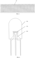
- Reference numerals 100-patch lamp bead; 110-welding plate surface; 111-power line; 112-signal line; 120-bonding pad; 200-in-line LED bracket; 210-power connecting part; 220-signal connecting part; 300-injection molded part.
- orientation or positional relationship indicated by the terms “center”, “upper”, “lower”, “left”, “right”, “vertical”, “horizontal”, “inner” and “outer” etc. are based on the orientation or positional relations as shown in the drawings, or it is the orientation or positional relationship that the product of the invention is usually placed in use, merely for facilitating the description of the present invention and simplifying the description, rather than indicating or implying that related devices or elements have to be in the specific orientation, or configured or operated in a specific orientation, therefore, they should not be construed as limitations on the present invention.
- terms “first”, “second” and “third” etc. are merely for the distinguished description, but should not be construed as indicating or implying importance in relativity.
- connection can be the internal communication between two components.
- the in-line type point control lamp provided by the embodiment comprises a patch lamp bead 100 and an in-line LED bracket 200;
- the patch lamp bead 100 has two power lines 111 and one signal line 112
- the in-line LED bracket 200 has two power connecting parts 210 and one signal connecting part 220, the two power lines 111 are respectively connected to the two power connecting parts 210, and the signal line 112 is connected to the signal connecting part 220.
- the patch lamp bead 100 has two power lines 111 and one signal line 112, the two power lines 111 are divided into a positive line and a negative line, two power lines 111 are respectively connected to the two power connecting parts 210 on the in-line LED bracket 200, the power supply is delivered to the two power lines 111 through the power connecting parts 210, the signal line 112 is connected to the signal connecting part 220 on the in-line LED bracket 200, and the signal is transmitted to the signal line 112 through the signal connecting part 220.
- the LED chip and the control IC in the patch lamp bead 100 can also be directly welded on the in-line LED bracket 200 by traditional lamp-making methods such as die bond and wire bond, and then packaged and injection molded outside.
- the in-line type point control lamp provided by the embodiment comprises: a patch lamp bead 100 and an in-line LED bracket 200; the patch lamp bead 100 has two power lines 111 and one signal line 112, and the in-line LED bracket 200 has two power connecting parts 210 and the one signal connecting part 220, the two power lines 111 are respectively connected to the two power connecting parts 210, and the signal line 112 is connected to the signal connecting part 220.
- the separately provided signal line 112 is used to transmit the signal, and the power line 111 and the signal line 112 are fixed on the power connecting part 210 and the signal connecting part 220 respectively, compared with the traditional power line 111 transmitting signal, a separate signal line 112 used to transmit the signal can effectively improve the stability and yield of the lamp bead, and solve the technical problem that the traditional point control lamps existed in the prior art transmit signals through power lines 111, and the stability of the signals transmitted by the power lines 111 will be affected by the power supply, resulting in that the maximum number of lamps capable of having stable signal is currently less, and more lamps cannot be stabilized.
- the patch lamp bead 100 in the in-line type point control lamp provided by the present invention has a welding plate surface 110, and two power connecting parts 210 and the one signal connecting part 220 are all welded on the welding plate surface 110.
- the welding plate surface 110 is installed on the backside of the patch lamp bead 100, two power lines 111 and one signal line 112 are all electrically connected to the welding plate surface 110, after the power connecting parts 210 and the signal connecting part 220 are welded on the welding plate surface 110, the power lines 111 are connected with the power connecting parts 210, and the signal line 112 is connected with signal connecting part 220.
- the in-line LED bracket 200 comprises three welding parts; three welding parts are arranged side by side in parallel, and three welding parts are all welded on the welding plate surface 110; any two of three welding parts are power connecting parts 210, and one of three welding parts is the signal connecting part 220.
- the in-line LED bracket 200 has three welding parts, and the three welding parts are arranged side by side, wherein any two welding parts can be used as the power connecting parts 210, and the other welding part is the signal connecting part 220.
- the top of each welding part has a welding point, and the three welding points are divided into positive welding point, negative welding point and signal welding point.
- two power lines 111 are respectively located on two sides of the signal line 112; the welding parts located on two sides are two power connecting parts 210, and the welding part located in a middle of the two welding parts is the signal connecting part 220.
- the two power lines 111 on the patch lamp bead 100 are located on two sides of the signal line 112, respectively, and the signal line 112 is located between the two power lines 111, correspondingly, for the welding parts on the in-line LED bracket 200, the welding parts located on two sides are correspondingly provided as the power connecting parts 210, and the welding part located between the two welding parts is the signal connecting part 220, which corresponds to the patch lamp bead 100.
- the welding plate surface 110 has three bonding pads 120, and two power connecting parts 210 and the one signal connecting part 220 are respectively welded on the three bonding pads 120; and three bonding pads 120 are respectively electrically connected with two power lines 111 and one signal line 112.
- the patch lamp bead 100 is welded on the in-line LED bracket 200 by using the bonding pads 120, so that the power connecting parts 210 are connected with the power lines 111, and the signal connecting part 220 is connected with the signal line 112.
- the in-line type point control lamp further comprises an injection molded part 300; and the patch lamp bead 100 is provided in the injection molded part 300, and the power connecting parts 210 extend into the injection molded part 300 and are connected to the power lines 111, and the signal connecting part 220 passes through the injection molded part 300 and is connected to the signal line 112.
- an injection molded part 300 is formed outside the patch lamp bead 100, and the patch lamp bead 100 is wrapped by using the injection molded part 300 to form a point control lamp.
- the lamp string structure provided in this embodiment includes the in-line type point control light.
Landscapes
- Non-Portable Lighting Devices Or Systems Thereof (AREA)
Claims (6)
- Inline-Punktsteuerungsleuchte aufweisend: eine Patch-Lampen-Sicke (100) und eine Inline-LED-Halterung (200);wobei die Patch-Lampen-Sicke (100) zwei Stromleitungen (111) und eine Signalleitung (112) hat, und die Inline-LED-Halterung (200) zwei Stromverbindungsteile (210) und ein Signalverbindungsteil (220) hat, wobei die beiden Stromleitungen (111) jeweils mit den beiden Stromverbindungsteilen (210) verbunden sind und die Signalleitung (112) mit dem Signalverbindungsteil (220) verbunden ist,die Patch-Lampen-Sicke (100) eine Schweißplattenoberfläche (110) aufweist, und die beiden Stromverbindungsteile (210) und das eine Signalverbindungsteil (220) alle auf der Schweißplattenoberfläche (110) verschweißt sind,die Schweißplattenoberfläche (110) drei Fügeflächen (120) aufweist und die beiden Stromverbindungsteile (210) und das eine Signalverbindungsteil (220) jeweils auf die drei Fügeflächen (120) geschweißt sind.die drei Fügeflächen (120) jeweils mit den zwei Stromleitungen (111) und einer Signalleitung (112) elektrisch verbunden sind, unddie Schweißplattenoberfläche (110) sich auf der Rückseite der Patch-Lampen-Sicke (100) befindet.
- Inline-Punktsteuerungslampe nach Anspruch 1,wobei die Inline-LED-Halterung (200) drei Schweißteile aufweist; unddie drei Schweißteile parallel nebeneinander angeordnet sind und die drei Schweißteile alle auf der Schweißplattenoberfläche (110) verschweißt sind.
- Inline-Punktsteuerungsleuchte nach Anspruch 2,
wobei zwei der drei Schweißteile die Stromverbindungsteile (210) sind und eines der drei Schweißteile das Signalverbindungsteil (220) ist. - Inline-Punktsteuerungslampe nach Anspruch 2,wobei die beiden Stromleitungen (111) jeweils auf zwei Seiten der Signalleitung (112) angeordnet sind; undSchweißteile, die sich auf zwei Seiten befinden, die beiden Stromverbindungsteile (210) sind, und ein Schweißteil, das sich in der Mitte der beiden Schweißteile befindet, das Signalverbindungsteil (220) ist.
- Inline-Punktsteuerungslampe nach Anspruch 1,wobei die Inline-Punktsteuerungsleuchte des Weiteren ein Spritzgussteil (300) umfasst; unddie Patch-Lampen-Sicke (100) in dem Spritzgussteil (300) vorgesehen ist, und die Stromverbindungsteile (210) sich in das Spritzgussteil (300) erstrecken und mit den Stromleitungen (111) verbunden sind, und das Signalverbindungsteil (220) durch das Spritzgussteil (300) hindurchgeht und mit der Signalleitung (112) verbunden ist.
- Lampenstrangstruktur, dadurch gekennzeichnet, dass sie die Inline-Punktsteuerungslampe nach einem der Ansprüche 1-5 aufweist.
Applications Claiming Priority (1)
| Application Number | Priority Date | Filing Date | Title |
|---|---|---|---|
| CN202221358681.5U CN217382611U (zh) | 2022-06-01 | 2022-06-01 | 直插式点控灯及灯串结构 |
Publications (3)
| Publication Number | Publication Date |
|---|---|
| EP4287280A1 EP4287280A1 (de) | 2023-12-06 |
| EP4287280B1 true EP4287280B1 (de) | 2024-09-18 |
| EP4287280C0 EP4287280C0 (de) | 2024-09-18 |
Family
ID=83089131
Family Applications (1)
| Application Number | Title | Priority Date | Filing Date |
|---|---|---|---|
| EP22204161.8A Active EP4287280B1 (de) | 2022-06-01 | 2022-10-27 | Punktsteuerungslampe des in-line-typs und lampenstrangstruktur |
Country Status (3)
| Country | Link |
|---|---|
| US (2) | USD984001S1 (de) |
| EP (1) | EP4287280B1 (de) |
| CN (1) | CN217382611U (de) |
Families Citing this family (3)
| Publication number | Priority date | Publication date | Assignee | Title |
|---|---|---|---|---|
| TWD230942S (zh) * | 2023-03-15 | 2024-04-21 | 日商松下控股股份有限公司 (日本) | 紅外線感測器 |
| CN220551866U (zh) | 2023-07-05 | 2024-03-01 | 上犹县嘉亿灯饰制品有限公司 | 点控灯和灯串 |
| USD1124426S1 (en) * | 2024-06-18 | 2026-04-28 | Creeled, Inc. | Light-emitting diode package |
Family Cites Families (36)
| Publication number | Priority date | Publication date | Assignee | Title |
|---|---|---|---|---|
| US3458779A (en) * | 1967-11-24 | 1969-07-29 | Gen Electric | Sic p-n junction electroluminescent diode with a donor concentration diminishing from the junction to one surface and an acceptor concentration increasing in the same region |
| US3774086A (en) * | 1972-09-25 | 1973-11-20 | Gen Electric | Solid state lamp having visible-emitting phosphor at edge of infrated-emitting element |
| US3962719A (en) * | 1974-12-05 | 1976-06-08 | Plastronics, Inc. | Mounting pad and semiconductor encapsulation device combination |
| USD277955S (en) | 1981-10-30 | 1985-03-12 | Stanley Electric Co., Ltd. | Light-emitting diode semiconductor chip with leads |
| USD278049S (en) * | 1981-10-30 | 1985-03-19 | Stanley Electric Co., Ltd. | Light-emitting diode semiconductor chip with leads |
| USD278048S (en) * | 1981-10-30 | 1985-03-19 | Stanley Electric Co., Ltd. | Light-emitting diode semiconductor chip with leads |
| JPH07281619A (ja) * | 1994-04-04 | 1995-10-27 | Rohm Co Ltd | Ledランプ、およびその基板への取付け構造 |
| US5659222A (en) * | 1996-02-27 | 1997-08-19 | Illumination Technology, Inc. | Vacuum sealed incandescent lamp with improved filament support structure |
| US6577073B2 (en) * | 2000-05-31 | 2003-06-10 | Matsushita Electric Industrial Co., Ltd. | Led lamp |
| USD480160S1 (en) | 2001-05-29 | 2003-09-30 | Omron Corporation | Light-emitting diode |
| USD476296S1 (en) * | 2001-09-06 | 2003-06-24 | Sharp Kabushiki Kaisha | Semiconductor device |
| USD482666S1 (en) | 2001-11-30 | 2003-11-25 | Nichia Corporation | Light emitting diode (LED) |
| TWD113350S1 (zh) * | 2003-02-13 | 2006-10-11 | 夏普股份有限公司 | 紅外線感應器 |
| US20040245539A1 (en) * | 2003-06-06 | 2004-12-09 | Tien-Yu Chen | Light-emitting diode light string |
| USD564107S1 (en) * | 2005-05-30 | 2008-03-11 | Lee Hor | LED micro bulb |
| US7775687B2 (en) * | 2006-02-20 | 2010-08-17 | Nichia Corporation | Light emitting device |
| TWD124441S1 (zh) | 2006-03-29 | 2008-08-21 | 首爾半導體股份有限公司 | 發光二極體(led) |
| USD572209S1 (en) | 2006-08-04 | 2008-07-01 | Nichia Corporation | Light emitting diode |
| USD576967S1 (en) | 2006-12-13 | 2008-09-16 | Seoul Semiconductor Co., Ltd. | Light emitting diode |
| US20080274377A1 (en) * | 2007-05-02 | 2008-11-06 | Cheng-Chen Lin | Resin artcraft with electric conduction function and method of manufacturing the same |
| USD627494S1 (en) * | 2010-03-01 | 2010-11-16 | Hsin-Wei Wu | LED bulb |
| USD660258S1 (en) | 2011-05-04 | 2012-05-22 | Epistar Corporation | Light emitting diode |
| USD689219S1 (en) | 2012-05-29 | 2013-09-03 | Ce Lighting Ltd. | LED lamp |
| CN102891236B (zh) * | 2012-09-13 | 2015-12-16 | 惠州雷曼光电科技有限公司 | Led及其封装方法 |
| CN204144256U (zh) * | 2014-09-15 | 2015-02-04 | 东莞市永林电子有限公司 | 三只脚引脚式触发闪灯led |
| USD838867S1 (en) | 2016-10-26 | 2019-01-22 | Sheen Rise Co., Ltd. | Light emitting diode |
| JP6637569B1 (ja) | 2018-10-17 | 2020-01-29 | 浜松ホトニクス株式会社 | フラッシュランプ及びフラッシュランプの製造方法 |
| CN110033711B (zh) * | 2019-03-28 | 2024-07-26 | 深圳市晶泓科技有限公司 | 一种透明led显示屏 |
| USD861966S1 (en) | 2019-05-14 | 2019-10-01 | Shenzhen Yachang Technology Co., Ltd. | LED light |
| USD965536S1 (en) | 2019-07-30 | 2022-10-04 | Defond Electech Co., Ltd. | Touch LED component |
| CN213599119U (zh) * | 2020-12-30 | 2021-07-02 | 深圳市逸飞光电科技有限公司 | 灯珠以及灯串 |
| USD935644S1 (en) | 2021-01-07 | 2021-11-09 | Fan Zhang | Light with faceted LED |
| CN214147795U (zh) * | 2021-01-11 | 2021-09-07 | 黄萍 | 信号串联的移位寄存贴片发光二极管灯珠用印制电路板 |
| CN112747295B (zh) * | 2021-01-25 | 2024-10-01 | 崇义县精亿灯饰制品有限公司 | 灯珠支架及灯具 |
| CN112838153A (zh) * | 2021-02-02 | 2021-05-25 | 东莞市华彩威科技有限公司 | 一种led灯串、制造方法以及用于该led灯串中的led器件 |
| CN114278911A (zh) * | 2021-12-10 | 2022-04-05 | 佛山市彩立德光电技术有限公司 | 一种级联型led灯串线路板连接结构 |
-
2022
- 2022-06-01 CN CN202221358681.5U patent/CN217382611U/zh active Active
- 2022-10-12 US US29/856,275 patent/USD984001S1/en active Active
- 2022-10-27 EP EP22204161.8A patent/EP4287280B1/de active Active
- 2022-11-29 US US18/059,802 patent/US11817539B1/en active Active
Also Published As
| Publication number | Publication date |
|---|---|
| USD984001S1 (en) | 2023-04-18 |
| EP4287280A1 (de) | 2023-12-06 |
| CN217382611U (zh) | 2022-09-06 |
| US20230395769A1 (en) | 2023-12-07 |
| US11817539B1 (en) | 2023-11-14 |
| EP4287280C0 (de) | 2024-09-18 |
Similar Documents
| Publication | Publication Date | Title |
|---|---|---|
| EP4287280B1 (de) | Punktsteuerungslampe des in-line-typs und lampenstrangstruktur | |
| US6297598B1 (en) | Single-side mounted light emitting diode module | |
| EP1873566A2 (de) | Lichtemittierende Diode mit Lichtleiteranordnung | |
| TW200516752A (en) | Lead frame and semiconductor package with the lead frame | |
| EP3772874B1 (de) | Intelligente lampe | |
| KR20220001954U (ko) | Led 라이트 스트링, 제조 방법 및 led 라이트 스트링에 사용되는 led 소자 | |
| CN207818609U (zh) | 一种倒装芯片固晶结构 | |
| KR100270756B1 (ko) | 반도체장치 | |
| CN216872005U (zh) | 一种led封装器件 | |
| CN212322993U (zh) | 一种减小探测器中跨阻放大器输出信号线寄生电感的结构 | |
| CN211828767U (zh) | 一种显示模组及显示屏 | |
| CN219642838U (zh) | 一种内置ic的led支架结构 | |
| CN216450635U (zh) | Led固晶结构及led支架 | |
| CN218069850U (zh) | 一种适合皮线灯生产的内置ic幻彩灯珠 | |
| CN219800845U (zh) | 一种内置ic驱动rgbww的led支架结构 | |
| CN217562564U (zh) | 一种三色led芯片的封装结构 | |
| CN214797453U (zh) | 一种提高led可靠性的支架结构 | |
| CN204424308U (zh) | 一种led支架及led灯珠 | |
| CN103809250A (zh) | 光学引擎总成及使用该光学引擎总成的收发器 | |
| CN212323000U (zh) | Led封装器件 | |
| CN220526944U (zh) | 一种led封装结构及皮线灯 | |
| CN210866165U (zh) | 一种芯片支架 | |
| CN219202384U (zh) | 一种高度集成的sip指纹模组 | |
| CN209843699U (zh) | 一种芯片封装结构 | |
| CN211236357U (zh) | 一种光发射接收组件封装 |
Legal Events
| Date | Code | Title | Description |
|---|---|---|---|
| PUAI | Public reference made under article 153(3) epc to a published international application that has entered the european phase |
Free format text: ORIGINAL CODE: 0009012 |
|
| STAA | Information on the status of an ep patent application or granted ep patent |
Free format text: STATUS: EXAMINATION IS IN PROGRESS |
|
| 17P | Request for examination filed |
Effective date: 20221027 |
|
| AK | Designated contracting states |
Kind code of ref document: A1 Designated state(s): AL AT BE BG CH CY CZ DE DK EE ES FI FR GB GR HR HU IE IS IT LI LT LU LV MC ME MK MT NL NO PL PT RO RS SE SI SK SM TR |
|
| GRAP | Despatch of communication of intention to grant a patent |
Free format text: ORIGINAL CODE: EPIDOSNIGR1 |
|
| STAA | Information on the status of an ep patent application or granted ep patent |
Free format text: STATUS: GRANT OF PATENT IS INTENDED |
|
| RAP3 | Party data changed (applicant data changed or rights of an application transferred) |
Owner name: SHANGYOU JIAYI LIGHTING PRODUCT CO., LTD. |
|
| RIN1 | Information on inventor provided before grant (corrected) |
Inventor name: HE, YAOWEN |
|
| INTG | Intention to grant announced |
Effective date: 20240514 |
|
| GRAS | Grant fee paid |
Free format text: ORIGINAL CODE: EPIDOSNIGR3 |
|
| GRAA | (expected) grant |
Free format text: ORIGINAL CODE: 0009210 |
|
| STAA | Information on the status of an ep patent application or granted ep patent |
Free format text: STATUS: THE PATENT HAS BEEN GRANTED |
|
| AK | Designated contracting states |
Kind code of ref document: B1 Designated state(s): AL AT BE BG CH CY CZ DE DK EE ES FI FR GB GR HR HU IE IS IT LI LT LU LV MC ME MK MT NL NO PL PT RO RS SE SI SK SM TR |
|
| REG | Reference to a national code |
Ref country code: GB Ref legal event code: FG4D |
|
| REG | Reference to a national code |
Ref country code: CH Ref legal event code: EP |
|
| REG | Reference to a national code |
Ref country code: IE Ref legal event code: FG4D |
|
| REG | Reference to a national code |
Ref country code: DE Ref legal event code: R096 Ref document number: 602022006188 Country of ref document: DE |
|
| U01 | Request for unitary effect filed |
Effective date: 20241016 |
|
| U07 | Unitary effect registered |
Designated state(s): AT BE BG DE DK EE FI FR IT LT LU LV MT NL PT RO SE SI Effective date: 20241104 |
|
| PG25 | Lapsed in a contracting state [announced via postgrant information from national office to epo] |
Ref country code: NO Free format text: LAPSE BECAUSE OF FAILURE TO SUBMIT A TRANSLATION OF THE DESCRIPTION OR TO PAY THE FEE WITHIN THE PRESCRIBED TIME-LIMIT Effective date: 20241218 |
|
| PG25 | Lapsed in a contracting state [announced via postgrant information from national office to epo] |
Ref country code: GR Free format text: LAPSE BECAUSE OF FAILURE TO SUBMIT A TRANSLATION OF THE DESCRIPTION OR TO PAY THE FEE WITHIN THE PRESCRIBED TIME-LIMIT Effective date: 20241219 |
|
| PG25 | Lapsed in a contracting state [announced via postgrant information from national office to epo] |
Ref country code: HR Free format text: LAPSE BECAUSE OF FAILURE TO SUBMIT A TRANSLATION OF THE DESCRIPTION OR TO PAY THE FEE WITHIN THE PRESCRIBED TIME-LIMIT Effective date: 20240918 |
|
| PG25 | Lapsed in a contracting state [announced via postgrant information from national office to epo] |
Ref country code: RS Free format text: LAPSE BECAUSE OF FAILURE TO SUBMIT A TRANSLATION OF THE DESCRIPTION OR TO PAY THE FEE WITHIN THE PRESCRIBED TIME-LIMIT Effective date: 20241218 |
|
| PG25 | Lapsed in a contracting state [announced via postgrant information from national office to epo] |
Ref country code: RS Free format text: LAPSE BECAUSE OF FAILURE TO SUBMIT A TRANSLATION OF THE DESCRIPTION OR TO PAY THE FEE WITHIN THE PRESCRIBED TIME-LIMIT Effective date: 20241218 Ref country code: NO Free format text: LAPSE BECAUSE OF FAILURE TO SUBMIT A TRANSLATION OF THE DESCRIPTION OR TO PAY THE FEE WITHIN THE PRESCRIBED TIME-LIMIT Effective date: 20241218 Ref country code: HR Free format text: LAPSE BECAUSE OF FAILURE TO SUBMIT A TRANSLATION OF THE DESCRIPTION OR TO PAY THE FEE WITHIN THE PRESCRIBED TIME-LIMIT Effective date: 20240918 Ref country code: GR Free format text: LAPSE BECAUSE OF FAILURE TO SUBMIT A TRANSLATION OF THE DESCRIPTION OR TO PAY THE FEE WITHIN THE PRESCRIBED TIME-LIMIT Effective date: 20241219 |
|
| U20 | Renewal fee for the european patent with unitary effect paid |
Year of fee payment: 3 Effective date: 20250123 |
|
| PG25 | Lapsed in a contracting state [announced via postgrant information from national office to epo] |
Ref country code: IS Free format text: LAPSE BECAUSE OF FAILURE TO SUBMIT A TRANSLATION OF THE DESCRIPTION OR TO PAY THE FEE WITHIN THE PRESCRIBED TIME-LIMIT Effective date: 20250118 |
|
| PG25 | Lapsed in a contracting state [announced via postgrant information from national office to epo] |
Ref country code: SM Free format text: LAPSE BECAUSE OF FAILURE TO SUBMIT A TRANSLATION OF THE DESCRIPTION OR TO PAY THE FEE WITHIN THE PRESCRIBED TIME-LIMIT Effective date: 20240918 |
|
| PG25 | Lapsed in a contracting state [announced via postgrant information from national office to epo] |
Ref country code: ES Free format text: LAPSE BECAUSE OF FAILURE TO SUBMIT A TRANSLATION OF THE DESCRIPTION OR TO PAY THE FEE WITHIN THE PRESCRIBED TIME-LIMIT Effective date: 20240918 |
|
| PG25 | Lapsed in a contracting state [announced via postgrant information from national office to epo] |
Ref country code: PL Free format text: LAPSE BECAUSE OF FAILURE TO SUBMIT A TRANSLATION OF THE DESCRIPTION OR TO PAY THE FEE WITHIN THE PRESCRIBED TIME-LIMIT Effective date: 20240918 Ref country code: CZ Free format text: LAPSE BECAUSE OF FAILURE TO SUBMIT A TRANSLATION OF THE DESCRIPTION OR TO PAY THE FEE WITHIN THE PRESCRIBED TIME-LIMIT Effective date: 20240918 |
|
| PG25 | Lapsed in a contracting state [announced via postgrant information from national office to epo] |
Ref country code: SK Free format text: LAPSE BECAUSE OF FAILURE TO SUBMIT A TRANSLATION OF THE DESCRIPTION OR TO PAY THE FEE WITHIN THE PRESCRIBED TIME-LIMIT Effective date: 20240918 |
|
| PG25 | Lapsed in a contracting state [announced via postgrant information from national office to epo] |
Ref country code: MC Free format text: LAPSE BECAUSE OF FAILURE TO SUBMIT A TRANSLATION OF THE DESCRIPTION OR TO PAY THE FEE WITHIN THE PRESCRIBED TIME-LIMIT Effective date: 20240918 |
|
| PLBE | No opposition filed within time limit |
Free format text: ORIGINAL CODE: 0009261 |
|
| STAA | Information on the status of an ep patent application or granted ep patent |
Free format text: STATUS: NO OPPOSITION FILED WITHIN TIME LIMIT |
|
| 26N | No opposition filed |
Effective date: 20250619 |
|
| PG25 | Lapsed in a contracting state [announced via postgrant information from national office to epo] |
Ref country code: IE Free format text: LAPSE BECAUSE OF NON-PAYMENT OF DUE FEES Effective date: 20241027 |
|
| REG | Reference to a national code |
Ref country code: CH Ref legal event code: U11 Free format text: ST27 STATUS EVENT CODE: U-0-0-U10-U11 (AS PROVIDED BY THE NATIONAL OFFICE) Effective date: 20251101 |
|
| U20 | Renewal fee for the european patent with unitary effect paid |
Year of fee payment: 4 Effective date: 20251027 |
|
| PGFP | Annual fee paid to national office [announced via postgrant information from national office to epo] |
Ref country code: CH Payment date: 20251101 Year of fee payment: 4 |
|
| PG25 | Lapsed in a contracting state [announced via postgrant information from national office to epo] |
Ref country code: CY Free format text: LAPSE BECAUSE OF FAILURE TO SUBMIT A TRANSLATION OF THE DESCRIPTION OR TO PAY THE FEE WITHIN THE PRESCRIBED TIME-LIMIT; INVALID AB INITIO Effective date: 20221027 |
|
| PG25 | Lapsed in a contracting state [announced via postgrant information from national office to epo] |
Ref country code: HU Free format text: LAPSE BECAUSE OF FAILURE TO SUBMIT A TRANSLATION OF THE DESCRIPTION OR TO PAY THE FEE WITHIN THE PRESCRIBED TIME-LIMIT; INVALID AB INITIO Effective date: 20221027 |