EP4286193B1 - Hybridgetriebe für ein fahrzeug - Google Patents
Hybridgetriebe für ein fahrzeug Download PDFInfo
- Publication number
- EP4286193B1 EP4286193B1 EP23182829.4A EP23182829A EP4286193B1 EP 4286193 B1 EP4286193 B1 EP 4286193B1 EP 23182829 A EP23182829 A EP 23182829A EP 4286193 B1 EP4286193 B1 EP 4286193B1
- Authority
- EP
- European Patent Office
- Prior art keywords
- transmission
- power electronics
- longitudinal direction
- electric machine
- hybrid
- Prior art date
- Legal status (The legal status is an assumption and is not a legal conclusion. Google has not performed a legal analysis and makes no representation as to the accuracy of the status listed.)
- Active
Links
Images

Classifications
-
- B—PERFORMING OPERATIONS; TRANSPORTING
- B60—VEHICLES IN GENERAL
- B60K—ARRANGEMENT OR MOUNTING OF PROPULSION UNITS OR OF TRANSMISSIONS IN VEHICLES; ARRANGEMENT OR MOUNTING OF PLURAL DIVERSE PRIME-MOVERS IN VEHICLES; AUXILIARY DRIVES FOR VEHICLES; INSTRUMENTATION OR DASHBOARDS FOR VEHICLES; ARRANGEMENTS IN CONNECTION WITH COOLING, AIR INTAKE, GAS EXHAUST OR FUEL SUPPLY OF PROPULSION UNITS IN VEHICLES
- B60K6/00—Arrangement or mounting of plural diverse prime-movers for mutual or common propulsion, e.g. hybrid propulsion systems comprising electric motors and internal combustion engines
- B60K6/20—Arrangement or mounting of plural diverse prime-movers for mutual or common propulsion, e.g. hybrid propulsion systems comprising electric motors and internal combustion engines the prime-movers consisting of electric motors and internal combustion engines, e.g. HEVs
- B60K6/22—Arrangement or mounting of plural diverse prime-movers for mutual or common propulsion, e.g. hybrid propulsion systems comprising electric motors and internal combustion engines the prime-movers consisting of electric motors and internal combustion engines, e.g. HEVs characterised by apparatus, components or means specially adapted for HEVs
- B60K6/36—Arrangement or mounting of plural diverse prime-movers for mutual or common propulsion, e.g. hybrid propulsion systems comprising electric motors and internal combustion engines the prime-movers consisting of electric motors and internal combustion engines, e.g. HEVs characterised by apparatus, components or means specially adapted for HEVs characterised by the transmission gearings
-
- B—PERFORMING OPERATIONS; TRANSPORTING
- B60—VEHICLES IN GENERAL
- B60K—ARRANGEMENT OR MOUNTING OF PROPULSION UNITS OR OF TRANSMISSIONS IN VEHICLES; ARRANGEMENT OR MOUNTING OF PLURAL DIVERSE PRIME-MOVERS IN VEHICLES; AUXILIARY DRIVES FOR VEHICLES; INSTRUMENTATION OR DASHBOARDS FOR VEHICLES; ARRANGEMENTS IN CONNECTION WITH COOLING, AIR INTAKE, GAS EXHAUST OR FUEL SUPPLY OF PROPULSION UNITS IN VEHICLES
- B60K6/00—Arrangement or mounting of plural diverse prime-movers for mutual or common propulsion, e.g. hybrid propulsion systems comprising electric motors and internal combustion engines
- B60K6/20—Arrangement or mounting of plural diverse prime-movers for mutual or common propulsion, e.g. hybrid propulsion systems comprising electric motors and internal combustion engines the prime-movers consisting of electric motors and internal combustion engines, e.g. HEVs
- B60K6/22—Arrangement or mounting of plural diverse prime-movers for mutual or common propulsion, e.g. hybrid propulsion systems comprising electric motors and internal combustion engines the prime-movers consisting of electric motors and internal combustion engines, e.g. HEVs characterised by apparatus, components or means specially adapted for HEVs
- B60K6/38—Arrangement or mounting of plural diverse prime-movers for mutual or common propulsion, e.g. hybrid propulsion systems comprising electric motors and internal combustion engines the prime-movers consisting of electric motors and internal combustion engines, e.g. HEVs characterised by apparatus, components or means specially adapted for HEVs characterised by the driveline clutches
- B60K6/387—Actuated clutches, i.e. clutches engaged or disengaged by electric, hydraulic or mechanical actuating means
-
- B—PERFORMING OPERATIONS; TRANSPORTING
- B60—VEHICLES IN GENERAL
- B60K—ARRANGEMENT OR MOUNTING OF PROPULSION UNITS OR OF TRANSMISSIONS IN VEHICLES; ARRANGEMENT OR MOUNTING OF PLURAL DIVERSE PRIME-MOVERS IN VEHICLES; AUXILIARY DRIVES FOR VEHICLES; INSTRUMENTATION OR DASHBOARDS FOR VEHICLES; ARRANGEMENTS IN CONNECTION WITH COOLING, AIR INTAKE, GAS EXHAUST OR FUEL SUPPLY OF PROPULSION UNITS IN VEHICLES
- B60K6/00—Arrangement or mounting of plural diverse prime-movers for mutual or common propulsion, e.g. hybrid propulsion systems comprising electric motors and internal combustion engines
- B60K6/20—Arrangement or mounting of plural diverse prime-movers for mutual or common propulsion, e.g. hybrid propulsion systems comprising electric motors and internal combustion engines the prime-movers consisting of electric motors and internal combustion engines, e.g. HEVs
- B60K6/22—Arrangement or mounting of plural diverse prime-movers for mutual or common propulsion, e.g. hybrid propulsion systems comprising electric motors and internal combustion engines the prime-movers consisting of electric motors and internal combustion engines, e.g. HEVs characterised by apparatus, components or means specially adapted for HEVs
- B60K6/40—Arrangement or mounting of plural diverse prime-movers for mutual or common propulsion, e.g. hybrid propulsion systems comprising electric motors and internal combustion engines the prime-movers consisting of electric motors and internal combustion engines, e.g. HEVs characterised by apparatus, components or means specially adapted for HEVs characterised by the assembly or relative disposition of components
-
- B—PERFORMING OPERATIONS; TRANSPORTING
- B60—VEHICLES IN GENERAL
- B60K—ARRANGEMENT OR MOUNTING OF PROPULSION UNITS OR OF TRANSMISSIONS IN VEHICLES; ARRANGEMENT OR MOUNTING OF PLURAL DIVERSE PRIME-MOVERS IN VEHICLES; AUXILIARY DRIVES FOR VEHICLES; INSTRUMENTATION OR DASHBOARDS FOR VEHICLES; ARRANGEMENTS IN CONNECTION WITH COOLING, AIR INTAKE, GAS EXHAUST OR FUEL SUPPLY OF PROPULSION UNITS IN VEHICLES
- B60K6/00—Arrangement or mounting of plural diverse prime-movers for mutual or common propulsion, e.g. hybrid propulsion systems comprising electric motors and internal combustion engines
- B60K6/20—Arrangement or mounting of plural diverse prime-movers for mutual or common propulsion, e.g. hybrid propulsion systems comprising electric motors and internal combustion engines the prime-movers consisting of electric motors and internal combustion engines, e.g. HEVs
- B60K6/42—Arrangement or mounting of plural diverse prime-movers for mutual or common propulsion, e.g. hybrid propulsion systems comprising electric motors and internal combustion engines the prime-movers consisting of electric motors and internal combustion engines, e.g. HEVs characterised by the architecture of the hybrid electric vehicle
- B60K6/48—Parallel type
-
- B—PERFORMING OPERATIONS; TRANSPORTING
- B60—VEHICLES IN GENERAL
- B60K—ARRANGEMENT OR MOUNTING OF PROPULSION UNITS OR OF TRANSMISSIONS IN VEHICLES; ARRANGEMENT OR MOUNTING OF PLURAL DIVERSE PRIME-MOVERS IN VEHICLES; AUXILIARY DRIVES FOR VEHICLES; INSTRUMENTATION OR DASHBOARDS FOR VEHICLES; ARRANGEMENTS IN CONNECTION WITH COOLING, AIR INTAKE, GAS EXHAUST OR FUEL SUPPLY OF PROPULSION UNITS IN VEHICLES
- B60K6/00—Arrangement or mounting of plural diverse prime-movers for mutual or common propulsion, e.g. hybrid propulsion systems comprising electric motors and internal combustion engines
- B60K6/20—Arrangement or mounting of plural diverse prime-movers for mutual or common propulsion, e.g. hybrid propulsion systems comprising electric motors and internal combustion engines the prime-movers consisting of electric motors and internal combustion engines, e.g. HEVs
- B60K6/42—Arrangement or mounting of plural diverse prime-movers for mutual or common propulsion, e.g. hybrid propulsion systems comprising electric motors and internal combustion engines the prime-movers consisting of electric motors and internal combustion engines, e.g. HEVs characterised by the architecture of the hybrid electric vehicle
- B60K6/48—Parallel type
- B60K2006/4833—Step up or reduction gearing driving generator, e.g. to operate generator in most efficient speed range
-
- B—PERFORMING OPERATIONS; TRANSPORTING
- B60—VEHICLES IN GENERAL
- B60K—ARRANGEMENT OR MOUNTING OF PROPULSION UNITS OR OF TRANSMISSIONS IN VEHICLES; ARRANGEMENT OR MOUNTING OF PLURAL DIVERSE PRIME-MOVERS IN VEHICLES; AUXILIARY DRIVES FOR VEHICLES; INSTRUMENTATION OR DASHBOARDS FOR VEHICLES; ARRANGEMENTS IN CONNECTION WITH COOLING, AIR INTAKE, GAS EXHAUST OR FUEL SUPPLY OF PROPULSION UNITS IN VEHICLES
- B60K6/00—Arrangement or mounting of plural diverse prime-movers for mutual or common propulsion, e.g. hybrid propulsion systems comprising electric motors and internal combustion engines
- B60K6/20—Arrangement or mounting of plural diverse prime-movers for mutual or common propulsion, e.g. hybrid propulsion systems comprising electric motors and internal combustion engines the prime-movers consisting of electric motors and internal combustion engines, e.g. HEVs
- B60K6/50—Architecture of the driveline characterised by arrangement or kind of transmission units
- B60K6/52—Driving a plurality of drive axles, e.g. four-wheel drive
-
- B—PERFORMING OPERATIONS; TRANSPORTING
- B60—VEHICLES IN GENERAL
- B60Y—INDEXING SCHEME RELATING TO ASPECTS CROSS-CUTTING VEHICLE TECHNOLOGY
- B60Y2400/00—Special features of vehicle units
- B60Y2400/61—Arrangements of controllers for electric machines, e.g. inverters
-
- Y—GENERAL TAGGING OF NEW TECHNOLOGICAL DEVELOPMENTS; GENERAL TAGGING OF CROSS-SECTIONAL TECHNOLOGIES SPANNING OVER SEVERAL SECTIONS OF THE IPC; TECHNICAL SUBJECTS COVERED BY FORMER USPC CROSS-REFERENCE ART COLLECTIONS [XRACs] AND DIGESTS
- Y02—TECHNOLOGIES OR APPLICATIONS FOR MITIGATION OR ADAPTATION AGAINST CLIMATE CHANGE
- Y02T—CLIMATE CHANGE MITIGATION TECHNOLOGIES RELATED TO TRANSPORTATION
- Y02T10/00—Road transport of goods or passengers
- Y02T10/60—Other road transportation technologies with climate change mitigation effect
- Y02T10/62—Hybrid vehicles
Definitions
- the invention relates to a hybrid transmission for a vehicle according to the type defined in the preamble of claim 1.
- Hybrid transmissions for vehicles are basically known from the state of the art.
- the main aim is always to achieve the most efficient and compact transmission design possible.
- the EN 10 2010 002 746 A1 the integration of an electric machine including its power electronics into a hybrid transmission.
- the design is such that the electric machine is used in a so-called inline arrangement, i.e. coaxial to the transmission main shaft.
- the EN 11 2014 001 112 T5 A hybrid transmission is known in which a hydraulic control and an electric machine are arranged in, or on, a housing of the hybrid transmission.
- the hybrid transmission for a vehicle it is initially such that it comprises a transmission input shaft running in a transverse direction and at least one countershaft arranged parallel thereto.
- a clutch device is present, which can preferably be designed as a double clutch, as a separating clutch or as a combination thereof.
- the structure comprises two countershafts when designed as a double clutch, and one countershaft when designed as a pure separating clutch.
- a differential gear is provided, which has a differential input gear, the axis of rotation of which is arranged parallel to the transmission input shaft, i.e. the direction referred to as the transverse direction in the structure according to the invention.
- An electric machine with a stator and a rotor is also arranged such that the rotor axis of rotation runs parallel to the transmission input shaft.
- a transmission control unit, via which electronic transmission control is achieved, is provided. Seen in a longitudinal direction, which is perpendicular to the transverse direction already mentioned is arranged, the differential input gear, the transmission input shaft and the transmission control unit are arranged one after the other in the order mentioned.
- the transmission control unit is an electronic control unit by means of which an actuator for switching units of a gear set of the hybrid transmission is controlled.
- the actuator can be a hydraulic actuator or an electromechanical actuator or a mixture of both in a manner known per se.
- the transmission control unit controls, for example, solenoid valves and a hydraulic pump.
- the transmission control unit controls, for example, servomotors.
- the transmission control unit is also advantageously designed to control a lubrication and cooling system of the gear set in a manner known per se.
- the transmission control unit can also advantageously be designed to control a cooling system of the electric machine.
- At least part of the power electronics for the electric machine is arranged in a vertical direction, which is arranged perpendicular to both the transverse direction and the longitudinal direction, and is advantageously arranged adjacent to the transmission control unit.
- This part of the power electronics comprises the largest part of the same in terms of construction, but in any case a circuit board of an inverter.
- This arrangement creates an extremely efficient and compact structure. This enables a high level of system integration, which enables a correspondingly high power density of the hybrid transmission according to the invention.
- such a structure, which can be designed to be correspondingly compact can be ideally adapted to the installation space requirements when designing the vehicle in terms of packaging.
- the electric machine is arranged vertically adjacent to and above a hydraulic transmission control and longitudinally overlapping it.
- This allows ideal use to be made of an installation space in which the gear set of the hybrid transmission with the transmission input shaft and the at least one countershaft, the electric machine, the control unit and the hydraulic transmission control are arranged, with this hydraulic transmission control preferably being arranged longitudinally adjacent to the control unit.
- the hydraulic transmission control includes at least switching valves, for example solenoid valves, which are used to switch gear selectors of the gear set.
- the hydraulic transmission control advantageously also includes valves which are used to control a lubrication and cooling system of the hybrid transmission.
- the hydraulic transmission control is electrically connected to the transmission control unit.
- Power electronics refers to a known electronic unit assigned to the electrical machine. The power electronics are used to control the electrical machine.
- the gear set of the hybrid transmission refers to a part of the hybrid transmission that is used to create different gears, i.e. different gear ratios.
- the gear set includes at least the input shaft, the countershafts and the gears and shift units arranged coaxially to these shafts.
- the compact hybrid transmission with high power density enables an optimized structure for the vehicle body in terms of crash requirements, which provides another decisive advantage in such a vehicle with the hybrid transmission given the high additional masses caused in particular by the traction battery.
- a parallel arrangement of a rotatably mounted element to a direction means that an axis of rotation of the rotatably mounted element is arranged parallel to the direction.
- a parallel arrangement of two rotatably mounted elements means that the axes of rotation of the two elements are arranged parallel.
- a coaxial arrangement of two other rotatably mounted elements means that the other two elements have the same axis of rotation.
- the fact that the clutch device is arranged coaxially to the transmission input shaft means that rotatably mounted clutch discs or clutch plates are arranged coaxially to the transmission input shaft.
- a direct current connection for the power electronics is arranged vertically above the rotor rotation axis and longitudinally between the axis of rotation of the differential input gear and the rotor axis of rotation.
- At least one part of the power electronics is arranged vertically above the transmission control unit when used as intended.
- the transmission control unit can be arranged in the transmission oil, and the power electronics are then located above the transmission control unit, preferably adjacent to the electric machine when viewed in the longitudinal direction.
- part of the power electronics extends in the longitudinal direction and is arranged vertically above the electric machine.
- the power electronics are essentially L-shaped when looking at the structure in the transverse direction and are located partly adjacent to, preferably above, the transmission control unit and partly above the electric machine, so that the power electronics partially enclose it and can thus be integrated even more efficiently into the existing installation space.
- the power electronics can be arranged in the longitudinal direction and/or the transverse direction, at least partially overlapping the transmission control unit. This saves further installation space by, depending on the dimensions of the Transmission control unit on the one hand and the power electronics on the other hand, these are arranged overlapping in one or the other direction.
- a circuit board of an inverter of the power electronics is arranged vertically adjacent and longitudinally parallel to a circuit board of the transmission control unit.
- This arrangement with adjacent circuit boards which according to an extremely advantageous development of this idea are spaced apart by less than 20 mm in the longitudinal direction and are preferably even arranged in alignment in the vertical direction, creates a very efficient use of the installation space in the longitudinal direction, in that these two circuit boards are preferably arranged directly adjacent to one another, for example in a common installation space for the control, which is preferably open within a transmission housing of the hybrid transmission.
- the electric machine is designed so that the rotor rotation axis runs parallel to the transmission input shaft, i.e. in the transverse direction of the structure. According to a very advantageous development, it is arranged in the longitudinal direction between the transmission input shaft and the power electronics, whereby, as already indicated above, according to an advantageous embodiment, the electric machine is arranged in the longitudinal direction adjacent to at least part of the power electronics, whereby this part comprises at least the circuit board, while another part can be arranged running in the longitudinal direction.
- This comprises, for example, a connector plug for the DC voltage connection and an intermediate circuit capacitor, to name just a few preferred elements for the arrangement in this area.
- an alternating current connection which connects the electric machine and the power electronics to one another, is arranged vertically below the rotor rotation axis.
- it can be arranged at the bottom of the circuit board of the inverter on the one hand and the electric machine on the other, so that the rest of the inverter circuit board extends upwards in the vertical direction and thus in the longitudinal direction next to the electric machine.
- the transmission housing has a cover which is arranged in the longitudinal direction on the side of the transmission control unit and the power electronics facing away from the transmission input shaft.
- the power electronics or at least the essential part with the circuit board of the inverter and the transmission control unit for the electrical control of the gear set are therefore located under the cover of the transmission housing, which otherwise includes the differential input gear, the transmission input shaft, the at least one countershaft, the electric machine and the hydraulic transmission control.
- This arrangement makes the power electronics and the transmission control unit relatively easy to access.
- this cover is then at the front in the direction of travel of the vehicle, i.e. in the longitudinal direction, so that the cover is accessible from the front of the vehicle.
- a hybrid transmission designated as a whole with 1, for a vehicle not shown here can be seen.
- three directions are shown schematically.
- a longitudinal direction x and a vertical direction z span the Figure 1 Perpendicular to this, extending into the drawing plane, is a transverse direction y.
- the structure together with other components can be seen rotated again, so that the longitudinal direction x is out of the plane of the sheet and the representation plane is spanned by the transverse direction y and the vertical direction z.
- the hybrid transmission 1 is now partially located in a transmission housing designated 2.
- the hybrid transmission 1 comprises an electric machine 3 and a differential transmission, of which a differential input gear 4 is shown here.
- a transmission which comprises a transmission input shaft 5 and, in the embodiment shown here, two countershafts 6.
- This coupling device 7 is for the Figure 1 In the case shown, it is designed as a double clutch, which can also include a separating clutch. As will be explained later, a design with a separating clutch alone would also be conceivable.
- the dual clutch transmission shown here is connected to the clutch device 7, as shown in the illustration of the Figure 2 can be seen, is connected to an internal combustion engine 8.
- Connected in the sense of the invention generally means that the connection is formed indirectly, via a device (not shown here) for cancelling and damping torsional vibrations, for example a dual-mass flywheel or the like.
- a device for cancelling and damping torsional vibrations, for example a dual-mass flywheel or the like.
- the electric machine 3 is arranged in a so-called side-by-side arrangement with a gear set of the hybrid transmission 1.
- the side-by-side arrangement of the electric machine 3 means that the rotor rotation axis 9 is arranged axially parallel and offset to the transmission input shaft 5 and also axially parallel and offset to the countershafts 6.
- the electric machine 3 can be coupled to a gear or a toothing of the hybrid transmission 1, for example, via a spur gear pair (not shown here) or via a chain drive.
- This toothing can be, for example, an external toothing on a disk carrier of the clutch device or a gear in the gear set of the transmission, so that the electric machine 4 can transmit its power for example to the transmission input shaft or in particular to one of the countershafts 6.
- a hydraulic transmission control 10 adjacent to the transmission input shaft 5 and, furthermore, a transmission control unit 11 which takes over the electrical control of the gear set of the hybrid transmission 1.
- a power electronics unit 12 is arranged in the vertical direction z above and adjacent to the transmission control unit 11. This comprises at least one circuit board of an inverter, designated 13, which is connected to the electric machine 3 via a three-phase alternating current connection 14.
- an intermediate circuit capacitor 15 is shown schematically in the power electronics unit 12.
- the power electronics 12 and thus ultimately the electric machine 3 are connected to a traction battery (not shown here) of the vehicle equipped with the hybrid transmission 1 via a direct current connection 16, which is led out of the transmission housing 2 in an area designated 17.
- the gear housing 2 has in the longitudinal direction x in the illustration of the Figure 1 on the right a housing cover 18, which is preferably arranged at the front in the direction of travel. This makes the structure easily accessible with regard to the power electronics 12 and the transmission control unit 11, while the direct current connection 16, which is led out of the transmission housing 2 in the area designated 17, is shifted to the rear accordingly in order to offer the highest possible safety in the event of a crash of a vehicle equipped with the hybrid transmission 1.
- this area 17 for realizing the direct current connection on the housing 2 is located in the longitudinal direction x between the rotor axis 9 of the electric machine 3 and a rotation axis 19 of the differential input gear 4 and is thus so far away in the longitudinal direction x both from the front of the transmission housing 2 with its cover 18 and from the opposite side, a high level of safety is ensured in the event of a crash.
- the power electronics 12 essentially comprise a primary section with the circuit board 13 of the inverter, which is arranged in the longitudinal direction x between the cover 18 and the electric machine 3, so that the arrangement of the AC connection below the rotor rotation axis 9 of the electric machine 3 ensures that the installation space next to the electric machine 3 is ideally utilized.
- Another part, e.g. with the DC connection 16 and the intermediate circuit capacitor 15, of the power electronics 12 can extend in the longitudinal direction x and is arranged in the vertical direction z adjacent to the electric machine, so that it is partially enclosed by the power electronics 12.
- the hydraulic transmission control 10 is arranged overlapping the electric machine 3 between the transmission control unit 11 and the gear set with its input shaft 5 and the countershafts 6, so that it can interact directly with the corresponding components within the transmission, which also makes the structure compact and very efficient in terms of the required cable lengths.
- a circuit board 20 of the transmission control unit 11 is arranged adjacent to the circuit board 13 of the inverter in the vertical direction Z and parallel to it in the longitudinal direction x. In the longitudinal direction x, these should preferably be less than 20 mm apart. Ideally, they are arranged one behind the other in alignment along the vertical direction z.
- an optional recess designated 22 can be seen, in the area of which outside the transmission housing 2, particularly preferably components of the steering of the vehicle could be arranged.
- the optional recess 22 is advantageously arranged between the axis of rotation 19 of the differential input gear 4 and the transmission control unit 11, viewed in the longitudinal direction x.
- the coupling device 7 is designed as a pure separating coupling. Unlike the structure in the illustration of the Figure 1 This means that no dual-clutch transmission with two countershafts 6 is controlled, but rather a simple hybrid transmission with a modified gear set with an input shaft 5 and a single countershaft 6, via which the differential input gear 4 is driven accordingly.
- the structure could, for example, be implemented in the form of a simple automated manual transmission, which is hybridized accordingly with the electric machine 3. This is arranged in the side-by-side arrangement with the modified gear set in the hybrid transmission 1 as described above.
- the crucial structure of the integrated control with the power electronics 12 and the transmission control unit 11 is identical to the previously described embodiment.
Landscapes
- Engineering & Computer Science (AREA)
- Chemical & Material Sciences (AREA)
- Combustion & Propulsion (AREA)
- Transportation (AREA)
- Mechanical Engineering (AREA)
- Hybrid Electric Vehicles (AREA)
- Arrangement Of Transmissions (AREA)
- Mechanical Operated Clutches (AREA)
- General Details Of Gearings (AREA)
- Structure Of Transmissions (AREA)
- Motor Power Transmission Devices (AREA)
Description
- Die Erfindung betrifft ein Hybridgetriebe für ein Fahrzeug nach der im Oberbegriff von Anspruch 1 näher definierten Art.
- Hybridgetriebe für Fahrzeuge sind prinzipiell aus dem Stand der Technik bekannt. Dabei geht es in Wesentlichen immer darum, einen möglichst effizienten und kompakten Aufbau des Getriebes zu erreichen. So beschreibt beispielsweise die
DE 10 2010 002 746 A1 die Integration einer elektrischen Maschine samt ihrer Leistungselektronik in ein Hybridgetriebe. Der Aufbau ist dabei so, dass die elektrische Maschine in einer sogenannten Inline-Anordnung eingesetzt wird, also koaxial zur Getriebehauptwelle. - Aus dem weiteren Stand der Technik in Form der
DE 10 2018 002 167 B3 ist ein Doppelkupplungsgetriebe für ein Kraftfahrzeug bekannt. Dabei ist es so, dass zur Einsparung von Bauraum eine elektrohydraulische Steuereinheit im Ölraum angeordnet ist. Da diese Elektrohydraulik einerseits aus einer Elektronik und andererseits aus der hydraulischen Getriebesteuerung besteht, ist hier also auch das Getriebesteuergerät, worunter im Allgemeinen die elektrische Steuerung des Getriebes zu verstehen ist, in den Aufbau des Getriebes, hier also in das Getriebegehäuse, mit integriert. - Ferner ist aus der
DE 11 2014 001 112 T5 ein Hybridgetriebe bekannt, bei dem eine hydraulische Steuerung sowie eine elektrische Maschine in, beziehungsweise an, einem Gehäuse des Hybridgetriebes angeordnet sind. - Aus der
DE 11 2009 000 022 B4 ist ein Hybridgetriebe bekannt, bei dem eine Leistungselektronik einer elektrischen Maschine und ein Getriebe zusammen in einem integrierten Gehäuse angeordnet sind. - Aus der gattungsgemäßen
DE 10 2015 014 096 A1 ist ein Hybridgetriebe bekannt, bei welchem eine elektrische Maschine hinsichtlich einer Hochrichtung benachbart und oberhalb einer hydraulischen Getriebesteuerung angeordnet ist. Aus derEP 1 000 790 A2 ist eine Antriebseinheit bekannt, bei welcher eine Leistungselektronik oberhalb einer elektrischen Maschine angeordnet ist. - Trotz dieser Schriften gibt es weiterhin ein großes Optimierungspotenzial hinsichtlich einer möglichst kompakten Bauweise von Hybridgetrieben, insbesondere in ihrer axialen Richtung entlang der Getriebehauptwelle, um eine möglichst kompakte Bauweise und eine hohe Leistungsdichte zu erreichen.
- Dementsprechend ist es die Aufgabe der hier vorliegenden Erfindung, ein Hybridgetriebe für ein Fahrzeug mit den Merkmalen im Oberbegriff des Anspruchs 1 dahingehend zu verbessern, dass dieses noch kompakter realisiert werden kann.
- Erfindungsgemäß wird dies durch ein Hybridgetriebe mit den Merkmalen im Anspruch 1, und hier insbesondere im kennzeichnenden Teil von Anspruch 1, erreicht. Vorteilhafte Ausgestaltungen und Weiterbildungen des erfindungsgemäßen Hybridgetriebes ergeben sich aus den hiervon abhängigen Unteransprüchen.
- Bei dem Hybridgetriebe für ein Fahrzeug ist es wie im Stand der Technik zunächst bekannt so, dass dieses eine in einer Querrichtung verlaufende Getriebeeingangswelle und zumindest eine parallel dazu angeordnete Vorgelegewelle umfasst. Außerdem ist eine Kupplungseinrichtung vorhanden, welche vorzugsweise als Doppelkupplung, als Trennkupplung oder als Kombination hieraus ausgebildet sein kann. Insbesondere umfasst der Aufbau bei der Ausbildung als Doppelkupplung zwei Vorgelegewellen, bei der Ausgestaltung als reine Trennkupplung eine Vorgelegewelle. Des Weiteren ist ein Differentialgetriebe vorgesehen, welches ein Differentialeingangszahnrad aufweist, dessen Drehachse parallel zur Getriebeeingangswelle, also der beim erfindungsgemäßen Aufbau als Querrichtung bezeichneten Richtung, angeordnet ist. Eine elektrische Maschine mit einem Stator und einem Rotor ist ebenfalls so angeordnet, dass die Rotordrehachse parallel zur Getriebeeingangswelle verläuft. Ein Getriebesteuergerät, über welches eine elektronische Getriebesteuerung erzielt wird, ist vorgesehen. In einer Längsrichtung gesehen, welche senkrecht zu der bereits genannten Querrichtung angeordnet ist, ist das Differentialeingangszahnrad, die Getriebeeingangswelle und das Getriebesteuergerät dabei in der genannten Reihenfolge nacheinander angeordnet.
- Mit dem Getriebesteuergerät ist ein elektronisches Steuergerät gemeint, mittels welchem eine Aktuatorik für Schalteinheiten eines Radsatzes des Hybridgetriebes angesteuert werden. Bei der Aktuatorik kann es sich auf an sich bekannte Weise um eine hydraulische Aktuatorik oder um eine elektromechanische Aktuatorik oder um eine Mischform aus beidem handeln. Im Falle der hydraulischen Aktuatorik steuert das Getriebesteuergerät zum Beispiel Magnetventile und eine Hydraulikpumpe. Im Falle der elektromechanischen Aktuatorik steuert das Getriebesteuergerät zum Beispiel Stellmotoren. Vorteilhaft ist das Getriebesteuergerät ferner dazu ausgebildet, auf an sich bekannte Weise ein Schmier- und Kühlsystem des Radsatzes zu steuern. Vorteilhaft kann das Getriebesteuergerät auch dazu ausgebildet sein, ein Kühlsystem der elektrischen Maschine zu steuern.
- Ferner ist es auf an sich bekannte Weise so, dass in einer Hochrichtung, welche senkrecht sowohl zu der Querrichtung als auch zu der Längsrichtung angeordnet ist, zumindest ein Teil einer Leistungselektronik für die elektrische Maschine angeordnet ist, und zwar vorteilhaft benachbart zu dem Getriebesteuergerät. Dieser Teil der Leistungselektronik umfasst dabei den konstruktiv größten Teil derselben, in jedem Fall aber eine Platine eines Inverters. Diese Anordnung schafft einen außerordentlich effizienten und kompakten Aufbau. Somit ist eine hohe Systemintegration möglich, welche eine entsprechend hohe Leistungsdichte des erfindungsgemäßen Hybridgetriebes ermöglicht. Außerdem lässt sich ein solcher Aufbau, welcher entsprechend kompakt gestaltet werden kann, hinsichtlich des Packagings ideal an die Bauraumanforderungen bei der Konstruktion des Fahrzeugs anpassen.
- Ferner ist auf an sich bekannte Weise vorgesehen, dass die elektrische Maschine in der Hochrichtung benachbart und oberhalb einer hydraulischen Getriebesteuerung und in Längsrichtung überlappend zu dieser angeordnet ist. So lässt sich ein Bauraum, in welchem der Radsatz des Hybridgetriebes mit der Getriebeeingangswelle und der wenigstens einen Vorgelegewelle, die elektrische Maschine, das Steuergerät und die hydraulische Getriebesteuerung angeordnet sind, ideal nutzen, wobei vorzugsweise diese hydraulische Getriebesteuerung in Längsrichtung benachbart zu dem Steuergerät angeordnet ist.
- Die hydraulische Getriebesteuerung umfasst dabei zumindest Schaltventile, zum Beispiel Magnetventile, die zur Schaltung von Gangstellern des Radsatzes eingesetzt sind. Vorteilhaft umfasst die hydraulische Getriebesteuerung auch Ventile, die für eine Steuerung eines Schmier- und Kühlsystems des Hybridgetriebes eingesetzt sind. Die hydraulische Getriebesteuerung ist elektrisch mit dem Getriebesteuergerät verbunden.
- Mit der Leistungselektronik ist eine an sich bekannte, der elektrischen Maschine zugeordnete Elektronikeinheit gemeint. Die Leistungselektronik dient einer Steuerung der elektrischen Maschine.
- Mit dem Radsatz des Hybridgetriebes ist ein Teil des Hybridgetriebes gemeint, der zu einer Bildung unterschiedlicher Getriebegänge, das heißt unterschiedlicher Getriebeübersetzungen, dient. Der Radsatz umfasst zumindest die Eingangswelle, die Vorgelegewellen sowie jeweils koaxial zu diesen Wellen angeordnete Zahnräder und Schalteinheiten.
- Das kompakt bauende Hybridgetriebe mit hoher Leistungsdichte ermöglicht für den Fahrzeugrohbau eine optimierte Struktur hinsichtlich der Crashanforderungen, was bei den hohen, insbesondere durch die Traktionsbatterie bedingten Zusatzmassen, in einem solchen Fahrzeug mit dem Hybridgetriebe einen weiteren entscheidenden Vorteil ermöglicht.
- Unter einer parallelen Anordnung eines drehbar gelagerten Elementes zu einer Richtung ist zu verstehen, dass eine Drehachse des drehbar gelagerten Elementes parallel zu der Richtung angeordnet ist. Entsprechend ist unter einer parallelen Anordnung zweier drehbar gelagerter Elemente zu verstehen, dass die Drehachsen der beiden Elemente parallel angeordnet sind. Unter einer koaxialen Anordnung zweier anderer drehbar gelagerter Elemente ist zu verstehen, dass die beiden anderen Elemente die gleiche Drehachse haben. Darunter, dass die Kupplungseinrichtung koaxial zu der Getriebeeingangswelle angeordnet ist, ist zu verstehen, dass drehbar gelagerte Kupplungsscheiben oder Kupplungslamellen koaxial zu der Getriebeeingangswelle angeordnet sind.
- Erfindungsgemäß ist ein Gleichstromanschluss für die Leistungselektronik in Hochrichtung oberhalb der Rotordrehachse und in Längsrichtung zwischen der Drehachse des Differentialeingangszahnrads und der Rotordrehachse angeordnet. Insbesondere bei einem Quereinbau des Hybridgetriebes in einem Fahrzeug, bei welchem die hier als Querrichtung definierte Richtung der Querrichtung des Fahrzeugs, die Längsrichtung der Längsrichtung des Fahrzeugs und die Hochrichtung einer Hochrichtung des Fahrzeugs entspricht, kann dies von entscheidendem Vorteil sein, da der Gleichstromanschluss so aus dem Frontbereich des Fahrzeugs zurück verlagert wird und somit für den Fall eines eventuellen Unfalls in einem relativ gut geschützten Bereich liegt. Der Gleichstromanschluss ist typischerweise an dem Getriebegehäuse des Getriebes, welches zumindest die Leistungselektronik, das Getriebesteuergerät, die hydraulische Getriebesteuerung und den Radsatz aufnimmt, angeordnet. Hierdurch ist sie in einem relativ sicheren Bereich für den potenziellen Crashfall angeordnet.
- Gemäß einer außerordentlich günstigen Weiterbildung des erfindungsgemäßen Hybridgetriebes ist der zumindest eine Teil der Leistungselektronik dabei im bestimmungsgemäßen Einsatz in der Hochrichtung oberhalb des Getriebesteuergeräts angeordnet. Dieser Aufbau ermöglicht eine weitere Optimierung. Das Getriebesteuergerät kann dabei im Getriebeöl angeordnet sein, die Leistungselektronik liegt dann oberhalb des Getriebesteuergeräts vorzugsweise benachbart zu der elektrischen Maschine in Längsrichtung gesehen.
- Gemäß einer weiteren sehr günstigen Ausgestaltung des erfindungsgemäßen Hybridgetriebes kann es außerdem vorgesehen sein, dass ein Teil der Leistungselektronik sich in Längsrichtung erstreckt und in Hochrichtung oberhalb der elektrischen Maschine angeordnet ist. Die Leistungselektronik ist in diesem Fall also beim Blick in der Querrichtung auf den Aufbau im Wesentlichen L-förmig ausgebildet und liegt teilweise benachbart, vorzugsweise oberhalb, des Getriebesteuergeräts und teilweise oberhalb der elektrischen Maschine, sodass die Leistungselektronik diese teilweise umschließt und somit noch effizienter in den bestehenden Bauraum integriert werden kann.
- Die Leistungselektronik kann dabei gemäß einer außerordentlich günstigen Weiterbildung des erfindungsgemäßen Hybridgetriebes in der Längsrichtung und/oder der Querrichtung zumindest teilweise überlappend zu dem Getriebesteuergerät angeordnet werden. Hierdurch lässt sich weiterer Bauraum einsparen, indem, je nach Abmessung des Getriebesteuergeräts einerseits und der Leistungselektronik andererseits, diese in die eine oder andere der Richtungen überlappend angeordnet werden.
- Eine weitere außerordentlich günstige Ausgestaltung sieht es ferner vor, dass eine Platine eines Inverters der Leistungselektronik in der Hochrichtung benachbart und in der Längsrichtung parallel zu einer Platine des Getriebesteuergeräts angeordnet ist. Diese Anordnung mit benachbarten Platinen, welche gemäß einer außerordentlich günstigen Weiterbildung dieser Idee in der Längsrichtung weniger als 20 mm beabstandet sind und bevorzugt sogar in der Hochrichtung fluchtend angeordnet sind, schafft eine sehr effiziente Nutzung des Bauraums in der Längsrichtung, indem diese beiden Platinen vorzugsweise direkt aneinander anschließend beispielsweise in einem gemeinsamen Bauraum für die Steuerung, welcher bevorzugt offen innerhalb eines Getriebegehäuses des Hybridgetriebes liegt, angeordnet sind.
- Die elektrische Maschine ist dabei, wie oben bereits erwähnt, so ausgebildet, dass die Rotordrehachse parallel zur Getriebeeingangswelle, also in der Querrichtung des Aufbaus verläuft. Gemäß einer sehr vorteilhaften Weiterbildung ist sie in Längsrichtung zwischen der Getriebeeingangswelle und der Leistungselektronik angeordnet, wobei, wie oben bereits angedeutet, gemäß einer vorteilhaften Ausgestaltung die elektrische Maschine in Längsrichtung benachbart zu zumindest einem Teil der Leistungselektronik angeordnet ist, wobei dieser Teil zumindest die Platine umfasst, während ein weiterer Teil in Längsrichtung verlaufend angeordnet sein kann. Dieser umfasst beispielsweise einen Anschlussstecker für den Gleichspannungsanschluss und einen Zwischenkreiskondensator, um nur einige bevorzugte Elemente für die Anordnung in diesem Bereich zu nennen.
- Ein Wechselstromanschluss, welcher die elektrische Maschine und die Leistungselektronik miteinander verbindet, ist dabei gemäß einer sehr vorteilhaften Weiterbildung des erfindungsgemäßen Hybridgetriebes in der Hochrichtung unterhalb der Rotordrehachse angeordnet. Er kann im bestimmungsgemäßen Einsatz unten an der Platine des Inverters einerseits und der elektrischen Maschine andererseits angeordnet werden, sodass die restliche Platine des Inverters sich in der Hochrichtung nach oben und damit in der Längsrichtung neben der elektrischen Maschine erstreckt.
- Eine besonders vorteilhafte Weiterbildung des erfindungsgemäßen Hybridgetriebes sieht es außerdem vor, dass das Getriebegehäuse einen Deckel aufweist, welcher in der Längsrichtung auf der der Getriebeeingangswelle abgewandten Seite des Getriebesteuergeräts und der Leistungselektronik angeordnet ist. Die Leistungselektronik oder zumindest der wesentliche Teil mit der Platine des Inverters und das Getriebesteuergerät für die elektrische Steuerung des Radsatzes liegen also unter dem Deckel des Getriebegehäuses, welches ansonsten das Differentialeingangszahnrad, die Getriebeeingangswelle, die mindestens eine Vorgelegewelle, die elektrische Maschine und die hydraulische Getriebesteuerung mit umfasst. Durch diese Anordnung sind die Leistungselektronik und das Getriebesteuergerät relativ einfach zugänglich. Bei einem oben schon angesprochenen Quereinbau des Hybridgetriebes in einem Fahrzeug liegt dieser Deckel dann in Fahrtrichtung des Fahrzeugs, also in der Längsrichtung, vorne, sodass der Deckel von der Front des Fahrzeugs her zugänglich ist.
- Weitere vorteilhafte Ausgestaltungen des erfindungsgemäßen Hybridgetriebes ergeben sich auch aus den Ausführungsbeispielen, welche nachfolgend unter Bezugnahme auf die Figuren näher beschrieben sind.
- Dabei zeigen:
- Fig. 1
- eine schematische Ansicht einer möglichen Ausführungsform eines erfindungsgemäßen Hybridgetriebes aus einer Blickrichtung quer zur Längsrichtung;
- Fig. 2
- einen Antriebsstrang mit einem erfindungsgemäßen Hybridgetriebe in einer schematischen Ansicht senkrecht zur Querrichtung; und
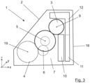
- Fig. 3
- eine alternative Ausgestaltung des erfindungsgemäßen Hybridgetriebes in einer Darstellung analog zu der in
Fig. 1 . - in der Darstellung der
Figur 1 ist ein in seiner Gesamtheit mit 1 bezeichnetes Hybridgetriebe für ein hier nicht dargestelltes Fahrzeug zu erkennen. Dabei sind in der Darstellung derFigur 1 drei Richtungen schematisch eingezeichnet. Eine Längsrichtung x und eine Hochrichtung z spannen dabei die inFigur 1 dargestellte Zeichnungsebene auf. Senkrecht dazu steht, in die Zeichnungsebene hineinragend, eine Querrichtung y. In der Darstellung derFigur 2 ist der Aufbau zusammen mit weiteren Komponenten dabei nochmals gedreht zu erkennen, sodass hier die Längsrichtung x aus der Blattebene heraus verläuft und die Darstellungsebene durch die Querrichtung y und die Hochrichtung z aufgespannt wird. - Das Hybridgetriebe 1 befindet sich nun teilweise in einem mit 2 bezeichneten Getriebegehäuse. Das Hybridgetriebe 1 umfasst eine elektrische Maschine 3 sowie ein Differentialgetriebe, von welchem hier ein Differentialeingangszahnrad 4 dargestellt ist. Dieses befindet sich im Eingriff mit einem Getriebe, welches eine Getriebeeingangswelle 5 sowie in dem hier dargestellten Ausführungsbeispiel zwei Vorgelegewellen 6 umfasst. Mit dickerer Linie eingezeichnet und in der in
Figur 2 dargestellten Querrichtung davor befindet sich eine mit 7 bezeichnete Kupplungseinrichtung. Diese Kupplungseinrichtung 7 ist für den inFigur 1 dargestellten Fall als Doppelkupplung ausgeführt, welche ergänzend eine Trennkupplung umfassen kann. Wie es später noch erläutert werden wird, wäre auch ein Aufbau mit einer Trennkupplung alleine denkbar. - Das hier nun dargestellte Doppelkupplungsgetriebe ist über die Kupplungseinrichtung 7, wie es in der Darstellung der
Figur 2 erkennbar wird, mit einem Verbrennungsmotor 8 verbunden. Verbunden im Sinne der Erfindung bedeutet dabei im Allgemeinen, dass die Verbindung mittelbar ausgebildet ist, über eine hier nicht dargestellte Einrichtung zur Tilgung und Dämpfung von Drehschwingungen, beispielsweise einem Zweimassenschwungrad oder dergleichen. Durch die Verbindung der Kupplungseinrichtung 7 mit dem Verbrennungsmotor 8 ist es so, dass einerseits über den Verbrennungsmotor 8 und andererseits über die elektrische Maschine 3 mit ihrer Rotordrehachse 9 ein Antrieb des Differentialgetriebes und damit des Fahrzeugs über das Differentialeingangszahnrad 4 erfolgen kann. Die elektrische Maschine 3 ist dabei in einer sogenannten Side-by-Side Anordnung zu einem Radsatz des Hybridgetriebes 1 angeordnet. - Mit der Side-by-Side-Anordnung der elektrischen Maschine 3 ist gemeint, dass die Rotordrehachse 9 achsparallel und versetzt zu der Getriebeeingangswelle 5 und auch jeweils achsparallel und versetzt zu den Vorgelegewellen 6 angeordnet ist. Die elektrische Maschine 3 kann beispielsweise über eine hier nicht eingezeichnete Stirnradpaarung oder auch über einen Kettentrieb mit einem Zahnrad bzw. einer Verzahnung des Hybridgetriebes 1 gekoppelt sein. Diese Verzahnung kann beispielsweise eine Außenverzahnung auf einem Lamellenträger der Kupplungseinrichtung sein oder auch ein Zahnrad im Radsatz des Getriebes, sodass die elektrische Maschine 4 ihre Kraft beispielsweise an die Getriebeeingangswelle oder insbesondere an eine der Vorgelegewellen 6 abgeben kann.
- In der Längsrichtung x, welche vorzugsweise auch die Fahrzeuglängsrichtung ist, sodass das Hybridgetriebe also quer zur Fahrzeuglängsrichtung bzw. Fahrtrichtung in dem Fahrzeug eingebaut ist, befindet sich benachbart zu der Getriebeeingangswelle 5 eine hydraulische Getriebesteuerung 10 sowie im Weiteren benachbart ein Getriebesteuergerät 11, welches die elektrische Steuerung des Radsatzes des Hybridgetriebes 1 übernimmt. Zur Steuerung der elektrischen Maschine 3 ist in der Hochrichtung z oberhalb und benachbart zu dem Getriebesteuergerät 11 eine Leistungselektronik 12 angeordnet. Diese umfasst zumindest eine mit 13 bezeichnete Platine eines Inverters, welche über einen dreiphasigen Wechselstromanschluss 14 mit der elektrischen Maschine 3 verbunden ist. Außerdem ist schematisch in der Leistungselektronik 12 ein Zwischenkreiskondensator 15 eingezeichnet. Über einen Gleichstromanschluss 16, welcher aus dem Getriebegehäuse 2 in einem mit 17 bezeichneten Bereich herausgeführt ist, wird die Leistungselektronik 12 und damit letztlich die elektrische Maschine 3 mit einer hier nicht dargestellten Traktionsbatterie des mit dem Hybridgetriebe 1 ausgestatteten Fahrzeugs verbunden.
- Das Getriebegehäuse 2 weist in der Längsrichtung x in der Darstellung der
Figur 1 rechts einen Gehäusedeckel 18 auf, welcher vorzugsweise in Fahrtrichtung vorne angeordnet ist. Dies macht den Aufbau hinsichtlich der Leistungselektronik 12 und des Getriebesteuergeräts 11 gut zugänglich, während der Gleichstromanschluss 16, welcher in dem mit 17 bezeichneten Bereich aus dem Getriebegehäuse 2 herausgeführt wird, entsprechend nach hinten verlagert ist, um im Falle eines Crashs eines mit dem Hybridgetriebe 1 ausgestatteten Fahrzeugs eine möglichst hohe Sicherheit zu bieten. - Da dieser Bereich 17 zur Realisierung des Gleichstromanschlusses am Gehäuse 2 in der Längsrichtung x zwischen der Rotorachse 9 der elektrischen Maschine 3 und einer Drehachse 19 des Differentialeingangszahnrads 4 liegt und damit in der Längsrichtung x sowohl von der Front des Getriebegehäuses 2 mit ihrem Deckel 18 als auch von der gegenüberliegenden Seite soweit entfernt, ist im Crashfall eine hohe Sicherheit gewährleistet ist.
- Die Leistungselektronik 12 umfasst dabei im Wesentlichen einen primären Teilabschnitt mit der Platine 13 des Inverters, welcher in der Längsrichtung x zwischen dem Deckel 18 und der elektrischen Maschine 3 angeordnet ist, sodass die Anordnung des Wechselstromanschlusses unterhalb der Rotordrehachse 9 der elektrischen Maschine 3 dafür sorgt, dass der Bauraum neben der elektrischen Maschine 3 ideal ausgenutzt wird. Ein weiterer Teil, z.B. mit dem Gleichstromanschluss 16 und dem Zwischenkreiskondensator 15, der Leistungselektronik 12 kann sich in der Längsrichtung x erstrecken und ist in Richtung der Hochrichtung z benachbart zur elektrischen Maschine angeordnet, sodass diese von der Leistungselektronik 12 also teilweise umschlossen wird. Überlappend zu der elektrischen Maschine 3 zwischen dem Getriebesteuergerät 11 und dem Radsatz mit seiner Eingangswelle 5 und den Vorgelegewellen 6 ist dabei die hydraulische Getriebesteuerung 10 angeordnet, sodass diese unmittelbar mit den entsprechenden Bauteilen innerhalb des Getriebes zusammenwirken kann, was den Aufbau ebenfalls kompakt und hinsichtlich der benötigten Leitungslängen sehr effizient macht.
- Eine Platine 20 des Getriebesteuergeräts 11 ist dabei in Hochrichtung Z benachbart und in Längsrichtung x parallel zu der Platine 13 des Inverters angeordnet. In Längsrichtung x sollten diese vorzugsweise weniger als 20 mm Abstand aufweisen. Idealerweise sind sie entlang der Hochrichtung z fluchtend hintereinander angeordnet.
- In der Darstellung der
Figur 2 mit Blick auf den Deckel 18 des Getriebegehäuses 2 ist nun zu erkennen, dass innerhalb des Getriebegehäuses das Differentialeingangszahnrad 4, die Vorgelegewellen 6, welche hier nicht dargestellt sind, und die Getriebeeingangswelle 5 angeordnet sind, ebenso wie die elektrische Maschine 3 und die hydraulische Getriebesteuerung 10 sowie die Kombination aus dem Getriebesteuergerät 11 unten und der Leistungselektronik 12 diese überlagernd oben. Eine Kurbelwelle des Verbrennungsmotors 8 treibt in diesem Szenario mittelbar in die Kupplungseinrichtung 7, welche hier als Doppelkupplung ausgebildet sein kann. Alles in allem lässt sich der Aufbau außerordentlich kompakt, vor allem in der Querrichtung Y, also entlang der Hauptachsen des Getriebes wie beispielsweise der Getriebeeingangswelle 5, realisieren. Der Aufbau kann dementsprechend quer zur Fahrtrichtung in das Fahrzeug eingebaut werden, sodass die schematische Darstellung derFigur 2 im Wesentlichen einer Blickrichtung auf die Front eines mit dem dort gezeigten Antriebsstrang 21 ausgestatten Fahrzeugs entspräche. - Dabei ist es so, dass in dem Getriebegehäuse 2 noch ausreichend Bauraum verbleibt, um die Außenkontur dieses Getriebegehäuses 2 an weitere in dem Fahrzeug benötigte Bauteile und Strukturen anzupassen. So ist in der Darstellung der
Figur 1 beispielsweise in dem in Hochrichtung z unteren Teil des Getriebegehäuses 2 eine optionale mit 22 bezeichnete Ausnehmung zu erkennen, in deren Bereich außerhalb des Getriebegehäuses 2 besonders bevorzugt Komponenten der Lenkung des Fahrzeugs angeordnet sein könnten. Die optionale Ausnehmung 22 ist vorteilhaft in Längsrichtung x gesehen zwischen der Drehachse 19 des Differentialeingangszahnrads 4 und dem Getriebesteuergerät 11 angeordnet. - In der Darstellung der
Figur 3 ist das Getriebegehäuse 2 nochmals dargestellt. Die optionale Ausnehmung 22 ist hier nicht vorhanden, der Deckel 18 des Getriebegehäuses 2 ist anders als in der Darstellung derFigur 1 nicht explizit dargestellt. Ansonsten soll der inFigur 1 dargestellte Aufbau weitgehend dem inFigur 3 dargestellten Aufbau entsprechen. Auch hier ist das Differentialeingangszahnrad 4 mit seiner Drehachse 19 erkennbar, ebenso wie die elektrische Maschine 3 mit ihrer Rotorachse 9. Eine hydraulische Getriebesteuerung 10 ist dargestellt und in Längsrichtung x benachbart dazu ist das Getriebesteuergerät 11 angeordnet, wobei auf die explizite Darstellung der Platine 20 verzichtet worden ist. Darüber befindet sich die Leistungselektronik 12, wobei auch hier auf, die Platine des Inverters, elektrische Anschlüsse und Details in der Darstellung verzichtet worden ist. - Der primäre Unterschied liegt nun darin, dass die Kupplungseinrichtung 7 hier als reine Trennkupplung ausgebildet ist. Anders als bei dem Aufbau in der Darstellung der
Figur 1 wird also kein Doppelkupplungsgetriebe mit zwei Vorgelegewellen 6 angesteuert, sondern ein einfaches Hybridgetriebe mit einem modifizierten Radsatz mit einer Eingangswelle 5 und einer einzigen Vorgelegewelle 6, über welche das Differentialeingangszahnrad 4 entsprechend angetrieben wird. Der Aufbau könnte beispielsweise in Form eines simplen automatisierten Schaltgetriebes realisiert sein, welches mit der elektrischen Maschine 3 entsprechend hybridisiert ist. Diese ist in der oben schon beschriebenen Side-by-Side Anordnung zu dem modifizierten Radsatz in dem Hybridgetriebe 1 angeordnet. Der entscheidende Aufbau der integrierten Steuerung mit der Leistungselektronik 12 und dem Getriebesteuergerät 11 ist identisch zu dem zuvor beschriebenen Ausführungsbeispiel.
Claims (12)
- Hybridgetriebe (1) für ein Fahrzeug, mit- einer in eine Querrichtung (y) verlaufende Getriebeeingangswelle (5),- zumindest einer parallel zu der Getriebeeingangswelle (5) angeordneten Vorgelegewelle (6),- einer koaxial zu der Getriebeeingangswelle (5) angeordneten Kupplungseinrichtung (7), welche wenigstens eine Kupplung aufweist,- einem Differentialgetriebe, welches ein Differentialeingangszahnrad (4) aufweist,
wobei eine Drehachse (19) des Differentialeingangszahnrads parallel zu der Getriebeeingangswelle (5) angeordnet ist,- einer elektrischen Maschine (3), welche einen Rotor und einen Stator aufweist, wobei eine Rotordrehachse (9) parallel zu der Getriebeeingangswelle (5) angeordnet ist,- einem Getriebesteuergerät (11), wobei- in einer Längsrichtung (x) gesehen, welche senkrecht zu der Querrichtung (y)
angeordnet ist, das Differentialeingangszahnrad (4), die Getriebeeingangswelle (5) und eine das Getriebesteuergerät (11) umfassende Getriebesteuerung in der genannten Reihenfolge nacheinander angeordnet sind,wobei in einer Hochrichtung (z), welche senkrecht zu der Querrichtung (y) und senkrecht zu der Längsrichtung (x) angeordnet ist, zumindest ein Teil einer Leistungselektronik (12) für die elektrische Maschine (3) benachbart zu dem Getriebesteuergerät (11) angeordnet ist,wobei die elektrische Maschine (3) in der Hochrichtung (z) benachbart und oberhalb einer hydraulischen Getriebesteuerung (10) und in Längsrichtung (x) überlappend zu dieser angeordnet ist,dadurch gekennzeichnet, dassein Gleichstromanschluss (16) für die Leistungselektronik (12) in der Hochrichtung (z) oberhalb der Rotordrehachse (9) und in Längsrichtung (x) zwischen der Drehachse (19) des Differentialeingangszahnrads (4) und der Rotordrehachse (9) angeordnet ist. - Hybridgetriebe (1) nach Anspruch 1,
dadurch gekennzeichnet, dass
der benachbart zu dem Getriebesteuergerät (11) angeordnete zumindest eine Teil der Leistungselektronik (12) im bestimmungsgemäßen Einsatz oberhalb des Getriebesteuergeräts (11) angeordnet ist. - Hybridgetriebe (1) nach Anspruch 1 oder 2,
dadurch gekennzeichnet, dass
ein weiterer Teil der Leistungselektronik (12) sich in der Längsrichtung (x) erstreckt und in der Hochrichtung (z) oberhalb der elektrischen Maschine (3) angeordnet ist. - Hybridgetriebe (1) nach Anspruch 1, 2 oder 3,
dadurch gekennzeichnet, dass
die Leistungselektronik (12) in der Längsrichtung (x) und/oder in der Querrichtung (y) zumindest teilweise überlappend zu dem Getriebesteuergerät (11) angeordnet ist. - Hybridgetriebe (1) nach einem der Ansprüche 1 bis 4,
dadurch gekennzeichnet, dass
eine Platine (13) eines Inverters der Leistungselektronik (12) in der Hochrichtung (z) benachbart und in der Längsrichtung (x) parallel zu einer Platine (20) des Getriebesteuergeräts (11) angeordnet ist. - Hybridgetriebe (1) nach Anspruch 5,
dadurch gekennzeichnet, dass
die Platine (13) des Inverters der Leistungselektronik (12) weniger als 20 mm beabstandet, in der Hochrichtung (z) fluchtend, zu der Platine (20) des Getriebesteuergeräts (11) angeordnet ist. - Hybridgetriebe (1) nach einem der Ansprüche 1 bis 6,
dadurch gekennzeichnet, dass
eine Rotordrehachse (9) der elektrischen Maschine in Längsrichtung (x) zwischen der Getriebeeingangswelle (5) und zumindest einem Teil der Leistungselektronik (12) angeordnet ist. - Hybridgetriebe (1) nach einem der Ansprüche 1 bis 7,
dadurch gekennzeichnet, dass
die elektrische Maschine (3) in der Längsrichtung (x) benachbart zu zumindest einem Teil der Leistungselektronik (12) angeordnet ist. - Hybridgetriebe (1) nach Anspruch 7,
dadurch gekennzeichnet, dass
ein Wechselstromanschluss (14), welcher die elektrische Maschine (3) und die Leistungselektronik (12) verbindet, in der Hochrichtung (z) unterhalb der Rotordrehachse (9) angeordnet ist. - Hybridgetriebe (1) nach einem der Ansprüche 1 bis 9,
dadurch gekennzeichnet, dass
ein Getriebegehäuse (2), welches zumindest das Differentialeingangszahnrad (4), die Getriebeeingangswelle (5), die mindestens eine Vorgelegewelle (6), die elektrische Maschine (3), das Getriebesteuergerät (11), die hydraulische Getriebesteuerung (10) und die Leistungselektronik (12) aufnimmt, einen Gehäusedeckel (18) umfasst, welcher in der Längsrichtung (x) auf der der Getriebeeingangswelle (5) abgewandten Seite des Getriebesteuergeräts (11) und zumindest eines Teils der Leistungselektronik (12) angeordnet ist. - Hybridgetriebe (1) nach einem der Ansprüche 1 bis 10,
dadurch gekennzeichnet, dass
die Querrichtung (y), die Längsrichtung (x) und die Hochrichtung (z) bei einem in ein Fahrzeug eingebautem Hybridgetriebe (1) in der genannten Reihenfolge der Fahrzeugquerrichtung, der Fahrzeuglängsrichtung und der Fahrzeughochrichtung entsprechen. - Hybridgetriebe (1) nach einem der Ansprüche 1 bis 11,
dadurch gekennzeichnet, dass
die Kupplungseinrichtung (7) eine Doppelkupplung und/oder eine Trennkupplung aufweist.
Applications Claiming Priority (3)
| Application Number | Priority Date | Filing Date | Title |
|---|---|---|---|
| DE102020007296.8A DE102020007296B4 (de) | 2020-11-30 | 2020-11-30 | Hybridgetriebe für ein Fahrzeug |
| EP21798315.4A EP4251450B1 (de) | 2020-11-30 | 2021-10-18 | Hybridgetriebe für ein fahrzeug |
| PCT/EP2021/078837 WO2022111911A1 (de) | 2020-11-30 | 2021-10-18 | Hybridgetriebe für ein fahrzeug |
Related Parent Applications (2)
| Application Number | Title | Priority Date | Filing Date |
|---|---|---|---|
| EP21798315.4A Division-Into EP4251450B1 (de) | 2020-11-30 | 2021-10-18 | Hybridgetriebe für ein fahrzeug |
| EP21798315.4A Division EP4251450B1 (de) | 2020-11-30 | 2021-10-18 | Hybridgetriebe für ein fahrzeug |
Publications (3)
| Publication Number | Publication Date |
|---|---|
| EP4286193A1 EP4286193A1 (de) | 2023-12-06 |
| EP4286193B1 true EP4286193B1 (de) | 2024-06-26 |
| EP4286193C0 EP4286193C0 (de) | 2024-06-26 |
Family
ID=78372008
Family Applications (3)
| Application Number | Title | Priority Date | Filing Date |
|---|---|---|---|
| EP23182829.4A Active EP4286193B1 (de) | 2020-11-30 | 2021-10-18 | Hybridgetriebe für ein fahrzeug |
| EP23182825.2A Active EP4286192B1 (de) | 2020-11-30 | 2021-10-18 | Hybridgetriebe für ein fahrzeug |
| EP21798315.4A Active EP4251450B1 (de) | 2020-11-30 | 2021-10-18 | Hybridgetriebe für ein fahrzeug |
Family Applications After (2)
| Application Number | Title | Priority Date | Filing Date |
|---|---|---|---|
| EP23182825.2A Active EP4286192B1 (de) | 2020-11-30 | 2021-10-18 | Hybridgetriebe für ein fahrzeug |
| EP21798315.4A Active EP4251450B1 (de) | 2020-11-30 | 2021-10-18 | Hybridgetriebe für ein fahrzeug |
Country Status (6)
| Country | Link |
|---|---|
| US (1) | US11938824B2 (de) |
| EP (3) | EP4286193B1 (de) |
| JP (3) | JP7497530B2 (de) |
| CN (3) | CN116529111A (de) |
| DE (1) | DE102020007296B4 (de) |
| WO (1) | WO2022111911A1 (de) |
Families Citing this family (1)
| Publication number | Priority date | Publication date | Assignee | Title |
|---|---|---|---|---|
| DE102022003652A1 (de) | 2022-10-04 | 2024-04-04 | Mercedes-Benz Group AG | Elektrische Komponente für ein Kraftfahrzeug mit einem Gehäuse und einer Stützstruktur |
Family Cites Families (44)
| Publication number | Priority date | Publication date | Assignee | Title |
|---|---|---|---|---|
| JP3168895B2 (ja) | 1995-12-06 | 2001-05-21 | トヨタ自動車株式会社 | ハイブリッド駆動装置 |
| JP3891533B2 (ja) * | 1998-11-16 | 2007-03-14 | アイシン・エィ・ダブリュ株式会社 | 駆動装置 |
| JP3882994B2 (ja) | 2001-12-27 | 2007-02-21 | アイシン・エィ・ダブリュ株式会社 | 電動機制御ユニット冷却装置 |
| KR100634589B1 (ko) * | 2003-12-24 | 2006-10-13 | 현대자동차주식회사 | 하이브리드 전기자동차용 이중 클러치 변속기 및 그모드별 작동방법 |
| JP4835192B2 (ja) * | 2006-02-20 | 2011-12-14 | アイシン精機株式会社 | 車両用駆動装置 |
| DE102007001840A1 (de) * | 2007-01-12 | 2008-07-17 | Voith Patent Gmbh | Hybridantrieb, insbesondere für ein Kraftfahrzeug |
| JP5051456B2 (ja) | 2008-02-20 | 2012-10-17 | アイシン・エィ・ダブリュ株式会社 | ハイブリッド駆動装置 |
| JP5035631B2 (ja) | 2008-04-28 | 2012-09-26 | アイシン・エィ・ダブリュ株式会社 | 駆動装置 |
| JP5200999B2 (ja) * | 2009-02-27 | 2013-06-05 | 日産自動車株式会社 | 変速機の油圧回路構造 |
| WO2010119320A1 (en) * | 2009-04-15 | 2010-10-21 | Nissan Motor Co., Ltd. | Vehicle component mounting arrangement |
| JP5375378B2 (ja) | 2009-07-06 | 2013-12-25 | マツダ株式会社 | ハイブリッド車両用駆動装置 |
| JP2011109839A (ja) * | 2009-11-19 | 2011-06-02 | Aisin Seiki Co Ltd | 回転電機 |
| DE102010002746A1 (de) | 2010-03-11 | 2011-09-15 | Zf Friedrichshafen Ag | Hybridgetriebe |
| JP5168598B2 (ja) | 2010-03-31 | 2013-03-21 | アイシン・エィ・ダブリュ株式会社 | ハイブリッド駆動装置 |
| JP5152604B2 (ja) * | 2010-11-05 | 2013-02-27 | 本田技研工業株式会社 | 車両の駆動装置 |
| US8905885B2 (en) | 2011-02-04 | 2014-12-09 | Aisin Aw Co., Ltd. | Vehicle drive device |
| JP2013034439A (ja) * | 2011-08-09 | 2013-02-21 | Mitsubishi Agricultural Machinery Co Ltd | 乗用田植機 |
| US9242544B2 (en) * | 2011-09-23 | 2016-01-26 | Kanzaki Kokyukoki Mfg. Co., Ltd. | Vehicle with electric transaxle |
| JP2013147046A (ja) * | 2012-01-17 | 2013-08-01 | Nissan Motor Co Ltd | ハイブリッド車両のパワートレーン系要素配置構造 |
| JP5929676B2 (ja) * | 2012-09-28 | 2016-06-08 | アイシン・エィ・ダブリュ株式会社 | 車両用駆動装置 |
| DE102012019971B4 (de) | 2012-10-08 | 2017-07-20 | Getrag Getriebe- Und Zahnradfabrik Hermann Hagenmeyer Gmbh & Cie Kg | Hybrid-Antriebsstrang für ein Kraftfahrzeug |
| JP6070444B2 (ja) * | 2013-06-28 | 2017-02-01 | アイシン・エィ・ダブリュ株式会社 | 車両用駆動装置 |
| DE112014001112T5 (de) | 2013-05-31 | 2015-12-24 | Aisin Aw Co., Ltd. | Fahrzeugantriebsvorrichtung |
| US9358865B1 (en) | 2013-07-31 | 2016-06-07 | Raymond C. Sherry | Flywheel-powered vehicle |
| JP2015067221A (ja) * | 2013-09-30 | 2015-04-13 | アイシン・エィ・ダブリュ株式会社 | 車両用駆動装置 |
| CN105684285A (zh) | 2013-11-07 | 2016-06-15 | 日立汽车系统株式会社 | 电力转换装置 |
| WO2015163459A1 (ja) | 2014-04-25 | 2015-10-29 | アイシン・エィ・ダブリュ株式会社 | 車両用駆動装置 |
| JP6245075B2 (ja) | 2014-05-28 | 2017-12-13 | アイシン・エィ・ダブリュ株式会社 | 車両用駆動装置 |
| US10675962B2 (en) * | 2015-01-28 | 2020-06-09 | Honda Motor Co., Ltd. | Hybrid vehicle driving system |
| CN105216598B (zh) * | 2015-09-28 | 2018-10-16 | 上海蔚来汽车有限公司 | 一种汽车用的电驱动系统及使用了该电驱动系统的汽车 |
| DE102015014096A1 (de) | 2015-10-30 | 2016-05-25 | Daimler Ag | Antriebseinrichtung für ein Hybrid-Fahrzeug |
| CN105383283A (zh) | 2015-11-26 | 2016-03-09 | 上海汽车变速器有限公司 | 基于双离合器变速器的混合动力驱动系统 |
| DE102016215184B4 (de) * | 2016-08-16 | 2024-03-21 | Zf Friedrichshafen Ag | Hybridantrieb |
| JP6715759B2 (ja) | 2016-12-28 | 2020-07-01 | 日立オートモティブシステムズ株式会社 | インバータ駆動装置およびそれを用いた電動車両システム |
| US10035414B1 (en) * | 2017-01-18 | 2018-07-31 | GM Global Technology Operations LLC | Automatically-shiftable hybrid transaxle |
| JP6565946B2 (ja) | 2017-01-27 | 2019-08-28 | トヨタ自動車株式会社 | 制御部品ユニットの取付構造 |
| DE102017201894A1 (de) * | 2017-02-07 | 2018-08-09 | Zf Friedrichshafen Ag | Aufbau eines Getriebes für ein Hybridfahrzeug |
| JP6249115B1 (ja) | 2017-02-09 | 2017-12-20 | トヨタ自動車株式会社 | 車両 |
| JP2019048608A (ja) * | 2017-09-12 | 2019-03-28 | トヨタ自動車株式会社 | 電気機器の車載構造 |
| US11427080B2 (en) * | 2017-10-24 | 2022-08-30 | Nissan Motor Co., Ltd. | Power transmission device for four-wheel drive vehicle |
| DE102018002167B3 (de) | 2018-03-16 | 2019-07-11 | Daimler Ag | Doppelkupplungsgetriebe |
| JP7155925B2 (ja) * | 2018-11-16 | 2022-10-19 | トヨタ自動車株式会社 | 車両用駆動装置 |
| JP2023532586A (ja) * | 2020-07-08 | 2023-07-28 | ノボ・ノルデイスク・エー/エス | アルゴリズム自動較正を有する用量設定センサ組立品 |
| US11912132B2 (en) | 2020-11-30 | 2024-02-27 | Mercedes-Benz Group AG | Hybrid transmission for a vehicle |
-
2020
- 2020-11-30 DE DE102020007296.8A patent/DE102020007296B4/de active Active
-
2021
- 2021-10-18 EP EP23182829.4A patent/EP4286193B1/de active Active
- 2021-10-18 WO PCT/EP2021/078837 patent/WO2022111911A1/de not_active Ceased
- 2021-10-18 JP JP2023532586A patent/JP7497530B2/ja active Active
- 2021-10-18 EP EP23182825.2A patent/EP4286192B1/de active Active
- 2021-10-18 CN CN202180080066.4A patent/CN116529111A/zh active Pending
- 2021-10-18 CN CN202311064751.5A patent/CN116872713A/zh active Pending
- 2021-10-18 US US18/039,009 patent/US11938824B2/en active Active
- 2021-10-18 CN CN202311064709.3A patent/CN116852971A/zh active Pending
- 2021-10-18 EP EP21798315.4A patent/EP4251450B1/de active Active
-
2023
- 2023-07-28 JP JP2023123238A patent/JP7546119B2/ja active Active
- 2023-07-28 JP JP2023123240A patent/JP7520192B2/ja active Active
Also Published As
| Publication number | Publication date |
|---|---|
| WO2022111911A1 (de) | 2022-06-02 |
| CN116529111A (zh) | 2023-08-01 |
| EP4251450B1 (de) | 2024-01-31 |
| EP4251450C0 (de) | 2024-01-31 |
| JP2023178514A (ja) | 2023-12-15 |
| EP4286192A1 (de) | 2023-12-06 |
| CN116852971A (zh) | 2023-10-10 |
| JP7497530B2 (ja) | 2024-06-10 |
| EP4286192B1 (de) | 2024-07-03 |
| JP7546119B2 (ja) | 2024-09-05 |
| EP4251450A1 (de) | 2023-10-04 |
| EP4286192C0 (de) | 2024-07-03 |
| JP2023551043A (ja) | 2023-12-06 |
| JP7520192B2 (ja) | 2024-07-22 |
| DE102020007296B4 (de) | 2025-03-27 |
| JP2023175676A (ja) | 2023-12-12 |
| EP4286193C0 (de) | 2024-06-26 |
| US20240001752A1 (en) | 2024-01-04 |
| CN116872713A (zh) | 2023-10-13 |
| US11938824B2 (en) | 2024-03-26 |
| EP4286193A1 (de) | 2023-12-06 |
| DE102020007296A1 (de) | 2022-06-02 |
Similar Documents
| Publication | Publication Date | Title |
|---|---|---|
| EP4208360B1 (de) | Rein elektrisches antriebssystem mit zwei motoren | |
| EP2176085B1 (de) | Antriebsstrang für ein kraftfahrzeug | |
| DE102017220165B4 (de) | Antriebsvorrichtung für eine Fahrzeugachse eines zweispurigen Fahrzeugs | |
| EP3360742A1 (de) | Hybridantriebsstrang für ein kraftfahrzeug | |
| WO2011151322A1 (de) | Getriebeanordnung | |
| DE102019107538A1 (de) | Torque-Vectoring-Getriebe für ein Kraftfahrzeug | |
| EP1936234A2 (de) | Doppelkupplungsgetriebe | |
| WO2018073378A1 (de) | Antriebsbaugruppe mit e-maschine für ein kraftfahrzeug | |
| EP3500777B1 (de) | Getriebe für ein kraftfahrzeug | |
| DE102005003077B4 (de) | Antriebseinheit für ein Kraftfahrzeug | |
| DE102017222443B4 (de) | Automatikgetriebe | |
| EP4286192B1 (de) | Hybridgetriebe für ein fahrzeug | |
| DE102018204474A1 (de) | Getriebe für einen Schiffsantrieb und Schiffsantrieb | |
| DE10143289A1 (de) | Automatisiertes Schaltgetriebe | |
| DE102019214572A1 (de) | Schiffsgetriebe und Schiffsantrieb | |
| DE102012007623B4 (de) | Motor-Getriebe-Einheit | |
| DE102020004582A1 (de) | Hybridantriebssystem für ein Fahrzeug | |
| EP4046845B1 (de) | Antriebsstrang für ein kraftfahrzeug | |
| DE102012208678A1 (de) | Antriebsanordnung | |
| EP3170689A1 (de) | Hybridfahrzeug | |
| EP3492294B1 (de) | Umlenkgetriebeanordnung | |
| DE102017216231B4 (de) | Antriebseinheit für ein Kraftfahrzeug, Kraftfahrzeug sowie Verfahren zum Betrieb einer Antriebseinheit | |
| EP2179881A1 (de) | Kraftfahrzeug mit Allradantrieb | |
| EP3374221B1 (de) | Antriebseinrichtung für ein kraftfahrzeug | |
| DE102019112855A1 (de) | Antriebsvorrichtung mit einem unterhalb einer Leistungselektronikeinheit angeordneten Wärmetauscher |
Legal Events
| Date | Code | Title | Description |
|---|---|---|---|
| PUAI | Public reference made under article 153(3) epc to a published international application that has entered the european phase |
Free format text: ORIGINAL CODE: 0009012 |
|
| STAA | Information on the status of an ep patent application or granted ep patent |
Free format text: STATUS: THE APPLICATION HAS BEEN PUBLISHED |
|
| AC | Divisional application: reference to earlier application |
Ref document number: 4251450 Country of ref document: EP Kind code of ref document: P |
|
| AK | Designated contracting states |
Kind code of ref document: A1 Designated state(s): AL AT BE BG CH CY CZ DE DK EE ES FI FR GB GR HR HU IE IS IT LI LT LU LV MC MK MT NL NO PL PT RO RS SE SI SK SM TR |
|
| STAA | Information on the status of an ep patent application or granted ep patent |
Free format text: STATUS: REQUEST FOR EXAMINATION WAS MADE |
|
| 17P | Request for examination filed |
Effective date: 20231219 |
|
| RBV | Designated contracting states (corrected) |
Designated state(s): AL AT BE BG CH CY CZ DE DK EE ES FI FR GB GR HR HU IE IS IT LI LT LU LV MC MK MT NL NO PL PT RO RS SE SI SK SM TR |
|
| GRAP | Despatch of communication of intention to grant a patent |
Free format text: ORIGINAL CODE: EPIDOSNIGR1 |
|
| STAA | Information on the status of an ep patent application or granted ep patent |
Free format text: STATUS: GRANT OF PATENT IS INTENDED |
|
| RIC1 | Information provided on ipc code assigned before grant |
Ipc: B60K 6/387 20071001ALI20240326BHEP Ipc: B60K 6/36 20071001ALI20240326BHEP Ipc: B60K 6/48 20071001ALI20240326BHEP Ipc: B60K 6/40 20071001AFI20240326BHEP |
|
| GRAS | Grant fee paid |
Free format text: ORIGINAL CODE: EPIDOSNIGR3 |
|
| INTG | Intention to grant announced |
Effective date: 20240422 |
|
| GRAA | (expected) grant |
Free format text: ORIGINAL CODE: 0009210 |
|
| STAA | Information on the status of an ep patent application or granted ep patent |
Free format text: STATUS: THE PATENT HAS BEEN GRANTED |
|
| AC | Divisional application: reference to earlier application |
Ref document number: 4251450 Country of ref document: EP Kind code of ref document: P |
|
| AK | Designated contracting states |
Kind code of ref document: B1 Designated state(s): AL AT BE BG CH CY CZ DE DK EE ES FI FR GB GR HR HU IE IS IT LI LT LU LV MC MK MT NL NO PL PT RO RS SE SI SK SM TR |
|
| REG | Reference to a national code |
Ref country code: GB Ref legal event code: FG4D Free format text: NOT ENGLISH |
|
| REG | Reference to a national code |
Ref country code: CH Ref legal event code: EP |
|
| REG | Reference to a national code |
Ref country code: DE Ref legal event code: R096 Ref document number: 502021004166 Country of ref document: DE |
|
| U01 | Request for unitary effect filed |
Effective date: 20240708 |
|
| U07 | Unitary effect registered |
Designated state(s): AT BE BG DE DK EE FI FR IT LT LU LV MT NL PT RO SE SI Effective date: 20240902 |
|
| PG25 | Lapsed in a contracting state [announced via postgrant information from national office to epo] |
Ref country code: HR Free format text: LAPSE BECAUSE OF FAILURE TO SUBMIT A TRANSLATION OF THE DESCRIPTION OR TO PAY THE FEE WITHIN THE PRESCRIBED TIME-LIMIT Effective date: 20240626 |
|
| PG25 | Lapsed in a contracting state [announced via postgrant information from national office to epo] |
Ref country code: GR Free format text: LAPSE BECAUSE OF FAILURE TO SUBMIT A TRANSLATION OF THE DESCRIPTION OR TO PAY THE FEE WITHIN THE PRESCRIBED TIME-LIMIT Effective date: 20240927 |
|
| PG25 | Lapsed in a contracting state [announced via postgrant information from national office to epo] |
Ref country code: NO Free format text: LAPSE BECAUSE OF FAILURE TO SUBMIT A TRANSLATION OF THE DESCRIPTION OR TO PAY THE FEE WITHIN THE PRESCRIBED TIME-LIMIT Effective date: 20240926 Ref country code: HR Free format text: LAPSE BECAUSE OF FAILURE TO SUBMIT A TRANSLATION OF THE DESCRIPTION OR TO PAY THE FEE WITHIN THE PRESCRIBED TIME-LIMIT Effective date: 20240626 Ref country code: GR Free format text: LAPSE BECAUSE OF FAILURE TO SUBMIT A TRANSLATION OF THE DESCRIPTION OR TO PAY THE FEE WITHIN THE PRESCRIBED TIME-LIMIT Effective date: 20240927 Ref country code: RS Free format text: LAPSE BECAUSE OF FAILURE TO SUBMIT A TRANSLATION OF THE DESCRIPTION OR TO PAY THE FEE WITHIN THE PRESCRIBED TIME-LIMIT Effective date: 20240926 |
|
| U20 | Renewal fee for the european patent with unitary effect paid |
Year of fee payment: 4 Effective date: 20241025 |
|
| PG25 | Lapsed in a contracting state [announced via postgrant information from national office to epo] |
Ref country code: PL Free format text: LAPSE BECAUSE OF FAILURE TO SUBMIT A TRANSLATION OF THE DESCRIPTION OR TO PAY THE FEE WITHIN THE PRESCRIBED TIME-LIMIT Effective date: 20240626 |
|
| PG25 | Lapsed in a contracting state [announced via postgrant information from national office to epo] |
Ref country code: IS Free format text: LAPSE BECAUSE OF FAILURE TO SUBMIT A TRANSLATION OF THE DESCRIPTION OR TO PAY THE FEE WITHIN THE PRESCRIBED TIME-LIMIT Effective date: 20241026 |
|
| PG25 | Lapsed in a contracting state [announced via postgrant information from national office to epo] |
Ref country code: CZ Free format text: LAPSE BECAUSE OF FAILURE TO SUBMIT A TRANSLATION OF THE DESCRIPTION OR TO PAY THE FEE WITHIN THE PRESCRIBED TIME-LIMIT Effective date: 20240626 |
|
| PG25 | Lapsed in a contracting state [announced via postgrant information from national office to epo] |
Ref country code: SK Free format text: LAPSE BECAUSE OF FAILURE TO SUBMIT A TRANSLATION OF THE DESCRIPTION OR TO PAY THE FEE WITHIN THE PRESCRIBED TIME-LIMIT Effective date: 20240626 |
|
| PG25 | Lapsed in a contracting state [announced via postgrant information from national office to epo] |
Ref country code: SM Free format text: LAPSE BECAUSE OF FAILURE TO SUBMIT A TRANSLATION OF THE DESCRIPTION OR TO PAY THE FEE WITHIN THE PRESCRIBED TIME-LIMIT Effective date: 20240626 Ref country code: ES Free format text: LAPSE BECAUSE OF FAILURE TO SUBMIT A TRANSLATION OF THE DESCRIPTION OR TO PAY THE FEE WITHIN THE PRESCRIBED TIME-LIMIT Effective date: 20240626 |
|
| PG25 | Lapsed in a contracting state [announced via postgrant information from national office to epo] |
Ref country code: SM Free format text: LAPSE BECAUSE OF FAILURE TO SUBMIT A TRANSLATION OF THE DESCRIPTION OR TO PAY THE FEE WITHIN THE PRESCRIBED TIME-LIMIT Effective date: 20240626 Ref country code: SK Free format text: LAPSE BECAUSE OF FAILURE TO SUBMIT A TRANSLATION OF THE DESCRIPTION OR TO PAY THE FEE WITHIN THE PRESCRIBED TIME-LIMIT Effective date: 20240626 Ref country code: PL Free format text: LAPSE BECAUSE OF FAILURE TO SUBMIT A TRANSLATION OF THE DESCRIPTION OR TO PAY THE FEE WITHIN THE PRESCRIBED TIME-LIMIT Effective date: 20240626 Ref country code: IS Free format text: LAPSE BECAUSE OF FAILURE TO SUBMIT A TRANSLATION OF THE DESCRIPTION OR TO PAY THE FEE WITHIN THE PRESCRIBED TIME-LIMIT Effective date: 20241026 Ref country code: ES Free format text: LAPSE BECAUSE OF FAILURE TO SUBMIT A TRANSLATION OF THE DESCRIPTION OR TO PAY THE FEE WITHIN THE PRESCRIBED TIME-LIMIT Effective date: 20240626 Ref country code: CZ Free format text: LAPSE BECAUSE OF FAILURE TO SUBMIT A TRANSLATION OF THE DESCRIPTION OR TO PAY THE FEE WITHIN THE PRESCRIBED TIME-LIMIT Effective date: 20240626 |
|
| PLBE | No opposition filed within time limit |
Free format text: ORIGINAL CODE: 0009261 |
|
| STAA | Information on the status of an ep patent application or granted ep patent |
Free format text: STATUS: NO OPPOSITION FILED WITHIN TIME LIMIT |
|
| REG | Reference to a national code |
Ref country code: CH Ref legal event code: PL |
|
| 26N | No opposition filed |
Effective date: 20250327 |
|
| PG25 | Lapsed in a contracting state [announced via postgrant information from national office to epo] |
Ref country code: MC Free format text: LAPSE BECAUSE OF FAILURE TO SUBMIT A TRANSLATION OF THE DESCRIPTION OR TO PAY THE FEE WITHIN THE PRESCRIBED TIME-LIMIT Effective date: 20240626 |
|
| PG25 | Lapsed in a contracting state [announced via postgrant information from national office to epo] |
Ref country code: CH Free format text: LAPSE BECAUSE OF NON-PAYMENT OF DUE FEES Effective date: 20241031 |
|
| PG25 | Lapsed in a contracting state [announced via postgrant information from national office to epo] |
Ref country code: IE Free format text: LAPSE BECAUSE OF NON-PAYMENT OF DUE FEES Effective date: 20241018 |
|
| U20 | Renewal fee for the european patent with unitary effect paid |
Year of fee payment: 5 Effective date: 20251027 |
|
| PG25 | Lapsed in a contracting state [announced via postgrant information from national office to epo] |
Ref country code: CY Free format text: LAPSE BECAUSE OF FAILURE TO SUBMIT A TRANSLATION OF THE DESCRIPTION OR TO PAY THE FEE WITHIN THE PRESCRIBED TIME-LIMIT; INVALID AB INITIO Effective date: 20211018 |
|
| PG25 | Lapsed in a contracting state [announced via postgrant information from national office to epo] |
Ref country code: HU Free format text: LAPSE BECAUSE OF FAILURE TO SUBMIT A TRANSLATION OF THE DESCRIPTION OR TO PAY THE FEE WITHIN THE PRESCRIBED TIME-LIMIT; INVALID AB INITIO Effective date: 20211018 |