EP4283984A1 - Videomonitorvorrichtung, videomonitorsystem, videomonitorverfahren und videomonitorprogramm - Google Patents
Videomonitorvorrichtung, videomonitorsystem, videomonitorverfahren und videomonitorprogramm Download PDFInfo
- Publication number
- EP4283984A1 EP4283984A1 EP21926619.4A EP21926619A EP4283984A1 EP 4283984 A1 EP4283984 A1 EP 4283984A1 EP 21926619 A EP21926619 A EP 21926619A EP 4283984 A1 EP4283984 A1 EP 4283984A1
- Authority
- EP
- European Patent Office
- Prior art keywords
- level
- mobile object
- viewability
- movable cameras
- video
- Prior art date
- Legal status (The legal status is an assumption and is not a legal conclusion. Google has not performed a legal analysis and makes no representation as to the accuracy of the status listed.)
- Pending
Links
Images








Classifications
-
- G—PHYSICS
- G06—COMPUTING OR CALCULATING; COUNTING
- G06V—IMAGE OR VIDEO RECOGNITION OR UNDERSTANDING
- G06V20/00—Scenes; Scene-specific elements
- G06V20/50—Context or environment of the image
- G06V20/52—Surveillance or monitoring of activities, e.g. for recognising suspicious objects
-
- H—ELECTRICITY
- H04—ELECTRIC COMMUNICATION TECHNIQUE
- H04N—PICTORIAL COMMUNICATION, e.g. TELEVISION
- H04N23/00—Cameras or camera modules comprising electronic image sensors; Control thereof
- H04N23/90—Arrangement of cameras or camera modules, e.g. multiple cameras in TV studios or sports stadiums
-
- G—PHYSICS
- G06—COMPUTING OR CALCULATING; COUNTING
- G06T—IMAGE DATA PROCESSING OR GENERATION, IN GENERAL
- G06T7/00—Image analysis
- G06T7/20—Analysis of motion
- G06T7/292—Multi-camera tracking
-
- G—PHYSICS
- G06—COMPUTING OR CALCULATING; COUNTING
- G06T—IMAGE DATA PROCESSING OR GENERATION, IN GENERAL
- G06T7/00—Image analysis
- G06T7/70—Determining position or orientation of objects or cameras
-
- G—PHYSICS
- G06—COMPUTING OR CALCULATING; COUNTING
- G06V—IMAGE OR VIDEO RECOGNITION OR UNDERSTANDING
- G06V10/00—Arrangements for image or video recognition or understanding
- G06V10/20—Image preprocessing
- G06V10/26—Segmentation of patterns in the image field; Cutting or merging of image elements to establish the pattern region, e.g. clustering-based techniques; Detection of occlusion
-
- G—PHYSICS
- G06—COMPUTING OR CALCULATING; COUNTING
- G06V—IMAGE OR VIDEO RECOGNITION OR UNDERSTANDING
- G06V10/00—Arrangements for image or video recognition or understanding
- G06V10/70—Arrangements for image or video recognition or understanding using pattern recognition or machine learning
- G06V10/74—Image or video pattern matching; Proximity measures in feature spaces
- G06V10/761—Proximity, similarity or dissimilarity measures
-
- H—ELECTRICITY
- H04—ELECTRIC COMMUNICATION TECHNIQUE
- H04N—PICTORIAL COMMUNICATION, e.g. TELEVISION
- H04N23/00—Cameras or camera modules comprising electronic image sensors; Control thereof
- H04N23/60—Control of cameras or camera modules
- H04N23/695—Control of camera direction for changing a field of view, e.g. pan, tilt or based on tracking of objects
-
- H—ELECTRICITY
- H04—ELECTRIC COMMUNICATION TECHNIQUE
- H04N—PICTORIAL COMMUNICATION, e.g. TELEVISION
- H04N7/00—Television systems
- H04N7/18—Closed-circuit television [CCTV] systems, i.e. systems in which the video signal is not broadcast
- H04N7/181—Closed-circuit television [CCTV] systems, i.e. systems in which the video signal is not broadcast for receiving images from a plurality of remote sources
-
- G—PHYSICS
- G06—COMPUTING OR CALCULATING; COUNTING
- G06T—IMAGE DATA PROCESSING OR GENERATION, IN GENERAL
- G06T2207/00—Indexing scheme for image analysis or image enhancement
- G06T2207/10—Image acquisition modality
- G06T2207/10024—Color image
-
- G—PHYSICS
- G06—COMPUTING OR CALCULATING; COUNTING
- G06T—IMAGE DATA PROCESSING OR GENERATION, IN GENERAL
- G06T2207/00—Indexing scheme for image analysis or image enhancement
- G06T2207/10—Image acquisition modality
- G06T2207/10028—Range image; Depth image; 3D point clouds
-
- G—PHYSICS
- G06—COMPUTING OR CALCULATING; COUNTING
- G06V—IMAGE OR VIDEO RECOGNITION OR UNDERSTANDING
- G06V2201/00—Indexing scheme relating to image or video recognition or understanding
- G06V2201/07—Target detection
-
- G—PHYSICS
- G08—SIGNALLING
- G08B—SIGNALLING SYSTEMS, e.g. PERSONAL CALLING SYSTEMS; ORDER TELEGRAPHS; ALARM SYSTEMS
- G08B13/00—Burglar, theft or intruder alarms
- G08B13/18—Actuation by interference with heat, light, or radiation of shorter wavelength; Actuation by intruding sources of heat, light, or radiation of shorter wavelength
- G08B13/189—Actuation by interference with heat, light, or radiation of shorter wavelength; Actuation by intruding sources of heat, light, or radiation of shorter wavelength using passive radiation detection systems
- G08B13/194—Actuation by interference with heat, light, or radiation of shorter wavelength; Actuation by intruding sources of heat, light, or radiation of shorter wavelength using passive radiation detection systems using image scanning and comparing systems
- G08B13/196—Actuation by interference with heat, light, or radiation of shorter wavelength; Actuation by intruding sources of heat, light, or radiation of shorter wavelength using passive radiation detection systems using image scanning and comparing systems using television cameras
- G08B13/19602—Image analysis to detect motion of the intruder, e.g. by frame subtraction
- G08B13/19608—Tracking movement of a target, e.g. by detecting an object predefined as a target, using target direction and or velocity to predict its new position
Definitions
- the present disclosure relates to a video monitoring device, a video monitoring system, a video monitoring method and a video monitoring program.
- Patent Reference 1 Japanese Patent Application Publication No. 2013-223104
- the aforementioned conventional system is incapable of automatically selecting a PTZ (pan-tilt-zoom) camera capable of appropriately keeping sight of a mobile object from a plurality of PTZ cameras as movable cameras capable of changing the image capturing direction.
- a PTZ pan-tilt-zoom
- An object of the present disclosure is to provide a video monitoring device, a video monitoring system, a video monitoring method and a video monitoring program that make it possible to automatically select a movable camera capable of appropriately keeping sight of a mobile object from a plurality of movable cameras.
- a video monitoring device in the present disclosure includes an acquisition unit that acquires position information indicating a position of a mobile object as a moving target object, a command unit that commands image capturing directions of a plurality of movable cameras provided at predetermined positions, an evaluation unit that evaluates a viewability level of the mobile object in a video captured by each of the plurality of movable cameras based on the position of the mobile object and the positions of the plurality of movable cameras, a selection unit that selects a movable camera for use for image capturing of the mobile object from the plurality of movable cameras based on the viewability level, and a display control unit that displays the video of the mobile object captured by the selected movable camera on a monitor screen.
- the evaluation unit evaluates the viewability level based on at least one of an angular speed of swiveling of each of the plurality of movable cameras necessary for each of the plurality of movable cameras to keep sight of the mobile object and an occurrence time of occlusion occurring when each of the plurality of movable cameras keeps track of the mobile object for a predetermined time.
- a video monitoring method in the present disclosure is a method executed by a computer, including a step of acquiring position information indicating a position of a mobile object as a moving target object, a step of commanding image capturing directions of a plurality of movable cameras provided at predetermined positions, a step of evaluating a viewability level of the mobile object in a video captured by each of the plurality of movable cameras based on the position of the mobile object and the positions of the plurality of movable cameras, a step of selecting a movable camera for use for image capturing of the mobile object from the plurality of movable cameras based on the viewability level, and a step of displaying the video of the mobile object captured by the selected movable camera on a monitor screen.
- the viewability level is evaluated based on at least one of an angular speed of swiveling of each of the plurality of movable cameras necessary for each of the plurality of movable cameras to keep sight of the mobile object and an occurrence time of occlusion occurring when each of the plurality of movable cameras keeps track of the mobile object for a predetermined time.
- a movable camera capable of appropriately keeping sight of a mobile object can be automatically selected from a plurality of movable cameras.
- a video monitoring device, a video monitoring system, a video monitoring method and a video monitoring program according to each embodiment will be described below with reference to the drawings.
- the following embodiments are just examples and it is possible to appropriately combine embodiments and appropriately modify each embodiment.
- the video monitoring device in the present disclosure is capable of evaluating a "viewability level" of a mobile object, as a moving target object (i.e., monitoring target), in a video captured by each of a plurality of movable cameras based on the position of the mobile object and the positions of the plurality of movable cameras provided at predetermined positions and automatically selecting a movable camera for use for the image capturing of the mobile object from the plurality of movable cameras based on the viewability level.
- the movable camera is a camera capable of changing the image capturing direction, such as a PTZ camera.
- the movable camera is referred to also as a swivel camera.
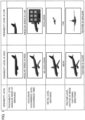
- Fig. 1 is a diagram showing examples of the viewability level.
- the viewability level represents the level of viewability when a video of a mobile object being captured by a movable camera is viewed on a monitor screen by an observer (referred to also as a "user").
- the viewability level can be evaluated based on one or more of a trackability level, an occlusion occurrence level, a detail level and a feature level. With the increase in the viewability level, the observer can more appropriately monitor the mobile object in the video displayed on the monitor screen.
- the trackability level is high when the angular speed of the swiveling of the movable camera is sufficiently high (i.e., when the movable camera is capable of keeping sight of the moving mobile object), and is low when the angular speed of the swiveling of the movable camera is low (i.e., when the movable camera is incapable of keeping sight of the moving mobile object and part or the whole of the mobile object disappears from the video).
- the viewability level is high when the trackability level is high, and the viewability level is low when the trackability level is low.
- the movable camera keeps sight of the moving mobile object means that the direction of the movable camera capable of swiveling (i.e., the image capturing direction) keeps pointing towards the mobile object.
- the "swiveling” includes horizontal swiveling (pan) and vertical swiveling (tilt).
- the occlusion occurrence level is low when no occlusion occurs (i.e., when no screening object exists between the movable camera and the moving mobile object) when the moving mobile object is tracked for a predetermined time, and is high when occlusion occurs (i.e., when a screening object exists between the movable camera and the moving mobile object and a blind spot is caused by the screening object) when the moving mobile object is tracked for a predetermined time. Further, the occlusion occurrence level becomes higher as an occlusion occurrence time becomes longer.
- the viewability level is high when the occlusion occurrence level is low, and the viewability level is low when the occlusion occurrence level is high.
- the detail level is high when the distance from the movable camera to the mobile object is short (i.e., when the mobile object is captured in a large size), and is low when the distance from the movable camera to the mobile object is long (i.e., when the mobile object is captured in a small size).
- the viewability level is high when the detail level is high, and the viewability level is low when the detail level is low.
- the feature level is determined based on from which direction the movable camera is capturing the image of the mobile object.
- the feature level is high when the image capturing direction of the movable camera is a direction for clearly grasping a feature of the mobile object (e.g., when the image of the mobile object is captured in a desirable image capturing direction predetermined for each type of the mobile object), and is low when the image capturing direction of the movable camera is a direction in which the feature of the mobile object is not grasped clearly (e.g., when the image of the mobile object is captured in a direction different from the predetermined desirable image capturing direction).
- the viewability level is high when the feature level is high, and the viewability level is low when the feature level is low.
- the desirable image capturing direction can also be a direction designated by an operation performed by the user.
- a description will be given of an example in which the viewability level is evaluated based on a combination of the trackability level and the feature level.
- a description will be given of an example in which the viewability level is evaluated based on a combination of the trackability level and the detail level.
- the viewability level may also be evaluated based on a different combination of the trackability level, the occlusion occurrence level, the detail level and the feature level. Specifically, the viewability level may also be evaluated based on any one of a combination of the trackability level and the occlusion occurrence level, a combination of the trackability level, the detail level and the feature level, a combination of the occlusion occurrence level and the detail level, a combination of the occlusion occurrence level and the feature level, a combination of the occlusion occurrence level, the detail level and the feature level, a combination of the trackability level, the occlusion occurrence level and the detail level, a combination of the trackability level, the occlusion occurrence level and the feature level, and a combination of the trackability level, the occlusion occurrence level, the detail level and the feature level.
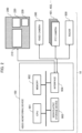
- Fig. 2 is a diagram showing a hardware configuration of a video monitoring device 100 and a video monitoring system 10 according to the first embodiment.
- the video monitoring system 10 includes the video monitoring device 100, a monitoring panel 200, one or more fixed cameras 300 each being a fixed camera for capturing a wide area, a plurality of PTZ cameras 401, ..., as movable cameras each for capturing a narrow area, and a radar 500 that detects the position of the mobile object.
- the monitoring panel 200 includes a wide area monitor screen 210, a narrow area monitor screen 220, and a user operation unit 230 (shown in Fig. 4 which will be explained later).
- the monitoring panel 200 may also be configured as a part of the video monitoring device 100.
- the video monitoring device 100 includes a processing circuit.
- the video monitoring device 100 is a computer, for example.
- the video monitoring device 100 includes a CPU (Central Processing Unit) 901 that is a processor as an information processing unit, a memory 902 as a storage device for storing a program, a nonvolatile storage device 903 such as a hard disk drive (HDD) or a solid state drive (SSD), and an interface 904.
- the memory 902 is, for example, a nonvolatile or volatile semiconductor memory such as a RAM (Random Access Memory), a ROM (Read Only Memory), a flash memory, an EPROM (Erasable Programmable Read Only Memory) or an EEPROM (Electrically Erasable Programmable Read Only Memory).
- the memory 902 stores a video monitoring program as software, for example.
- the CPU 901 is capable of executing a video monitoring method according to the first embodiment by executing the video monitoring program. Furthermore, it is also possible to implement part of functions of the video monitoring device 100 by dedicated hardware and other part of the functions by software or firmware.
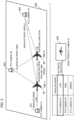
- Fig. 3 is a diagram showing an example of employing the video monitoring system 10 according to the first embodiment for monitoring an airplane traveling in an airport 600.
- the video monitoring system 10 includes the video monitoring device 100, the monitoring panel 200, the fixed camera 300, the plurality of PTZ cameras (#1 - #3) 401 - 403, and the radar 500 that detects the positions of airplanes M1 and M2 and the like as mobile objects traveling in the airport 600.
- the video monitoring device 100 displays videos from a plurality of fixed cameras 300 or a synthetic video of videos from a plurality of fixed cameras 300 on the wide area monitor screen 210.
- the video monitoring device 100 acquires position information indicating the position of the airplane M1 as a moving monitoring target based on a detection signal from the radar 500, commands image capturing directions D1, D2, D3 of the PTZ cameras (#1 - #3) 401 - 403 provided at predetermined positions, and evaluates (i.e., calculates) the viewability level of the mobile object in the video captured by each of the PTZ cameras (#1 - #3) 401 - 403 based on the position of the airplane M1 and the positions of the PTZ cameras (#1 - #3) 401 - 403.
- the video monitoring device 100 selects a PTZ camera for use for the image capturing of the airplane M1 from the PTZ cameras (#1 - #3) 401 - 403 based on the viewability level, and displays the video of the airplane M1 captured by the selected PTZ camera on the narrow area monitor screen 220.
- the airplane as the mobile object as the monitoring target is an airplane that has been designated by the observer through the user operation unit 230, for example.
- the viewability level is evaluated based on the angular speed of the swiveling of each of the PTZ cameras (#1 - #3) 401 - 403 necessary for each of the PTZ cameras (#1 - #3) 401 - 403 to keep sight of the mobile object.
- Fig. 4 is a functional block diagram schematically showing a configuration of the video monitoring device 100 and the video monitoring system 10 according to the first embodiment.
- the video monitoring device 100 includes an acquisition unit 110 that acquires the position information indicating the position of the airplane M1 as a moving mobile object, a command unit 120 that commands the image capturing directions of the plurality of PTZ cameras (#1 - #3) 401 - 403 provided at predetermined known positions, and an evaluation unit 130 that evaluates the viewability level of the airplane M1 in the video captured by each of the plurality of PTZ cameras (#1 - #3) 401 - 403 based on the position of the airplane M1 and the positions of the plurality of PTZ cameras (#1 - #3) 401 - 403.
- the video monitoring device 100 includes a selection unit 140 that selects a PTZ camera for use for the image capturing of the airplane M1 from the plurality of PTZ cameras (#1 - #3) 401 - 403 based on the viewability level and a display control unit 150 that displays the video of the airplane M1 captured by the selected PTZ camera on the narrow area monitor screen 220.
- the acquisition unit 110 acquires the position information on the airplane M1 based on the detection signal from the radar 500, it is also possible to detect the position of the mobile object or the like based on a video from a fixed camera 300 or a synthetic video (e.g., panoramic video, bird's-eye video or the like) of videos from a plurality of fixed cameras 300
- the evaluation unit 130 evaluates the viewability level based on the angular speed of the swiveling of each of the plurality of PTZ cameras (#1 - #3) 401 - 403 necessary for each of the plurality of PTZ cameras (#1 - #3) 401 - 403 to keep sight of the mobile object.
- the evaluation unit 130 judges that the viewability level is higher (i.e., the monitoring target is more easily viewable to the observer) with the decrease in the angular speed of the swiveling (i.e., with the increase in the trackability level).
- Fig. 5 is a diagram showing the trackability level as an example of the viewability level.
- Each of the PTZ cameras (#1 - #3) 401 - 403 swivels corresponding to the traveling distance per unit time (i.e., speed) of the airplane M1 as the mobile object as the monitoring target.
- the angular speed of the swiveling of the PTZ camera (#1) 401 is low.
- the angular speed of the swiveling of the PTZ camera (#2) 402 is high.
- the angular speed of the swiveling of the PTZ camera (#3) 403 is middle.
- the selection unit 140 sends the video from the PTZ camera (#1) 401, regarding which the angular speed of the swiveling is the lowest, to the display control unit 150 and thereby has the video from the PTZ camera (#1) 401 displayed on the narrow area monitor screen 220.
- Fig. 6A shows an example in which the angular speed of the swiveling of the PTZ camera (#1) 401 is sufficiently high and the trackability level is high
- Fig. 6B shows an example in which the angular speed of the swiveling of the PTZ camera (#2) 402 is low and the trackability level is low.
- the PTZ camera (#1) 401 has sight of the whole of the airplane M1 as the mobile object at time t1 and keeps sight of the whole of the airplane M1 also at time t2 after the elapse of a certain time period as shown in Fig. 6A .
- Fig. 6A shows an example in which the angular speed of the swiveling of the PTZ camera (#2) 402 is low and the trackability level is low.
- the PTZ camera (#1) 401 has sight of the whole of the airplane M1 as the mobile object at time t1 and keeps sight of the whole of the airplane M1 also at time t2 after the elapse of a certain
- the PTZ camera (#2) 402 in Fig. 5 having sight of the whole of the airplane M1 at the time t1 is not fast enough to keep track of the airplane M1 and loses sight of part of the airplane M1 at the time t2 after the elapse of the certain time period.
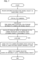
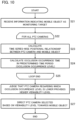
- Fig. 7 is a flowchart showing an operation of the video monitoring device according to the first embodiment.
- the acquisition unit 110 acquires the position information indicating the position of the mobile object as the moving monitoring target (in the first embodiment, an airplane traveling in the airport) (step S11).
- the evaluation unit 130 executes a process of calculating a time series-wise positional relationship between a PTZ camera and the mobile object (step S13) and calculating the angular speed of the swiveling of the PTZ camera necessary for keeping sight of the mobile object (step S14) for all of the plurality of PTZ cameras (steps S12 to S15).
- the "time series-wise positional relationship” is a positional relationship between the PTZ camera and the mobile object from a certain time point to a time point after the elapse of a certain time period.
- the evaluation unit 130 judges that a PTZ camera regarding which the angular speed of the swiveling is lower provides a higher viewability level (step S16).
- the command unit 120 directs a PTZ camera selected based on the viewability level towards the mobile object as the monitoring target (step S17). In this case, the command unit 120 selects a PTZ camera that provides the highest viewability level, for example.
- the video monitoring device 100 or the video monitoring method according to the first embodiment it is possible to preestimate the time series-wise positional relationship between the mobile object and each PTZ camera, select a video with the highest viewability to the observer from the videos captured by the plurality of PTZ cameras as a plurality of narrow area monitoring cameras based on the positional relationship, and display the selected video on the narrow area monitor screen 220.
- zapping as a phenomenon in which the video displayed on the narrow area monitor screen 220 is switched frequently, is unlikely to occur since the selection of the PTZ camera is made based on the time series-wise positional relationship between each PTZ camera and the mobile object.
- the second embodiment differs from the first embodiment in using the occlusion occurrence level as the viewability level. Except for this feature, the second embodiment is the same as the first embodiment. Thus, Fig. 1 and Fig. 2 are also referred to in the description of the second embodiment.
- Fig. 8 is a diagram showing an example of employing a video monitoring system according to the second embodiment for monitoring an airplane M1 traveling in an airport.
- the PTZ camera (#1) 401 swivels following the airplane M1 traveling in the airport, in which a screening object H1 such as a building causes occlusion for an occlusion occurrence time P1 during which the image capturing of the airplane M1 is impossible, and a screening object H2 such as a building causes occlusion for an occlusion occurrence time P2 during which the image capturing of the airplane M1 is impossible.
- a screening object H1 such as a building causes occlusion for an occlusion occurrence time P1 during which the image capturing of the airplane M1 is impossible
- a screening object H2 such as a building causes occlusion for an occlusion occurrence time P2 during which the image capturing of the airplane M1 is impossible.
- the PTZ camera (#2) 402 swivels following the airplane M1 traveling in the airport, in which a screening object H3 such as a building causes occlusion for an occlusion occurrence time P3 during which the image capturing of the airplane M1 is impossible.
- a screening object H3 such as a building causes occlusion for an occlusion occurrence time P3 during which the image capturing of the airplane M1 is impossible.
- P1 + P2 - 30 seconds and P3 15 seconds
- the PTZ camera (#2) 402 with the shorter occlusion occurrence time provides the higher viewability level, and thus the video from the PTZ camera (#2) 402 is automatically selected and displayed on the narrow area monitor screen 220.
- Fig. 9 is a functional block diagram schematically showing a configuration of a video monitoring device 100a and a video monitoring system 10a according to the second embodiment.
- each component identical or corresponding to a component shown in Fig. 4 is assigned the same reference character as in Fig. 4 .
- the video monitoring system 10a includes the video monitoring device 100a, the monitoring panel 200, the one or more fixed cameras 300, the plurality of PTZ cameras (#1 - #3) 401 - 403, and the radar 500 that detects the position of the airplane M1 as the mobile object traveling in the airport.
- the video monitoring device 100a displays a video from a fixed camera 300 or a synthetic video of videos from a plurality of fixed cameras 300 on the wide area monitor screen 210.
- the video monitoring device 100a acquires position information indicating the position of the airplane M1 moving on a taxiway, a runway or the like in the airport by using the radar 500, commands the image capturing directions of the PTZ cameras (#1 - #3) 401 - 403 provided at the predetermined positions, evaluates the viewability level of the airplane M1 in the video captured by each of the PTZ cameras (#1 - #3) 401 - 403 based on the position of the airplane M1 and the positions of the PTZ cameras (#1 - #3) 401 - 403, selects a PTZ camera for use for the image capturing of the airplane M1 from the PTZ cameras (#1 - #3) 401 - 403 based on the viewability level, and displays the video of the airplane M1 captured by the selected PTZ camera on the narrow area monitor screen 220.
- the airplane M1 as the mobile object as the monitoring target is designated by the observer through the user operation unit 230, for example.
- the viewability level is evaluated based on the occlusion occurrence level of each of the PTZ cameras (#1 - #3) 401 - 403.
- an evaluation unit 130a calculates the occlusion occurrence time based on position information and screening object information regarding each PTZ camera and selects the video to be displayed on the narrow area monitor screen 220 based on the occlusion occurrence level corresponding to the occlusion occurrence time.
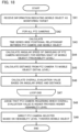
- Fig. 10 is a flowchart showing an operation of the video monitoring device 100a according to the second embodiment.
- the acquisition unit 110 acquires the position information indicating the position of the mobile object as the moving monitoring target (in the first embodiment, an airplane traveling in the airport) (step S21) .
- the evaluation unit 130 executes a process of calculating the time series-wise positional relationship between a PTZ camera and the mobile object (step S23) and calculating the occlusion occurrence time in a predetermined time period (step S24) for all of the plurality of PTZ cameras (steps S22 to S25).
- the evaluation unit 130 judges that a PTZ camera regarding which the occlusion occurrence level corresponding to the occlusion occurrence time is lower provides a higher viewability level (step S26).
- the command unit 120 directs a PTZ camera selected based on the viewability level towards the mobile object as the monitoring target (step S27). In this case, the command unit 120 selects a PTZ camera that provides the highest viewability level, for example.
- a video with the highest viewability to the observer selected from the plurality of videos captured by the plurality of PTZ cameras as the plurality of narrow area monitoring cameras, can be displayed on the narrow area monitor screen 220.
- the zapping as the phenomenon in which the video displayed on the narrow area monitor screen 220 is switched frequently, is unlikely to occur since the selection of the PTZ camera is made based on the time series-wise positional relationship between each PTZ camera and the mobile object.
- the third embodiment differs from the first embodiment in using the trackability level and the feature level as the viewability level. Except for this feature, the third embodiment is the same as the first embodiment. Thus, Fig. 1 and Fig. 2 are also referred to in the description of the third embodiment.
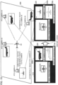
- Fig. 11 is a diagram showing examples of the feature level as the viewability level.
- the evaluation unit automatically selects a PTZ camera having an image capturing direction vector similar to the vector V, and has the video from the automatically selected PTZ camera displayed on the narrow area monitor screen 220.
- the feature level is calculated as a similarity level between the vector V of the desired image capturing direction and the image capturing direction vector V1 - V4 of each PTZ camera, for example.
- the vector V3 among the image capturing direction vectors V1 - V4 is the most similar to the vector V of the desired image capturing direction, and thus the PTZ camera (#3) 403 is automatically selected.
- the vector V may also be previously determined depending on the type of the mobile object. Further, the vector V may also be determined according to a command inputted by the observer.
- Fig. 12 is a functional block diagram schematically showing a configuration of a video monitoring device 100b and a video monitoring system 10b according to the third embodiment.
- each component identical or corresponding to a component shown in Fig. 4 is assigned the same reference character as in Fig. 4 .
- an evaluation unit 130b calculates the trackability level and the feature level based on viewpoint designation information and the position information regarding each PTZ camera, and selects the video to be displayed on the narrow area monitor screen 220 based on an overall evaluation value as a combination of the trackability level and the feature level.
- the overall evaluation value is calculated by weighted addition of the trackability level and the feature level, for example.
- Fig. 13 is a flowchart showing an operation of the video monitoring device 100b according to the third embodiment.
- the acquisition unit 110 acquires the position information indicating the position of the mobile object as the moving target object (in the third embodiment, an airplane traveling in the airport) (step S31) .
- the evaluation unit 130 executes a process of calculating the time series-wise positional relationship between a PTZ camera and the mobile object (step S33), calculating the angular speed of the swiveling of the PTZ camera necessary for keeping sight of the mobile object (step S34), calculating the feature level of the mobile object (step S35), and calculating the overall evaluation value (step S36) for all of the plurality of PTZ cameras (steps S32 to S37).
- the evaluation unit 130 judges that a PTZ camera regarding which the overall evaluation value is higher provides a higher viewability level (step S38).
- the command unit 120 directs a PTZ camera selected based on the viewability level towards the mobile object as the monitoring target (step S39). In this case, the command unit 120 selects a PTZ camera that provides the highest viewability level, for example.
- Fig. 14 is a diagram showing a viewpoint designation operation executed by the video monitoring system 10b according to the third embodiment.
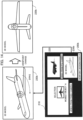
- the vector V of the image capturing direction is inputted by dragging the display on the narrow area monitor screen 220 of a monitoring panel 200b so as to rotate a three-dimensional model (i.e., 3D model) of the airplane viewed obliquely from the front in the video and have a rear part of the airplane 3D model displayed in the video.
- This operation may also be performed by using a user operation unit 230b such as a mouse, a switch or a touch panel.
- Fig. 15 is a diagram showing the viewpoint designation operation executed by the video monitoring system 10b according to the third embodiment and the videos captured by the PTZ cameras.
- Fig. 15 shows a state in which the vector V of the image capturing direction is inputted by dragging the display on the narrow area monitor screen 220 so as to rotate the 3D model of the airplane in the video and have the rear part of the airplane 3D model displayed in the video as illustrated, in which the video from the PTZ camera (#3) was displayed on the narrow area monitor screen 220 before a viewpoint change operation through a viewpoint change I/F, whereas the video from the PTZ camera (#1) is displayed on the narrow area monitor screen 220 after the viewpoint change operation through the viewpoint change I/F.
- a video with the highest viewability to the observer selected from the plurality videos captured by the plurality of PTZ cameras as the plurality of narrow area monitoring cameras, can be automatically displayed on the narrow area monitor screen 220.
- a designated video can be displayed on the narrow area monitor screen 220.
- the fourth embodiment differs from the first embodiment in using the trackability level and the detail level as the viewability level. Except for this feature, the fourth embodiment is the same as the first embodiment. Thus, Fig. 1 and Fig. 2 are also referred to in the description of the fourth embodiment.
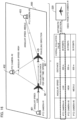
- Fig. 16 is a diagram showing an example of employing a video monitoring system according to the fourth embodiment for monitoring an airplane M1 traveling in an airport.
- Each of the PTZ cameras (#1 - #3) 401 - 403 swivels corresponding to the traveling distance per unit time (i.e., speed) of the airplane M1 as the mobile object as the monitoring target.
- the angular speed of the swiveling of the PTZ camera (#1) 401 is low.
- the angular speed of the swiveling of the PTZ camera (#2) 402 is high.
- the angular speed of the swiveling of the PTZ camera (#3) 403 is middle.
- the distance from the PTZ camera (#1) 401 to the airplane M1 is 300 m
- the distance from the PTZ camera (#2) 402 to the airplane is 300 m
- the distance from the PTZ camera (#3) 403 to the airplane M1 is 600 m.
- the PTZ camera (#1) 401 is the highest.
- the selection unit 140 sends the video from the PTZ camera (#1) 401 regarding which the angular speed of the swiveling is the lowest, to the display control unit 150 and thereby has the video from the PTZ camera (#1) 401 displayed on the narrow area monitor screen 220.
- Fig. 17 is a functional block diagram schematically showing a configuration of a video monitoring device 100c and a video monitoring system 10c according to the fourth embodiment.
- each component identical or corresponding to a component shown in Fig. 4 is assigned the same reference character as in Fig. 4 .
- an evaluation unit 130c calculates the trackability level and the detail level based on the position information regarding each PTZ camera, and selects the video to be displayed on the narrow area monitor screen 220 based on the overall evaluation value as a combination of the trackability level and the detail level.
- Fig. 18 is a flowchart showing an operation of the video monitoring device according to the fourth embodiment.
- the acquisition unit 110 acquires the position information indicating the position of the mobile object as the moving target object (in the fourth embodiment, an airplane traveling in the airport) (step S41) .
- the evaluation unit 130 executes a process of calculating the time series-wise positional relationship between a PTZ camera and the mobile object (step S43), calculating the angular speed of the swiveling of the PTZ camera necessary for keeping sight of the mobile object (step S44), calculating the detail level of the mobile object (step S45), and calculating the overall evaluation value (step S46) for all of the plurality of PTZ cameras (steps S42 to S47).
- the evaluation unit 130 judges that a PTZ camera regarding which the overall evaluation value is higher provides a higher viewability level (step S48).
- the command unit 120 directs a PTZ camera selected based on the viewability level towards the mobile object as the monitoring target (step S49). In this case, the command unit 120 selects a PTZ camera that provides the highest viewability level, for example.
- a video with the highest viewability to the observer selected from the plurality of videos captured by the plurality of PTZ cameras as the plurality of narrow area monitoring cameras, can be automatically displayed on the narrow area monitor screen 220.
- the mobile object is an airplane and video monitoring systems for monitoring an airplane traveling in an airport.
- the mobile object is not limited to an airplane.
- the mobile object can also be an automobile traveling on a road, a marine vessel moving on the water, an airplane flying in the air, a person walking on a passage, or the like.
- the viewability level is determined based on one of the trackability level, the occlusion occurrence level, the detail level and the feature level or the overall evaluation value obtained by the weighted addition of two or more of these values, and the PTZ camera for use for tracking the mobile object is determined.
- the video monitoring device may also be configured to be able to change which one of the trackability level, the occlusion occurrence level, the detail level, the feature level and combinations of some of these values should be used for evaluating the viewability level based on a user operation or the type of the mobile object.
- the video monitoring device may evaluate the viewability level based on the occlusion occurrence level when the mobile object as the monitoring target is an airplane traveling in an airport and evaluate the viewability level based on the trackability level when the mobile object as the monitoring target is an airplane flying in the air.
- the video monitoring system may also be configured to include a plurality of narrow area monitor screens 220. In such cases, a plurality of videos may be displayed in descending order of the viewability level.
- 10, 10a - 10c video monitoring system, 100, 100a - 100c: video monitoring device, 110: acquisition unit, 120: command unit, 130, 130a - 130c: evaluation unit, 140: selection unit, 150: display control unit, 160: viewpoint designation unit, 200, 200b: monitoring panel, 210: wide area monitor screen, 220: narrow area monitor screen (monitor screen), 230, 230b: user operation unit, 300: fixed camera, 401 - 403: PTZ camera (movable camera), 500, radar, 600: airport, D1 - D3: image capturing direction, M1, M2: airplane (mobile object), H1 - H3: screening object.
- PTZ camera movable camera
Landscapes
- Engineering & Computer Science (AREA)
- Multimedia (AREA)
- Theoretical Computer Science (AREA)
- Physics & Mathematics (AREA)
- General Physics & Mathematics (AREA)
- Computer Vision & Pattern Recognition (AREA)
- Signal Processing (AREA)
- Computing Systems (AREA)
- Artificial Intelligence (AREA)
- Databases & Information Systems (AREA)
- Evolutionary Computation (AREA)
- General Health & Medical Sciences (AREA)
- Medical Informatics (AREA)
- Software Systems (AREA)
- Health & Medical Sciences (AREA)
- Closed-Circuit Television Systems (AREA)
- Studio Devices (AREA)
Applications Claiming Priority (1)
| Application Number | Priority Date | Filing Date | Title |
|---|---|---|---|
| PCT/JP2021/006571 WO2022176189A1 (ja) | 2021-02-22 | 2021-02-22 | 映像監視装置、映像監視システム、映像監視方法、及び映像監視プログラム |
Publications (2)
| Publication Number | Publication Date |
|---|---|
| EP4283984A1 true EP4283984A1 (de) | 2023-11-29 |
| EP4283984A4 EP4283984A4 (de) | 2024-03-13 |
Family
ID=81291872
Family Applications (1)
| Application Number | Title | Priority Date | Filing Date |
|---|---|---|---|
| EP21926619.4A Pending EP4283984A4 (de) | 2021-02-22 | 2021-02-22 | Videomonitorvorrichtung, videomonitorsystem, videomonitorverfahren und videomonitorprogramm |
Country Status (5)
| Country | Link |
|---|---|
| US (1) | US12592078B2 (de) |
| EP (1) | EP4283984A4 (de) |
| JP (1) | JP7058806B1 (de) |
| CN (1) | CN116965012A (de) |
| WO (1) | WO2022176189A1 (de) |
Families Citing this family (1)
| Publication number | Priority date | Publication date | Assignee | Title |
|---|---|---|---|---|
| JP2023176536A (ja) * | 2022-05-31 | 2023-12-13 | キヤノン株式会社 | 情報処理装置、その制御方法ならびにプログラム |
Family Cites Families (19)
| Publication number | Priority date | Publication date | Assignee | Title |
|---|---|---|---|---|
| JP2001094975A (ja) * | 1999-09-20 | 2001-04-06 | Hitachi Ltd | 移動物体追跡方法および装置 |
| GB2368482B (en) * | 2000-10-26 | 2004-08-25 | Hewlett Packard Co | Optimal image capture |
| JP2005142683A (ja) | 2003-11-04 | 2005-06-02 | Matsushita Electric Ind Co Ltd | カメラ制御装置およびカメラ制御方法 |
| JP2006270404A (ja) * | 2005-03-23 | 2006-10-05 | Mitsubishi Electric Corp | 撮影制御装置、撮影制御方法および撮影制御プログラム |
| DE602007007576D1 (de) * | 2007-03-30 | 2010-08-19 | Abb Research Ltd | Verfahren zum Betrieb ferngesteuerter Kameras in einem industriellen Verfahren |
| JP2008301191A (ja) * | 2007-05-31 | 2008-12-11 | Victor Co Of Japan Ltd | 映像監視システム、映像監視制御装置、映像監視制御方法、及び映像監視制御用プログラム |
| US10896327B1 (en) * | 2013-03-15 | 2021-01-19 | Spatial Cam Llc | Device with a camera for locating hidden object |
| KR101666397B1 (ko) * | 2010-12-21 | 2016-10-14 | 한국전자통신연구원 | 객체 영상 획득 장치 및 방법 |
| JP2013223104A (ja) | 2012-04-17 | 2013-10-28 | Panasonic Corp | カメラおよびカメラシステム |
| WO2014148394A1 (ja) * | 2013-03-19 | 2014-09-25 | 株式会社日立国際電気 | 画像表示装置および画像表示方法 |
| JP2015213251A (ja) * | 2014-05-02 | 2015-11-26 | 株式会社Ihi | 挙動解析装置、監視システム及びアミューズメントシステム |
| JP6469975B2 (ja) * | 2014-06-27 | 2019-02-13 | 株式会社 日立産業制御ソリューションズ | 映像監視装置、映像監視システムおよび映像監視方法 |
| JP6413530B2 (ja) * | 2014-09-12 | 2018-10-31 | 沖電気工業株式会社 | 監視システム、映像解析装置、映像解析方法およびプログラム |
| JP6458474B2 (ja) * | 2014-12-10 | 2019-01-30 | 沖電気工業株式会社 | 監視システム、映像解析装置、映像解析方法およびプログラム |
| JP2016127571A (ja) * | 2015-01-08 | 2016-07-11 | キヤノン株式会社 | カメラシステム、表示制御装置、表示制御方法、及びプログラム |
| JP6679357B2 (ja) * | 2016-03-17 | 2020-04-15 | セコム株式会社 | 飛行物体監視システム |
| CN109325967B (zh) * | 2018-09-14 | 2023-04-07 | 腾讯科技(深圳)有限公司 | 目标跟踪方法、装置、介质以及设备 |
| EP3839910B1 (de) * | 2019-12-19 | 2023-01-25 | Axis AB | Priorisierung unter kameras einer multikameraanordnung |
| WO2021133918A1 (en) * | 2019-12-23 | 2021-07-01 | AirSelfie, Inc. | Aerial camera device, systems, and methods |
-
2021
- 2021-02-22 EP EP21926619.4A patent/EP4283984A4/de active Pending
- 2021-02-22 WO PCT/JP2021/006571 patent/WO2022176189A1/ja not_active Ceased
- 2021-02-22 CN CN202180093569.5A patent/CN116965012A/zh active Pending
- 2021-02-22 JP JP2021538825A patent/JP7058806B1/ja active Active
-
2023
- 2023-06-28 US US18/215,428 patent/US12592078B2/en active Active
Also Published As
| Publication number | Publication date |
|---|---|
| JP7058806B1 (ja) | 2022-04-22 |
| WO2022176189A1 (ja) | 2022-08-25 |
| EP4283984A4 (de) | 2024-03-13 |
| US20230343103A1 (en) | 2023-10-26 |
| US12592078B2 (en) | 2026-03-31 |
| JPWO2022176189A1 (de) | 2022-08-25 |
| CN116965012A (zh) | 2023-10-27 |
Similar Documents
| Publication | Publication Date | Title |
|---|---|---|
| US11228715B2 (en) | Video surveillance system and video surveillance method | |
| JP4730431B2 (ja) | 目標追尾装置 | |
| JP6696615B2 (ja) | 監視システム、監視方法、及び監視プログラムを記憶する記録媒体 | |
| US6771306B2 (en) | Method for selecting a target in an automated video tracking system | |
| EP3084577B1 (de) | Auswahl und verfolgung von objekten zur anzeige der partitionierung und gruppierung von videorahmen | |
| US7385626B2 (en) | Method and system for performing surveillance | |
| JP4694589B2 (ja) | 自動監視システム | |
| US20100013917A1 (en) | Method and system for performing surveillance | |
| US20100201787A1 (en) | Continuous geospatial tracking system and method | |
| Sommerlade et al. | Information-theoretic active scene exploration | |
| US20040263625A1 (en) | Camera-linked surveillance system | |
| JP2014036414A (ja) | 監視システム | |
| JP2007510322A (ja) | 監視ビデオの変化をサーチするためのシステム及び方法 | |
| US20150029332A1 (en) | Controlling movement of a camera to autonomously track a mobile object | |
| WO2014136499A1 (ja) | 監視装置、監視方法および撮像部の配置方法 | |
| GB2499427A (en) | Video tracking apparatus having two cameras mounted on a moveable unit | |
| US12592078B2 (en) | Video monitoring device, video monitoring system, video monitoring method, and storage medium storing video monitoring program | |
| JP6660192B2 (ja) | 飛行物体監視システム | |
| KR102119215B1 (ko) | 영상 표시 방법 및 컴퓨터 프로그램, 그 기록매체 | |
| JP7332047B2 (ja) | 追跡装置、追跡システム、追跡方法、およびプログラム | |
| JP5177068B2 (ja) | 目標追尾装置、目標追尾方法 | |
| JP2011145730A (ja) | 監視画面表示制御装置 | |
| JP4664878B2 (ja) | 画像処理装置 | |
| JP2005236508A (ja) | 自動追尾装置及び自動追尾方法 | |
| KR101445361B1 (ko) | 현장 모니터링 장치 |
Legal Events
| Date | Code | Title | Description |
|---|---|---|---|
| STAA | Information on the status of an ep patent application or granted ep patent |
Free format text: STATUS: THE INTERNATIONAL PUBLICATION HAS BEEN MADE |
|
| PUAI | Public reference made under article 153(3) epc to a published international application that has entered the european phase |
Free format text: ORIGINAL CODE: 0009012 |
|
| STAA | Information on the status of an ep patent application or granted ep patent |
Free format text: STATUS: REQUEST FOR EXAMINATION WAS MADE |
|
| 17P | Request for examination filed |
Effective date: 20230816 |
|
| AK | Designated contracting states |
Kind code of ref document: A1 Designated state(s): AL AT BE BG CH CY CZ DE DK EE ES FI FR GB GR HR HU IE IS IT LI LT LU LV MC MK MT NL NO PL PT RO RS SE SI SK SM TR |
|
| A4 | Supplementary search report drawn up and despatched |
Effective date: 20240213 |
|
| RIC1 | Information provided on ipc code assigned before grant |
Ipc: H04N 23/90 20230101ALI20240207BHEP Ipc: H04N 23/695 20230101ALI20240207BHEP Ipc: G06T 7/292 20170101ALI20240207BHEP Ipc: H04N 7/18 20060101AFI20240207BHEP |
|
| DAV | Request for validation of the european patent (deleted) | ||
| DAX | Request for extension of the european patent (deleted) | ||
| STAA | Information on the status of an ep patent application or granted ep patent |
Free format text: STATUS: EXAMINATION IS IN PROGRESS |
|
| 17Q | First examination report despatched |
Effective date: 20250623 |
|
| GRAP | Despatch of communication of intention to grant a patent |
Free format text: ORIGINAL CODE: EPIDOSNIGR1 |
|
| STAA | Information on the status of an ep patent application or granted ep patent |
Free format text: STATUS: GRANT OF PATENT IS INTENDED |