EP4283322B1 - Magnetresonanzbildgebungsvorrichtung und bildgebungspositionsbestimmungsverfahren - Google Patents
Magnetresonanzbildgebungsvorrichtung und bildgebungspositionsbestimmungsverfahren Download PDFInfo
- Publication number
- EP4283322B1 EP4283322B1 EP23174467.3A EP23174467A EP4283322B1 EP 4283322 B1 EP4283322 B1 EP 4283322B1 EP 23174467 A EP23174467 A EP 23174467A EP 4283322 B1 EP4283322 B1 EP 4283322B1
- Authority
- EP
- European Patent Office
- Prior art keywords
- imaging
- range
- subject
- magnetic resonance
- unit
- Prior art date
- Legal status (The legal status is an assumption and is not a legal conclusion. Google has not performed a legal analysis and makes no representation as to the accuracy of the status listed.)
- Active
Links
Images





Classifications
-
- A—HUMAN NECESSITIES
- A61—MEDICAL OR VETERINARY SCIENCE; HYGIENE
- A61B—DIAGNOSIS; SURGERY; IDENTIFICATION
- A61B5/00—Measuring for diagnostic purposes; Identification of persons
- A61B5/05—Detecting, measuring or recording for diagnosis by means of electric currents or magnetic fields; Measuring using microwaves or radio waves
- A61B5/055—Detecting, measuring or recording for diagnosis by means of electric currents or magnetic fields; Measuring using microwaves or radio waves involving electronic [EMR] or nuclear [NMR] magnetic resonance, e.g. magnetic resonance imaging
-
- G—PHYSICS
- G01—MEASURING; TESTING
- G01R—MEASURING ELECTRIC VARIABLES; MEASURING MAGNETIC VARIABLES
- G01R33/00—Arrangements or instruments for measuring magnetic variables
- G01R33/20—Arrangements or instruments for measuring magnetic variables involving magnetic resonance
- G01R33/44—Arrangements or instruments for measuring magnetic variables involving magnetic resonance using nuclear magnetic resonance [NMR]
- G01R33/48—NMR imaging systems
- G01R33/54—Signal processing systems, e.g. using pulse sequences ; Generation or control of pulse sequences; Operator console
- G01R33/543—Control of the operation of the MR system, e.g. setting of acquisition parameters prior to or during MR data acquisition, dynamic shimming, use of one or more scout images for scan plane prescription
-
- G—PHYSICS
- G01—MEASURING; TESTING
- G01R—MEASURING ELECTRIC VARIABLES; MEASURING MAGNETIC VARIABLES
- G01R33/00—Arrangements or instruments for measuring magnetic variables
- G01R33/20—Arrangements or instruments for measuring magnetic variables involving magnetic resonance
- G01R33/44—Arrangements or instruments for measuring magnetic variables involving magnetic resonance using nuclear magnetic resonance [NMR]
- G01R33/48—NMR imaging systems
- G01R33/54—Signal processing systems, e.g. using pulse sequences ; Generation or control of pulse sequences; Operator console
- G01R33/56—Image enhancement or correction, e.g. subtraction or averaging techniques, e.g. improvement of signal-to-noise ratio and resolution
- G01R33/567—Image enhancement or correction, e.g. subtraction or averaging techniques, e.g. improvement of signal-to-noise ratio and resolution gated by physiological signals, i.e. synchronization of acquired MR data with periodical motion of an object of interest, e.g. monitoring or triggering system for cardiac or respiratory gating
- G01R33/5673—Gating or triggering based on a physiological signal other than an MR signal, e.g. ECG gating or motion monitoring using optical systems for monitoring the motion of a fiducial marker
-
- G—PHYSICS
- G01—MEASURING; TESTING
- G01R—MEASURING ELECTRIC VARIABLES; MEASURING MAGNETIC VARIABLES
- G01R33/00—Arrangements or instruments for measuring magnetic variables
- G01R33/20—Arrangements or instruments for measuring magnetic variables involving magnetic resonance
- G01R33/44—Arrangements or instruments for measuring magnetic variables involving magnetic resonance using nuclear magnetic resonance [NMR]
- G01R33/48—NMR imaging systems
-
- G—PHYSICS
- G01—MEASURING; TESTING
- G01R—MEASURING ELECTRIC VARIABLES; MEASURING MAGNETIC VARIABLES
- G01R33/00—Arrangements or instruments for measuring magnetic variables
- G01R33/20—Arrangements or instruments for measuring magnetic variables involving magnetic resonance
- G01R33/44—Arrangements or instruments for measuring magnetic variables involving magnetic resonance using nuclear magnetic resonance [NMR]
- G01R33/48—NMR imaging systems
- G01R33/54—Signal processing systems, e.g. using pulse sequences ; Generation or control of pulse sequences; Operator console
- G01R33/546—Interface between the MR system and the user, e.g. for controlling the operation of the MR system or for the design of pulse sequences
-
- G—PHYSICS
- G01—MEASURING; TESTING
- G01R—MEASURING ELECTRIC VARIABLES; MEASURING MAGNETIC VARIABLES
- G01R33/00—Arrangements or instruments for measuring magnetic variables
- G01R33/20—Arrangements or instruments for measuring magnetic variables involving magnetic resonance
- G01R33/44—Arrangements or instruments for measuring magnetic variables involving magnetic resonance using nuclear magnetic resonance [NMR]
- G01R33/48—NMR imaging systems
- G01R33/54—Signal processing systems, e.g. using pulse sequences ; Generation or control of pulse sequences; Operator console
- G01R33/56—Image enhancement or correction, e.g. subtraction or averaging techniques, e.g. improvement of signal-to-noise ratio and resolution
- G01R33/565—Correction of image distortions, e.g. due to magnetic field inhomogeneities
- G01R33/56509—Correction of image distortions, e.g. due to magnetic field inhomogeneities due to motion, displacement or flow, e.g. gradient moment nulling
-
- G—PHYSICS
- G01—MEASURING; TESTING
- G01R—MEASURING ELECTRIC VARIABLES; MEASURING MAGNETIC VARIABLES
- G01R33/00—Arrangements or instruments for measuring magnetic variables
- G01R33/20—Arrangements or instruments for measuring magnetic variables involving magnetic resonance
- G01R33/44—Arrangements or instruments for measuring magnetic variables involving magnetic resonance using nuclear magnetic resonance [NMR]
- G01R33/48—NMR imaging systems
- G01R33/54—Signal processing systems, e.g. using pulse sequences ; Generation or control of pulse sequences; Operator console
- G01R33/56—Image enhancement or correction, e.g. subtraction or averaging techniques, e.g. improvement of signal-to-noise ratio and resolution
- G01R33/567—Image enhancement or correction, e.g. subtraction or averaging techniques, e.g. improvement of signal-to-noise ratio and resolution gated by physiological signals, i.e. synchronization of acquired MR data with periodical motion of an object of interest, e.g. monitoring or triggering system for cardiac or respiratory gating
Definitions
- the present disclosure relates to a magnetic resonance imaging (MRI) apparatus that measures a nuclear magnetic resonance (hereinafter, referred to as "NMR") signal, from hydrogen, phosphorus, and others, within a subject, and makes images of a nuclear density distribution and a relaxation-time distribution, for example.
- MRI magnetic resonance imaging
- NMR nuclear magnetic resonance
- the present disclosure relates to a technique for determining a position where the imaging is performed on the subject.
- an anatomically-determined cross section is imaged for each examination site, but the body shape and posture of a subject vary from one examination to another. Therefore, even in the case where the same imaging sequence is performed or analysis processing is performed, it is necessary to adjust the imaging position of the subject every time the examination is performed.
- the abdomen is a region where the subject's individual difference is large.
- the breath-hold imaging the position of the organ is also changed due to a respiratory phase, and this makes the degree of difficulty higher in setting the imaging position of the subject. From the viewpoint of reducing the burden on the subject, there is a tendency to reduce the breath-hold imaging. In this case, however, the organ position may also vary due to the breathing. Thus, setting the imaging position of the subject considering also the breathing is more difficult, and operator-to-operator variation may further be increased.
- imaging parameters need to be adjusted in accordance with the examination purpose. Therefore, if the setting of the imaging position is inappropriate and causes faulty settings, insufficient imaging range, and occurrence of artifacts associated therewith, re-imaging is to be performed and this increases the burden on the user.
- Patent Literature 1 JP Patent No. 5660807 discloses a technique in which a liver is targeted, and an edge of the organ is tracked on the basis of an edgeenhanced image, thereby automatically detecting and setting the imaging position.
- the organ position is automatically calculated only from the acquired image, and the variation of the organ position due to the subject's breathing is not taken into consideration. Therefore, in the technique of Patent Literature 1, a deviation may occur between the image used for detecting the imaging position and the actual breath-hold imaging position, and failures in imaging are unavoidable due to the variation of the organ position in the subject. In addition, it is necessary to perform the breath-hold imaging in order to control the respiratory motion during imaging, and this causes a large burden on the subject.
- US 2013/154646 A1 discloses a magnetic resonance imaging apparatus configured to determine imaging ranges for scanning a beating heart of a patient.
- US 2014/024924 A1 discloses a magnetic resonance imaging apparatus configured to determine an imaging position in the context of respiratory motion.
- An object of the present disclosure is to provide a technique for automatically setting an imaging position considering the respiratory motion of the subject, thereby reducing the burden on the user and enabling robust imaging against variations of the organ position.
- an MRI apparatus of the present invention is defined in claim 1.
- the user is allowed to select the breathing method at the time of imaging, as the imaging condition, and this enables automatic setting of an optimum position and range for the selected breathing method.
- the MRI apparatus comprises an imaging unit configured to acquire an image of a subject based on nuclear magnetic resonance, an imaging position determination unit configured to calculate an imaging range of the subject and to determine an imaging position, and a measurement control unit configured to control the imaging unit to perform a scout scan including acquisition of a moving image comprising multiple image frames of one or more cycles of a periodic motion of the subject.
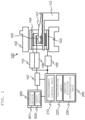
- FIG. 1 shows a configuration of a typical MRI apparatus to which the present embodiment is applied.
- the MRI apparatus comprises an imaging unit 100 including a magnet 102 configured to generate a static magnetic field in a space (examination space) where the subject 101 is placed, a gradient coil 103 configured to generate a gradient magnetic field in the examination space, an RF coil 104 configured to generate an RF magnetic field in a predetermined region of the subject 101, and an RF probe 105 configured to detect MR signals generated by the subject 101, and a computer 200 configured to perform various calculations and others required for controlling the imaging unit 100 and imaging by the imaging unit 100.
- the computer 200 has functions such as a measurement control unit 210 configured to control the imaging unit 100, a calculation unit 220 configured to perform calculations such as image generation, and an imaging position determination unit 230 configured to perform various calculations related to the imaging position determination.
- the computer 200 is also connected to a UI unit 300 provided with a display device 301 and an input device 302 for interfacing with a user.
- the MRI apparatus is further provided with a table 112 for placing the subject in the examination space.
- the gradient coil 103 is made up of gradient coils in three directions of X, Y, and Z, and generates gradient magnetic fields, respectively, in response to signals from a gradient power supply 109.
- the RF coil 104 generates an RF magnetic field in response to signals from an RF transmitter 110.
- a signal detector 106 detects the signals from the RF probe 105, and a signal processor 107 processes the signals and converts them into image signals by computation.
- the gradient magnetic field power supply 109, the RF transmitter 110, and the signal detector 106 perform imaging according to a time chart called a pulse sequence.
- a nuclear magnetic resonance phenomenon is generated in the nuclei of atoms constituting a tissue of the subject, and nuclear magnetic resonance signals (echo signals) emitted from the subject are detected as a response.
- the gradient magnetic fields in the respective directions are combined appropriately, thereby providing different phase encoding to the echo signals, and the signal detector 106 collects the echo signals respectively obtained by the different phase encoding.
- values such as 128, 256, and 512 are usually selected per image.
- Each echo signal is typically obtained as a time-series signal consisting of 128, 256, 512, and 1024 sampling data items.
- the computer 200 performs two-dimensional Fourier transform on these sampling data items to generate one MR image, and displays the image on the display device 301.
- the computer 200 is provided with a memory, a CPU, and a GPU, and functions of the measurement control unit 210, the calculation unit (image generation/image processing) 220, and the imaging position determination unit 230 are executed by the CPU and others uploading programs for implementing the functions.
- some of the functions implemented by the computer 200 may also include the functions implemented by a programmable IC such as ASIC and FPGA, and these are also treated as a part of the computer 200.
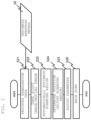
- FIG. 2 is a flowchart showing the control performed by the measurement control unit 210.
- examination data is registered (S21) and then a scout image is taken (S22).
- the examination data includes information regarding the subject, an examination site (target disease), and examination protocols (imaging types, the order of imaging, and others).
- the examination data may be entered by a user via the user interface, or the examination data may be read in, which is stored in advance in a medium such as a recording medium.
- the scout image is a relatively low-resolution image targeted for a wide range of the subject to determine the imaging position.
- the scout image may be a 2D image or a moving image acquired over at least one cycle of the periodic motion of the subject.
- the 2D image is distinguished from the moving image, and it is referred to as a 2D scout image.
- the imaging position determination unit 230 automatically calculates the imaging range using the scout image (S23) and performs positioning (imaging range adjustment) on the scout image (S24).
- the automatic calculation of the imaging range and the adjustment thereof will be described in detail in the following embodiments.
- parameters are adjusted manually or within the system as needed (S25), and then main scanning for the examination is performed (S26).
- the parameters to be adjusted (S25) are mainly imaging parameters for determining the pulse sequence, such as a slice thickness, a slice number, a matrix size, and the repetition time TR, and the parameter adjustment is executed when it is required in accordance with the adjustment of the imaging range.
- the MRI apparatus of the present embodiment features that the imaging position determination unit 230 uses the scout image acquired by the imaging unit 100 to calculate multiple imaging ranges including a minimum imaging range embracing a predetermined tissue, and a maximum imaging range embracing a range in which the tissue is displaced within a cycle of the periodic motion. Then, according to the imaging conditions, any one of the multiple imaging ranges is determined as the imaging position for the main imaging.
- the processing of the imaging position setting unit 230 will be described.
- the portion where the respiratory motion occurs is mainly the abdomen, and the case where the Scanning region is the abdomen will be described as an example.
- each of the 2D scout image and the moving image is used in order to set an appropriate imaging position according to the imaging conditions, at the site where the respiratory motion occurs. From these images, the imaging position of the subject and the variation of the position are estimated, and the multiple imaging ranges are calculated using the thus estimated results. Further, based on the calculated imaging ranges, there are determined the user's desired imaging range, a position for acquiring a navigator echo, and others, in response to the imaging method associated with the respiratory motion.
- the imaging position determination unit 230 of the present embodiment comprises a tissue extraction unit configured to extract an organ as an imaging target using the image acquired by the scout scan, a phase calculation unit configured to calculate a phase of the periodic motion of the subject using the moving image, and an imaging range calculation unit configured to calculate multiple imaging ranges including a minimum imaging range and a maximum imaging range, using the organ position extracted by the tissue extraction unit and the phase of the periodic motion calculated by the phase calculation unit, and according to imaging conditions, the imaging position determination unit 230 determines any one of the multiple imaging ranges, as the imaging position for the main scanning.
- FIG. 3 shows an example of a functional block diagram of the imaging position determination unit 230.
- the imaging position determination unit 230 includes a pre-processing unit 231 configured to perform a pre-processing such as filtering on an image, a tissue extraction unit 233 configured to extract a desired Scanning region from the image after pre-processing, an imaging range calculation unit 235 configured to calculate an imaging range from the extracted Scanning region, a respiratory phase calculation unit 237 configured to calculate a respiratory phase based on the Scanning region with respect to each time-phase, extracted from the moving image, and a navigator position determination unit 239.
- a pre-processing unit 231 configured to perform a pre-processing such as filtering on an image
- tissue extraction unit 233 configured to extract a desired Scanning region from the image after pre-processing
- an imaging range calculation unit 235 configured to calculate an imaging range from the extracted Scanning region
- a respiratory phase calculation unit 237 configured to calculate a respiratory phase based on the Scanning region with respect to each
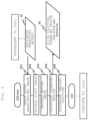
- designation of the breathing method 20 for the subject is accepted via the UI unit 300, as one of the imaging conditions (S41) ( FIG. 2 : S21).
- the breathing method is either breath holding or natural breathing, and the user decides the breathing method, considering the state of the subject, the imaging method, and others.
- the designation of the breathing method for the subject determines the imaging method in accordance with the breathing method.
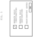
- FIG. 5 shows an example of a screen for accepting the designation of the breathing method for the subject, which is displayed on the display device 301.
- a selection of the breath-hold imaging or the respiratory gated imaging is acceptable.
- a selection from the following options is also acceptable; breath holding at the time of inspiration or breath holding at the time of expiration.
- the imaging position determination unit 230 inputs the scout image acquired by the imaging unit 100, the moving image continuously imaged at high speed, and the examination data, together with the breathing method designated by the user. Using thus entered information, the system can automatically calculate an imaging range including the imaging target region properly, in accordance with the breathing method designated by the user (S42 to S44).
- the automatic calculation process is roughly divided into the following processing steps; a processing on the 2D scout image, a processing on the moving image (S43), an imaging range calculation processing (S44), and an imaging position determination processing (S45). Details of each processing will be described below.
- the 2D scout image in the abdominal imaging is a low-resolution two-dimensional image including a COR cross section acquired along the body-axis direction of the subject. If needed, an AX cross section and an SAG cross section may be included.
- the pre-processing unit 231 first performs a filtering process for noise reduction on the acquired 2D scout image (S421), and further performs an edge enhancement process for enhancing the contrast of anatomy (S422).
- the tissue extraction unit 233 extracts an imaging target region using the scout image after the edge enhancement.
- the scout image after the edge enhancement is binarized using a method such as a discriminant-analysis method, to create a mask where the subject existence region is represented as 1, and the non-existence region is represented as 0 (S423).
- the existence range of the subject is estimated. For example, when the imaging target is the abdomen, the abdomen and the upper limb may be imaged at the same time in the scout image, and the positions of the abdomen and the upper arm are respectively estimated. Once the position of the abdomen is estimated, the median is also estimated using the mask image of the abdomen (S424).
- a one-dimensional projection image in the cephalocaudal direction is generated for each of the right half body image and the left half body image divided in the middle, and the boundary position between the lung field and the diaphragm is estimated (S426).
- this process S426 will be described in detail. It is assumed that the mask 701 of the abdomen as shown in FIG. 7 is obtained in the mask image generation step S423. The mask 701 is multiplied by the scout image, and the mask image of the abdomen (not shown) is obtained.
- the liver position extraction is performed from the image frames in each of the inspiratory phase and the expiratory phase.
- the rectangular ranges 902-1 and 902-2 are obtained for the inspiration and the expiration, respectively, and the range connecting between the upper side (x_ll, y_lt) (x_lr, y_lt) of the rectangular range of the expiration and the lower side (x_ll, y_lb) (x_lr, y_lb) of the rectangular range of the inspiration is calculated as the maximum imaging range 903.
- the amount of the diaphragm movement per frame obtained in the step S432 may be used.
- the respiratory phase of the scout image used for extracting the organ position is specified from the change in the amount of the movement, and the difference in the amount of movement, with respect to the position of inspiration time and the position of expiration time, is added to the rectangular range obtained from the liver position image 901.
- three imaging ranges in total are calculated, i.e., the minimum imaging ranges 902-1 and 902-2 at the time of breath holding, and the imaging range 903 at the time of free breathing.
- the optimum imaging range can be provided depending on the breathing state, i.e., breath holding or free breathing.
- the imaging position determination unit 230 calculates the imaging position according to the examination data and the entered breathing method.
- the imaging position includes a slice position and an angle.
- step S41 when the breath-hold imaging in expiration is selected, the imaging range is set as the minimum imaging range 902 (902-1,902-2), and the slice position is calculated such that the upper end of the imaging range corresponds to the position of the expiratory phase.
- the imaging range is set as the minimum imaging range 902
- the slice position is calculated such that the upper end of the imaging range corresponds to the position of the inspiratory phase.
- step S41 when the imaging in the respiratory gated (free breathing) imaging is selected, the imaging range is set to the maximum imaging range 903, and the slice position is calculated such that the upper end of the imaging range corresponds to the position of the expiratory phase.
- the imaging position determination unit 230 delivers to the measurement control unit 210 or to the display device 301, the parameters and numerical values (such as the slice position, imaging range, FOV or RFOV, and anti-aliasing size) 50 for determining the imaging position calculated by the above-described processing S45.
- the imaging position determination unit 230 automatically sets the position and the angle of the slice line in accordance with the imaging range following the user-designated breathing method (S45). In addition, in the case of scanning task that specifies breathing guidance, the position where the navigator echo is applied is automatically provided.
- the MRI apparatus uses the scout image and the moving image to detect the variation of the organ position due to the respiratory motion (respiratory phase), calculates the minimum imaging range and the maximum imaging range using the result of the detection, and automatically sets the imaging range in accordance with to the breathing method.
- This configuration allows handling of any imaging; the breath-hold imaging and the free-breathing imaging, and it is further possible to perform imaging in an appropriate imaging range for the breath-hold imaging at any respiratory phase. Accordingly, this reduces the burden on the user associated with the setting of the imaging position, and prevents the imaging failure, as well as achieving reduction of the burden on both the subject and the user.
- the imaging range is automatically set using the scout image, so that the imaging range can be provided according to the body type of the subject.
- the imaging range (the FOV, the number of slices, slab thickness, and so on)
- the desired imaging conditions already provided may be unintentionally changed. For example, this may cause the following results such as extending the imaging time and reducing the spatial resolution.
- the present embodiment it is featured to add a function that when adjustment of the imaging parameters becomes necessary in accordance with the automatic setting of the imaging range, the necessity of parameter adjustment is determined to satisfy the user's desired imaging conditions, and the parameter adjustment is automatically performed.
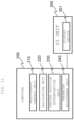
- FIG. 11 is a functional block diagram showing the computer 200 to which the above-described function is added.
- the imaging position determination unit 230 has the same configuration as shown in FIG. 3 .
- the parameter adjustment unit 240 is added in the computer 200.
- FIG. 12 there will now be described the processing performed by the imaging position determination unit 230 and the parameter adjustment unit 240 of the present embodiment, focusing on the point different from the first embodiment.
- the following steps are the same as those in the first embodiment, i.e., the scout image is taken (S61), the Scanning region on the scout image is calculated, and the imaging position is decided with adjustment as needed (S62).
- the imaging parameter determined by the decided imaging range is reflected on the parameter of the task for actually taking the examination image (S63).
- parameters 60 related to the imaging range are values manually set by the user or values automatically calculated by the system.
- the parameter adjustment unit 240 executes the parameter consistency check (S65).
- S65 consistency check
- any of the parameters 60 related to the Scanning region has changed from the default value, it is checked whether there is any other parameter that needs to be changed in conjunction therewith, and a process is performed to calculate a value to be set for the parameter to be changed.
- Checking whether there is any other parameter to be changed among the parameters 60, in conjunction with the change from the default value is performed using the information set in the system such as a reference table. For example, when the FOV of the parameters 60 is changed to a value larger than the default value (S66), the imaging will not be disabled with the larger FOV. That is, there are no other parameters needed to be changed. Thus, this value of the parameters 60 is only changed (S67). On the other hand, when the FOV is changed to a value smaller than the default value, this value of the parameters 60 is kept as the default value.
- the slice number in the calculated parameters 60 is larger than the default value (S68)
- the number of imaging slices increases, and thus imaging time is extended though the imaging itself is possible.
- FIG. 14 is a flowchart showing the processing of automatic calculation by the parameter adjustment unit 240 according to the four options described above.
- the present embodiment in addition to the same effects as those of the first embodiment, it is possible to automatically calculate the parameter in conjunction with the change of the imaging range, and thus it is possible to obtain an effect of reducing the time and trouble of the user.
- the operator dependency of the parameter setting is reduced, and this can reduce a setting error that leads to a failure of the examination.
- the user since multiple options are presented to the user in an easy-to-understand expression together with the automatic calculation result, the user is allowed to select a desired description of change, thereby enabling parameter setting in accordance with the selected description of change.
Landscapes
- Physics & Mathematics (AREA)
- Health & Medical Sciences (AREA)
- Engineering & Computer Science (AREA)
- High Energy & Nuclear Physics (AREA)
- Condensed Matter Physics & Semiconductors (AREA)
- General Physics & Mathematics (AREA)
- Life Sciences & Earth Sciences (AREA)
- Signal Processing (AREA)
- Nuclear Medicine, Radiotherapy & Molecular Imaging (AREA)
- Biophysics (AREA)
- General Health & Medical Sciences (AREA)
- Radiology & Medical Imaging (AREA)
- Physiology (AREA)
- Cardiology (AREA)
- Power Engineering (AREA)
- Pulmonology (AREA)
- Pathology (AREA)
- Biomedical Technology (AREA)
- Heart & Thoracic Surgery (AREA)
- Medical Informatics (AREA)
- Molecular Biology (AREA)
- Surgery (AREA)
- Animal Behavior & Ethology (AREA)
- Public Health (AREA)
- Veterinary Medicine (AREA)
- Magnetic Resonance Imaging Apparatus (AREA)
Claims (12)
- Magnetresonanztomographie-Vorrichtung, die zum automatischen Einstellen einer Bildgebungsposition konfiguriert ist, umfassendeine Bildgebungseinheit (100), die so konfiguriert ist, dass sie ein Bild einer Untersuchungsperson (101) auf der Grundlage von Kernspintomographie erfasst, und eine Bildgebungspositions-Bestimmungseinheit (230), die so konfiguriert ist, dass sie einen Bildgebungsbereich (902, 903) der Untersuchungsperson (101) berechnet und eine Bildgebungsposition der Untersuchungsperson (101) für eine schichtbasierte Hauptabtastung bei Magnetresonanztomographie bestimmt,und eine Messsteuerungseinheit (210), die so konfiguriert ist, dass sie die Bildgebungseinheit (100) steuert, um einen Scout-Scan, der Erfassung von mehreren Einzelbildern enthält, während eines oder mehrerer Zyklen einer periodischen Atembewegung der Untersuchungsperson (101) durchzuführen, wobei die Bildgebungspositions-Bestimmungseinheit (230) so ausgelegt ist, dass sie die von der Bildgebungseinheit (100) erfassten Einzelbilder verwendet, um mehrere Bildgebungsbereiche (902, 903) einschließlich eines minimalen Bildgebungsbereichs (902), der ein vorbestimmtes Gewebe zu einem Zeitpunkt des Atemanhaltens der Untersuchungsperson (101) umfasst, und eines maximalen Bildgebungsbereichs (903), der einen Bereich, in dem das Gewebe innerhalb eines Zyklus der periodischen Atembewegung zu einem Zeitpunkt von freiem Atmen der Untersuchungsperson (101) verschoben wird, umfasst, zu berechnen, undeinen der mehreren Bildgebungsbereiche (902, 903) als die Bildgebungsposition für die Hauptabtastung gemäß Bildgebungsbedingungen bestimmt, wobei die Bildgebungsbedingungen eine Bildgebung mit angehaltenem Atem, während der die Bildgebungspositions-Bestimmungseinheit (230) die Bildgebungsposition an einer Position in Übereinstimmung mit einer Phase der periodischen Atembewegung bestimmt und den minimalen Bildgebungsbereich (902) als den Bildgebungsbereich einstellt, enthalten, unddie Bildgebungsbedingungen eine atemgetriggerte Bildgebung, während der die Bildgebungspositions-Bestimmungseinheit (230) die Bildgebungsposition durch Einstellen des maximalen Bildgebungsbereichs (903) als des Bildgebungsbereichs bestimmt, enthalten.
- Magnetresonanztomographie-Vorrichtung nach Anspruch 1,
wobei die Bildgebungspositions-Bestimmungseinheit (230) eine Gewebeextraktionseinheit (233) umfasst, die so konfiguriert ist, dass sie eine Position und einen Bereich eines Zielorgans unter Verwendung der durch den Scout-Scan erfassten Einzelbilder detektiert. - Magnetresonanztomographie-Vorrichtung nach Anspruch 1 oder 2,
wobei die Bildgebungspositions-Bestimmungseinheit (230) eine Phase der periodischen Atembewegung der Untersuchungsperson (101) aus den durch den Scout-Scan erfassten Einzelbildern berechnet. - Magnetresonanztomographie-Vorrichtung nach einem der vorhergehenden Ansprüche, wobei die Magnetresonanztomographie-Vorrichtung ferner eine UI-Einheit (300) umfasst, die so konfiguriert ist, dass sie eine GUI anzeigt, die dazu auffordert, entweder Bildgebung mit angehaltenem Atem oder atemgetriggerte Bildgebung als eine der Bildgebungsbedingungen auszuwählen.
- Magnetresonanztomographie-Vorrichtung nach einem der vorhergehenden Ansprüche, wobei die Bildgebungspositions-Bestimmungseinheit (230) ferner eine Navigatorpositions-Bestimmungseinheit (239) umfasst, die so konfiguriert ist, dass sie eine Anwendungsposition eines Navigatorechos, das bei der atemgetriggerten Bildgebung verwendet wird, bestimmt.
- Magnetresonanztomographie-Vorrichtung nach einem der vorhergehenden Ansprüche, ferner umfassend
eine Parameteranpassungseinheit (240), die so konfiguriert ist, dass sie einen beliebigen Wert von Bildgebungsparametern in Übereinstimmung mit einem Bildgebungsbereich (902, 903), der von der Bildgebungspositions-Bestimmungseinheit (230) berechnet wurde, anpasst. - Magnetresonanztomographie-Vorrichtung nach Anspruch 6,
wobei die Parameteranpassungseinheit (240) die Bildgebungsparameter, die durch einen jeweiligen Bildgebungsbereich (902, 903) bestimmt werden, mit voreingestellten Bildgebungsparametern vergleicht und bestimmt, ob einer der Bildgebungsparameter geändert werden muss oder nicht. - Magnetresonanztomographie-Vorrichtung nach Anspruch 6 oder 7,
wobei die Bildgebungsparameter eine Schichtdicke, eine Schichtnummer und ein Sichtfeld (FOV) enthalten. - Magnetresonanztomographie-Vorrichtung nach einem der Ansprüche 6 bis 8,
wobei die Parameteranpassungseinheit (240) die Werte der Bildgebungsparameter in mehreren Mustern gemäß einer Priorität der Bildgebungsbedingungen berechnet. - Magnetresonanztomographie-Vorrichtung nach Anspruch 9,
wobei die Parameteranpassungseinheit (240) eine GUI anzeigt, die einen Benutzer auffordert, die Priorität der Bildgebungsbedingungen auszuwählen. - Verfahren des automatischen Bestimmens einer Bildgebungsposition einer Untersuchungsperson (101) für eine schichtbasierte Hauptabtastung bei Magnetresonanztomographie, umfassend Berechnen mit mehreren Einzelbildern, die durch Durchführen eines Scout-Scans während eines oder mehrerer Zyklen einer periodischen Atembewegung der Untersuchungsperson (101) erfasst wurden, von mehreren Bildgebungsbereichen (902, 903) einschließlich eines minimalen Bildgebungsbereichs (902), der ein vorbestimmtes Gewebe zu einem Zeitpunkt des Atemanhaltens der Untersuchungsperson (101) umfasst, und eines maximalen Bildgebungsbereichs (903), der einen Bereich, in dem das Gewebe innerhalb eines Zyklus einer periodischen Atembewegung zu einem Zeitpunkt von freiem Atmen der Untersuchungsperson (101) verschoben wird, umfasst, undBestimmen einer der mehreren Bildgebungsbereiche (902, 903) als die Bildgebungsposition für die Hauptabtastung gemäß Bildgebungsbedingungen, wobei die Bildgebungsbedingungen eine Bildgebung mit angehaltenem Atem, während der die Bildgebungsposition an einer Position in Übereinstimmung mit einer Phase der periodischen Atembewegung bestimmt wird, und der minimale Bildgebungsbereich (902) als der Bildgebungsbereich eingestellt wird, enthalten, unddie Bildgebungsbedingungen eine atemgetriggerte Bildgebung, während der die Bildgebungsposition durch Einstellen des maximalen Bildgebungsbereichs (903) als des Bildgebungsbereichs bestimmt wird, enthalten.
- Verfahren des Bestimmens der Bildgebungsposition nach Anspruch 11,
wobei nach Berechnen der Bildgebungsbereiche (902, 903) bestimmt wird, ob Bildgebungsparameter geändert werden müssen oder nicht, und wenn die Änderung erforderlich ist, ein Wert eines jeweiligen Bildgebungsparameters, der zu ändern ist, berechnet wird.
Applications Claiming Priority (1)
| Application Number | Priority Date | Filing Date | Title |
|---|---|---|---|
| JP2022085517A JP7824821B2 (ja) | 2022-05-25 | 2022-05-25 | 磁気共鳴イメージング装置、及び、撮像位置決定方法 |
Publications (2)
| Publication Number | Publication Date |
|---|---|
| EP4283322A1 EP4283322A1 (de) | 2023-11-29 |
| EP4283322B1 true EP4283322B1 (de) | 2025-06-25 |
Family
ID=86497937
Family Applications (1)
| Application Number | Title | Priority Date | Filing Date |
|---|---|---|---|
| EP23174467.3A Active EP4283322B1 (de) | 2022-05-25 | 2023-05-22 | Magnetresonanzbildgebungsvorrichtung und bildgebungspositionsbestimmungsverfahren |
Country Status (4)
| Country | Link |
|---|---|
| US (1) | US12345790B2 (de) |
| EP (1) | EP4283322B1 (de) |
| JP (1) | JP7824821B2 (de) |
| CN (1) | CN117129922A (de) |
Family Cites Families (17)
| Publication number | Priority date | Publication date | Assignee | Title |
|---|---|---|---|---|
| JP4250251B2 (ja) | 1999-04-13 | 2009-04-08 | 株式会社日立メディコ | 磁気共鳴画像診断装置 |
| JP5465565B2 (ja) | 2010-03-25 | 2014-04-09 | 株式会社日立メディコ | 磁気共鳴イメージング装置 |
| JP5660807B2 (ja) | 2010-05-31 | 2015-01-28 | ジーイー・メディカル・システムズ・グローバル・テクノロジー・カンパニー・エルエルシー | 磁気共鳴イメージング装置、スライス位置設定方法、およびプログラム |
| WO2012095797A2 (en) * | 2011-01-14 | 2012-07-19 | Koninklijke Philips Electronics N.V. | 4d contrast enhanced computed tomography (ct) |
| WO2012137563A1 (ja) | 2011-04-01 | 2012-10-11 | 株式会社日立メディコ | 磁気共鳴イメージング装置および磁気共鳴イメージング方法 |
| JP5944650B2 (ja) | 2011-11-11 | 2016-07-05 | 東芝メディカルシステムズ株式会社 | 磁気共鳴イメージング装置 |
| US9251560B2 (en) | 2011-12-21 | 2016-02-02 | Hitachi Medical Corporation | Medical image diagnosis apparatus and phase determination method using medical image diagnosis apparatus |
| JP6174908B2 (ja) | 2013-05-27 | 2017-08-02 | キヤノン株式会社 | 情報処理装置、情報処理方法、及び、コンピュータプログラム |
| JP2016049277A (ja) | 2014-08-29 | 2016-04-11 | ジーイー・メディカル・システムズ・グローバル・テクノロジー・カンパニー・エルエルシー | 磁気共鳴イメージング装置 |
| JP6461680B2 (ja) | 2015-03-31 | 2019-01-30 | ジーイー・メディカル・システムズ・グローバル・テクノロジー・カンパニー・エルエルシー | 磁気共鳴装置およびプログラム |
| JP6554723B2 (ja) | 2015-06-30 | 2019-08-07 | ジーイー・メディカル・システムズ・グローバル・テクノロジー・カンパニー・エルエルシー | 磁気共鳴装置およびプログラム |
| EP3384842B1 (de) | 2017-04-07 | 2024-11-06 | Siemens Healthineers AG | Erkennung der position und frequenz eines sich periodisch bewegenden organs in einer mrt-untersuchung |
| CN109717869B (zh) | 2017-10-31 | 2024-05-14 | 通用电气公司 | 磁共振成像过程中的运动监测方法、计算机程序、存储设备 |
| JP7211725B2 (ja) | 2018-07-09 | 2023-01-24 | 富士フイルムヘルスケア株式会社 | 自動位置決め機能付き磁気共鳴イメージング装置、磁気共鳴イメージング装置の制御方法、及び、撮像断面自動設定用プログラム |
| JP7237608B2 (ja) | 2019-01-28 | 2023-03-13 | キヤノンメディカルシステムズ株式会社 | 患者アナウンス装置、放射線治療装置及び患者アナウンス方法 |
| US11633623B2 (en) | 2019-04-19 | 2023-04-25 | University Of Maryland, Baltimore | System and method for radiation therapy using spatial-functional mapping and dose sensitivity of branching structures and functional sub-volumes |
| CN110755075B (zh) | 2019-10-30 | 2023-07-25 | 上海联影医疗科技股份有限公司 | 磁共振成像方法、装置、设备和存储介质 |
-
2022
- 2022-05-25 JP JP2022085517A patent/JP7824821B2/ja active Active
-
2023
- 2023-03-15 CN CN202310251479.5A patent/CN117129922A/zh active Pending
- 2023-05-16 US US18/197,812 patent/US12345790B2/en active Active
- 2023-05-22 EP EP23174467.3A patent/EP4283322B1/de active Active
Also Published As
| Publication number | Publication date |
|---|---|
| EP4283322A1 (de) | 2023-11-29 |
| JP2023173337A (ja) | 2023-12-07 |
| US12345790B2 (en) | 2025-07-01 |
| JP7824821B2 (ja) | 2026-03-05 |
| US20230384408A1 (en) | 2023-11-30 |
| CN117129922A (zh) | 2023-11-28 |
Similar Documents
| Publication | Publication Date | Title |
|---|---|---|
| US8928318B2 (en) | MRI apparatus and method for generating automatically positioned 2D slice images of heart tissue from acquired 3D heart image data | |
| US8502532B2 (en) | Magnetic resonance data acquisition system and method with recursively adapted object-specific measurement parameter adjustment during patient movement through the MRI system | |
| CN101427284B (zh) | 用于没有计时约束的动态体积对准的运动校正方法 | |
| KR101659142B1 (ko) | 영상 데이터를 생성하는 방법 | |
| US10203385B2 (en) | Magnetic resonance imaging apparatus and magnetic resonance imaging method | |
| JP5944650B2 (ja) | 磁気共鳴イメージング装置 | |
| EP2505162A1 (de) | Verfahren und Vorrichtung zum Erzeugen eines medizinischen Bildes eines Körperorgans unter Verwendung eines 3-D-Modells | |
| JP5591545B2 (ja) | 磁気共鳴映像装置 | |
| JP2007029250A (ja) | 磁気共鳴イメージング装置 | |
| CN112568891A (zh) | 自动定位患者的待检查区域以用于医学成像检查的方法及设计用于执行方法的医学成像设备 | |
| JP6462286B2 (ja) | 磁気共鳴イメージング装置 | |
| JPH05269113A (ja) | Mriにおける位置決め撮影方法 | |
| JP3993799B2 (ja) | 磁気共鳴イメージング装置 | |
| JPWO2004080301A1 (ja) | 磁気共鳴イメージング装置 | |
| WO2002082994A1 (en) | Magnetic resonance imaging apparatus and image processing method | |
| JP4558397B2 (ja) | 磁気共鳴イメージング装置 | |
| EP4283322A1 (de) | Magnetresonanzbildgebungsvorrichtung und bildgebungspositionsbestimmungsverfahren | |
| JP7529438B2 (ja) | 磁気共鳴イメージング装置及びその制御プログラム | |
| JP2008206959A (ja) | 磁気共鳴イメージング装置およびスライス領域設定方法 | |
| JP6611426B2 (ja) | 磁気共鳴イメージング装置及び医用画像処理方法 | |
| JP7668115B2 (ja) | 磁気共鳴イメージング装置およびプログラム | |
| JP4282152B2 (ja) | Mri装置 | |
| US12631706B2 (en) | Preparing a magnetic resonance imaging method | |
| US20240288522A1 (en) | Preparing a Magnetic Resonance Imaging Method | |
| CN118749943B (zh) | 磁共振摄像装置及其控制方法 |
Legal Events
| Date | Code | Title | Description |
|---|---|---|---|
| PUAI | Public reference made under article 153(3) epc to a published international application that has entered the european phase |
Free format text: ORIGINAL CODE: 0009012 |
|
| STAA | Information on the status of an ep patent application or granted ep patent |
Free format text: STATUS: REQUEST FOR EXAMINATION WAS MADE |
|
| 17P | Request for examination filed |
Effective date: 20230522 |
|
| AK | Designated contracting states |
Kind code of ref document: A1 Designated state(s): AL AT BE BG CH CY CZ DE DK EE ES FI FR GB GR HR HU IE IS IT LI LT LU LV MC ME MK MT NL NO PL PT RO RS SE SI SK SM TR |
|
| RAP1 | Party data changed (applicant data changed or rights of an application transferred) |
Owner name: FUJIFILM CORPORATION |
|
| GRAP | Despatch of communication of intention to grant a patent |
Free format text: ORIGINAL CODE: EPIDOSNIGR1 |
|
| STAA | Information on the status of an ep patent application or granted ep patent |
Free format text: STATUS: GRANT OF PATENT IS INTENDED |
|
| INTG | Intention to grant announced |
Effective date: 20250404 |
|
| RIN1 | Information on inventor provided before grant (corrected) |
Inventor name: GOTO, TOMOHIRO Inventor name: IKEGAWA, AYAKA |
|
| GRAS | Grant fee paid |
Free format text: ORIGINAL CODE: EPIDOSNIGR3 |
|
| GRAA | (expected) grant |
Free format text: ORIGINAL CODE: 0009210 |
|
| STAA | Information on the status of an ep patent application or granted ep patent |
Free format text: STATUS: THE PATENT HAS BEEN GRANTED |
|
| AK | Designated contracting states |
Kind code of ref document: B1 Designated state(s): AL AT BE BG CH CY CZ DE DK EE ES FI FR GB GR HR HU IE IS IT LI LT LU LV MC ME MK MT NL NO PL PT RO RS SE SI SK SM TR |
|
| P01 | Opt-out of the competence of the unified patent court (upc) registered |
Free format text: CASE NUMBER: APP_23145/2025 Effective date: 20250515 |
|
| REG | Reference to a national code |
Ref country code: GB Ref legal event code: FG4D |
|
| REG | Reference to a national code |
Ref country code: CH Ref legal event code: EP |
|
| REG | Reference to a national code |
Ref country code: CH Ref legal event code: EP |
|
| REG | Reference to a national code |
Ref country code: IE Ref legal event code: FG4D |
|
| REG | Reference to a national code |
Ref country code: DE Ref legal event code: R096 Ref document number: 602023004220 Country of ref document: DE |
|
| PG25 | Lapsed in a contracting state [announced via postgrant information from national office to epo] |
Ref country code: FI Free format text: LAPSE BECAUSE OF FAILURE TO SUBMIT A TRANSLATION OF THE DESCRIPTION OR TO PAY THE FEE WITHIN THE PRESCRIBED TIME-LIMIT Effective date: 20250625 |
|
| REG | Reference to a national code |
Ref country code: LT Ref legal event code: MG9D |
|
| PG25 | Lapsed in a contracting state [announced via postgrant information from national office to epo] |
Ref country code: NO Free format text: LAPSE BECAUSE OF FAILURE TO SUBMIT A TRANSLATION OF THE DESCRIPTION OR TO PAY THE FEE WITHIN THE PRESCRIBED TIME-LIMIT Effective date: 20250925 Ref country code: GR Free format text: LAPSE BECAUSE OF FAILURE TO SUBMIT A TRANSLATION OF THE DESCRIPTION OR TO PAY THE FEE WITHIN THE PRESCRIBED TIME-LIMIT Effective date: 20250926 |
|
| PG25 | Lapsed in a contracting state [announced via postgrant information from national office to epo] |
Ref country code: BG Free format text: LAPSE BECAUSE OF FAILURE TO SUBMIT A TRANSLATION OF THE DESCRIPTION OR TO PAY THE FEE WITHIN THE PRESCRIBED TIME-LIMIT Effective date: 20250625 |
|
| PG25 | Lapsed in a contracting state [announced via postgrant information from national office to epo] |
Ref country code: HR Free format text: LAPSE BECAUSE OF FAILURE TO SUBMIT A TRANSLATION OF THE DESCRIPTION OR TO PAY THE FEE WITHIN THE PRESCRIBED TIME-LIMIT Effective date: 20250625 |
|
| PG25 | Lapsed in a contracting state [announced via postgrant information from national office to epo] |
Ref country code: RS Free format text: LAPSE BECAUSE OF FAILURE TO SUBMIT A TRANSLATION OF THE DESCRIPTION OR TO PAY THE FEE WITHIN THE PRESCRIBED TIME-LIMIT Effective date: 20250925 |
|
| PG25 | Lapsed in a contracting state [announced via postgrant information from national office to epo] |
Ref country code: LV Free format text: LAPSE BECAUSE OF FAILURE TO SUBMIT A TRANSLATION OF THE DESCRIPTION OR TO PAY THE FEE WITHIN THE PRESCRIBED TIME-LIMIT Effective date: 20250625 |
|
| REG | Reference to a national code |
Ref country code: NL Ref legal event code: MP Effective date: 20250625 |
|
| PG25 | Lapsed in a contracting state [announced via postgrant information from national office to epo] |
Ref country code: NL Free format text: LAPSE BECAUSE OF FAILURE TO SUBMIT A TRANSLATION OF THE DESCRIPTION OR TO PAY THE FEE WITHIN THE PRESCRIBED TIME-LIMIT Effective date: 20250625 |
|
| PG25 | Lapsed in a contracting state [announced via postgrant information from national office to epo] |
Ref country code: PT Free format text: LAPSE BECAUSE OF FAILURE TO SUBMIT A TRANSLATION OF THE DESCRIPTION OR TO PAY THE FEE WITHIN THE PRESCRIBED TIME-LIMIT Effective date: 20251027 |
|
| REG | Reference to a national code |
Ref country code: AT Ref legal event code: MK05 Ref document number: 1806985 Country of ref document: AT Kind code of ref document: T Effective date: 20250625 |
|
| PG25 | Lapsed in a contracting state [announced via postgrant information from national office to epo] |
Ref country code: IS Free format text: LAPSE BECAUSE OF FAILURE TO SUBMIT A TRANSLATION OF THE DESCRIPTION OR TO PAY THE FEE WITHIN THE PRESCRIBED TIME-LIMIT Effective date: 20251025 |
|
| PG25 | Lapsed in a contracting state [announced via postgrant information from national office to epo] |
Ref country code: AT Free format text: LAPSE BECAUSE OF FAILURE TO SUBMIT A TRANSLATION OF THE DESCRIPTION OR TO PAY THE FEE WITHIN THE PRESCRIBED TIME-LIMIT Effective date: 20250625 Ref country code: SM Free format text: LAPSE BECAUSE OF FAILURE TO SUBMIT A TRANSLATION OF THE DESCRIPTION OR TO PAY THE FEE WITHIN THE PRESCRIBED TIME-LIMIT Effective date: 20250625 |
|
| PG25 | Lapsed in a contracting state [announced via postgrant information from national office to epo] |
Ref country code: CZ Free format text: LAPSE BECAUSE OF FAILURE TO SUBMIT A TRANSLATION OF THE DESCRIPTION OR TO PAY THE FEE WITHIN THE PRESCRIBED TIME-LIMIT Effective date: 20250625 |
|
| PG25 | Lapsed in a contracting state [announced via postgrant information from national office to epo] |
Ref country code: PL Free format text: LAPSE BECAUSE OF FAILURE TO SUBMIT A TRANSLATION OF THE DESCRIPTION OR TO PAY THE FEE WITHIN THE PRESCRIBED TIME-LIMIT Effective date: 20250625 |
|
| PG25 | Lapsed in a contracting state [announced via postgrant information from national office to epo] |
Ref country code: EE Free format text: LAPSE BECAUSE OF FAILURE TO SUBMIT A TRANSLATION OF THE DESCRIPTION OR TO PAY THE FEE WITHIN THE PRESCRIBED TIME-LIMIT Effective date: 20250625 |
|
| PG25 | Lapsed in a contracting state [announced via postgrant information from national office to epo] |
Ref country code: SK Free format text: LAPSE BECAUSE OF FAILURE TO SUBMIT A TRANSLATION OF THE DESCRIPTION OR TO PAY THE FEE WITHIN THE PRESCRIBED TIME-LIMIT Effective date: 20250625 |
|
| PG25 | Lapsed in a contracting state [announced via postgrant information from national office to epo] |
Ref country code: ES Free format text: LAPSE BECAUSE OF FAILURE TO SUBMIT A TRANSLATION OF THE DESCRIPTION OR TO PAY THE FEE WITHIN THE PRESCRIBED TIME-LIMIT Effective date: 20250625 |
|
| PG25 | Lapsed in a contracting state [announced via postgrant information from national office to epo] |
Ref country code: DK Free format text: LAPSE BECAUSE OF FAILURE TO SUBMIT A TRANSLATION OF THE DESCRIPTION OR TO PAY THE FEE WITHIN THE PRESCRIBED TIME-LIMIT Effective date: 20250625 |
|
| PG25 | Lapsed in a contracting state [announced via postgrant information from national office to epo] |
Ref country code: IT Free format text: LAPSE BECAUSE OF FAILURE TO SUBMIT A TRANSLATION OF THE DESCRIPTION OR TO PAY THE FEE WITHIN THE PRESCRIBED TIME-LIMIT Effective date: 20250625 |
|
| PLBE | No opposition filed within time limit |
Free format text: ORIGINAL CODE: 0009261 |
|
| STAA | Information on the status of an ep patent application or granted ep patent |
Free format text: STATUS: NO OPPOSITION FILED WITHIN TIME LIMIT |
|
| REG | Reference to a national code |
Ref country code: CH Ref legal event code: L10 Free format text: ST27 STATUS EVENT CODE: U-0-0-L10-L00 (AS PROVIDED BY THE NATIONAL OFFICE) Effective date: 20260507 |