EP4282546B1 - Hochdruckreinigungsgerät - Google Patents
Hochdruckreinigungsgerät Download PDFInfo
- Publication number
- EP4282546B1 EP4282546B1 EP22175191.0A EP22175191A EP4282546B1 EP 4282546 B1 EP4282546 B1 EP 4282546B1 EP 22175191 A EP22175191 A EP 22175191A EP 4282546 B1 EP4282546 B1 EP 4282546B1
- Authority
- EP
- European Patent Office
- Prior art keywords
- cleaning device
- pressure
- main line
- pressure cleaning
- operating element
- Prior art date
- Legal status (The legal status is an assumption and is not a legal conclusion. Google has not performed a legal analysis and makes no representation as to the accuracy of the status listed.)
- Active
Links
Images

Classifications
-
- B—PERFORMING OPERATIONS; TRANSPORTING
- B08—CLEANING
- B08B—CLEANING IN GENERAL; PREVENTION OF FOULING IN GENERAL
- B08B3/00—Cleaning by methods involving the use or presence of liquid or steam
- B08B3/02—Cleaning by the force of jets or sprays
- B08B3/026—Cleaning by making use of hand-held spray guns; Fluid preparations therefor
-
- B—PERFORMING OPERATIONS; TRANSPORTING
- B08—CLEANING
- B08B—CLEANING IN GENERAL; PREVENTION OF FOULING IN GENERAL
- B08B3/00—Cleaning by methods involving the use or presence of liquid or steam
- B08B3/02—Cleaning by the force of jets or sprays
- B08B3/026—Cleaning by making use of hand-held spray guns; Fluid preparations therefor
- B08B3/028—Spray guns
-
- B—PERFORMING OPERATIONS; TRANSPORTING
- B05—SPRAYING OR ATOMISING IN GENERAL; APPLYING FLUENT MATERIALS TO SURFACES, IN GENERAL
- B05B—SPRAYING APPARATUS; ATOMISING APPARATUS; NOZZLES
- B05B11/00—Single-unit hand-held apparatus in which flow of contents is produced by the muscular force of the operator at the moment of use
- B05B11/01—Single-unit hand-held apparatus in which flow of contents is produced by the muscular force of the operator at the moment of use characterised by the means producing the flow
- B05B11/10—Pump arrangements for transferring the contents from the container to a pump chamber by a sucking effect and forcing the contents out through the dispensing nozzle
- B05B11/1042—Components or details
-
- B—PERFORMING OPERATIONS; TRANSPORTING
- B05—SPRAYING OR ATOMISING IN GENERAL; APPLYING FLUENT MATERIALS TO SURFACES, IN GENERAL
- B05B—SPRAYING APPARATUS; ATOMISING APPARATUS; NOZZLES
- B05B11/00—Single-unit hand-held apparatus in which flow of contents is produced by the muscular force of the operator at the moment of use
- B05B11/0005—Components or details
- B05B11/0062—Outlet valves actuated by the pressure of the fluid to be sprayed
-
- B—PERFORMING OPERATIONS; TRANSPORTING
- B08—CLEANING
- B08B—CLEANING IN GENERAL; PREVENTION OF FOULING IN GENERAL
- B08B13/00—Accessories or details of general applicability for machines or apparatus for cleaning
-
- F—MECHANICAL ENGINEERING; LIGHTING; HEATING; WEAPONS; BLASTING
- F04—POSITIVE - DISPLACEMENT MACHINES FOR LIQUIDS; PUMPS FOR LIQUIDS OR ELASTIC FLUIDS
- F04B—POSITIVE-DISPLACEMENT MACHINES FOR LIQUIDS; PUMPS
- F04B49/00—Control, e.g. of pump delivery, or pump pressure of, or safety measures for, machines, pumps, or pumping installations, not otherwise provided for, or of interest apart from, groups F04B1/00 - F04B47/00
- F04B49/02—Stopping, starting, unloading or idling control
- F04B49/03—Stopping, starting, unloading or idling control by means of valves
- F04B49/035—Bypassing
-
- F—MECHANICAL ENGINEERING; LIGHTING; HEATING; WEAPONS; BLASTING
- F04—POSITIVE - DISPLACEMENT MACHINES FOR LIQUIDS; PUMPS FOR LIQUIDS OR ELASTIC FLUIDS
- F04B—POSITIVE-DISPLACEMENT MACHINES FOR LIQUIDS; PUMPS
- F04B49/00—Control, e.g. of pump delivery, or pump pressure of, or safety measures for, machines, pumps, or pumping installations, not otherwise provided for, or of interest apart from, groups F04B1/00 - F04B47/00
- F04B49/22—Control, e.g. of pump delivery, or pump pressure of, or safety measures for, machines, pumps, or pumping installations, not otherwise provided for, or of interest apart from, groups F04B1/00 - F04B47/00 by means of valves
- F04B49/24—Bypassing
-
- B—PERFORMING OPERATIONS; TRANSPORTING
- B05—SPRAYING OR ATOMISING IN GENERAL; APPLYING FLUENT MATERIALS TO SURFACES, IN GENERAL
- B05B—SPRAYING APPARATUS; ATOMISING APPARATUS; NOZZLES
- B05B12/00—Arrangements for controlling delivery; Arrangements for controlling the spray area
-
- B—PERFORMING OPERATIONS; TRANSPORTING
- B05—SPRAYING OR ATOMISING IN GENERAL; APPLYING FLUENT MATERIALS TO SURFACES, IN GENERAL
- B05B—SPRAYING APPARATUS; ATOMISING APPARATUS; NOZZLES
- B05B9/00—Spraying apparatus for discharge of liquids or other fluent material, without essentially mixing with gas or vapour
- B05B9/03—Spraying apparatus for discharge of liquids or other fluent material, without essentially mixing with gas or vapour characterised by means for supplying liquid or other fluent material
- B05B9/04—Spraying apparatus for discharge of liquids or other fluent material, without essentially mixing with gas or vapour characterised by means for supplying liquid or other fluent material with pressurised or compressible container; with pump
- B05B9/0403—Spraying apparatus for discharge of liquids or other fluent material, without essentially mixing with gas or vapour characterised by means for supplying liquid or other fluent material with pressurised or compressible container; with pump with pumps for liquids or other fluent material
-
- B—PERFORMING OPERATIONS; TRANSPORTING
- B08—CLEANING
- B08B—CLEANING IN GENERAL; PREVENTION OF FOULING IN GENERAL
- B08B2203/00—Details of cleaning machines or methods involving the use or presence of liquid or steam
- B08B2203/02—Details of machines or methods for cleaning by the force of jets or sprays
- B08B2203/0205—Bypass pressure relief valves
-
- B—PERFORMING OPERATIONS; TRANSPORTING
- B08—CLEANING
- B08B—CLEANING IN GENERAL; PREVENTION OF FOULING IN GENERAL
- B08B2203/00—Details of cleaning machines or methods involving the use or presence of liquid or steam
- B08B2203/02—Details of machines or methods for cleaning by the force of jets or sprays
- B08B2203/0223—Electric motor pumps
-
- B—PERFORMING OPERATIONS; TRANSPORTING
- B08—CLEANING
- B08B—CLEANING IN GENERAL; PREVENTION OF FOULING IN GENERAL
- B08B2203/00—Details of cleaning machines or methods involving the use or presence of liquid or steam
- B08B2203/02—Details of machines or methods for cleaning by the force of jets or sprays
- B08B2203/0229—Suction chambers for aspirating the sprayed liquid
-
- B—PERFORMING OPERATIONS; TRANSPORTING
- B08—CLEANING
- B08B—CLEANING IN GENERAL; PREVENTION OF FOULING IN GENERAL
- B08B2203/00—Details of cleaning machines or methods involving the use or presence of liquid or steam
- B08B2203/02—Details of machines or methods for cleaning by the force of jets or sprays
- B08B2203/027—Pump details
Definitions
- the invention relates to a high-pressure cleaning device according to the preamble of claim 1.
- a high-pressure cleaning device in which the pressure in the pressure chamber of the high-pressure cleaning device can be adjusted in stages.
- an input unit is arranged on the gun of the high-pressure cleaning device.
- the input unit for the step-by-step adjustment of the pressure is designed separately from an operating lever, which is used to open a valve in the main line of the high-pressure cleaning device. Water can only be sprayed from the gun of the high-pressure cleaning device if this main line valve is opened using the operating lever. A pressure level is selected using the input unit and the main line valve is then opened using the operating lever.
- Adjusting the pressure level while liquid is being sprayed is only possible in an uncomfortable way; while spraying, the operating lever is pressed with a finger, and either the other hand or the thumb must be used to adjust the pressure. Operating the high-pressure cleaning device with one hand is then difficult.
- the DE 2004 031 951 B3 discloses a high-pressure cleaning device with a bypass line in which a spring-loaded overflow valve is arranged.
- the invention is based on the object of developing a generic high-pressure cleaning device in such a way that a comfortable adjustment of the pressure is possible.
- the high-pressure cleaning device is designed in such a way that the operation of the main line valve to switch the main line valve between the open state and the closed state and the operation of the bypass valve to adjust the bypass valve can be triggered by operating the operating element using a continuous movement of a single finger, in particular one after the other.
- the high-pressure cleaning device comprises a detector which is designed to detect an adjustment position of the operating element.
- the detector is designed to detect several different adjustment positions.
- the operating element can be continuously adjusted to different adjustment positions within a range.
- the detector is expediently designed to detect any adjustment position within this continuous range.
- the detector is preferably a potentiometer.
- the detector is a Hall sensor. This enables precise detection of the adjustment position of the control element, particularly within a range in which the control element can be continuously adjusted.
- the high-pressure cleaning device is designed in such a way that the bypass valve adjusts the size of the free cross-sectional area depending on the adjustment position of the control element.
- the size of the free cross-sectional area can be continuously adjusted using the control element.
- the combination of the continuous adjustability of the control element with the dual function of the control element with regard to switching the main line valve and adjusting the bypass valve results in a dynamic operating behavior of the high-pressure cleaning device.
- the user of the high-pressure cleaning device can briefly increase the pressure in an extremely convenient way by setting the control element, which he has to operate anyway so that the main line valve is opened and water is sprayed out, to a other adjustment position. Adjusting the control element to another adjustment position can be done in particular by pressing the control element using a finger of the user.
- the bypass valve is conveniently adjustable using a servomotor. This allows the free cross-sectional area of the bypass line to be adjusted in a convenient manner.
- the bypass valve is adjustable using a signal triggered by the control element.
- the signal is preferably transmitted wirelessly. This minimizes the risk of a cable break. However, it can also be provided that the signal is transmitted using a cable.
- the high-pressure cleaning device conveniently includes a motor to drive the high-pressure pump.
- the motor is an induction motor.
- the motor is a brushless DC motor.
- the combination of pressure regulation via the bypass valve with an induction motor or a brushless DC motor enables the cost-effective use of these types of motor. Due to the bypass valve, no speed control is required for pressure regulation for these types of motor. This can save considerable costs. This also enables cost-effective production of a high-pressure cleaning device intended for a higher performance class.
- the high-pressure cleaning device is designed in such a way that the bypass valve is set when the control element is not operated so that the free cross-sectional area of the bypass line is at a maximum. This allows the maximum possible pressure equalization between the pressure chamber and the suction chamber when the control element is not operated. This minimizes the pressure applied to the main line valve.
- the high-pressure cleaning device is expediently designed in such a way that when the free cross-sectional area is at a maximum, before the free cross-sectional area of the bypass line is reduced by the control element, the main line valve can be switched from the closed to the open position by means of the control element. open state. This ensures that the main line valve is opened before the pressure in the pressure chamber of the main line increases. This prevents a high pressure being applied to the main line valve.
- the main line valve can therefore be designed for much lower pressures. This can save costs.
- the high-pressure cleaning device is designed in such a way that the free cross-sectional area of the bypass line is increased by means of the control element before the main line valve is moved from the (partially) open state to the (fully) closed state.
- the high-pressure cleaning device can be designed in such a way that the pressure in the pressure chamber is reduced before the main line valve is closed.
- the main line valve is designed to withstand a lower load when it is closed.
- the control element can be adjusted from the unactuated state from a rest position along an adjustment path into adjustment positions with increasing distance from the rest position.
- the high-pressure cleaning device is expediently designed in such a way that the bypass valve reduces the free cross-sectional area of the bypass line as the distance of the control element from the rest position increases. This enables dynamic pressure adjustment during operation of the high-pressure cleaning device, in particular while liquid is being sprayed out through the spray opening. The user can continuously adjust the pressure simply by operating the control element. At the same time, he can keep the main line valve open simply by operating the control element. This combination enables intuitive operation of the high-pressure cleaning device.
- the user can extremely conveniently increase the pressure for a short time by operating the control element more strongly and then reduce it again in another place where a lower pressure of the cleaning liquid is required by reducing the distance of the control element from its rest position.
- the high-pressure cleaning device is designed in such a way that the control element enables continuous adjustment of the pressure in the pressure chamber while liquid is being sprayed out of the spray opening.
- control element is a single component in which the functions of both the operation of the main line valve and the operation of the bypass valve are combined.
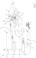
- Fig. 1 shows a high-pressure cleaning device 1.
- the high-pressure cleaning device 1 comprises a pump unit 18 and an ejection unit 11.
- the pump unit 18 and the ejection unit 11 are fluidically connected to one another via a main line 5.
- the ejection unit 11 consists of a gun.
- the ejection unit comprises a gun and a lance.
- the high-pressure cleaning device 1 comprises a connection 2 for a liquid source 17.
- the liquid source 17 is an external liquid source.
- the external liquid source is the faucet of a domestic water network. It can also be provided that the liquid source is an integral part of the high-pressure cleaning device.
- the high-pressure cleaning device 1 comprises an ejection opening 6.
- the high-pressure cleaning device 1 comprises the main line 5.
- the main line 5 of the high-pressure cleaning device 1 fluidically connects the connection 2 to the ejection opening 6.
- the connection 2 is arranged on the pump unit 18.
- the ejection opening 6 is arranged on the ejection unit 11.
- the ejection opening 6 is arranged on the ejection unit 6 designed as a pistol.
- the ejection opening is arranged on an exchangeable lance of the ejection unit.
- the high-pressure cleaning device 1 comprises a high-pressure pump 3.
- liquid can be conveyed through the main line 5 from the connection 2 to the injection opening 6.
- the liquid source 17 supplies liquid to the main line 5.
- the high-pressure pump 3 is arranged in the main line 5.
- the high-pressure pump 3 pressurizes the liquid.
- the high-pressure pump 3 is arranged between a suction chamber 9 and a pressure chamber 10 of the main line 5.
- the main line has the suction chamber 9 between the connection 2 and the high-pressure pump 3.
- the main line 5 has the pressure chamber 10 between the high-pressure pump 3 and the injection opening 6.
- the suction chamber 9 is formed by a section of the main line 5 between the connection 2 and the high-pressure pump 3.
- the pressure chamber 10 is formed by a section of the main line 5 between the high-pressure pump 3 and the injection opening 6.
- the high-pressure pump 3 conveys liquid from the suction chamber 9 to the pressure chamber 10. There is a higher pressure in the pressure chamber 10 than in the suction chamber 9.
- the suction chamber 9 and the pressure chamber 10 are part of the main line 5. Downstream of the high-pressure pump 3 there is a higher pressure in the main line 5 than upstream of the high-pressure pump 3.
- the high-pressure pump 3 is arranged in the pump unit 18.
- the high-pressure pump 3 is designed separately from the ejection unit 11.
- Various ejection units can be connected to the high-pressure pump 3.
- the high-pressure cleaning device 1 has a motor 4 to drive the high-pressure pump 3.
- the motor 4 is arranged in the pump unit 18.
- the motor 4 can be designed as a brushless direct current motor.
- a brushless direct current motor is also referred to as an EC motor.
- the motor can also be a universal motor.
- the motor 4 is an induction motor. In an induction motor, a rotating magnetic field of the stator sets the rotor in motion.
- the induction motor in the exemplary embodiment is operated with alternating current.
- the voltage source can be provided by the mains voltage, for example. If battery operation is provided, the motor can also be a brushless direct current motor. It can then be provided that the battery is part of the high-pressure cleaning device 1.
- the high-pressure cleaning device 1 comprises a main switch 19.
- the main switch 19 serves to interrupt the voltage supply of the entire high-pressure cleaning device 1.
- the main switch 19 is arranged on the pump unit 18.
- the high-pressure cleaning device 1 comprises a main line valve 8.
- the main line valve 8 is arranged in the main line 5.
- the main line valve 8 has two valve states.
- the two valve states include a closed state 20 ( Fig. 1 ) and an open state 40 ( Fig. 2 ).
- the open state 40 the main line valve 8 allows a flow of liquid through the main line.
- the closed state 20 the main line valve 8 prevents a flow of liquid through the main line 5.
- liquid is sprayed out of the ejection opening 6.
- no liquid is sprayed out of the ejection opening 6.
- the main line valve 8 is arranged in the ejection unit 11.
- the main line valve 8 is arranged between the high-pressure pump 3 and the ejection opening 6.
- the main line valve is arranged in the pump unit. It can It may also be provided that the main line valve is arranged between the connection and the high-pressure pump.
- the high-pressure cleaning device 1 has an operating element 7.
- the operating element 7 is designed separately from the main switch 19.
- the main line valve 8 can be switched between the open state 20 and the closed state 40 by means of the operating element 7.
- the operating element 7 is arranged on the ejection unit 11.
- the high-pressure cleaning device 1 has a bypass line 12.
- the pressure chamber 10 is fluidically connected to the suction chamber 9 via the bypass line 12.
- the bypass line 12 enables a further fluidic connection between the suction chamber 9 and the pressure chamber 10, separate from the fluidic connection between the suction chamber 9 and the pressure chamber 10 via the high-pressure pump 3.
- the pressure chamber 10 When the high-pressure pump 3 is in operation, the pressure chamber 10 has a higher pressure than the suction chamber 9. Due to this pressure gradient, liquid can flow from the pressure chamber 10 into the suction chamber 9 through the bypass line 12.
- a bypass valve 13 is arranged in the bypass line 12. The bypass valve 13 can be used to adjust the free cross-sectional area of the bypass line 12. This allows the pressure in the pressure chamber 10 to be regulated. With a larger free cross-sectional area, the pressure equalization between the pressure chamber 10 and the suction chamber 9 takes place to a greater extent. If there is to be a high pressure in the pressure chamber 10, the free cross-sectional area of the bypass line 12 is reduced by means of the bypass valve 13. The larger the free cross-sectional area of the bypass line 13, the greater the volume flow through the bypass line 13 during operation, with all other conditions remaining unchanged.
- the bypass valve 13 can be adjusted stepwise or continuously between a fully closed state and a fully open state. Between the fully closed state and the fully open state The bypass valve 13 can have different degrees of closure in different states. In the exemplary embodiment, the bypass valve 13 is continuously adjustable, at least in sections. It can also be provided that the bypass valve is continuously adjustable between the completely closed state and the completely open state without interruption.
- the size of the volume flow of the liquid in the main line 5 can be adjusted depending on the degree of closure of the bypass valve 13. The more the bypass valve 13 is closed, the smaller the free cross-sectional area of the bypass line 12. The more the bypass valve 13 is closed, the greater the volume flow of the liquid in the main line 5. The more the bypass valve 13 is closed, the greater the volume flow of the liquid in the main line 5 that is present at the ejection opening 6.
- the bypass valve 13 is adjustable using the control element 7. This serves to adjust the free cross-sectional area of the bypass line 12.
- the pressure in the main line 5, in particular in the pressure chamber 10, in particular at the ejection opening 6, can be regulated.
- the main line valve 8 can be switched between the open state 20 and the closed state 40 and the bypass valve 13 can be adjusted.
- the ejection unit 11 is movable relative to the pump unit 18.
- the main line 5 is designed as a flexible hose between the pump unit 18 and the ejection unit 11.
- the ejection opening 6 is arranged on the ejection unit 11.
- the ejection unit 11 can be directed with its ejection opening 6 at an object that is to be cleaned.
- the ejection unit 11 can be guided by hand.
- the operating element 7 is arranged on the ejection unit 11. A user can guide the ejection unit 11 with one hand and simultaneously operate the operating element 7 with the same hand.
- the hand-held ejection unit 11 has a handle area 14.
- the operating element 7 is arranged in the handle area 14.
- the high-pressure cleaning device 1 is designed so that a user can hold the hand-held ejection unit 11 by grasping the handle area 14 with one hand and at the same time can operate the operating element 7 with a finger of the same hand.
- the finger is the index finger. Operating the operating element 7 with the thumb is not provided for in the exemplary embodiment.
- the control element 7 has an inactive state 30.
- the inactive state 30 is in Fig. 1
- the operating element 7 has an actuated state 50.
- the actuated state 50 is in Fig. 2
- the operating element 7 is pre-tensioned into the non-actuated state 30.
- a spring not shown in the figures can be used for this purpose.
- the operating element 7 is adjustable within an adjustment range 31. Within the adjustment range 31, the operating element 7 can assume various adjustment positions. It is provided that the actuated state of the operating element 7 includes several different adjustment positions. It can be provided that the operating element 7 is only adjustable in steps. In the exemplary embodiment, the operating element is continuously adjustable in adjustment positions within the adjustment range 31.
- the high-pressure cleaning device 1 comprises a detector 15.
- the detector 15 is designed to detect an adjustment position of the operating element 7.
- the detector 15 can detect any continuous adjustment position of the operating element 7 within the adjustment range 31. It can be provided that the detector 15 is a Hall sensor. In the exemplary embodiment, the detector 15 is a potentiometer.
- the operating element 7 and the detector 15 are arranged on the ejection unit 11 in such a way that the detection of the adjustment position of the operating element 7 is possible.
- the operating element 7 interacts with the detector 15.
- the high-pressure cleaning device 1 is designed so that the bypass valve 13 adjusts the size of the free cross-sectional area of the bypass line 12 depending on the adjustment position of the control element 7.
- the detector 15 detects the adjustment position of the control element 7 and generates a signal on the basis of which the bypass valve 13 is adjusted.
- part of this signal is an initial signal 24.
- the initial signal 24 is generated by the detector 15 and forwarded to a transmitting unit 21.
- the signal 24 is an electrical signal.
- the initial signal 24 is forwarded to the transmitting unit 21 by means of a signal line, in the exemplary embodiment by means of a power cable. It can also be provided that an electrical or electromagnetic signal is used directly to adjust the bypass valve 13.
- the transmitting unit 21 is arranged on the ejection unit 11.
- the bypass valve 13 can be adjusted using the signal triggered by the control element 7.
- the signal can be transmitted wirelessly. Based on the initial signal 24 transmitted from the detector 15 to the transmitting unit 21, an electromagnetic signal 25 is generated in the transmitting unit 21.
- the electromagnetic signal 25 is part of the signal emitted by the control element 7 for adjusting the free cross-sectional area of the bypass line 12.
- the high-pressure cleaning device 1 has a control unit 22.
- the control unit 22 is arranged in the pump unit 18.
- the electromagnetic signal 25 is transmitted from the transmitting unit 21 to the control unit 22.
- the electromagnetic signal 24 received by the control unit 22 is used to adjust the free cross-sectional area of the bypass line 12 by means of the bypass valve 13.
- the bypass valve 13 is adjustable by means of a servomotor 16.
- the servomotor 16 is arranged in the pump unit 18.
- the bypass valve 13 can be adjusted by means of the servomotor 16 in such a way that the free cross-sectional area of the bypass line 12 can be adjusted.
- the end signal 26 electrically transmitted by means of a cable. However, it can also be provided that the end signal is transmitted wirelessly.
- the end signal 26 is part of the signal from the control element 7 for setting the free cross-sectional area of the bypass line 12.
- the servomotor 16 adjusts the bypass valve 13.
- the servomotor 16 can adjust the bypass valve 13 in such a way that a continuous adjustment of the size of the free cross-sectional area of the bypass line 12 is possible.
- the size of the free cross-sectional area can be continuously adjusted using the control element 7.
- the operating element 7 is arranged on the injection unit 11.
- the operating element 7 is arranged in particular on the gun.
- the operating element 7 is arranged in the handle area 14.
- the opening of the main line valve 8 by the operating element 7 can take place mechanically. In the exemplary embodiment, however, this is also caused by a main line signal 27 sent from the detector 15 to the main line valve 13.
- this main line signal 27 is an electrical signal.
- the detector 15 generates the main line signal 27, which is transmitted to the main line valve 8.
- This main line signal 27 causes the main line valve 8 to be transferred from the closed state 20 to the open state 40.
- the main line signal 27 which continues to be transmitted from the detector 15 to the main line valve 8 ensures that the main line valve 8 is in the open state 40.
- the high-pressure cleaning device 1 is designed in such a way that the bypass valve 13 is set in the non-actuated state 30 of the control element 7 so that the free cross-sectional area of the bypass line 12 is at a maximum.
- the high-pressure cleaning device 1 is designed in such a way that before a reduction in the maximum free cross-sectional area of the bypass line 13 triggered by the control element 7, the main line valve 8 is switched from the closed state 20 to the open state 40. Only after the main line valve 8 has been opened, the bypass valve 13 is opened.
- the high-pressure cleaning device 1 is designed in such a way that before the control element 7 is transferred from the actuated state 50 of the control element 7 to the non-actuated state 30 of the control element 7, the bypass valve 13 is adjusted so that the free cross-sectional area of the bypass line 12 is increased. Before the main line valve 8 is transferred from the open state 40 to the closed state 20, the bypass valve 13 is at least partially opened.
- the operating element 7 can be adjusted along an adjustment path 32 from a rest position 28 into adjustment positions with increasing distance from the rest position 28.
- the operating element 7 assumes the maximum distance from the rest position 28 in an end position 38.
- the high-pressure cleaning device 1 is designed such that the bypass valve 13 reduces and/or at least does not increase the free cross-sectional area of the bypass line 12 as the distance of the operating element 7 from the rest position 28 increases.
- the pressure in the main line 5, in particular in the pressure chamber 10 increases.
- a smaller volume of the liquid pumped by the high-pressure pump 3 can flow back from the pressure chamber 10 into the suction chamber 9 via the bypass line 12.
- the pressure in the main line 5, in particular in the pressure chamber 10 is maximum for the open state 40 of the main line valve 8.
- the distance to the rest position 28 refers to the distance of a reference point on the operating element 7.
- the operating element 7 is a lever that can be pivoted about a pivot axis 23.
- the reference point is the point on the operating element 7 with the greatest distance to the pivot axis 23.
- the rest position 28 is defined in the exemplary embodiment by the position of the reference point when the operating element 7 is not actuated.
- the travel path 32 is in this case a circular line section.
- the distance of the operating element 7 to the rest position 28 corresponds to the distance of the reference point to the rest position 28 measured along the travel path 32 designed as a circular line section. It can also be provided to measure the distance in the form of an angular distance of the reference point to the rest position in relation to a pivoting movement about the pivot axis 23.
- the high-pressure cleaning device 1 is designed such that the control element 7 enables continuous adjustment of the pressure in the pressure chamber 10 while liquid is being sprayed out of the spray opening 6.
- the operating element 7 is a single component in which the functions of both the actuation of the main line valve 8 and the actuation of the bypass valve 13 are combined.
- the operating element 7 is made in one piece.
- the operating element 7 can be operated with a single finger.
- the high-pressure cleaning device 1 is designed such that an actuation of the control element 7 by a user during use of the high-pressure cleaning device 1 is possible both for switching the main line valve 8 between the open state 20 and the closed state 10 and for adjusting the bypass valve 13 using only a single finger, namely the index finger, the middle finger, the ring finger or the little finger.
- the high-pressure cleaning device 1 is designed such that the actuation of the main line valve 8 for switching the main line valve 8 between the open state 20 and the closed state 10 and the actuation of the bypass valve 13 for adjusting the bypass valve 13 are triggered by actuating the control element 7 by means of a single continuous movement of a single finger.
- the main line valve 8 and then the bypass valve 13 are operated one after the other.
- the continuous movement takes place in the opposite direction. Accordingly, during the single continuous movement, the bypass valve 13 and then the main line valve 8 are operated one after the other.
- the detector 15 When the control element 7 is moved back along the travel path 32 starting from the rest position 28, the detector 15 initially detects an adjustment of the control element 7 from the rest position 28 when the control element 7 is actuated. The detector 15 then sends the main line signal 27 to the main line valve 8, which is then transferred from the closed state 20 to the open state 40. Only when the control element 7 is moved further along the travel path 32, i.e. when the control element 7 designed as a lever is moved further away from the rest position 28, does the detector 15 send an initial signal 24 to the transmitting unit 21, on the basis of which a reduction in the maximum free cross-sectional area of the bypass line 12 is caused by the bypass valve 13 and the servomotor 16.
- the transfer of the control element 7 from the actuated state 50 to the non-actuated state 30 takes place in the reverse order.
- the control element 7 designed as a lever approaches the rest position 28, the free cross-sectional area of the bypass line 12 is first effected by adjusting the bypass valve 13 by means of the servomotor 16. Only when the free cross-sectional area of the bypass line 12 is at its maximum is the main line valve 8 transferred from the open state 40 to the closed state 20 due to a missing main line signal 27 from the detector 15, which detects a corresponding adjustment position of the control element 7 designed as a lever. It can also be provided that a different signal is provided for this instead of the missing main line signal 27.
Landscapes
- Engineering & Computer Science (AREA)
- Mechanical Engineering (AREA)
- General Engineering & Computer Science (AREA)
- Cleaning By Liquid Or Steam (AREA)
- Nozzles (AREA)
Description
- Die Erfindung betrifft ein Hochdruckreinigungsgerät nach dem Oberbegriff des Anspruchs 1.
- Aus der
WO 2016/102075 A1 ist ein Hochdruckreinigungsgerät bekannt, bei dem der Druck im Druckraum des Hochdruckreinigungsgeräts stufenweise einstellbar ist. Zu diesem Zweck ist an der Pistole des Hochdruckreinigungsgeräts eine Eingabeeinheit angeordnet. Die Eingabeeinheit zur stufenweisen Verstellung des Drucks ist getrennt von einem Betätigungshebel ausgebildet, der zum Öffnen eines Ventils in der Hauptleitung des Hochdruckreinigungsgeräts dient. Nur wenn dieses Hauptleitungsventil mittels des Bedienhebels geöffnet ist, kann Wasser aus der Pistole des Hochdruckreinigungsgeräts gespritzt werden. Mittels der Eingabeeinheit wird eine Druckstufe ausgewählt und dann das Hauptleitungsventil mittels des Bedienhebels geöffnet. Eine Verstellung der Druckstufe während des Ausspritzens von Flüssigkeit ist nur in unkomfortabler Weise möglich; während des Ausspritzens wird der Bedienhebel mit einem Finger gedrückt, und zur Druckverstellung muss entweder die zweite Hand oder der Daumen zur Hilfe genommen werden. Ein einhändiges Bedienen des Hochdruckreinigungsgeräts ist dann nur noch schwer möglich. - Die
DE 10 2006 009 855 A1 offenbart ein Hochdruckreinigungsgerät nach dem Oberbegriff des Anspruchs 1, bei dem ein Bypass mit einem Bypassventil zur Einstellung der Pumpleistung vorgesehen sein kann. An einer Ausspritzeinheit ist eine Eingabeeinheit zur Eingabe der Motorleistung angeordnet. Mittels eines Betätigungshebels kann ein Öffnungsventil in der Ausspritzeinheit geöffnet werden. - Die
EP 2 985 083 A1 offenbart ein Hochdruckreinigungsgerät mit einer Bedienoberfläche zur Druckregelung, die getrennt von dem Bedienelement zur Bedienung des Hauptventils ausgebildet ist. - Die
DE 2004 031 951 B3 offenbart ein Hochdruckreinigungsgerät mit einer Bypassleitung, in der ein federbelastetes Überströmventil angeordnet ist. - Der Erfindung liegt die Aufgabe zugrunde, ein gattungsgemäßes Hochdruckreinigungsgerät derart weiterzubilden, dass eine komfortable Einstellung des Drucks möglich ist.
- Diese Aufgabe wird durch ein Hochdruckreinigungsgerät mit den Merkmalen des Anspruchs 1 gelöst.
- Erfindungsgemäß unterbindet das Hauptleitungsventil in einem geschlossenen Zustand einen Durchfluss von Flüssigkeit durch die Hauptleitung und lässt in einem offenen Zustand einen Durchfluss von Flüssigkeit durch die Hauptleitung zu. Das Hauptleitungsventil ist mittels des Bedienelements zwischen dem offenen und dem geschlossenen Zustand schaltbar. Die Hauptleitung weist zwischen dem Anschluss und der Hochdruckpumpe einen Saugraum auf. Die Hauptleitung weist zwischen der Hochdruckpumpe und der Ausspritzöffnung einen Druckraum auf. Der Druckraum ist mit dem Saugraum fluidisch über eine Bypassleitung verbunden. In der Bypassleitung ist ein Bypassventil angeordnet. Zur Regulierung des Drucks im Druckraum ist mittels des Bypassventils eine freie Querschnittsfläche der Bypassleitung einstellbar. Je größer die freie Querschnittsfläche der Bypassleitung ist, desto größer ist der Volumenstrom der Reinigungsflüssigkeit, der bei ansonsten unveränderten Bedingungen durch die Bypassleitung fließen kann. Dadurch, dass die Regulierung des Drucks im Druckraum mittels eines Bypassventils erfolgt, kann das Hochdruckreinigungsgerät kostengünstig hergestellt werden. Die Regulierung des Drucks erfolgt vollkommen unabhängig von der verwendeten Motorart. Dementsprechend kann ein kostengünstiger Motor eingesetzt werden und gleichzeitig ist die Regulierung des Drucks möglich. Auf eine kostenintensive Drehzahlsteuerung für einen Motor kann dadurch verzichtet werden. Teure Maßnahmen wie beispielsweise die Integration eines Frequenzumsetzers oder die Implementierung einer Phasenanschnittsteuerung können vermieden werden.
- Gemäß der Erfindung ist vorgesehen, dass das Bypassventil zur Einstellung der freien Querschnittsfläche der Bypassleitung mittels des Bedienelements verstellbar ist. Durch Betätigung des Bedienelements kann also sowohl das Hauptleitungsventil zwischen dem offenen und dem geschlossenen Zustand geschaltet werden als auch die freie Querschnittsfläche der Bypassleitung mittels des Bypassventils eingestellt werden. Dadurch ist eine komfortable Einstellung des Drucks im Druckraum auch während des Ausspritzens von Flüssigkeit durch die Ausspritzöffnung möglich. Erfindungsgemäß ist sowohl zur Schaltung des Hauptleitungsventils zwischen dem offenen Zustand und dem geschlossenen Zustand als auch zur Verstellung des Bypassventils lediglich die Betätigung eines einzigen Bedienelements erforderlich. Insbesondere ist das Hochdruckreinigungsgerät so ausgelegt, dass die Betätigung des Hauptleitungsventils zur Schaltung des Hauptleitungsventils zwischen dem offenen Zustand und dem geschlossenen Zustand und die Betätigung des Bypassventils zur Verstellung des Bypassventils durch Betätigung des Bedienelements mittels einer durchgehenden Bewegung eines einzigen Fingers ausgelöst werden können, insbesondere nacheinander.
- Insbesondere ist das Hochdruckreinigungsgerät so ausgelegt, dass das Bedienelement dauerhaft betätigt werden muss, damit sich das Hauptleitungsventil in dem offenen Zustand befindet.
- Das Hochdruckreinigungsgerät weist eine handführbare Ausspritzeinheit auf. Die Ausspritzöffnung ist an der handführbaren Ausspritzeinheit angeordnet. Das Bedienelement ist an der handführbaren Ausspritzeinheit angeordnet. Dadurch kann die Ausspritzeinheit geführt werden, um einen durch die Ausspritzöffnung austretenden Wasserstrahl auf ein bestimmtes Objekt zu richten, und gleichzeitig kann der Druck in der Druckkammer auf einfache Weise eingestellt werden. Zweckmäßig umfasst die Ausspritzeinheit eine Pistole, an der Bedienelement und Ausspritzöffnung angeordnet sind. Es kann vorgesehen sein, dass die Ausspritzeinheit ausschließlich durch die Pistole gebildet ist. Es kann aber auch vorgesehen sein, dass die Ausspritzeinheit eine Pistole und eine Lanze umfasst, und dass das Bedienelement an der Pistole und die Ausspritzöffnung an der Lanze angeordnet sind.
- Insbesondere weist die handführbare Ausspritzeinheit einen Griffbereich auf. Zweckmäßig kann ein Benutzer die handführbare Ausspritzeinheit durch Umgreifen des Griffbereichs halten. Vorteilhaft ist das Bedienelement beim Umgreifen des Griffbereichs mit einem Finger des Benutzers betätigbar. Dadurch ist es möglich, dass der Benutzer mit ein und demselben Finger durch Betätigung des Bedienelements sowohl das Hauptleitungsventil zwischen dem offenen und dem geschlossenen Zustand schaltet als auch durch Betätigen des Bypassventils die freie Querschnittsfläche der Bypassleitung einstellt. Dies ermöglicht eine besonders komfortable Nutzung des Hochdruckreinigungsgeräts. Insbesondere ist das Bedienelement beim Umgreifen des Griffbereichs ohne Einsatz des Daumens des Benutzers betätigbar. Zweckmäßig ist das Bedienelement durch einen einzigen Finger, nämlich den Zeigefinger, den Mittelfinger, den Ringfinger oder den kleinen Finger betätigbar.
- In vorteilhafter Weiterbildung der Erfindung ist vorgesehen, dass das Hochdruckreinigungsgerät einen Detektor umfasst, der zur Detektion einer Verstellposition des Bedienelements ausgelegt ist. Insbesondere ist der Detektor zur Detektion mehrerer verschiedener Verstellpositionen ausgelegt. Insbesondere ist das Bedienelement innerhalb eines Bereichs kontinuierlich in verschiedene Verstellpositionen einstellbar. Zweckmäßig ist der Detektor zur Detektion einer beliebigen Verstellposition innerhalb dieses kontinuierlichen Bereichs ausgelegt.
- Zweckmäßig ist der Detektor ein Potentiometer. Insbesondere ist der Detektor ein Hallsensor. Dadurch ist eine genaue Detektion der Verstellposition des Bedienelements, insbesondere innerhalb eines Bereichs, in dem das Bedienelement kontinuierlich verstellbar ist, möglich.
- Zweckmäßig ist das Hochdruckreinigungsgerät so ausgelegt, dass das Bypassventil die Größe der freien Querschnittsfläche in Abhängigkeit der Verstellposition des Bedienelements einstellt. Insbesondere ist die Größe der freien Querschnittsfläche mittels des Bedienelements kontinuierlich verstellbar. Durch die Kombination der kontinuierlichen Verstellbarkeit des Bedienelements mit der Doppelfunktion des Bedienelements bezüglich der Schaltung des Hauptleitungsventils und der Einstellung des Bypassventils ergibt sich ein dynamisches Bedienverhalten des Hochdruckreinigungsgeräts. Der Benutzer des Hochdruckreinigungsgeräts kann auf äußerste komfortable Weise kurzzeitig den Druck dadurch erhöhen, dass er das Bedienelement, das er ohnehin betätigen muss, damit das Hauptleitungsventil geöffnet ist und Wasser ausgespritzt wird, in eine andere Verstellposition bringt. Das Verstellen des Bedienelements in eine andere Verstellposition kann insbesondere durch ein Drücken des Bedienelements mittels eines Fingers des Benutzers erfolgen.
- Zweckmäßig ist das Bypassventil mittels eines Stellmotors verstellbar. Dadurch lässt sich die freie Querschnittsfläche der Bypassleitung auf komfortable Weise einstellen. Insbesondere ist das Bypassventil mittels eines durch das Bedienelement ausgelösten Signals verstellbar. Vorzugsweise ist das Signal kabellos übermittelbar. Dadurch ist die Gefahr eines Kabelbruchs minimiert. Es kann aber auch vorgesehen sein, dass das Signal mittels eines Kabels übertragen wird.
- Zweckmäßig umfasst das Hochdruckreinigungsgerät einen Motor zum Antrieb der Hochdruckpumpe. Insbesondere ist der Motor ein Induktionsmotor. Insbesondere ist der Motor ein bürstenloser Gleichstrommotor. Die Kombination der Druckregulierung über das Bypassventil mit einem Induktionsmotor oder einem bürstenlosen Gleichstrommotor ermöglicht den kostengünstigen Einsatz dieser Motorentypen. Für die Druckregulierung ist aufgrund des Bypassventils keine Drehzahlsteuerung für diese Motorentypen erforderlich. Dadurch können erhebliche Kosten eingespart werden. Dies ermöglicht auch bei einem für eine höhere Leistungsklasse vorgesehenen Hochdruckreinigungsgerät eine günstige Herstellung.
- In vorteilhafter Weiterbildung der Erfindung ist das Hochdruckreinigungsgerät so ausgelegt, dass das Bypassventil bei unbetätigtem Bedienelement so eingestellt ist, dass die freie Querschnittsfläche der Bypassleitung maximal ist. Dadurch kann zwischen dem Druckraum und dem Saugraum der maximal mögliche Druckausgleich erfolgen, wenn das Bedienelement nicht betätigt ist. Dadurch ist der an dem Hauptleitungsventil anliegende Druck minimiert. Zweckmäßig ist das Hochdruckreinigungsgerät konstruktiv so ausgelegt, dass, wenn die freie Querschnittsfläche maximal ist, vor einer durch das Bedienelement ausgelösten Verkleinerung der freien Querschnittsfläche der Bypassleitung, das Hauptleitungsventil mittels des Bedienelements vom geschlossenen in den offenen Zustand geschaltet wird. Dadurch ist sichergestellt, dass vor einem Druckanstieg im Druckraum der Hauptleitung das Hauptleitungsventil geöffnet wird. Dadurch wird vermieden, dass am Hauptleitungsventil ein großer Druck anliegt. Das Hauptleitungsventil kann dadurch für viel geringere Drücke ausgelegt sein. Dadurch können Kosten eingespart werden.
- Insbesondere ist das Hochdruckreinigungsgerät konstruktiv so ausgelegt, dass vor einer Überführung des Hauptleitungsventils vom (teilweise) offenen Zustand in den (vollständig) geschlossenen Zustand mittels des Bedienelements die freie Querschnittsfläche der Bypassleitung mittels des Bedienelements vergrößert wird. Dadurch kann das Hochdruckreinigungsgerät so ausgelegt sein, dass vor dem Schließen des Hauptleitungsventils der Druck in der Druckkammer verkleinert wird. Dadurch ist das Hauptleitungsventil beim Schließen einer geringeren Belastung ausgelegt.
- In vorteilhafter Weiterbildung der Erfindung ist das Bedienelement aus dem unbetätigten Zustand aus einer Ruheposition heraus entlang eines Stellwegs in Verstellpositionen mit zunehmendem Abstand zur Ruheposition verstellbar. Zweckmäßig ist das Hochdruckreinigungsgerät so ausgelegt, dass das Bypassventil mit zunehmendem Abstand des Bedienelements zur Ruheposition die freie Querschnittsfläche der Bypassleitung verkleinert. Dadurch ist eine dynamische Druckverstellung während des Betriebs des Hochdruckreinigungsgeräts, insbesondere während des Ausspritzens von Flüssigkeit durch die Ausspritzöffnung möglich. Der Benutzer kann allein durch Betätigen des Bedienelements den Druck kontinuierlich verstellen. Gleichzeitig kann er allein durch Betätigung des Bedienelements das Hauptleitungsventil offen halten. Diese Kombination ermöglicht eine intuitive Bedienung des Hochdruckreinigungsgeräts. Bei Stellen, die mit einem erhöhten Wasserdruck gereinigt werden sollen, kann der Benutzer äußerst komfortabel kurzfristig den Druck durch stärkeres Betätigen des Bedienelements erhöhen und dann an anderer Stelle, an der ein geringerer Druck der Reinigungsflüssigkeit benötigt wird, wieder verringern, indem der Abstand des Bedienelements zu seiner Ruheposition verringert wird.
- Insbesondere ist das Hochdruckreinigungsgerät so ausgelegt, dass mittels des Bedienelements eine kontinuierliche Einstellung des Drucks im Druckraum während des Ausspritzens von Flüssigkeit aus der Ausspritzöffnung möglich ist.
- Vorteilhaft ist das Bedienelement ein einziges Bauteil, in dem die Funktionen sowohl der Betätigung des Hauptleitungsventils als auch der Betätigung des Bypassventils vereint sind.
- Ausführungsbeispiele der Erfindung werden im Folgenden anhand der Zeichnung erläutert. Es zeigen:
- Fig. 1
- eine schematische Darstellung eines Hochdruckreinigungsgeräts mit unbetätigtem Bedienelement und geöffnetem Bypassventil und
- Fig. 2
- eine schematische Darstellung des Hochdruckreinigungsgeräts aus
Fig. 1 mit betätigtem Bedienelement und geschlossenem Bypassventil. -
Fig. 1 zeigt ein Hochdruckreinigungsgerät 1. Das Hochdruckreinigungsgerät 1 umfasst eine Pumpeneinheit 18 und eine Ausspritzeinheit 11. Die Pumpeneinheit 18 und die Ausspritzeinheit 11 sind über eine Hauptleitung 5 fluidisch miteinander verbunden. Die Ausspritzeinheit 11 besteht im Ausführungsbeispiel aus einer Pistole. Es kann aber auch vorgesehen sein, dass die Ausspritzeinheit eine Pistole und eine Lanze umfasst. - Das Hochdruckreinigungsgerät 1 umfasst einen Anschluss 2 für eine Flüssigkeitsquelle 17. Im Ausführungsbeispiel ist die Flüssigkeitsquelle 17 eine externe Flüssigkeitsquelle. Im Ausführungsbeispiel handelt es sich bei der externen Flüssigkeitsquelle um den Wasserhahn eines Hauswassernetzes. Es kann auch vorgesehen sein, dass die Flüssigkeitsquelle integraler Bestandteil des Hochdruckreinigungsgeräts ist.
- Das Hochdruckreinigungsgerät 1 umfasst eine Ausspritzöffnung 6. Das Hochdruckreinigungsgerät 1 umfasst die Hauptleitung 5. Die Hauptleitung 5 des Hochdruckreinigungsgeräts 1 verbindet den Anschluss 2 mit der Ausspritzöffnung 6 fluidisch. Der Anschluss 2 ist an der Pumpeneinheit 18 angeordnet. Die Ausspritzöffnung 6 ist an der Ausspritzeinheit 11 angeordnet. Im Ausführungsbeispiel ist die Ausspritzöffnung 6 an der als Pistole ausgebildeten Ausspritzeinheit 6 angeordnet. Es kann aber auch vorgesehen sein, dass die Ausspritzöffnung an einer austauschbaren Lanze der Ausspritzeinheit angeordnet ist.
- Das Hochdruckreinigungsgerät 1 umfasst eine Hochdruckpumpe 3. Mittels der Hochdruckpumpe 3 ist durch die Hauptleitung 5 Flüssigkeit von dem Anschluss 2 zu der Ausspritzöffnung 6 förderbar. Die Flüssigkeitsquelle 17 führt der Hauptleitung 5 Flüssigkeit zu. Die Hochdruckpumpe 3 ist in der Hauptleitung 5 angeordnet. Die Hochdruckpumpe 3 setzt die Flüssigkeit unter Druck. Die Hochdruckpumpe 3 ist zwischen einem Saugraum 9 und einem Druckraum 10 der Hauptleitung 5 angeordnet. Die Hauptleitung weist den Saugraum 9 zwischen dem Anschluss 2 und der Hochdruckpumpe 3 auf. Die Hauptleitung 5 weist den Druckraum 10 zwischen der Hochdruckpumpe 3 und der Ausspritzöffnung 6 auf. Im Ausführungsbeispiel ist der Saugraum 9 durch einen Abschnitt der Hauptleitung 5 zwischen dem Anschluss 2 und der Hochdruckpumpe 3 gebildet. Im Ausführungsbeispiel ist der Druckraum 10 durch einen Abschnitt der Hauptleitung 5 zwischen der Hochdruckpumpe 3 und der Ausspritzöffnung 6 gebildet. Die Hochdruckpumpe 3 fördert Flüssigkeit vom Saugraum 9 zu dem Druckraum 10. Im Druckraum 10 herrscht ein größerer Druck als in dem Saugraum 9. Der Saugraum 9 und der Druckraum 10 sind Bestandteil der Hauptleitung 5. Stromab der Hochdruckpumpe 3 herrscht ein größerer Druck in der Hauptleitung 5 als stromauf der Hochdruckpumpe 3.
- Die Hochdruckpumpe 3 ist in der Pumpeneinheit 18 angeordnet. Die Hochdruckpumpe 3 ist separat von der Ausspritzeinheit 11 ausgebildet. An die Hochdruckpumpe 3 können verschiedene Ausspritzeinheiten angeschlossen werden. Zum Antrieb der Hochdruckpumpe 3 weist das Hochdruckreinigungsgerät 1 einen Motor 4 auf. Der Motor 4 ist in der Pumpeneinheit 18 angeordnet. Der Motor 4 kann als bürstenloser Gleichstrommotor ausgebildet sein. Ein bürstenloser Gleichstrommotor wird auch als EC-Motor bezeichnet. Bei dem Motor kann es sich auch um einen Universalmotor handeln. Im Ausführungsbeispiel ist der Motor 4 ein Induktionsmotor. Bei einem Induktionsmotor setzt ein umlaufendes Magnetfeld des Stators den Rotor in Bewegung. Der Induktionsmotor im Ausführungsbeispiel wird mit Wechselspannung betrieben. Die Spannungsquelle kann beispielsweise durch die Netzspannung zur Verfügung gestellt sein. Falls ein Batterie- oder Akkubetrieb vorgesehen ist, kann es sich bei dem Motor auch um einen bürstenlosen Gleichstrommotor handeln. Es kann dann vorgesehen sein, dass der Akku Bestandteil des Hochdruckreinigungsgeräts 1 ist.
- Wie in den
Fig. 1 und2 dargestellt, umfasst das Hochdruckreinigungsgerät 1 einen Hauptschalter 19. Der Hauptschalter 19 dient zur Unterbrechung der Spannungsversorgung des gesamten Hochdruckreinigungsgeräts 1. Der Hauptschalter 19 ist an der Pumpeneinheit 18 angeordnet. - Das Hochdruckreinigungsgerät 1 umfasst ein Hauptleitungsventil 8. Das Hauptleitungsventil 8 ist in der Hauptleitung 5 angeordnet. Das Hauptleitungsventil 8 weist zwei Ventilzustände auf. Die zwei Ventilzustände umfassen einen geschlossenen Zustand 20 (
Fig. 1 ) und einen offenen Zustand 40 (Fig. 2 ). Im offenen Zustand 40 lässt das Hauptleitungsventil 8 einen Durchfluss von Flüssigkeit durch die Hauptleitung zu. In dem geschlossenen Zustand 20 unterbindet das Hauptleitungsventil 8 einen Durchfluss von Flüssigkeit durch die Hauptleitung 5. Im offenen Zustand 40 des Hauptleitungsventils 8 wird Flüssigkeit aus der Ausspritzöffnung 6 herausgespritzt. In geschlossenen Zustand 20 des Hauptleitungsventils 8 wird keine Flüssigkeit aus der Ausspritzöffnung 6 herausgespritzt. Im Ausführungsbeispiel ist das Hauptleitungsventil 8 in der Ausspritzeinheit 11 angeordnet. Im Ausführungsbeispiel ist das Hauptleitungsventil 8 zwischen der Hochdruckpumpe 3 und der Ausspritzöffnung 6 angeordnet. Es kann aber auch vorgesehen sein, dass das Hauptleitungsventil in der Pumpeneinheit angeordnet ist. Es kann auch vorgesehen sein, dass das Hauptleitungsventil zwischen dem Anschluss und der Hochdruckpumpe angeordnet ist. - Das Hochdruckreinigungsgerät 1 weist ein Bedienelement 7 auf. Das Bedienelement 7 ist getrennt vom Hauptschalter 19 ausgebildet. Das Hauptleitungsventil 8 ist mittels des Bedienelements 7 zwischen dem offenen Zustand 20 und dem geschlossenen Zustand 40 schaltbar. Im Ausführungsbeispiel ist das Bedienelement 7 an der Ausspritzeinheit 11 angeordnet.
- Das Hochdruckreinigungsgerät 1 weist eine Bypassleitung 12 auf. Durch die Bypassleitung 12 ist der Druckraum 10 fluidisch mit dem Saugraum 9 verbunden. Durch die Bypassleitung 12 ist eine weitere fluidische Verbindung von Saugraum 9 und Druckraum 10 separat von der fluidischen Verbindung des Saugraums 9 mit dem Druckraum 10 über die Hochdruckpumpe 3 möglich.
- Wenn die Hochdruckpumpe 3 in Betrieb ist, herrscht im Druckraum 10 ein größerer Druck als im Saugraum 9. Aufgrund dieses Druckgradienten kann durch die Bypassleitung 12 Flüssigkeit vom Druckraum 10 in den Saugraum 9 fließen. In der Bypassleitung 12 ist ein Bypassventil 13 angeordnet. Mittels des Bypassventils 13 ist eine freie Querschnittsfläche der Bypassleitung 12 einstellbar. Dadurch kann der Druck im Druckraum 10 reguliert werden. Bei einer größeren freien Querschnittsfläche erfolgt der Druckausgleich zwischen dem Druckraum 10 und dem Saugraum 9 in größerem Maß. Soll im Druckraum 10 ein hoher Druck herrschen, wird die freie Querschnittsfläche der Bypassleitung 12 mittels des Bypassventils 13 verringert. Je größer die freie Querschnittsfläche der Bypassleitung 13 ist, desto größer ist der Volumenstrom durch die Bypassleitung 13 im Betrieb, bei ansonsten unveränderten Bedingungen.
- Das Bypassventil 13 kann zwischen einem vollständig geschlossenen Zustand und einem vollständig geöffneten Zustand stufenweise oder stufenlos verstellt werden. Zwischen dem vollständig geschlossenen Zustand und dem vollständig geöffneten Zustand kann das Bypassventil 13 verschiedene Schließgrade aufweisen. Im Ausführungsbeispiel ist das Bypassventil 13 zumindest abschnittsweise kontinuierlich verstellbar. Es kann auch vorgesehen sein, dass das Bypassventil zwischen dem vollständig geschlossenen Zustand und dem vollständig geöffneten Zustand unterbrechungsfrei kontinuierlich verstellbar ist.
- In Abhängigkeit des Schließgrades des Bypassventils 13 lässt sich die Größe des Volumenstroms der Flüssigkeit in der Hauptleitung 5 einstellen. Je mehr das Bypassventil 13 geschlossen ist, desto kleiner ist die freie Querschnittsfläche der Bypassleitung 12. Je mehr das Bypassventil 13 geschlossen ist, desto größer ist der Volumenstrom der Flüssigkeit in der Hauptleitung 5. Je mehr das Bypassventil 13 geschlossen ist, desto größer ist der Volumenstrom der Flüssigkeit in der Hauptleitung 5, der an der Ausspritzöffnung 6 vorliegt.
- Das Bypassventil 13 ist mittels des Bedienelements 7 verstellbar. Dies dient der Einstellung der freien Querschnittsfläche der Bypassleitung 12. Durch Verstellung des Bypassventils 13 lässt sich der Druck in der Hauptleitung 5, insbesondere in der Drucckammer 10, insbesondere an der Ausspritzöffnung 6 regulieren. Mittels des Bedienelements 7 lässt sich sowohl das Hauptleitungsventil 8 zwischen dem offenen Zustand 20 und dem geschlossenen Zustand 40 schalten als auch das Bypassventil 13 verstellen.
- Die Ausspritzeinheit 11 ist gegenüber der Pumpeneinheit 18 beweglich. Zwischen der Pumpeneinheit 18 und der Ausspritzeinheit 11 ist die Hauptleitung 5 im Ausführungsbeispiel als flexibler Schlauch ausgebildet. Die Ausspritzöffnung 6 ist an der Ausspritzeinheit 11 angeordnet. Die Ausspritzeinheit 11 kann mit ihrer Ausspritzöffnung 6 auf ein Objekt gerichtet werden, welches gereinigt werden soll. Die Ausspritzeinheit 11 ist handführbar. Das Bedienelement 7 ist an der Ausspritzeinheit 11 angeordnet. Ein Benutzer kann die Ausspritzeinheit 11 mit einer Hand führen und gleichzeitig mit derselben Hand das Bedienelement 7 bedienen.
- Die handführbare Ausspritzeinheit 11 weist einen Griffbereich 14 auf. Das Bedienelement 7 ist im Griffbereich 14 angeordnet. Das Hochdruckreinigungsgerät 1 ist so ausgelegt, dass ein Benutzer die handführbare Ausspritzeinheit 11 durch Umgreifen des Griffbereichs 14 mit einer Hand halten kann und gleichzeitig das Bedienelement 7 mit einem Finger derselben Hand betätigen kann. Im Ausführungsbeispiel handelt es sich bei dem Finger um den Zeigefinger. Eine Betätigung des Bedienelements 7 mit dem Daumen ist im Ausführungsbeispiel nicht vorgesehen.
- Das Bedienelement 7 besitzt einen unbetätigten Zustand 30. Der unbetätigte Zustand 30 ist in
Fig. 1 dargestellt. Das Bedienelement 7 besitzt einen betätigten Zustand 50. Der betätigte Zustand 50 ist inFig. 2 dargestellt. Das Bedienelement 7 ist in den unbetätigten Zustand 30 vorgespannt. Hierzu kann eine in den Figuren nicht dargestellte Feder dienen. Das Bedienelement 7 ist innerhalb eines Verstellbereichs 31 verstellbar. Innerhalb des Verstellbereichs 31 kann das Bedienelement 7 verschiedene Verstellpositionen einnehmen. Es ist vorgesehen, dass der betätigte Zustand des Bedienelements 7 mehrere verschiedenen Verstellpositionen umfasst. Es kann vorgesehen sein, dass das Bedienelement 7 ausschließlich stufenweise verstellbar ist. Im Ausführungsbeispiel ist das Bedienelement innerhalb des Verstellbereichs 31 kontinuierlich in Verstellpositionen verstellbar. - Das Hochdruckreinigungsgerät 1 umfasst einen Detektor 15. Der Detektor 15 ist zur Detektion einer Verstellposition des Bedienelements 7 ausgelegt. Der Detektor 15 kann jede beliebige kontinuierliche Verstellposition des Bedienelements 7 innerhalb des Verstellbereichs 31 detektieren. Es kann vorgesehen sein, dass der Detektor 15 ein Hallsensor ist. Im Ausführungsbeispiel ist der Detektor 15 ein Potentiometer. Das Bedienelement 7 und der Detektor 15 sind so an der Ausspritzeinheit 11 angeordnet, dass die Detektion der Verstellposition des Bedienelements 7 möglich ist. Das Bedienelement 7 wirkt mit dem Detektor 15 zusammen.
- Das Hochdruckreinigungsgerät 1 ist so ausgelegt, dass das Bypassventil 13 die Größe der freien Querschnittsfläche der Bypassleitung 12 in Abhängigkeit der Verstellposition des Bedienelements 7 einstellt. Hierzu detektiert der Detektor 15 die Verstellposition des Bedienelements 7 und generiert ein Signal, aufgrund dessen das Bypassventil 13 verstellt wird. Teil dieses Signals ist im Ausführungsbeispiel ein Anfangssignal 24. Das Anfangssignal 24 wird von dem Detektor 15 erzeugt und an eine Sendeeinheit 21 weitergeleitet. Im Ausführungsbeispiel ist das Signal 24 ein elektrisches Signal. Das Anfangssignal 24 wird mittels einer Signalleitung, im Ausführungsbeispiel mittels eines Stromkabels an die Sendeeinheit 21 weitergeleitet. Es kann auch vorgesehen sein, dass ein elektrisches oder elektromagnetisches Signal direkt zur Verstellung des Bypassventils 13 genutzt wird. Im Ausführungsbeispiel ist die Sendeeinheit 21 an der Ausspritzeinheit 11 angeordnet. Das Bypassventil 13 ist mittels des durch das Bedienelement 7 ausgelösten Signals verstellbar. Im Ausführungsbeispiel ist das Signal kabellos übermittelbar. Aufgrund des vom Detektor 15 an die Sendeeinheit 21 übermittelten Anfangssignals 24 wird in der Sendeeinheit 21 ein elektromagnetisches Signal 25 generiert. Das elektromagnetische Signal 25 ist Teil des vom Bedienelement 7 ausgehenden Signals zur Einstellung der freien Querschnittsfläche der Bypassleitung 12.
- Das Hochdruckreinigungsgerät 1 weist eine Steuereinheit 22 auf. Die Steuereinheit 22 ist in der Pumpeneinheit 18 angeordnet. Das elektromagnetische Signal 25 wird von der Sendeeinheit 21 an die Steuereinheit 22 übermittelt. Das von der Steuereinheit 22 empfangene elektromagnetische Signal 24 wird dazu genutzt, die freie Querschnittsfläche der Bypassleitung 12 mittels des Bypassventils 13 zu verstellen.
- Das Bypassventil 13 ist mittels eines Stellmotors 16 verstellbar. Der Stellmotor 16 ist in der Pumpeneinheit 18 angeordnet. Mittels des Stellmotors 16 lässt sich das Bypassventil 13 derart verstellen, dass die freie Querschnittsfläche der Bypassleitung 12 einstellbar ist. Aufgrund des von der Sendeeinheit 21 in der Steuereinheit 22 empfangenen elektromagnetischen Signals 25 wird in der Steuereinheit 22 ein Endsignal 26 generiert, das an den Stellmotor 16 übermittelt wird. Im Ausführungsbeispiel wird das Endsignal 26 elektrisch mittels eines Kabels übermittelt. Es kann aber auch vorgesehen sein, dass das Endsignal kabellos übermittelt wird. Das Endsignal 26 ist Teil des vom Bedienelement 7 ausgehenden Signals zur Einstellung der freien Querschnittsfläche der Bypassleitung 12. Aufgrund des Endsignals 26 verstellt der Stellmotor 16 das Bypassventil 13. Mittels des Stellmotors 16 kann das Bypassventil 13 so verstellt werden, dass eine kontinuierliche Verstellung der Größe der freien Querschnittsfläche der Bypassleitung 12 möglich ist. Die Größe der freien Querschnittsfläche ist mittels des Bedienelements 7 kontinuierlich verstellbar.
- Das Bedienelement 7 ist an der Ausspritzeinheit 11 angeordnet. Das Bedienelement 7 ist insbesondere an der Pistole angeordnet. Das Bedienelement 7 ist im Griffbereich 14 angeordnet. Das Öffnen des Hauptleitungsventils 8 durch das Bedienelement 7 kann auf mechanische Weise erfolgen. Im Ausführungsbeispiel wird hierfür jedoch ebenfalls ein vom Detektor 15 an das Hauptleitungsventil 13 gesendetes Hauptleitungssignal 27 bewirkt. Im Ausführungsbeispiel ist dieses Hauptleitungssignal 27 ein elektrisches Signal. Sobald sich das Bedienelement 7 im betätigten Zustand 50 - also nicht mehr im unbetätigten Zustand 30 befindet - wird dies vom Detektor 15 detektiert. Der Detektor 15 generiert das Hauptleitungssignal 27, das an das Hauptleitungsventil 8 übermittelt wird. Dieses Hauptleitungssignal 27 bewirkt, dass das Hauptleitungsventil 8 vom geschlossenen Zustand 20 in den offenen Zustand 40 überführt wird. Solange sich das Bedienelement 7 im betätigten Zustand 50 befindet, sorgt das weiterhin vom Detektor 15 an das Hauptleitungsventil 8 übermitteltes Hauptleitungssignal 27 dafür, dass das Hauptleitungsventil 8 im offenen Zustand 40 ist.
- Das Hochdruckreinigungsgerät 1 ist so ausgelegt, dass das Bypassventil 13 im unbetätigten Zustand 30 des Bedienelements 7 so eingestellt ist, dass die freie Querschnittsfläche der Bypassleitung 12 maximal ist. Das Hochdruckreinigungsgerät 1 ist konstruktiv so ausgelegt, dass vor einer durch das Bedienelement 7 ausgelösten Verkleinerung der maximalen freien Querschnittsfläche der Bypassleitung 13 das Hauptleitungsventil 8 mittels des Bedienelements 7 vom geschlossenen Zustand 20 in den offenen Zustand 40 geschaltet wird. Erst nachdem das Hauptleitungsventil 8 geöffnet wurde, wird das Bypassventil 13 geöffnet.
- Das Hochdruckreinigungsgerät 1 ist konstruktiv so ausgelegt, dass vor einer Überführung des Bedienelements 7 aus dem betätigten Zustand 50 des Bedienelements 7 in den unbetätigten Zustand 30 des Bedienelements 7 das Bypassventil 13 so eingestellt wird, dass die freie Querschnittsfläche der Bypassleitung 12 vergrößert wird. Bevor das Hauptleitungsventil 8 von dem offenen Zustand 40 in den geschlossenen Zustand 20 überführt wird, wird das Bypassventil 13 zumindest teilweise geöffnet.
- Wie in
Fig. 2 dargestellt, ist das Bedienelement 7 entlang eines Stellwegs 32 aus einer Ruheposition 28 in Verstellpositionen mit zunehmendem Abstand zur Ruheposition 28 verstellbar. Den maximalen Abstand zur Ruheposition 28 nimmt das Bedienelement 7 in einer Endposition 38 ein. Das Hochdruckreinigungsgerät 1 ist so ausgelegt, dass das Bypassventil 13 mit zunehmendem Abstand des Bedienelements 7 zur Ruheposition 28 die freie Querschnittsfläche der Bypassleitung 12 verkleinert und/oder zumindest nicht vergrößert. Mit zunehmendem Abstand des Bedienelements 7 zur Ruheposition 28 steigt der Druck in der Hauptleitung 5, insbesondere im Druckraum 10 an. Es kann ein geringeres Volumen der von der Hochdruckpumpe 3 geförderten Flüssigkeit über die Bypassleitung 12 von dem Druckraum 10 in den Saugraum 9 zurückfließen. In der Endposition 38 ist der Druck in der Hauptleitung 5, insbesondere im Druckraum 10 für den offenen Zustand 40 des Hauptleitungsventils 8 maximal. - Der Abstand zur Ruheposition 28 bezieht sich auf den Abstand eines Referenzpunktes auf dem Bedienelement 7. Im Ausführungsbeispiel ist das Bedienelement 7 ein Hebel, der um eine Schwenkachse 23 verschwenkbar ist. Der Referenzpunkt ist im Ausführungsbeispiel der Punkt des Bedienelements 7 mit dem größten Abstand zur Schwenkachse 23. Die Ruheposition 28 ist im Ausführungsbeispiel durch die Position des Referenzpunkts bei unbetätigtem Bedienelement 7 definiert.
- Bei Betätigung des als Hebel ausgebildeten Bedienelements 7 in der Ruheposition 28 des Bedienelements 7 wird das Bedienelement 7 - und damit auch der Referenzpunkt - entlang des Stellwegs 32 verschwenkt. Der Stellweg 32 ist in diesem Fall ein Kreislinienabschnitt. Der Abstand des Bedienelements 7 zur Ruheposition 28 entspricht dem entlang des als Kreislinienabschnitt ausgebildeten Stellwegs 32 gemessenen Abstand des Referenzpunkts zur Ruheposition 28. Es kann auch vorgesehen sein, den Abstand in Form eines Winkelabstands des Referenzpunkts zur Ruheposition bezogen auf eine Schwenkbewegung um die Schwenkachse 23 zu messen.
- Das Hochdruckreinigungsgerät 1 ist so ausgelegt, dass mittels des Bedienelements 7 eine kontinuierliche Einstellung des Drucks im Druckraum 10 während des Ausspritzens von Flüssigkeit aus der Ausspritzöffnung 6 möglich ist.
- Das Bedienelement 7 ist im Ausführungsbeispiel ein einziges Bauteil, in dem die Funktionen sowohl der Betätigung der Hauptleitungsventils 8 als auch der Betätigung des Bypassventils 13 vereint sind. Das Bedienelement 7 ist einteilig. Das Bedienelement 7 ist mit einem einzigen Finger bedienbar.
- Das Hochdruckreinigungsgerät 1 ist so ausgelegt, dass eine Betätigung des Bedienelements 7 durch einen Benutzer während des Einsatzes des Hochdruckreinigungsgeräts 1 sowohl zur Schaltung des Hauptleitungsventils 8 zwischen dem offenen Zustand 20 und dem geschlossenen Zustand 10 als auch zur Verstellung des Bypassventils 13 unter ausschließlichem Einsatz von einem einzigen Finger, nämlich dem Zeigefinger, dem Mittelfinger, dem Ringfinger oder dem kleinen Finger möglich ist.
- Das Hochdruckreinigungsgerät 1 ist so ausgelegt, dass die Betätigung des Hauptleitungsventils 8 zur Schaltung des Hauptleitungsventils 8 zwischen dem offenen Zustand 20 und dem geschlossenen Zustand 10 und die Betätigung des Bypassventils 13 zur Verstellung des Bypassventils 13 durch Betätigung des Bedienelements 7 mittels einer einzigen durchgehenden Bewegung eines einzigen Fingers ausgelöst werden können. Insbesondere werden bei der einzigen durchgehenden Bewegung nacheinander das Hauptleitungsventil 8 und dann das Bypassventil 13 betätigt. Je nach Betriebszustand erfolgt die durchgehende Bewegung in umgekehrter Richtung. Entsprechend werden dann bei der einzigen durchgehenden Bewegung nacheinander das Bypassventil 13 und dann das Hauptleitungsventil 8 betätigt.
- Beim Zurücklegen des Stellwegs 32 ausgehend von der Ruheposition 28 wird bei Betätigung des Bedienelements 7 zunächst eine Verstellung des Bedienelements 7 aus der Ruheposition 28 heraus vom Detektor 15 detektiert. Der Detektor 15 sendet dann das Hauptleitungssignal 27 an das Hauptleitungsventil 8, das daraufhin vom geschlossenen Zustand 20 in den offenen Zustand 40 überführt wird. Erst bei weiterer Verstellung des Bedienelements 7 entlang des Stellwegs 32, also bei weiterer Entfernung des als Hebel ausgebildeten Bedienelements 7 von der Ruheposition 28 übersendet der Detektor 15 ein Anfangssignal 24 an die Sendeeinheit 21, aufgrund dessen eine Verkleinerung der maximalen freien Querschnittsfläche der Bypassleitung 12 durch das Bypassventil 13 und den Stellmotor 16 bewirkt wird.
- Die Überführung des Bedienelements 7 von dem betätigten Zustand 50 in den unbetätigten Zustand 30 erfolgt in umgekehrter Reihenfolge. Bei einer Annäherung des als Hebel ausgebildeten Bedienelements 7 an die Ruheposition 28 wird zunächst die freie Querschnittsfläche der Bypassleitung 12 durch Verstellen des Bypassventils 13 mittels des Stellmotors 16 bewirkt. Erst wenn die freie Querschnittsfläche der Bypassleitung 12 maximal ist, wird das Hauptleitungsventil 8 aufgrund eines ausbleibenden Hauptleitungssignals 27vom Detektor 15, der eine entsprechende Verstellposition des als Hebel ausgebildeten Bedienelements 7 detektiert, vom offenen Zustand 40 in den geschlossenen Zustand 20 überführt. Es kann auch vorgesehen sein, dass hierfür anstatt des ausbleibenden Hauptleitungssignals 27 ein anderes Signal vorgesehen ist.
Claims (14)
- Hochdruckreinigungsgerät umfassend:- einen Anschluss (2) für eine Flüssigkeitsquelle (14),- eine Hochdruckpumpe (3),- eine Hauptleitung (5), durch die mittels der Hochdruckpumpe (3) Flüssigkeit von dem Anschluss (2) zu einer Ausspritzöffnung (6) der Hauptleitung (5) förderbar ist,- ein Hauptleitungsventil (8), das in der Hauptleitung (5) angeordnet ist,- eine handführbare Ausspritzeinheit (11), an der die Ausspritzöffnung (6) angeordnet ist und- ein Bedienelement (7), das an der handführbare Ausspritzeinheit (11) angeordnet ist,wobei das Hauptleitungsventil (8) in einem geschlossenen Zustand (20) einen Durchfluss von Flüssigkeit durch die Hauptleitung (5) unterbindet, und wobei das Hauptleitungsventil (8) in einem offenen Zustand (40) einen Durchfluss von Flüssigkeit durch die Hauptleitung (5) zulässt, wobei das Hauptleitungsventil (8) mittels des Bedienelements (7) zwischen dem offenen Zustand (20) und dem geschlossenen Zustand (40) schaltbar ist, wobei die Hauptleitung (5) zwischen dem Anschluss (2) und der Hochdruckpumpe (3) einen Saugraum (9) aufweist, wobei die Hauptleitung (5) zwischen der Hochdruckpumpe (3) und der Ausspritzöffnung (6) einen Druckraum (10) aufweist, wobei der Druckraum (10) mit dem Saugraum (9) fluidisch über eine Bypassleitung (12) verbunden ist, wobei in der Bypassleitung (12) ein Bypassventil (13) angeordnet ist, wobei zur Regulierung des Drucks im Druckraum (10) mittels des Bypassventils (13) eine freie Querschnittsfläche der Bypassleitung (12) einstellbar ist,dadurch gekennzeichnet, dass das Bypassventil (13) zur Einstellung der freien Querschnittsfläche der Bypassleitung (12) mittels des Bedienelements (7) verstellbar ist.
- Hochdruckreinigungsgerät nach Anspruch 1,
dadurch gekennzeichnet, dass die handführbare Ausspritzeinheit (11) einen Griffbereich (14) aufweist, dass ein Benutzer die handführbare Ausspritzeinheit (11) durch Umgreifen des Griffbereichs (14) halten kann, und dass das Bedienelement (7) beim Umgreifen des Griffbereichs (14) mit einem Finger des Benutzers betätigbar ist. - Hochdruckreinigungsgerät nach Anspruch 1 oder 2,
dadurch gekennzeichnet, dass das Hochdruckreinigungsgerät (1) einen Detektor (15) umfasst, und dass der Detektor (15) zur Detektion einer Verstellposition des Bedienelements (7) ausgelegt ist. - Hochdruckreinigungsgerät nach Anspruch 3,
dadurch gekennzeichnet, dass der Detektor (15) ein Potentiometer oder ein Hallsensor ist. - Hochdruckreinigungsgerät nach Anspruch 3 oder 4,
dadurch gekennzeichnet, dass das Hochdruckreinigungsgerät (1) so ausgelegt ist, dass das Bypassventil (13) die Größe der freien Querschnittsfläche in Abhängigkeit der Verstellposition des Bedienelements (7) einstellt, und insbesondere dass die Größe der freien Querschnittsfläche mittels des Bedienelements (7) kontinuierlich verstellbar ist. - Hochdruckreinigungsgerät nach einem der Ansprüche 1 bis 5,
dadurch gekennzeichnet, dass das Bypassventil (13) mittels eines Stellmotors (16) verstellbar ist. - Hochdruckreinigungsgerät nach einem der Ansprüche 1 bis 6,
dadurch gekennzeichnet, dass das Bypassventil (13) mittels eines durch das Bedienelement (7) ausgelösten Signals verstellbar ist, und dass das Signal vorzugsweise kabellos übermittelbar ist. - Hochdruckreinigungsgerät nach einem der Ansprüche 1 bis 7,
dadurch gekennzeichnet, dass das Hochdruckreinigungsgerät (1) einen Motor (4) zum Antrieb der Hochdruckpumpe (3) umfasst, und insbesondere dass der Motor (4) ein Induktionsmotor oder ein bürstenloser Gleichstrommotor ist. - Hochdruckreinigungsgerät nach einem der Ansprüche 1 bis 8,
dadurch gekennzeichnet, dass das Hochdruckreinigungsgerät (1) so ausgelegt ist, dass das Bypassventil (13) in einem unbetätigten Zustand (30) des Bedienelements (7) so eingestellt ist, dass die freie Querschnittsfläche der Bypassleitung (12) maximal ist. - Hochdruckreinigungsgerät nach Anspruch 9,
dadurch gekennzeichnet, dass das Hochdruckreinigungsgerät (1) konstruktiv so ausgelegt ist, dass vor einer durch das Bedienelement (7) ausgelösten Verkleinerung der maximalen freien Querschnittsfläche der Bypassleitung (13) das Hauptleitungsventil (8) mittels des Bedienelements (7) vom geschlossenen Zustand (20) in den offenen Zustand (40) geschaltet wird. - Hochdruckreinigungsgerät nach Anspruch 9 oder 10,
dadurch gekennzeichnet, dass das Hochdruckreinigungsgerät (1) konstruktiv so ausgelegt ist, dass vor einer Überführung des Hauptleitungsventils (8) von dem offenen Zustand (40) in den geschlossenen Zustand (20) mittels des Bedienelements (7) die freie Querschnittsfläche der Bypassleitung (12) mittels des Bedienelements (7) vergrößert wird. - Hochdruckreinigungsgerät nach einem der Ansprüche 1 bis 11,
dadurch gekennzeichnet, dass das Bedienelement (7) aus dem unbetätigten Zustand (30) aus einer unbetätigten Ruheposition (28) entlang eines Stellwegs in Verstellpositionen mit zunehmendem Abstand zur Ruheposition (28) verstellbar ist, und dass das Hochdruckreinigungsgerät (1) so ausgelegt ist, dass das Bypassventil (13) mit zunehmendem Abstand des Bedienelements (7) zur Ruheposition (28) die freie Querschnittsfläche der Bypassleitung (12) verkleinert. - Hochdruckreinigungsgerät nach einem der Ansprüche 1 bis 12,
dadurch gekennzeichnet, dass das Hochdruckreinigungsgerät (1) so ausgelegt ist, dass mittels des Bedienelements (7) eine kontinuierliche Einstellung des Drucks im Druckraum (10) während des Ausspritzens von Flüssigkeit aus der Ausspritzöffnung (6) möglich ist. - Hochdruckreinigungsgerät nach einem der Ansprüche 1 bis 13,
dadurch gekennzeichnet, dass das Bedienelement (7) ein einziges Bauteil ist, in dem die Funktionen sowohl der Betätigung des Hauptleitungsventils (8) als auch der Betätigung des Bypassventils (13) vereint sind.
Priority Applications (3)
| Application Number | Priority Date | Filing Date | Title |
|---|---|---|---|
| EP22175191.0A EP4282546B1 (de) | 2022-05-24 | 2022-05-24 | Hochdruckreinigungsgerät |
| US18/319,088 US12589416B2 (en) | 2022-05-24 | 2023-05-17 | Pressure washer apparatus |
| CN202310595318.8A CN117101895A (zh) | 2022-05-24 | 2023-05-24 | 高压清洁器具 |
Applications Claiming Priority (1)
| Application Number | Priority Date | Filing Date | Title |
|---|---|---|---|
| EP22175191.0A EP4282546B1 (de) | 2022-05-24 | 2022-05-24 | Hochdruckreinigungsgerät |
Publications (2)
| Publication Number | Publication Date |
|---|---|
| EP4282546A1 EP4282546A1 (de) | 2023-11-29 |
| EP4282546B1 true EP4282546B1 (de) | 2025-03-05 |
Family
ID=81850173
Family Applications (1)
| Application Number | Title | Priority Date | Filing Date |
|---|---|---|---|
| EP22175191.0A Active EP4282546B1 (de) | 2022-05-24 | 2022-05-24 | Hochdruckreinigungsgerät |
Country Status (3)
| Country | Link |
|---|---|
| US (1) | US12589416B2 (de) |
| EP (1) | EP4282546B1 (de) |
| CN (1) | CN117101895A (de) |
Families Citing this family (3)
| Publication number | Priority date | Publication date | Assignee | Title |
|---|---|---|---|---|
| US12448957B2 (en) * | 2023-10-23 | 2025-10-21 | Shawn Kahan | Dual motor pump assembly |
| US12264985B1 (en) * | 2024-04-01 | 2025-04-01 | Efc Systems, Inc. | Valve tester |
| EP4729192A1 (de) * | 2024-10-21 | 2026-04-22 | Andreas Stihl AG & Co. KG | Hochdruckreinigungsgerät und ausspritzvorrichtung für ein hochdruckreinigungsgerät |
Family Cites Families (14)
| Publication number | Priority date | Publication date | Assignee | Title |
|---|---|---|---|---|
| US2537310A (en) * | 1945-12-13 | 1951-01-09 | Lapp Emil | Fluid pump with built-in induction motor |
| JPS5136101U (de) * | 1974-09-11 | 1976-03-17 | ||
| ZA834105B (en) * | 1982-06-11 | 1984-02-29 | Square D Co | Proximity switch circuit |
| US4802313A (en) * | 1986-05-12 | 1989-02-07 | Alc Co., Inc. | Abrasive blasting system |
| DE3632624C1 (de) * | 1986-09-25 | 1988-03-10 | Balluff Gebhard Feinmech | Stoerfeldunempfindlicher Naeherungsschalter |
| ES2022557B3 (es) * | 1986-11-20 | 1991-12-01 | Ernst Peiniger Gmbh Unternehmen Fur Bautenschutz | Instalacion de seguridad para un aparato manejable por una persona de servicio |
| US5249612A (en) * | 1992-07-24 | 1993-10-05 | Bti, Inc. | Apparatus and methods for controlling fluid dispensing |
| IT1307196B1 (it) * | 1999-06-10 | 2001-10-29 | Lavorwash Srl Ora Lavorwash S | Dispositivo di comando per idropulitrici o simili |
| EP1528411B1 (de) * | 2003-10-27 | 2010-01-27 | Bea S.A. | Entfernungsmessgerät |
| DE102004031951B3 (de) * | 2004-06-25 | 2005-11-17 | Alfred Kärcher Gmbh & Co. Kg | Hochdruckreinigungsgerät |
| DE102006009855A1 (de) * | 2006-03-03 | 2007-09-06 | Alfred Kärcher Gmbh & Co. Kg | Hochdruckreinigungsgerät und Verfahren zu seiner Steuerung und Regelung |
| EP2985083A1 (de) * | 2014-08-15 | 2016-02-17 | Nilfisk-Advance A/S | Hochdruckreiniger mit einstellbarem Druck- oder Flusswert |
| WO2016102075A1 (de) | 2014-12-23 | 2016-06-30 | Alfred Kärcher Gmbh & Co. Kg | Hochdruckreinigungsgerät |
| US20190388923A1 (en) | 2017-01-27 | 2019-12-26 | Briggs & Stratton Corporation | Battery powered pressure washer |
-
2022
- 2022-05-24 EP EP22175191.0A patent/EP4282546B1/de active Active
-
2023
- 2023-05-17 US US18/319,088 patent/US12589416B2/en active Active
- 2023-05-24 CN CN202310595318.8A patent/CN117101895A/zh active Pending
Also Published As
| Publication number | Publication date |
|---|---|
| US20230381829A1 (en) | 2023-11-30 |
| CN117101895A (zh) | 2023-11-24 |
| EP4282546A1 (de) | 2023-11-29 |
| US12589416B2 (en) | 2026-03-31 |
Similar Documents
| Publication | Publication Date | Title |
|---|---|---|
| EP4282546A1 (de) | Hochdruckreinigungsgerät | |
| DE3311382C2 (de) | Verfahren zum Steuern eines Hochdruckreinigungsgerätes und Hochdruckreinigungsgerät zur Durchführung dieses Verfahrens | |
| DE69819725T2 (de) | Sprühvorrichtung mit düse und ventil | |
| EP2092987B1 (de) | Spritzpistolensystem | |
| EP2080913B1 (de) | Vakuumerzeugervorrichtung und Verfahren zum Betreiben derselben | |
| DE202007005381U1 (de) | Spritzpistole | |
| EP3237124B1 (de) | Hochdruckreinigungsgerät | |
| DE102023101418A1 (de) | Hochdruckreinigungsgerät | |
| DE102009048022A1 (de) | Transportables Farbsprühgerät | |
| EP3496867B1 (de) | Spritzpistole für ein hochdruckreinigungsgerät | |
| EP2771134B1 (de) | Hochdruckreinigungsgerät | |
| EP4115998A1 (de) | Hochdruckreinigungsgerät | |
| DE102025112257B3 (de) | Hochdruckreinigungsgerät und Verfahren zum Betrieb eines Hochdruckreinigungsgeräts | |
| EP4559590A1 (de) | Hochdruckreinigungsgerät | |
| DE69619098T2 (de) | Reinigungsvorrichtung, insbesondere für Haushaltsgebrauch | |
| DE3216577A1 (de) | Hochdruckreinigungsgeraet | |
| EP2509722B1 (de) | Handstück für dampfstrahlgerät | |
| EP4729192A1 (de) | Hochdruckreinigungsgerät und ausspritzvorrichtung für ein hochdruckreinigungsgerät | |
| EP4389296A1 (de) | Hochdruckreinigungsgerät | |
| EP2792415B1 (de) | Sanitärbrause mit einem Brausekopf | |
| EP2694354A1 (de) | Vorrichtung zur gabe eines haptisch erfahrbaren signals auf eine lenkwelle eines fahrzeugs | |
| WO2008055611A1 (de) | Behandlungsvorrichtung mit kühlmediumzufuhr | |
| WO2019057276A1 (de) | Hochdruckreinigungsgerät | |
| EP3442714A1 (de) | Ventilpistole für ein hochdruckreinigungsgerät | |
| EP2792414B1 (de) | Sanitärbrause mit einem Brausekopf |
Legal Events
| Date | Code | Title | Description |
|---|---|---|---|
| PUAI | Public reference made under article 153(3) epc to a published international application that has entered the european phase |
Free format text: ORIGINAL CODE: 0009012 |
|
| STAA | Information on the status of an ep patent application or granted ep patent |
Free format text: STATUS: THE APPLICATION HAS BEEN PUBLISHED |
|
| AK | Designated contracting states |
Kind code of ref document: A1 Designated state(s): AL AT BE BG CH CY CZ DE DK EE ES FI FR GB GR HR HU IE IS IT LI LT LU LV MC MK MT NL NO PL PT RO RS SE SI SK SM TR |
|
| STAA | Information on the status of an ep patent application or granted ep patent |
Free format text: STATUS: REQUEST FOR EXAMINATION WAS MADE |
|
| 17P | Request for examination filed |
Effective date: 20240521 |
|
| RBV | Designated contracting states (corrected) |
Designated state(s): AL AT BE BG CH CY CZ DE DK EE ES FI FR GB GR HR HU IE IS IT LI LT LU LV MC MK MT NL NO PL PT RO RS SE SI SK SM TR |
|
| GRAP | Despatch of communication of intention to grant a patent |
Free format text: ORIGINAL CODE: EPIDOSNIGR1 |
|
| STAA | Information on the status of an ep patent application or granted ep patent |
Free format text: STATUS: GRANT OF PATENT IS INTENDED |
|
| INTG | Intention to grant announced |
Effective date: 20241004 |
|
| GRAS | Grant fee paid |
Free format text: ORIGINAL CODE: EPIDOSNIGR3 |
|
| GRAA | (expected) grant |
Free format text: ORIGINAL CODE: 0009210 |
|
| STAA | Information on the status of an ep patent application or granted ep patent |
Free format text: STATUS: THE PATENT HAS BEEN GRANTED |
|
| AK | Designated contracting states |
Kind code of ref document: B1 Designated state(s): AL AT BE BG CH CY CZ DE DK EE ES FI FR GB GR HR HU IE IS IT LI LT LU LV MC MK MT NL NO PL PT RO RS SE SI SK SM TR |
|
| REG | Reference to a national code |
Ref country code: GB Ref legal event code: FG4D Free format text: NOT ENGLISH |
|
| REG | Reference to a national code |
Ref country code: CH Ref legal event code: EP |
|
| REG | Reference to a national code |
Ref country code: DE Ref legal event code: R096 Ref document number: 502022003072 Country of ref document: DE |
|
| REG | Reference to a national code |
Ref country code: IE Ref legal event code: FG4D Free format text: LANGUAGE OF EP DOCUMENT: GERMAN |
|
| PG25 | Lapsed in a contracting state [announced via postgrant information from national office to epo] |
Ref country code: RS Free format text: LAPSE BECAUSE OF FAILURE TO SUBMIT A TRANSLATION OF THE DESCRIPTION OR TO PAY THE FEE WITHIN THE PRESCRIBED TIME-LIMIT Effective date: 20250605 |
|
| PG25 | Lapsed in a contracting state [announced via postgrant information from national office to epo] |
Ref country code: FI Free format text: LAPSE BECAUSE OF FAILURE TO SUBMIT A TRANSLATION OF THE DESCRIPTION OR TO PAY THE FEE WITHIN THE PRESCRIBED TIME-LIMIT Effective date: 20250305 |
|
| PGFP | Annual fee paid to national office [announced via postgrant information from national office to epo] |
Ref country code: DE Payment date: 20250528 Year of fee payment: 4 |
|
| REG | Reference to a national code |
Ref country code: NL Ref legal event code: MP Effective date: 20250305 |
|
| PG25 | Lapsed in a contracting state [announced via postgrant information from national office to epo] |
Ref country code: ES Free format text: LAPSE BECAUSE OF FAILURE TO SUBMIT A TRANSLATION OF THE DESCRIPTION OR TO PAY THE FEE WITHIN THE PRESCRIBED TIME-LIMIT Effective date: 20250305 |
|
| REG | Reference to a national code |
Ref country code: LT Ref legal event code: MG9D |
|
| PG25 | Lapsed in a contracting state [announced via postgrant information from national office to epo] |
Ref country code: NO Free format text: LAPSE BECAUSE OF FAILURE TO SUBMIT A TRANSLATION OF THE DESCRIPTION OR TO PAY THE FEE WITHIN THE PRESCRIBED TIME-LIMIT Effective date: 20250605 |
|
| PG25 | Lapsed in a contracting state [announced via postgrant information from national office to epo] |
Ref country code: HR Free format text: LAPSE BECAUSE OF FAILURE TO SUBMIT A TRANSLATION OF THE DESCRIPTION OR TO PAY THE FEE WITHIN THE PRESCRIBED TIME-LIMIT Effective date: 20250305 |
|
| PG25 | Lapsed in a contracting state [announced via postgrant information from national office to epo] |
Ref country code: LV Free format text: LAPSE BECAUSE OF FAILURE TO SUBMIT A TRANSLATION OF THE DESCRIPTION OR TO PAY THE FEE WITHIN THE PRESCRIBED TIME-LIMIT Effective date: 20250305 |
|
| PGFP | Annual fee paid to national office [announced via postgrant information from national office to epo] |
Ref country code: FR Payment date: 20250526 Year of fee payment: 4 |
|
| PG25 | Lapsed in a contracting state [announced via postgrant information from national office to epo] |
Ref country code: GR Free format text: LAPSE BECAUSE OF FAILURE TO SUBMIT A TRANSLATION OF THE DESCRIPTION OR TO PAY THE FEE WITHIN THE PRESCRIBED TIME-LIMIT Effective date: 20250606 Ref country code: BG Free format text: LAPSE BECAUSE OF FAILURE TO SUBMIT A TRANSLATION OF THE DESCRIPTION OR TO PAY THE FEE WITHIN THE PRESCRIBED TIME-LIMIT Effective date: 20250305 |
|
| PGFP | Annual fee paid to national office [announced via postgrant information from national office to epo] |
Ref country code: AT Payment date: 20250721 Year of fee payment: 4 |
|
| PG25 | Lapsed in a contracting state [announced via postgrant information from national office to epo] |
Ref country code: NL Free format text: LAPSE BECAUSE OF FAILURE TO SUBMIT A TRANSLATION OF THE DESCRIPTION OR TO PAY THE FEE WITHIN THE PRESCRIBED TIME-LIMIT Effective date: 20250305 |
|
| PG25 | Lapsed in a contracting state [announced via postgrant information from national office to epo] |
Ref country code: SE Free format text: LAPSE BECAUSE OF FAILURE TO SUBMIT A TRANSLATION OF THE DESCRIPTION OR TO PAY THE FEE WITHIN THE PRESCRIBED TIME-LIMIT Effective date: 20250305 |
|
| PG25 | Lapsed in a contracting state [announced via postgrant information from national office to epo] |
Ref country code: SM Free format text: LAPSE BECAUSE OF FAILURE TO SUBMIT A TRANSLATION OF THE DESCRIPTION OR TO PAY THE FEE WITHIN THE PRESCRIBED TIME-LIMIT Effective date: 20250305 |
|
| PG25 | Lapsed in a contracting state [announced via postgrant information from national office to epo] |
Ref country code: PT Free format text: LAPSE BECAUSE OF FAILURE TO SUBMIT A TRANSLATION OF THE DESCRIPTION OR TO PAY THE FEE WITHIN THE PRESCRIBED TIME-LIMIT Effective date: 20250707 |
|
| PG25 | Lapsed in a contracting state [announced via postgrant information from national office to epo] |
Ref country code: IT Free format text: LAPSE BECAUSE OF FAILURE TO SUBMIT A TRANSLATION OF THE DESCRIPTION OR TO PAY THE FEE WITHIN THE PRESCRIBED TIME-LIMIT Effective date: 20250305 Ref country code: PL Free format text: LAPSE BECAUSE OF FAILURE TO SUBMIT A TRANSLATION OF THE DESCRIPTION OR TO PAY THE FEE WITHIN THE PRESCRIBED TIME-LIMIT Effective date: 20250305 |
|
| PG25 | Lapsed in a contracting state [announced via postgrant information from national office to epo] |
Ref country code: CZ Free format text: LAPSE BECAUSE OF FAILURE TO SUBMIT A TRANSLATION OF THE DESCRIPTION OR TO PAY THE FEE WITHIN THE PRESCRIBED TIME-LIMIT Effective date: 20250305 Ref country code: EE Free format text: LAPSE BECAUSE OF FAILURE TO SUBMIT A TRANSLATION OF THE DESCRIPTION OR TO PAY THE FEE WITHIN THE PRESCRIBED TIME-LIMIT Effective date: 20250305 |
|
| PG25 | Lapsed in a contracting state [announced via postgrant information from national office to epo] |
Ref country code: RO Free format text: LAPSE BECAUSE OF FAILURE TO SUBMIT A TRANSLATION OF THE DESCRIPTION OR TO PAY THE FEE WITHIN THE PRESCRIBED TIME-LIMIT Effective date: 20250305 |
|
| PG25 | Lapsed in a contracting state [announced via postgrant information from national office to epo] |
Ref country code: SK Free format text: LAPSE BECAUSE OF FAILURE TO SUBMIT A TRANSLATION OF THE DESCRIPTION OR TO PAY THE FEE WITHIN THE PRESCRIBED TIME-LIMIT Effective date: 20250305 |
|
| PG25 | Lapsed in a contracting state [announced via postgrant information from national office to epo] |
Ref country code: IS Free format text: LAPSE BECAUSE OF FAILURE TO SUBMIT A TRANSLATION OF THE DESCRIPTION OR TO PAY THE FEE WITHIN THE PRESCRIBED TIME-LIMIT Effective date: 20250705 |
|
| REG | Reference to a national code |
Ref country code: DE Ref legal event code: R097 Ref document number: 502022003072 Country of ref document: DE |
|
| REG | Reference to a national code |
Ref country code: CH Ref legal event code: H13 Free format text: ST27 STATUS EVENT CODE: U-0-0-H10-H13 (AS PROVIDED BY THE NATIONAL OFFICE) Effective date: 20251223 |
|
| PLBE | No opposition filed within time limit |
Free format text: ORIGINAL CODE: 0009261 |
|
| STAA | Information on the status of an ep patent application or granted ep patent |
Free format text: STATUS: NO OPPOSITION FILED WITHIN TIME LIMIT |
|
| PG25 | Lapsed in a contracting state [announced via postgrant information from national office to epo] |
Ref country code: DK Free format text: LAPSE BECAUSE OF FAILURE TO SUBMIT A TRANSLATION OF THE DESCRIPTION OR TO PAY THE FEE WITHIN THE PRESCRIBED TIME-LIMIT Effective date: 20250305 |
|
| REG | Reference to a national code |
Ref country code: CH Ref legal event code: L10 Free format text: ST27 STATUS EVENT CODE: U-0-0-L10-L00 (AS PROVIDED BY THE NATIONAL OFFICE) Effective date: 20260114 |
|
| PG25 | Lapsed in a contracting state [announced via postgrant information from national office to epo] |
Ref country code: LU Free format text: LAPSE BECAUSE OF NON-PAYMENT OF DUE FEES Effective date: 20250524 |
|
| PG25 | Lapsed in a contracting state [announced via postgrant information from national office to epo] |
Ref country code: CH Free format text: LAPSE BECAUSE OF NON-PAYMENT OF DUE FEES Effective date: 20250531 |
|
| REG | Reference to a national code |
Ref country code: BE Ref legal event code: MM Effective date: 20250531 |
|
| PG25 | Lapsed in a contracting state [announced via postgrant information from national office to epo] |
Ref country code: MC Free format text: LAPSE BECAUSE OF FAILURE TO SUBMIT A TRANSLATION OF THE DESCRIPTION OR TO PAY THE FEE WITHIN THE PRESCRIBED TIME-LIMIT Effective date: 20250305 |
|
| 26N | No opposition filed |
Effective date: 20251208 |
|
| PG25 | Lapsed in a contracting state [announced via postgrant information from national office to epo] |
Ref country code: IE Free format text: LAPSE BECAUSE OF NON-PAYMENT OF DUE FEES Effective date: 20250524 |
|
| PG25 | Lapsed in a contracting state [announced via postgrant information from national office to epo] |
Ref country code: BE Free format text: LAPSE BECAUSE OF NON-PAYMENT OF DUE FEES Effective date: 20250531 |