EP4282035B1 - Elektrischer steckverbinder - Google Patents
Elektrischer steckverbinder Download PDFInfo
- Publication number
- EP4282035B1 EP4282035B1 EP22713268.5A EP22713268A EP4282035B1 EP 4282035 B1 EP4282035 B1 EP 4282035B1 EP 22713268 A EP22713268 A EP 22713268A EP 4282035 B1 EP4282035 B1 EP 4282035B1
- Authority
- EP
- European Patent Office
- Prior art keywords
- plug connector
- locking element
- connector housing
- code
- parts
- Prior art date
- Legal status (The legal status is an assumption and is not a legal conclusion. Google has not performed a legal analysis and makes no representation as to the accuracy of the status listed.)
- Active
Links
Images








Classifications
-
- H—ELECTRICITY
- H01—ELECTRIC ELEMENTS
- H01R—ELECTRICALLY-CONDUCTIVE CONNECTIONS; STRUCTURAL ASSOCIATIONS OF A PLURALITY OF MUTUALLY-INSULATED ELECTRICAL CONNECTING ELEMENTS; COUPLING DEVICES; CURRENT COLLECTORS
- H01R13/00—Details of coupling devices of the kinds covered by groups H01R12/70 or H01R24/00 - H01R33/00
- H01R13/62—Means for facilitating engagement or disengagement of coupling parts or for holding them in engagement
- H01R13/629—Additional means for facilitating engagement or disengagement of coupling parts, e.g. aligning or guiding means, levers, gas pressure electrical locking indicators, manufacturing tolerances
- H01R13/62933—Comprising exclusively pivoting lever
- H01R13/62955—Pivoting lever comprising supplementary/additional locking means
-
- H—ELECTRICITY
- H01—ELECTRIC ELEMENTS
- H01R—ELECTRICALLY-CONDUCTIVE CONNECTIONS; STRUCTURAL ASSOCIATIONS OF A PLURALITY OF MUTUALLY-INSULATED ELECTRICAL CONNECTING ELEMENTS; COUPLING DEVICES; CURRENT COLLECTORS
- H01R13/00—Details of coupling devices of the kinds covered by groups H01R12/70 or H01R24/00 - H01R33/00
- H01R13/62—Means for facilitating engagement or disengagement of coupling parts or for holding them in engagement
- H01R13/629—Additional means for facilitating engagement or disengagement of coupling parts, e.g. aligning or guiding means, levers, gas pressure electrical locking indicators, manufacturing tolerances
- H01R13/62933—Comprising exclusively pivoting lever
- H01R13/62938—Pivoting lever comprising own camming means
-
- H—ELECTRICITY
- H01—ELECTRIC ELEMENTS
- H01R—ELECTRICALLY-CONDUCTIVE CONNECTIONS; STRUCTURAL ASSOCIATIONS OF A PLURALITY OF MUTUALLY-INSULATED ELECTRICAL CONNECTING ELEMENTS; COUPLING DEVICES; CURRENT COLLECTORS
- H01R13/00—Details of coupling devices of the kinds covered by groups H01R12/70 or H01R24/00 - H01R33/00
- H01R13/62—Means for facilitating engagement or disengagement of coupling parts or for holding them in engagement
- H01R13/629—Additional means for facilitating engagement or disengagement of coupling parts, e.g. aligning or guiding means, levers, gas pressure electrical locking indicators, manufacturing tolerances
- H01R13/62933—Comprising exclusively pivoting lever
- H01R13/6295—Pivoting lever comprising means indicating incorrect coupling of mating connectors
-
- H—ELECTRICITY
- H01—ELECTRIC ELEMENTS
- H01R—ELECTRICALLY-CONDUCTIVE CONNECTIONS; STRUCTURAL ASSOCIATIONS OF A PLURALITY OF MUTUALLY-INSULATED ELECTRICAL CONNECTING ELEMENTS; COUPLING DEVICES; CURRENT COLLECTORS
- H01R13/00—Details of coupling devices of the kinds covered by groups H01R12/70 or H01R24/00 - H01R33/00
- H01R13/64—Means for preventing incorrect coupling
- H01R13/641—Means for preventing incorrect coupling by indicating incorrect coupling; by indicating correct or full engagement
Definitions
- the invention relates to an electrical connector with a connector housing, wherein a connecting lever with two interconnected parallel lever parts is arranged on the connector housing, which can be rotated and/or displaced relative to the connector housing between an initial position and an end position, wherein the lever parts each have a guide track into which, in the initial position of the connecting lever, a guide pin formed on an attachable mating connector housing can be inserted and can be displaced in the guide track by rotating and/or displacing the connecting lever, wherein the connecting lever has a locking element which can be displaced against the connector housing and which, in a displacement position referred to as the locking position, mechanically locks the connecting lever, which is in its end position, to the connector housing, and wherein the locking element carries an optical code which can be fully detected and decoded by an optical reading device precisely when the locking element is in the locking position.
- connectors The correct mechanical and electrical connection of connectors is safety-relevant in many applications. Therefore, it is often intended to secure connectors against accidental disconnection by means of a locking element after they have been connected.
- the connector assembly described in this document includes an indicator feature carried by a housing having a visual indicator disposed thereon, as well as a cover feature carried by the housing, the indicator feature and the cover feature being movable relative to each other between a concealed position and an exposed position, the cover feature concealing at least a portion of the visual indicator in the concealed position, the visual indicator being at least either exposed or exposeable in the exposed position, and the indicator feature being in the concealed position relative to the cover feature when the housing is not fully mated to the mating connector, and the indicator feature being in the exposed position relative to the cover feature when the housing is fully mated to the mating connector.
- a visual marking is thus recognizable here when a display feature and a cover feature are in a certain arrangement relative to each other, while in other arrangements the visual marking is at least partially concealed.
- the task was to create a generic electrical connector in a simple and cost-effective manner in which the monitoring of an optical coding can be carried out in an alternative manner.
- the locking element consists of two parts which can be displaced relative to one another, each of which carries a partial section of the optical code, in that the optical code is completed in a displaced position of the two parts, and in that one of the parts is fixed to the connecting lever by locking means.
- the idea is that two parts of a locking element that can be moved relative to one another each carry a part of an optical code. By joining the two parts together, the optical code is arranged without interruption and can therefore be read by an automatic reading device.
- the Figures 1 to 6 each show a connector housing 1 with a connecting lever 3.
- the connecting lever 3 consists of two lateral lever parts 4, which are connected to one another via a connecting web 2 and are each rotatably mounted on two side surfaces of the connector housing 1 about a pivot pin 6.
- lever parts 4 each have a molded curved guide track 5 into which a guide pin of a mating connector housing (not shown in the figures) can be inserted.
- connection of a connector housing with a mating connector housing using a rotary lever is not shown in detail here, as this process can be assumed to be known. It is explained, for example, using the Figure 3 the aforementioned publication DE 20 2016 008 846 U1 presented and described.
- FIGS. 4 to 6 show corresponding views of a connector housing 1 rotated by 90 °, in which both lever parts 4 and the connecting web 2 between the lever parts 4 can be seen.
- the connecting lever 3 is secured to the connector housing 1 by means of a locking element 7 which is arranged displaceably on the connecting lever 3.
- the Figures 3 and 6 show the connector housing 1, as already shown in the Figures 2 and 5 , also with the connecting lever 3 in its end position.
- the locking element 7 has been brought into a position by being pushed into the connecting web 2 in which it locks the connecting lever 3 on the connector housing 1. This position of the locking element 7 is referred to below as the locking position.
- the locking element 7 has an optical code 9, by means of which an optical reading device can recognize the correct position of the locking element 7 on the connecting lever 3, without the need for means to cover or expose the optical code 9.
- the locking element 7 consists of two parts 8a, 8b which can be displaced relative to one another, each of which only carries a partial section 9a, 9b of the optical code 9, so that in a displaced position of the two parts 8a, 8b relative to one another, the two partial sections 9a, 9b of the optical code 9 are arranged without interruption.
- the locking element 7 in the locking position 7 has an optical code 9.
- This optical code 9 can in particular be a geometric symbol, a one-dimensional barcode or, as shown here, a two-dimensional DataMatrix code. Such an optical code 9 can be automatically read by an optical reading device not shown here.
- a geometric symbol is understood here to be a preferably simply structured pictorial symbol, which can be designed as a letter-like symbol or as a geometric figure, such as a circle, triangle or rectangle.
- a complete symbol usually consists of one or more lines or surfaces. In the case of several lines or surfaces, these do not necessarily have to be connected to one another, but can also be arranged in a predetermined geometric arrangement, such as parallel to one another, aligned with one another, or in an uninterrupted arrangement.
- An example of such a symbol is an equal sign, which consists of a parallel arrangement of two parallel straight lines.
- the optical code 9 is divided into two separate sections 9a, 9b, which are not recognized by the optical reading device as a valid optical code 9.
- the locking element 7 with the optical code 9 is subsequently identified by the Figures 7 to 12 explained in more detail.
- the locking element 7 is constructed from two individual parts 8a, 8b.
- a first part 8a of the locking element 7 has the shape of a web, on one long side of which two spring hooks 10 are formed and on the other long side of which two latching hooks 13 are formed.
- the second part 8b of the locking element 7 has two parallel guides 15 which are connected to one another via a crosspiece 12 and in each of which a guide groove 16 is formed.
- the first part 8a can be slidably inserted into the two guide grooves 16.
- the crosspiece 12 has two recesses 11 between the guides 15.
- an optical code 9 is applied to the parts 8a, 8b connected in this way. lasered on, in such a way that the extent of the optical code 9 extends from the outer surface of the transverse web 12 to the outer surface of the first part 8a.
- the optical code 9 can, for example, be a binary one-dimensional or two-dimensional code, which is referred to here for simplicity as a barcode or a data matrix code.
- the optical code 9 forms a code that individualizes the locking element 7, by means of which each individual locking element 7 can be distinguished and, if necessary, recognized.
- the finished locking element 7, which Figure 9 shows, is then mounted on the connecting bar 2 of the connecting lever 3 ( Figure 10 ).
- the locking hooks 13 formed on the first part 8a of the locking element 7 engage in locking recesses 14 on the connecting lever 3.
- the optical code 9 can be seen in a window gap 18 on the connecting lever 3.
- the locking hooks 13 are made of a much stronger material than the spring hooks 10, they create a strong and almost inseparable connection between the locking element 7 and the connecting lever 3.
- the Figure 15 clarifies the Figure 14 illustrated assembly state based on a representation rotated by 90 °, which is shown as section A - A of the view of the connector housing 1 according to the Figure 6 results.
- the Figures 16 and 17 illustrate, using a further embodiment of the connector, that the optical code 9 does not necessarily have to be a barcode or data matrix code, but can also be formed by a simple symbol 22.
- the symbol 22 can in principle be realized by any distinguishable representation.
- the symbol can be particularly advantageously designed as a simple geometric figure, which is referred to below as a "geometric symbol”.
- the geometric symbol 22 here consists, for example, of a rectangular area with fixed dimensions and/or proportions.
- the rectangular area is divided into two sections 22a, 22b, which are arranged on two parts 8a, 8b of the locking element 7 and which are joined together to form a complete geometric symbol 22 in the form of a completed rectangular area when the parts 8a and 8b are brought together.
- the geometric symbol 22 can also be formed by a circular area, triangular area or other geometric shape which is divided into subsections and which is completed by merging the parts 8a and 8b.
- Such an embodiment is particularly advantageous since the recognition of a geometric symbol 22 composed of sections 22a, 22b is far less sensitive to tolerances than the correct recognition of a data matrix or barcode composed of sections 9a, 9b.
- an undivided DataMatrix or barcode 23 can additionally be arranged on a part of the connector housing 1 or the connecting lever 3 in order to enable an individualized detection of the connector.
- this data matrix or barcode 23 is only read and/or accepted as valid by a reading device if the latter has previously recognized a completely assembled geometric symbol 22.
- FIG. 20 Another version of the connector is available in the Figures 20 and 21 shown.
- An additional DataMatrix code 23 is arranged here on the movable part 8b of the locking element 7.
- the DataMatrix code 23 is only read by a reading device and/or accepted as valid if a geometric symbol 22 made up of two sections 22a, 22b has previously been recognized by the reading device.
Landscapes
- Mechanical Coupling Of Light Guides (AREA)
- Details Of Connecting Devices For Male And Female Coupling (AREA)
Description
- Die Erfindung betrifft einen elektrischen Steckverbinder mit einem Steckverbindergehäuse, wobei an dem Steckverbindergehäuse ein Verbindungshebel mit zwei miteinander verbundenen parallelen Hebelteilen angeordnet ist, der gegenüber dem Steckverbindergehäuse zwischen einer Anfangsstellung und einer Endstellung verdreht und/oder verschoben werden kann, wobei die Hebelteile jeweils eine Führungsbahn aufweisen, in die in der Anfangsstellung des Verbindungshebel jeweils ein an einem anfügbaren Gegensteckverbindergehäuse angeformter Führungszapfen eingesetzt und durch eine Drehung und/oder Verschiebung des Verbindungshebel in der Führungsbahn verschoben werden kann, wobei der Verbindungshebel ein gegen das Steckverbindergehäuse verschiebbares Verriegelungselement aufweist, welches in einer als Verriegelungsstellung bezeichneten Verschiebeposition den sich in seiner Endstellung befindlichen Verbindungshebel mechanisch am Steckverbindergehäuse arretiert, und wobei das Verriegelungselement einen optischen Code trägt, welcher durch eine optische Leseeinrichtung genau dann vollständig erfassbar und decodierbar ist, wenn sich das Verriegelungselement in der Verriegelungsstellung befindet.
- Die korrekte mechanische und elektrische Verbindung von Steckverbindern ist bei vielen Anwendungen sicherheitsrelevant. Daher ist es häufig vorgesehen, Steckverbinder nach dem Verbinden durch ein Verriegelungselement gegen eine unbeabsichtigte Trennung der Verbindung zu sichern.
- Um nachzuweisen und überdies dokumentieren zu können, dass ein Verriegelungselement an einer Steckverbinderanordnung seine korrekte Verriegelungsstellung erreicht hat, ist es bekannt, eine mit dem Verriegelungselement gekoppelte optische Codierung durch eine optische Leseeinrichtung zu erfassen.
- Einen derartigen Steckverbinder zeigt die deutsche Gebrauchsmusterschrift
DE 20 2016 008 846 U1 . Die in diesem Dokument beschriebene Steckverbinderanordnung weist ein vom einem Gehäuse getragenes Anzeigemerkmal mit einer daran angeordneten visuellen Kennzeichnung auf, sowie auch ein Abdeckmerkmal, das von dem Gehäuse getragen wird, wobei das Anzeigemerkmal und das Abdeckmerkmal relativ zueinander zwischen einer verdeckten Position und einer freigelegten Position bewegbar sind, wobei das Abdeckmerkmal zumindest einen Teil der visuellen Kennzeichnung in der verdeckten Position verdeckt, wobei die visuelle Kennzeichnung in der freigelegten Position zumindest entweder freigelegt oder freilegbar ist, und wobei sich das Anzeigemerkmal in der verdeckten Position relativ zu dem Abdeckmerkmal befindet, wenn das Gehäuse nicht vollständig mit dem Gegenstecker verbunden ist, und das Anzeigemerkmal sich in der freigelegten Position relativ zu dem Abdeckmerkmal befindet, wenn das Gehäuse vollständig mit dem Gegenstecker verbunden ist. - Eine visuelle Kennzeichnung ist hier somit erkennbar, wenn sich ein Anzeigemerkmal und ein Abdeckmerkmal in einer bestimmten Anordnung relativ zueinander befinden, während in anderen Anordnungen die visuelle Kennzeichnung zumindest teilweise verdeckt ist.
- Ein derartiges Zusammenspiel von einem Anzeigemerkmal mit einer visuellen Kennzeichnung und einem Abdeckmerkmal ist nicht für jede Art von Steckverbinder zweckmäßig und einfach zu realisieren.
- Es stellte sich die Aufgabe auf einfache und kostengünstige Weise, einen gattungsgemäßen elektrischen Steckverbinder zu schaffen, bei der die Überwachung einer optischen Codierung auf eine alternative Weise erfolgen kann.
- Diese Aufgabe wird erfindungsgemäß dadurch gelöst, dass das Verriegelungselement aus zwei gegeneinander verschiebbaren Teilen besteht, von denen beide jeweils einen Teilabschnitt des optischen Codes tragen, dass in einer Verschiebestellung der beiden Teile der optische Code vervollständigt ist, und dass eines der Teile durch Rastmittel am Verbindungshebel fixiert ist.
- Vorgesehen ist somit, dass zwei gegeneinander verschiebbare Teile eines Verriegelungselements jeweils einen Teil eines optischen Codes tragen. Durch das Aneinanderfügen der beiden Teile ist der optische Code unterbrechungsfrei angeordnet und damit für eine automatische Leseeinrichtung erfassbar.
- Vorteilhafte Ausgestaltungen und Weiterbildungen gehen aus den abhängigen Ansprüchen sowie der nachfolgenden Beschreibung der Erfindung anhand der Figuren hervor. Es zeigen die
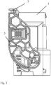
- Figur 1
- ein Steckverbindergehäuse mit einem Verbindungshebel in einer Anfangsstellung,
- Figur 2
- ein Steckverbindergehäuse mit einem Verbindungshebel in einer Endstellung,
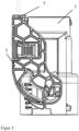
- Figur 3
- ein Steckverbindergehäuse mit einem Verbindungshebel in der Endstellung mit einem gesetzten Verriegelungselement,
- Figur 4
- eine Ansicht gemäß der
Figur 1 aus einer anderen Perspektive, - Figur 5
- eine Ansicht gemäß der
Figur 2 aus einer anderen Perspektive, - Figur 6
- eine Ansicht gemäß der
Figur 3 aus einer anderen Perspektive, - Figur 7
- die Einzelteile eines Verriegelungselements,
- Figur 8
- die miteinander verbundenen Einzelteile des Verriegelungselements,
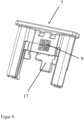
- Figur 9
- ein Verriegelungselement mit einem optischen Code,
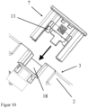
- Figur 10
- das Verriegelungselement beim Anfügen an das Steckverbindergehäuse,
- Figur 11
- das an das Steckverbindergehäuse angefügte Verriegelungselement,
- Figur 12
- das an das Steckverbindergehäuse angefügte entsperrte Verriegelungselement,
- Figur 13
- einen Verriegelungsklip in einer ersten Position,
- Figur 14
- einen Verriegelungsklip in einer zweiten Position,
- Figur 15
- eine Schnittansicht durch ein Steckverbindergehäuse gemäß der
Figur 6 , - Figur 16
- eine erste alternative Ausführung des Steckverbinders mit einem entsperrten Verriegelungselement,
- Figur 17
- die erste alternative Ausführung des Steckverbinders mit einem gesperrten Verriegelungselement,
- Figur 18
- eine zweite alternative Ausführung des Steckverbinders mit einem entsperrten Verriegelungselement und einem zusätzlichen DataMatrix-Code,
- Figur 19
- die zweite alternative Ausführung des Steckverbinders mit einem gesperrten Verriegelungselement und einem zusätzlichen DataMatrix-Code,
- Figur 20
- eine dritte alternative Ausführung des Steckverbinders mit einem entsperrten Verriegelungselement und einem zusätzlichen DataMatrix-Code auf dem Verriegelungselement,
- Figur 21
- die dritte alternative Ausführung des Steckverbinders mit einem gesperrten Verriegelungselement und einem zusätzlichen DataMatrix-Code auf dem Verriegelungselement.
- Die
Figuren 1 bis 6 zeigen jeweils ein Steckverbindergehäuse 1 mit einem Verbindungshebel 3. Der Verbindungshebel 3 besteht aus zwei seitlichen Hebelteilen 4, die über eine Verbindungssteg 2 miteinander verbunden sind und an zwei Seitenflächen des Steckverbindergehäuses 1 jeweils um einen Drehzapfen 6 drehbar gelagert sind. - In den
Figuren 1 bis 3 ist jeweils eines der Hebelteile 4 dargestellt. Die Hebelteile 4 weisen jeweils eine angeformte gebogene Führungsbahn 5 auf, in die jeweils ein Führungszapfen eines - in den Figuren nicht dargestellten - Gegensteckverbindergehäuses eingesetzt werden kann. - Bei einer Verdrehung des Verbindungshebels 3 von einer in der
Figur 1 dargestellten Anfangsstellung zu einer in derFigur 2 abgebildeten Endstellung werden das Steckverbindergehäuse und das Gegensteckverbindergehäuse mechanisch einander angenähert und die in den Gehäusen angeordneten elektrischen Kontaktelemente elektrisch miteinander verbunden. - Das Verbinden eines Steckverbindergehäuses mit einem Gegensteckverbindergehäuse mittels eines Drehhebels ist hier bildlich nicht im Detail dargestellt, da dieser Vorgang als bekannt vorausgesetzt werden kann. Er wird beispielsweise anhand der
Figur 3 der bereits genannten DruckschriftDE 20 2016 008 846 U1 dargestellt und beschrieben. - Die
Figuren 4 bis 6 zeigen entsprechende Ansichten eines um 90 ° gedrehten Steckverbindergehäuses 1, in denen jeweils beide Hebelteile 4 und der Verbindungssteg 2 zwischen den Hebelteilen 4 erkennbar ist. - In der in den
Figuren 1 und4 dargestellten Anfangsstellung des Verbindungshebels 3 können Führungszapfen eines Gegensteckverbindergehäuses in die Führungsbahnen 5 der Hebelteile 4 eingesetzt werden. - Nach dem Verschwenken des Verbindungshebels 3 in die in den
Figuren 2 und5 abgebildete Endstellung sind das Steckverbindergehäuse 1 und das - hier nicht dargestellte - Gegensteckverbindergehäuse bereits vollständig miteinander verbunden. Allerdings ist der Verbindungshebel 3 hier noch nicht am Steckverbindergehäuse 1 gesichert. - Das Sichern des Verbindungshebels 3 am Steckverbindergehäuse 1 erfolgt mittels eines verschiebbar am Verbindungshebel 3 angeordneten Verriegelungselements 7.
- Die
Figuren 3 und6 zeigen das Steckverbindergehäuse 1, wie bereits dieFiguren 2 und5 , ebenfalls mit dem Verbindungshebels 3 in seiner Endstellung. Zusätzlich ist das Verriegelungselement 7 hier durch das Hineindrücken in den Verbindungssteg 2 in eine Position gebracht worden, in der es den Verbindungshebel 3 am Steckverbindergehäuse 1 arretiert. Diese Position des Verriegelungselements 7 wird im Folgenden als Verriegelungsstellung bezeichnet. Das Verriegelungselement 7 erfüllt damit die bekannte Funktion eines Gehäusesicherungs- oder CPA-Riegels (CPA = "Connector Position Assurance"). - Wesentlich ist, dass das Verriegelungselement 7 einen optischen Code 9 aufweist, anhand dessen eine optische Leseeinrichtung die korrekte Position des Verriegelungselements 7 am Verbindungshebel 3 erkennen kann, und zwar ohne dass dabei Mittel erforderlich sind, die den optischen Codes 9 abdecken oder freigeben.
- Um dieses zu erreichen, ist vorgesehen, dass das Verriegelungselement 7 aus zwei gegeneinander verschiebbaren Teilen 8a, 8b besteht, von denen beide jeweils nur einen Teilabschnitt 9a, 9b des optischen Codes 9 tragen, so dass in einer Verschiebestellung der beiden Teile 8a, 8b relativ zueinander, die beiden Teilabschnitte 9a, 9b des optischen Codes 9 unterbrechungsfrei angeordnet sind.
- Wie die
Figur 6 zeigt, weist das Verriegelungselement 7 in der Verriegelungsstellung 7 einen optischen Code 9 auf. Dieser optische Code 9 kann insbesondere ein geometrisches Symbol, ein eindimensionaler Barcode oder, wie hier dargestellt, ein zweidimensionaler DataMatrix-Code sein. Ein derartiger optischer Code 9 kann durch eine hier nicht dargestellte optische Leseeinrichtung automatisch erfasst werden. - Unter einem geometrischen Symbol soll hier ein vorzugsweise einfach strukturiertes Bildzeichen verstanden werden, welches etwa als ein buchstabenartiges Zeichen oder auch als eine geometrische Figur, wie beispielsweise ein Kreis, Dreieck oder Rechteck ausgebildet sein kann.
- Ein vollständiges Symbol besteht üblicherweise aus einer oder mehreren Linien oder Flächen. Im Falle mehrerer Linien oder Flächen müssen diese nicht notwendigerweise miteinander in Verbindung stehen, sondern können auch in einer vorgesehenen geometrischen Anordnung zueinander stehen, wie etwa parallel zueinander oder miteinander fluchtend oder in einer unterbrechungsfreien Anordnung. Als Beispiel für ein derartiges Symbol sei ein Gleichheitszeichen genannt, welches aus einer parallelen Anordnung zweier paralleler Geraden gesteht.
- Insbesondere kann auch vorgesehen sein, dass mehrere Linien und/oder Flächen bestimmte Abstände zueinander einhalten müssen, um ein vollständiges Symbol zu bilden. Das Vorliegen dieser Eigenschaften kann etwa durch die Leseeinrichung geprüft werden, indem diese das erfasste Symbol mit einer vorab abgespeicherten Repräsentation des Symbols vergleicht.
- Befindet sich das Verriegelungselement 7 bei umgelegtem Verbindungshebel 3 nicht in der Verriegelungsstellung, wie es in der
Figur 5 dargestellt ist, so ist der optische Code 9 in zwei getrennte Teilabschnitte 9a, 9b unterteilt, die durch die optische Leseeinrichtung nicht als ein gültiger optischer Code 9 erkannt werden. - Bei nicht oder nicht vollständig umgelegtem Verbindungshebel 3, wie etwa in der
Figur 4 dargestellt, erscheint überhaupt kein optischer Code 9 in dem Bereich, der durch die optische Leseeinrichtung erfasst wird. - Das Verriegelungselement 7 mit dem optischen Code 9 wird nachfolgend anhand der
Figuren 7 bis 12 näher erläutert. - Wie die
Figur 7 zeigt, ist das Verriegelungselement 7 aus zwei einzelnen Teilen 8a, 8b aufgebaut. Hierbei weist ein erstes Teil 8a des Verriegelungselements 7 die Form eines Steges auf, an dessen einer Längsseite zwei Federhaken 10 und an dessen anderer Längsseite zwei Rasthaken 13 angeformt sind. - Das zweite Teil 8b des Verriegelungselements 7 weist zwei zueinander parallele Führungen 15 auf, die über einen Quersteg 12 miteinander verbunden sind und in die jeweils eine Führungsnut 16 eingeformt ist. In die beiden Führungsnuten 16 kann das erste Teil 8a verschiebbar eingesetzt werden. Der Quersteg 12 besitzt zwischen den Führungen 15 zwei Ausnehmungen 11.
- Gemäß dem in der
Figur 8 dargestellten Montagezustand des Verbindungselements 7 sind die Randabschnitte des ersten Teils 8a in die Führungen 15 des zweiten Teils 8b eingesetzt und das erste Teil 8a bis zum Anschlag an den Quersteg 12 des zweiten Teils 8b geschoben. Hierdurch sind die Endabschnitte der Federhaken 10 in die Ausnehmungen 11 des Querstegs 12 am zweiten Teil 8b eingerastet. Das erste und zweite Teil 8a, 8b sind somit miteinander verbunden, wodurch die Außenfläche des ersten Teils 8a nahezu übergangslos und fluchtend an der Außenfläche des Querstegs 12 anliegt. - Auf die so miteinander verbundenen Teile 8a, 8b wird in einem folgenden Fertigungsschritt des Verriegelungselements 7 ein optischer Code 9 aufgelasert, und zwar derart, dass sich die Ausdehnung des optischen Codes 9 von der Au ßenfläche des Querstegs 12 bis auf die Au ßenfläche des ersten Teils 8a erstreckt.
- Der optische Code 9 kann beispielsweise ein binärer eindimensionaler oder auch zweidimensionaler Code sein, der hier vereinfachend als Barcode beziehungsweise als DataMatrix-Code bezeichnet wird. Vorzugsweise bildet der optische Code 9 so einen das Verriegelungselement 7 individualisierenden Code aus, anhand dessen jedes einzelne Verriegelungselement 7 unterschieden und falls nötig wiedererkannt werden kann.
- Das fertiggestellte Verriegelungselement 7, welches die
Figur 9 zeigt, wird anschließend am Verbindungssteg 2 des Verbindungshebels 3 montiert (Figur 10 ). Hierbei rasten die am ersten Teil 8a des Verriegelungselements 7 angeformten Rasthaken 13 in Rastausnehmungen 14 am Verbindungshebel 3 ein. Dabei wird der optische Code 9 in einem Fensterspalt 18 am Verbindungshebel 3 erkennbar. - Da die Rasthaken 13 wesentlich materialstärker ausgeführt sind als die Federhaken 10 bewirken sie eine starke und nahezu untrennbare Verbindung zwischen dem Verriegelungselement 7 und dem Verbindungshebel 3.
- Im Gegensatz dazu ist die Haltekraft zwischen den Federhaken 10 und den Ausnehmungen 11 am zweiten Teil 8b des Verriegelungselements 7 wesentlicher geringer, so dass diese Rastverbindung mit einer händisch gut aufzubringenden Kraft getrennt werden kann.
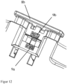
- Bei diesem Vorgang wird das zweite Teil 8b gegen das erste Teil 8a des Verriegelungselements 7 verschoben, während das erste Teil des Verriegelungselements 7 am Verbindungshebel 3 verbleibt. Hierdurch ergibt sich die in der
Figur 12 dargestellte Position des ersten und des zweiten Teils 8a, 8b relativ zueinander, in der der vorher vollständige optische Code 9 nun in zwei voneinander getrennte Teilabschnitte 9a, 9b unterteilt ist. - Wenn sich der Verbindungshebel 3 in seiner Endstellung befindet (dargestellt in den
Figuren 2 ,3 ,5 und6 ), so können die beiden gegeneinander verschiebbaren Teile 8a, 8b den Verbindungshebel 3 am Steckverbindergehäuse 1 entweder arretieren oder auch freigeben. Dieses wird durch einen am zweiten Teil 8b des Verriegelungselements 7 angeformten Verriegelungsklip 17 (Figur 9 ) bewirkt. - Wie die
Figuren 13 und14 in jeweils einer Schnittansicht durch das Steckverbindergehäuse 1 zeigen, verschiebt sich der Verriegelungsklip 17 zusammen dem zweiten Teil 8b des Verriegelungselements 7, wobei in der in derFigur 14 dargestellten Verriegelungsstellung sich ein äußerer Abschnitt 19 des Verriegelungsklips 17 zwischen zwei am Steckverbindergehäuse 1 angeformten Rastfedern 20 befindet und so die beiden Rastfedern 20 auseinanderdrückt. - Die
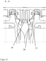
Figur 15 verdeutlicht den in derFigur 14 dargestellten Montagezustand anhand einer um 90 ° gedrehten Darstellung, die sich als Schnitt A - A der Ansicht auf das Steckverbindergehäuse 1 gemäß derFigur 6 ergibt. - Aus der
Figur 15 ist ersichtlich, dass die beiden durch den äußeren Abschnitt 19 des Verriegelungsklips 17 auseinandergedrückten Rastfedern 20 zwei Gehäuseabschnitte 21 arretieren, welche zum Steckverbindergehäuse 1 gehören. Hierdurch ist die Drehbeweglichkeit des Verbindungshebels 3 aufgehoben, so dass dieser in seiner an das Steckverbindergehäuse 1 angeklappten Stellung verbleibt solange sich das Verriegelungselement 7 in der Verriegelungsstellung befindet. Das Verriegelungselement 7 erfüllt damit seine Funktion als Positionssicherungs- oder CPA-Riegel. - Die
Figuren 16 und 17 verdeutlichen anhand einer weiteren Ausführung des Steckverbinders, dass der optische Code 9 nicht unbedingt ein Barcode oder DataMatrix-Code sein muss, sondern auch durch ein einfaches Symbol 22 gebildet sein kann. Das Symbol 22 kann dabei prinzipiell durch jede unterscheidbare Darstellung realisiert sein. Besonders vorteilhaft kann das Symbol als eine einfache geometrische Figur ausgeführt sein, was nachfolgend als "geometrisches Symbol" bezeichnet wird. - Das geometrische Symbol 22 besteht hier beispielhaft aus einer Rechteckfläche mit festgelegten Abmessungen und/oder Proportionen. Die Rechteckfläche ist in zwei Teilabschnitte 22a, 22b unterteilt, die auf zwei Teilen 8a, 8b des Verriegelungselements 7 angeordnet sind und die beim Zusammenführen der Teile 8a und 8b zu einem vollständigen geometrischen Symbol 22 in Form einer vervollständigten Rechteckfläche zusammengefügt werden.
- Alternativ kann das geometrische Symbol 22 auch durch eine Kreisfläche, Dreiecksfläche oder sonstige geometrische Form gebildet sein, die in Teilabschnitte unterteilt ist, und die durch das Zusammenführen der Teile 8a und 8b vervollständigt wird.
- Eine derartige Ausführung ist besonders vorteilhaft, da die Erkennung eines aus Teilabschnitten 22a, 22b zusammengesetzten geometrischen Symbols 22 weit weniger toleranzempfindlich ist, als die korrekte Erkennung eines aus Teilabschnitten 9a, 9b zusammengefügten DataMatrix- oder Barcodes.
- Wie in den
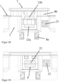
Figuren 18 und 19 angedeutet, kann zusätzlich ein ungeteilter DataMatrix- oder Barcode 23 auf einem Teil des Steckverbindergehäuses 1 oder des Verbindungshebels 3 angeordnet sein, um eine individualisierende Erfassung des Steckverbinders zu ermöglichen. - Dieser DataMatrix- oder Barcode 23 wird allerdings erst dann von einer Leseeinrichtung gelesen und/oder als gültig akzeptiert, wenn von dieser vorher ein vollständig zusammengefügtes geometrisches Symbol 22 erkannt wurde.
- Eine weitere Ausführung des Steckverbinders ist in den
Figuren 20 und 21 dargestellt. Ein zusätzlicher DataMatrix-Code 23 ist hier auf dem beweglichen Teil 8b des Verriegelungselements 7 angeordnet. Der DataMatrix- Code 23 wird auch hier erst dann von einer Leseeinrichtung gelesen und/oder als gültig akzeptiert, wenn von dieser vorher ein aus zwei Teilabschnitten 22a, 22b vollständig zusammengefügtes geometrisches Symbol 22 erkannt wurde. -
- 1
- Steckverbindergehäuse
- 2
- Verbindungssteg
- 3
- Verbindungshebel
- 4
- Hebelteile
- 5
- Führungsbahnen
- 6
- Drehzapfen
- 7
- Verriegelungselement
- 8a
- erstes Teil (des Verriegelungselements)
- 8b
- zweites Teil (des Verriegelungselements)
- 9
- optischer Code
- 9a, 9b
- Teilabschnitte (des optischen Codes)
- 10
- Federhaken
- 11
- Ausnehmungen
- 12
- Quersteg
- 13
- Rasthaken
- 14
- Rastausnehmung
- (13, 14)
- Rastmittel
- 15
- Führungen
- 16
- Führungsnuten
- 17
- Verriegelungsklip
- 18
- Fensterspalt
- 19
- äußerer Abschnitt
- 20
- Rastfedern
- 21
- Gehäuseabschnitte
- 22
- Symbol
- 22a, 22b
- Teilabschnitte
- 23
- (ungeteilter) DataMatrix- oder Barcode
Claims (8)
- Elektrischer Steckverbinder mit einem Steckverbindergehäuse (1), wobei an dem Steckverbindergehäuse (1) ein Verbindungshebel (3) mit zwei miteinander verbundenen parallelen Hebelteilen (4) angeordnet ist, der gegenüber dem Steckverbindergehäuse (1) zwischen einer Anfangsstellung und einer Endstellung verdreht und/oder verschoben werden kann,wobei die Hebelteile (4) jeweils eine Führungsbahn (5) aufweisen, in die in der Anfangsstellung des Verbindungshebel (3) jeweils ein an einem anfügbaren Gegensteckverbindergehäuse angeformter Führungszapfen eingesetzt und durch eine Drehung und/oder Verschiebung des Verbindungshebel (3) in der Führungsbahn (5) verschoben werden kann,wobei der Verbindungshebel (3) ein gegen das Steckverbindergehäuse (1) verschiebbares Verriegelungselement (7) aufweist, welches in einer als Verriegelungsstellung bezeichneten Verschiebeposition den sich in seiner Endstellung befindlichen Verbindungshebel (3) mechanisch am Steckverbindergehäuse (1) arretiert, undwobei das Verriegelungselement (7) einen optischen Code (9) trägt, welcher durch eine optische Leseeinrichtung genau dann vollständig erfassbar und decodierbar ist, wenn sich das Verriegelungselement (7) in der Verriegelungsstellung befindet,dadurch gekennzeichnet,dass das Verriegelungselement (7) aus zwei gegeneinander verschiebbaren Teilen (8a, 8b) besteht, von denen beide jeweils einen Teilabschnitt (9a, 9b) des optischen Codes (9) tragen,dass in einer Verschiebestellung der beiden Teile (8a, 8b) der optische Code (9) vervollständigt ist, unddass eines der Teile (8a) durch Rastmittel (13,14) am Verbindungshebel (3) fixiert ist.
- Elektrischer Steckverbinder nach Anspruch 1, dadurch gekennzeichnet, dass der optische Code (9) ein Barcode ist.
- Elektrischer Steckverbinder nach Anspruch 1, dadurch gekennzeichnet, dass der optische Code (9) ein DataMatrix-Code ist.
- Elektrischer Steckverbinder nach Anspruch 1, dadurch gekennzeichnet, dass der optische Code (9) ein Symbol (22) ist.
- Elektrischer Steckverbinder nach Anspruch 4, dadurch gekennzeichnet, dass das Symbol (22) eine geometrische Figur oder ein Schriftzeichen ist.
- Elektrischer Steckverbinder nach Anspruch 4 oder 5, dadurch gekennzeichnet, dass ein zusätzlicher und ungeteilter Barcode oder DataMatrix-Code (23) oder ein sonstiger scanbarer Code auf dem Steckverbindergehäuse (1) oder dem Verbindungshebel (3) oder auf einem Teil (8a, 8b) des Verriegelungselements (7) angeordnet ist.
- Elektrischer Steckverbinder nach Anspruch 1, dadurch gekennzeichnet, dass der optische Code (9) auf die beiden gegeneinander verschiebbaren Teile (8a, 8b) des Verriegelungselements (7) aufgelasert ist.
- Elektrischer Steckverbinder nach Anspruch 1, dadurch gekennzeichnet, dass der optische Code (9) auf die beiden gegeneinander verschiebbaren Teile (8a, 8b) des Verriegelungselements (7) aufgedruckt oder als Aufkleber aufgebracht ist.
Applications Claiming Priority (3)
| Application Number | Priority Date | Filing Date | Title |
|---|---|---|---|
| DE102021000345 | 2021-01-23 | ||
| DE102021005000.2A DE102021005000A1 (de) | 2021-01-23 | 2021-10-06 | Elektrischer Steckverbinder |
| PCT/EP2022/051220 WO2022157238A1 (de) | 2021-01-23 | 2022-01-20 | Elektrischer steckverbinder |
Publications (2)
| Publication Number | Publication Date |
|---|---|
| EP4282035A1 EP4282035A1 (de) | 2023-11-29 |
| EP4282035B1 true EP4282035B1 (de) | 2024-12-11 |
Family
ID=80953597
Family Applications (1)
| Application Number | Title | Priority Date | Filing Date |
|---|---|---|---|
| EP22713268.5A Active EP4282035B1 (de) | 2021-01-23 | 2022-01-20 | Elektrischer steckverbinder |
Country Status (7)
| Country | Link |
|---|---|
| US (1) | US12542399B2 (de) |
| EP (1) | EP4282035B1 (de) |
| JP (1) | JP7539586B2 (de) |
| KR (1) | KR20230132576A (de) |
| ES (1) | ES3015708T3 (de) |
| MX (1) | MX2023008591A (de) |
| WO (1) | WO2022157238A1 (de) |
Families Citing this family (6)
| Publication number | Priority date | Publication date | Assignee | Title |
|---|---|---|---|---|
| JP2022147207A (ja) * | 2021-03-23 | 2022-10-06 | 住友電装株式会社 | レバー式コネクタ |
| DE102023114790B3 (de) | 2023-06-06 | 2024-12-12 | Lisa Dräxlmaier GmbH | Sicherungsvorrichtung mit anzeigeelement und optisch veränderndem element |
| DE102023114793B3 (de) * | 2023-06-06 | 2024-12-12 | Lisa Dräxlmaier GmbH | Sicherungsvorrichtung mit anzeigeelement und orientierungselementen |
| DE102023114789B3 (de) | 2023-06-06 | 2024-10-02 | Lisa Dräxlmaier GmbH | Sicherungsvorrichtung mit in absoluter lage zueinander angeordneten erkennungsmerkmal und verdeckungsmerkmal |
| DE102023114792B3 (de) * | 2023-06-06 | 2024-10-02 | Lisa Dräxlmaier GmbH | Sicherungsvorrichtung mit anzeigeelement und kontrastelement |
| DE102023114791B3 (de) | 2023-06-06 | 2024-10-02 | Lisa Dräxlmaier GmbH | Sicherungsvorrichtung mit erkennungsmerkmal als teil eines zweiten erkennungsmerkmals |
Citations (2)
| Publication number | Priority date | Publication date | Assignee | Title |
|---|---|---|---|---|
| JP2006351275A (ja) * | 2005-06-14 | 2006-12-28 | Ricoh Co Ltd | 接続装置とこれを用いる検査システム及び画像形成装置 |
| CN108292818A (zh) * | 2015-11-24 | 2018-07-17 | 泰连公司 | 具有可记录的位置确保的电连接器 |
Family Cites Families (8)
| Publication number | Priority date | Publication date | Assignee | Title |
|---|---|---|---|---|
| JP3419715B2 (ja) * | 1999-10-14 | 2003-06-23 | 株式会社オートネットワーク技術研究所 | コネクタにおけるロック機構 |
| DE10143266B4 (de) | 2001-09-04 | 2004-01-29 | Conti Temic Microelectronic Gmbh | Steckeraufnehmer, Steckverbindung, Stecker sowie Gehäuse für eine elektrische Baugruppe mit einem solchen Steckeraufnehmer |
| JP2012038570A (ja) * | 2010-08-06 | 2012-02-23 | Japan Aviation Electronics Industry Ltd | 接続検出パターンを有するコネクタ |
| US9748695B2 (en) * | 2014-04-30 | 2017-08-29 | Ford Global Technologies, Llc | High voltage connector assembly |
| US9748693B1 (en) | 2016-02-10 | 2017-08-29 | Yazaki North America, Inc. | Connector position assurance with identification feature |
| US10651586B2 (en) * | 2018-06-01 | 2020-05-12 | Tyco Electronics Brasil Ltda | Electrical connector with machine-readable graphic identifier |
| US11296462B2 (en) * | 2019-10-10 | 2022-04-05 | Aptiv Technologies Limited | Connector assembly with a connector position assurance indicator |
| CN111755881B (zh) * | 2020-06-30 | 2022-08-19 | 联想(北京)有限公司 | 一种连接装置、系统、识别方法以及识别装置 |
-
2022
- 2022-01-20 WO PCT/EP2022/051220 patent/WO2022157238A1/de not_active Ceased
- 2022-01-20 EP EP22713268.5A patent/EP4282035B1/de active Active
- 2022-01-20 KR KR1020237028552A patent/KR20230132576A/ko active Pending
- 2022-01-20 ES ES22713268T patent/ES3015708T3/es active Active
- 2022-01-20 JP JP2023544223A patent/JP7539586B2/ja active Active
- 2022-01-20 MX MX2023008591A patent/MX2023008591A/es unknown
-
2023
- 2023-07-10 US US18/349,225 patent/US12542399B2/en active Active
Patent Citations (2)
| Publication number | Priority date | Publication date | Assignee | Title |
|---|---|---|---|---|
| JP2006351275A (ja) * | 2005-06-14 | 2006-12-28 | Ricoh Co Ltd | 接続装置とこれを用いる検査システム及び画像形成装置 |
| CN108292818A (zh) * | 2015-11-24 | 2018-07-17 | 泰连公司 | 具有可记录的位置确保的电连接器 |
Also Published As
| Publication number | Publication date |
|---|---|
| US12542399B2 (en) | 2026-02-03 |
| MX2023008591A (es) | 2023-11-08 |
| US20230352879A1 (en) | 2023-11-02 |
| KR20230132576A (ko) | 2023-09-15 |
| WO2022157238A1 (de) | 2022-07-28 |
| JP7539586B2 (ja) | 2024-08-23 |
| EP4282035A1 (de) | 2023-11-29 |
| JP2024504359A (ja) | 2024-01-31 |
| ES3015708T3 (en) | 2025-05-07 |
Similar Documents
| Publication | Publication Date | Title |
|---|---|---|
| EP4282035A1 (de) | Elektrischer steckverbinder | |
| EP3880999A1 (de) | Verbindungseinheit | |
| EP2581991B1 (de) | Halterahmen für steckverbinder | |
| DE3437844C2 (de) | Elektrische Kontakteinrichtung zu einem Schließzylinder mit einem elektronisch/mechanischen Schlüssel | |
| EP3665748B1 (de) | Steckverbinderteil mit einem verriegelungselement | |
| DE19835517C1 (de) | Kontakteinrichtung | |
| DE102018128203A1 (de) | Elektrisches Steckverbinderteil und elektrisches Steckverbindungssystem mit Verriegelung | |
| LU92994B1 (de) | Tragschienenbaugruppe mit einem Bussystem und einem eine Leiterplatte aufweisenden Elektronikgerät | |
| DE102007018762A1 (de) | Elektrische Kontaktstruktur in isolierenden Gehäusen | |
| DE1665644C3 (de) | Elektrische Steckvorrichtung | |
| EP0999610B1 (de) | Verriegelbarer elektrischer Steckverbinder | |
| WO2023057426A1 (de) | Elektrischer steckverbinder | |
| DE102005038167A1 (de) | Elektrischer Steckverbinder | |
| WO2023133605A1 (de) | Steckerbaugruppe mit einem steckverbinder und einem gegensteckverbinder | |
| DE102023114789B3 (de) | Sicherungsvorrichtung mit in absoluter lage zueinander angeordneten erkennungsmerkmal und verdeckungsmerkmal | |
| EP3128528A1 (de) | Modulanordnung | |
| DE102011051567B4 (de) | Steckverbindungsanordnung mit einem Kodierelement | |
| DE102021005000A1 (de) | Elektrischer Steckverbinder | |
| EP3736918B1 (de) | Steckverbinder und optoelektronischer sensor | |
| DE69108634T2 (de) | Verriegelungsmechanismus für Steckverbinder. | |
| EP1072998B1 (de) | Kontaktiereinrichtung | |
| DE2353407B2 (de) | Permanent-magnetschluessel-betaetigbares drehzylinderschloss | |
| DE202019106239U1 (de) | Hochfrequenz-Prüfstiftvorrichtung | |
| DE2606698A1 (de) | Schloss | |
| DE102023114792B3 (de) | Sicherungsvorrichtung mit anzeigeelement und kontrastelement |
Legal Events
| Date | Code | Title | Description |
|---|---|---|---|
| STAA | Information on the status of an ep patent application or granted ep patent |
Free format text: STATUS: UNKNOWN |
|
| STAA | Information on the status of an ep patent application or granted ep patent |
Free format text: STATUS: THE INTERNATIONAL PUBLICATION HAS BEEN MADE |
|
| PUAI | Public reference made under article 153(3) epc to a published international application that has entered the european phase |
Free format text: ORIGINAL CODE: 0009012 |
|
| STAA | Information on the status of an ep patent application or granted ep patent |
Free format text: STATUS: REQUEST FOR EXAMINATION WAS MADE |
|
| 17P | Request for examination filed |
Effective date: 20230705 |
|
| AK | Designated contracting states |
Kind code of ref document: A1 Designated state(s): AL AT BE BG CH CY CZ DE DK EE ES FI FR GB GR HR HU IE IS IT LI LT LU LV MC MK MT NL NO PL PT RO RS SE SI SK SM TR |
|
| DAV | Request for validation of the european patent (deleted) | ||
| DAX | Request for extension of the european patent (deleted) | ||
| RAP1 | Party data changed (applicant data changed or rights of an application transferred) |
Owner name: KOSTAL KONTAKT SYSTEME GMBH & CO. KG |
|
| GRAP | Despatch of communication of intention to grant a patent |
Free format text: ORIGINAL CODE: EPIDOSNIGR1 |
|
| STAA | Information on the status of an ep patent application or granted ep patent |
Free format text: STATUS: GRANT OF PATENT IS INTENDED |
|
| GRAS | Grant fee paid |
Free format text: ORIGINAL CODE: EPIDOSNIGR3 |
|
| GRAA | (expected) grant |
Free format text: ORIGINAL CODE: 0009210 |
|
| STAA | Information on the status of an ep patent application or granted ep patent |
Free format text: STATUS: THE PATENT HAS BEEN GRANTED |
|
| INTG | Intention to grant announced |
Effective date: 20241010 |
|
| AK | Designated contracting states |
Kind code of ref document: B1 Designated state(s): AL AT BE BG CH CY CZ DE DK EE ES FI FR GB GR HR HU IE IS IT LI LT LU LV MC MK MT NL NO PL PT RO RS SE SI SK SM TR |
|
| REG | Reference to a national code |
Ref country code: GB Ref legal event code: FG4D Free format text: NOT ENGLISH |
|
| REG | Reference to a national code |
Ref country code: CH Ref legal event code: EP |
|
| REG | Reference to a national code |
Ref country code: IE Ref legal event code: FG4D Free format text: LANGUAGE OF EP DOCUMENT: GERMAN |
|
| REG | Reference to a national code |
Ref country code: DE Ref legal event code: R096 Ref document number: 502022002382 Country of ref document: DE |
|
| REG | Reference to a national code |
Ref country code: LT Ref legal event code: MG9D |
|
| PG25 | Lapsed in a contracting state [announced via postgrant information from national office to epo] |
Ref country code: HR Free format text: LAPSE BECAUSE OF FAILURE TO SUBMIT A TRANSLATION OF THE DESCRIPTION OR TO PAY THE FEE WITHIN THE PRESCRIBED TIME-LIMIT Effective date: 20241211 |
|
| PG25 | Lapsed in a contracting state [announced via postgrant information from national office to epo] |
Ref country code: FI Free format text: LAPSE BECAUSE OF FAILURE TO SUBMIT A TRANSLATION OF THE DESCRIPTION OR TO PAY THE FEE WITHIN THE PRESCRIBED TIME-LIMIT Effective date: 20241211 |
|
| PG25 | Lapsed in a contracting state [announced via postgrant information from national office to epo] |
Ref country code: BG Free format text: LAPSE BECAUSE OF FAILURE TO SUBMIT A TRANSLATION OF THE DESCRIPTION OR TO PAY THE FEE WITHIN THE PRESCRIBED TIME-LIMIT Effective date: 20241211 |
|
| REG | Reference to a national code |
Ref country code: NL Ref legal event code: MP Effective date: 20241211 |
|
| PG25 | Lapsed in a contracting state [announced via postgrant information from national office to epo] |
Ref country code: NO Free format text: LAPSE BECAUSE OF FAILURE TO SUBMIT A TRANSLATION OF THE DESCRIPTION OR TO PAY THE FEE WITHIN THE PRESCRIBED TIME-LIMIT Effective date: 20250311 |
|
| PG25 | Lapsed in a contracting state [announced via postgrant information from national office to epo] |
Ref country code: LV Free format text: LAPSE BECAUSE OF FAILURE TO SUBMIT A TRANSLATION OF THE DESCRIPTION OR TO PAY THE FEE WITHIN THE PRESCRIBED TIME-LIMIT Effective date: 20241211 Ref country code: GR Free format text: LAPSE BECAUSE OF FAILURE TO SUBMIT A TRANSLATION OF THE DESCRIPTION OR TO PAY THE FEE WITHIN THE PRESCRIBED TIME-LIMIT Effective date: 20250312 |
|
| PG25 | Lapsed in a contracting state [announced via postgrant information from national office to epo] |
Ref country code: RS Free format text: LAPSE BECAUSE OF FAILURE TO SUBMIT A TRANSLATION OF THE DESCRIPTION OR TO PAY THE FEE WITHIN THE PRESCRIBED TIME-LIMIT Effective date: 20250311 |
|
| PG25 | Lapsed in a contracting state [announced via postgrant information from national office to epo] |
Ref country code: NL Free format text: LAPSE BECAUSE OF FAILURE TO SUBMIT A TRANSLATION OF THE DESCRIPTION OR TO PAY THE FEE WITHIN THE PRESCRIBED TIME-LIMIT Effective date: 20241211 |
|
| PG25 | Lapsed in a contracting state [announced via postgrant information from national office to epo] |
Ref country code: SM Free format text: LAPSE BECAUSE OF FAILURE TO SUBMIT A TRANSLATION OF THE DESCRIPTION OR TO PAY THE FEE WITHIN THE PRESCRIBED TIME-LIMIT Effective date: 20241211 |
|
| PG25 | Lapsed in a contracting state [announced via postgrant information from national office to epo] |
Ref country code: PL Free format text: LAPSE BECAUSE OF FAILURE TO SUBMIT A TRANSLATION OF THE DESCRIPTION OR TO PAY THE FEE WITHIN THE PRESCRIBED TIME-LIMIT Effective date: 20241211 |
|
| PG25 | Lapsed in a contracting state [announced via postgrant information from national office to epo] |
Ref country code: IS Free format text: LAPSE BECAUSE OF FAILURE TO SUBMIT A TRANSLATION OF THE DESCRIPTION OR TO PAY THE FEE WITHIN THE PRESCRIBED TIME-LIMIT Effective date: 20250411 |
|
| PG25 | Lapsed in a contracting state [announced via postgrant information from national office to epo] |
Ref country code: PT Free format text: LAPSE BECAUSE OF FAILURE TO SUBMIT A TRANSLATION OF THE DESCRIPTION OR TO PAY THE FEE WITHIN THE PRESCRIBED TIME-LIMIT Effective date: 20250411 |
|
| PG25 | Lapsed in a contracting state [announced via postgrant information from national office to epo] |
Ref country code: EE Free format text: LAPSE BECAUSE OF FAILURE TO SUBMIT A TRANSLATION OF THE DESCRIPTION OR TO PAY THE FEE WITHIN THE PRESCRIBED TIME-LIMIT Effective date: 20241211 |
|
| PG25 | Lapsed in a contracting state [announced via postgrant information from national office to epo] |
Ref country code: RO Free format text: LAPSE BECAUSE OF FAILURE TO SUBMIT A TRANSLATION OF THE DESCRIPTION OR TO PAY THE FEE WITHIN THE PRESCRIBED TIME-LIMIT Effective date: 20241211 |
|
| PG25 | Lapsed in a contracting state [announced via postgrant information from national office to epo] |
Ref country code: SK Free format text: LAPSE BECAUSE OF FAILURE TO SUBMIT A TRANSLATION OF THE DESCRIPTION OR TO PAY THE FEE WITHIN THE PRESCRIBED TIME-LIMIT Effective date: 20241211 |
|
| REG | Reference to a national code |
Ref country code: CH Ref legal event code: PL |
|
| PG25 | Lapsed in a contracting state [announced via postgrant information from national office to epo] |
Ref country code: SE Free format text: LAPSE BECAUSE OF FAILURE TO SUBMIT A TRANSLATION OF THE DESCRIPTION OR TO PAY THE FEE WITHIN THE PRESCRIBED TIME-LIMIT Effective date: 20241211 |
|
| REG | Reference to a national code |
Ref country code: DE Ref legal event code: R097 Ref document number: 502022002382 Country of ref document: DE |
|
| PG25 | Lapsed in a contracting state [announced via postgrant information from national office to epo] |
Ref country code: MC Free format text: LAPSE BECAUSE OF FAILURE TO SUBMIT A TRANSLATION OF THE DESCRIPTION OR TO PAY THE FEE WITHIN THE PRESCRIBED TIME-LIMIT Effective date: 20241211 Ref country code: LU Free format text: LAPSE BECAUSE OF NON-PAYMENT OF DUE FEES Effective date: 20250120 |
|
| PG25 | Lapsed in a contracting state [announced via postgrant information from national office to epo] |
Ref country code: DK Free format text: LAPSE BECAUSE OF FAILURE TO SUBMIT A TRANSLATION OF THE DESCRIPTION OR TO PAY THE FEE WITHIN THE PRESCRIBED TIME-LIMIT Effective date: 20241211 |
|
| PG25 | Lapsed in a contracting state [announced via postgrant information from national office to epo] |
Ref country code: BE Free format text: LAPSE BECAUSE OF NON-PAYMENT OF DUE FEES Effective date: 20250131 |
|
| PLBE | No opposition filed within time limit |
Free format text: ORIGINAL CODE: 0009261 |
|
| STAA | Information on the status of an ep patent application or granted ep patent |
Free format text: STATUS: NO OPPOSITION FILED WITHIN TIME LIMIT |
|
| PG25 | Lapsed in a contracting state [announced via postgrant information from national office to epo] |
Ref country code: CH Free format text: LAPSE BECAUSE OF NON-PAYMENT OF DUE FEES Effective date: 20250131 |
|
| REG | Reference to a national code |
Ref country code: BE Ref legal event code: MM Effective date: 20250131 |
|
| 26N | No opposition filed |
Effective date: 20250912 |
|
| PG25 | Lapsed in a contracting state [announced via postgrant information from national office to epo] |
Ref country code: IE Free format text: LAPSE BECAUSE OF NON-PAYMENT OF DUE FEES Effective date: 20250120 |
|
| PGFP | Annual fee paid to national office [announced via postgrant information from national office to epo] |
Ref country code: CZ Payment date: 20251217 Year of fee payment: 5 |
|
| PGFP | Annual fee paid to national office [announced via postgrant information from national office to epo] |
Ref country code: GB Payment date: 20260123 Year of fee payment: 5 |
|
| PGFP | Annual fee paid to national office [announced via postgrant information from national office to epo] |
Ref country code: ES Payment date: 20260305 Year of fee payment: 5 |
|
| PGFP | Annual fee paid to national office [announced via postgrant information from national office to epo] |
Ref country code: DE Payment date: 20260128 Year of fee payment: 5 |
|
| PGFP | Annual fee paid to national office [announced via postgrant information from national office to epo] |
Ref country code: AT Payment date: 20260301 Year of fee payment: 5 |
|
| PGFP | Annual fee paid to national office [announced via postgrant information from national office to epo] |
Ref country code: IT Payment date: 20260127 Year of fee payment: 5 |
|
| PGFP | Annual fee paid to national office [announced via postgrant information from national office to epo] |
Ref country code: FR Payment date: 20260128 Year of fee payment: 5 |