EP4281639B1 - Selbstjustierendes schliessstück für eine schliesseinheit - Google Patents
Selbstjustierendes schliessstück für eine schliesseinheit Download PDFInfo
- Publication number
- EP4281639B1 EP4281639B1 EP22718998.2A EP22718998A EP4281639B1 EP 4281639 B1 EP4281639 B1 EP 4281639B1 EP 22718998 A EP22718998 A EP 22718998A EP 4281639 B1 EP4281639 B1 EP 4281639B1
- Authority
- EP
- European Patent Office
- Prior art keywords
- housing
- locking
- locking piece
- slide
- spring clip
- Prior art date
- Legal status (The legal status is an assumption and is not a legal conclusion. Google has not performed a legal analysis and makes no representation as to the accuracy of the status listed.)
- Active
Links
Images

Classifications
-
- E—FIXED CONSTRUCTIONS
- E05—LOCKS; KEYS; WINDOW OR DOOR FITTINGS; SAFES
- E05B—LOCKS; ACCESSORIES THEREFOR; HANDCUFFS
- E05B15/00—Other details of locks; Parts for engagement by bolts of fastening devices
- E05B15/02—Striking-plates; Keepers; Bolt staples; Escutcheons
- E05B15/0205—Striking-plates, keepers, staples
- E05B15/022—Striking-plates, keepers, staples movable, resilient or yieldable
-
- E—FIXED CONSTRUCTIONS
- E05—LOCKS; KEYS; WINDOW OR DOOR FITTINGS; SAFES
- E05B—LOCKS; ACCESSORIES THEREFOR; HANDCUFFS
- E05B15/00—Other details of locks; Parts for engagement by bolts of fastening devices
- E05B15/02—Striking-plates; Keepers; Bolt staples; Escutcheons
- E05B15/0205—Striking-plates, keepers, staples
- E05B15/024—Striking-plates, keepers, staples adjustable
- E05B15/0255—Deformable element
-
- E—FIXED CONSTRUCTIONS
- E05—LOCKS; KEYS; WINDOW OR DOOR FITTINGS; SAFES
- E05B—LOCKS; ACCESSORIES THEREFOR; HANDCUFFS
- E05B15/00—Other details of locks; Parts for engagement by bolts of fastening devices
- E05B15/02—Striking-plates; Keepers; Bolt staples; Escutcheons
- E05B15/0205—Striking-plates, keepers, staples
- E05B15/024—Striking-plates, keepers, staples adjustable
- E05B15/0245—Movable elements held by friction, cooperating teeth, or the like
-
- E—FIXED CONSTRUCTIONS
- E05—LOCKS; KEYS; WINDOW OR DOOR FITTINGS; SAFES
- E05B—LOCKS; ACCESSORIES THEREFOR; HANDCUFFS
- E05B15/00—Other details of locks; Parts for engagement by bolts of fastening devices
- E05B15/04—Spring arrangements in locks
-
- E—FIXED CONSTRUCTIONS
- E05—LOCKS; KEYS; WINDOW OR DOOR FITTINGS; SAFES
- E05B—LOCKS; ACCESSORIES THEREFOR; HANDCUFFS
- E05B47/00—Operating or controlling locks or other fastening devices by electric or magnetic means
- E05B47/0038—Operating or controlling locks or other fastening devices by electric or magnetic means using permanent magnets
-
- E—FIXED CONSTRUCTIONS
- E05—LOCKS; KEYS; WINDOW OR DOOR FITTINGS; SAFES
- E05B—LOCKS; ACCESSORIES THEREFOR; HANDCUFFS
- E05B65/00—Locks or fastenings for special use
- E05B65/44—Locks or fastenings for special use for furniture
-
- E—FIXED CONSTRUCTIONS
- E05—LOCKS; KEYS; WINDOW OR DOOR FITTINGS; SAFES
- E05B—LOCKS; ACCESSORIES THEREFOR; HANDCUFFS
- E05B15/00—Other details of locks; Parts for engagement by bolts of fastening devices
- E05B15/02—Striking-plates; Keepers; Bolt staples; Escutcheons
- E05B15/0205—Striking-plates, keepers, staples
- E05B15/024—Striking-plates, keepers, staples adjustable
- E05B2015/027—Striking-plates, keepers, staples adjustable auto-adjustable
-
- E—FIXED CONSTRUCTIONS
- E05—LOCKS; KEYS; WINDOW OR DOOR FITTINGS; SAFES
- E05B—LOCKS; ACCESSORIES THEREFOR; HANDCUFFS
- E05B15/00—Other details of locks; Parts for engagement by bolts of fastening devices
- E05B15/04—Spring arrangements in locks
- E05B2015/0458—Leaf springs; Non-wound wire springs
-
- E—FIXED CONSTRUCTIONS
- E05—LOCKS; KEYS; WINDOW OR DOOR FITTINGS; SAFES
- E05B—LOCKS; ACCESSORIES THEREFOR; HANDCUFFS
- E05B47/00—Operating or controlling locks or other fastening devices by electric or magnetic means
- E05B2047/0048—Circuits, feeding, monitoring
- E05B2047/0067—Monitoring
- E05B2047/0068—Door closed
-
- E—FIXED CONSTRUCTIONS
- E05—LOCKS; KEYS; WINDOW OR DOOR FITTINGS; SAFES
- E05B—LOCKS; ACCESSORIES THEREFOR; HANDCUFFS
- E05B63/00—Locks or fastenings with special structural characteristics
- E05B63/12—Locks or fastenings with special structural characteristics with means carried by the bolt for interlocking with the keeper
- E05B63/122—Locks or fastenings with special structural characteristics with means carried by the bolt for interlocking with the keeper with transverse, i.e. vertically movable bolt or dropbolt
-
- E—FIXED CONSTRUCTIONS
- E05—LOCKS; KEYS; WINDOW OR DOOR FITTINGS; SAFES
- E05B—LOCKS; ACCESSORIES THEREFOR; HANDCUFFS
- E05B65/00—Locks or fastenings for special use
- E05B65/46—Locks or fastenings for special use for drawers
Definitions
- the invention relates to a locking piece for a locking unit, with a housing which has a particularly rectangular housing opening, and with a slider arranged in the housing, which is guided on the housing side so as to be linearly displaceable between two end positions and has a locking arm which extends at right angles to the direction of displacement of the slider and protrudes forwards through the housing opening. Furthermore, the invention also relates to a locking unit with such a locking piece.
- Such a locking piece with a floating locking arm is, for example, DE 20 2018 106 887 U1 or US 2013/180991 A1 became known
- Revolving doors and drawers are usually mounted in the furniture using hinges or guides.
- the revolving doors, drawers of the furniture body and the fittings themselves are subject to tolerances due to installation. Furthermore, a certain amount of settling cannot be ruled out over time due to the use and loading/operation of the doors and drawers in the furniture.
- This means that the locking piece may not move sufficiently into the lock mouth or may not be able to be brought into the closed position or may only be done with difficulty. The locking piece is then no longer aligned with the lock mouth. It is therefore necessary to provide the locking piece with adjustability, e.g. in the form of elongated holes, so that the locking arm can always be (re)adjusted to the desired position relative to the lock mouth. Such adjustment work is relatively laborious and time-consuming.
- the known locking piece for a locking unit comprises a housing with a housing opening, a locking arm which passes through the housing opening and is mounted in the housing opening so that it can move in a direction perpendicular to its longitudinal direction, and a slider which is guided in the housing so that it can move in the direction of movement of the locking arm and which is coupled in terms of movement to the locking arm in the direction of movement.
- the housing and/or the slider are made of magnetically attractable material, and at least one magnet acts between the housing and the slider, which fixes the locking arm in position in every possible position within the housing opening.
- the floating mounting of the slider ensures that the locking arm connected to the slider always assumes the optimal position in the lock mouth of a lock and also maintains this optimal position.
- the invention is based on the object of specifying an alternative fastening of the slide in the housing in a self-adjusting, position-holding locking piece of the type mentioned at the beginning.
- the fastening should be able to be designed with as few parts as possible.
- a spring clip is arranged behind the slide, which extends along the direction of displacement and is anchored at its two clip ends in the housing, wherein the slide is arranged between the housing and the spring clip and is held in contact with the housing by the spring clip.
- the floating locking arm adjusts itself in relation to the position of the lock mouth when it is inserted into the lock mouth of a lock.
- the slider is pressed against the housing by the spring clip in such a way that the slider is fixed in position in each of its possible displacement positions along the displacement direction.
- the locking arm After extending from the lock mouth, the locking arm is held in the adjusted position on the housing by the spring clip through friction, which holds the locking arm in each possible displacement position within the housing opening or fixes it in position.
- a continuous displacement of the slider and the locking arm is possible by applying a force in the displacement direction to the locking arm and thus to the slider, which overcomes the friction.
- the slider has a recess that is open at the back and in which a permanent magnet is accommodated, which is gripped by the spring clip and thus held in the recess.
- the permanent magnet works together with a reed contact of the lock to detect the locking arm in the lock.
- the spring clip engages in a rear longitudinal groove of the slider running in the direction of displacement, whereby the slider and spring clip are mutually guided.
- the two ends of the bracket are each angled in a hook shape
- the spring bracket viewed from the rear, engages behind the housing with its two forward-facing, hook-shaped ends of the bracket.
- the housing viewed in the direction of displacement, preferably has a fastening hole on each side of the housing opening, with the two hook-shaped ends of the bracket reaching through the fastening holes and enclosing the housing wall of the fastening holes.
- the housing wall of the fastening holes can advantageously each have a groove into which the hook-shaped ends of the bracket engage.
- the spring clip is C-shaped and can advantageously be a wire clip or a sheet metal strip clip.
- the slide is guided so as to be displaceable on the inside of the housing and/or in the housing opening.
- the slide has a base section that is wider than the housing opening and an intermediate section arranged between the base section and the locking arm, which carries the locking arm and is at most as wide as the housing opening.
- the locking arm is also wider than the housing opening.
- the housing opening viewed in a direction perpendicular to the sliding direction, has a keyhole recess on one or both sides, through which the locking arm is inserted into its outwardly projecting position.
- the locking arm can be designed as a locking bracket or locking eyelet.
- the invention also relates to a locking unit - e.g. mechanical or electronic - with a lock having a lock mouth, in particular a furniture lock, and with a locking piece designed as above, the locking arm of which engages in the lock mouth in the closed position of the lock and is locked.
- the locking arm in the lock mouth is continuously moved in the direction of displacement against the frictional forces caused by the spring clip into the correct position, which is then held by the spring clip.
- the lock preferably has a reed contact that interacts with the permanent magnet of the locking piece. When the locking arm engages in the lock mouth, the reed contact is activated by the permanent magnet of the locking piece and the locking arm in the lock mouth is thereby detected.
- the Figs. 1 and 2 shown locking piece 1 for a locking unit 20 has a housing 2 with a rectangular housing opening 3 , for example, and a slide 4 arranged in the housing 2, which is guided on the housing side so as to be linearly displaceable between two end positions in the vertical displacement direction (double arrow) 5.
- the slide 4 has a locking arm (e.g. locking bracket or locking eyelet) 6, which extends at right angles to the displacement direction 5 and projects forwards through the housing opening 3.
- the slide 4 can be guided so as to be displaceable on the inside of the housing 2 and/or in the housing opening 3.
- a spring clip 7 (e.g. wire clip or sheet metal strip clip) is arranged behind the slide 4, which extends along the direction of displacement 5 and is anchored at its two clip ends 8 in the housing 2.
- the slide 4 is arranged between the housing 2 and the spring clip 7 and is held in contact with the housing 2 by the spring clip 7.
- the floating slide 4 is preferably pressed against the housing 2 by the spring clip 7 so strongly that the slide 4 is fixed in position in each of its possible displacement positions along the direction of displacement 5 by the acting frictional force.
- the slide 4 has a recess 9 that is open at the back and in which a permanent magnet 10 is accommodated.
- the spring clip 7 engages behind the permanent magnet 10 and is thereby held in the recess 9.
- the slide 4 can have a longitudinal groove 11 on the back that runs in the direction of displacement 5 and into which the spring clip 7 is inserted.
- the locking arm 6 is held in position by the frictional connection between the spring clip 7 and the permanent magnet 10 and between the locking arm 6 and the housing 2. In embodiments without a permanent magnet, the locking arm 6 is held in position by the frictional connection between the spring clip 7 and the locking arm 6 and between the locking arm 6 and the housing 2.
- the spring clip 7 is preferably C-shaped with two hook-shaped angled clip ends 8.
- the two hook-shaped clip ends 8 are directed forwards and reach through fastening holes 12 of the housing 2, which, viewed in the direction of displacement 5, are arranged on both sides of the housing opening 3.
- the two hook-shaped clip ends 8 surround the wall of the fastening holes 12 and, viewed from the rear, reach behind the housing 2.
- the walls of the fastening holes 12 can each have a groove 13 into which the hook-shaped bracket ends 8 engage.
- the locking piece 1 is screwed to a door, for example, via the fastening holes 12. Alternatively, the locking piece 1 can also be glued to the door, so that in this case the housing does not need to have any screw holes.
- the slide 4 can have a base section 4a and an intermediate section 4b arranged between the base section 4a and the locking arm 6, which carries the locking arm 6.
- the base section 4a and the locking arm 6 each have a width B1, B2 , viewed at right angles to the direction of displacement 5, which is greater than the width B of the housing opening 3 (B1, B2 > B).
- the width B3 of the intermediate section 4b is at most as wide as the width B of the rectangular housing opening 3 (B3 ⁇ B).
- the housing opening 3 viewed in the direction at right angles to the direction of displacement 5, has a keyhole recess 14 on both sides, through which the locking arm 6 is inserted into its outwardly projecting position and can then be moved on the housing 2 in the direction of displacement 5.
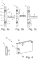
- the locking arm 6 is located in Fig. 3a in its middle sliding position in the housing opening 3, which is marked by a dotted line, in Fig. 3b in its upper end position, pushed up from the middle shift position by +Z (e.g. 2.5 mm), and in Fig. 3c in its lower end position, pushed down from the middle sliding position by -Z (e.g. 2.5 mm). In each of its possible sliding positions along the sliding direction 5, the locking arm 6 is held in position by the spring clip 7.
- the in Fig. 4 The locking unit 20 shown consists of a mechanically or electronically actuated furniture lock 21 with a lock mouth 22 and the locking piece 1 according to the invention, the locking arm 6 of which engages in the lock mouth 22 in the closed position of the furniture lock 21 and is locked therein.
- the height-adjustable locking arm 6 adjusts itself when moving into the Lock mouth 22 in relation to its height position and remains in the adjusted position after moving out of the lock mouth 22 by the spring clip 7.
- a reed contact (monitoring contact) 23 arranged on the lock mouth 22 is actuated by the permanent magnet 10 of the locking piece 1 in order to detect the locking arm 6 located in the lock mouth 22. In this way, it can be determined whether the door/drawer/flap etc. on which the furniture lock 21 or the locking piece 1 is mounted is open or closed.
- Fig. 4 the locking arm 6 is moved from the front side into the lock mouth 22 of the furniture lock 21, i.e. in the longitudinal direction of the furniture lock 21, e.g. in a sliding door.
- the locking piece 1 it is also possible to arrange the locking piece 1 to the side of the furniture lock 21, so that the locking arm 6 is moved into the lock mouth 22 from the side, i.e. in the transverse direction of the furniture lock 21, e.g. in a swing door.
Landscapes
- Clamps And Clips (AREA)
- Lock And Its Accessories (AREA)
- Closures For Containers (AREA)
Description
- Die Erfindung betrifft ein Schließstück für eine Schließeinheit, mit einem Gehäuse, das eine insbesondere rechteckige Gehäuseöffnung aufweist, und mit einem im Gehäuse angeordneten Schieber, der gehäuseseitig zwischen zwei Endpositionen linear verschiebbar geführt ist und einen Schließarm aufweist, welcher sich rechtwinklig zur Verschieberichtung des Schiebers erstreckt und durch die Gehäuseöffnung hindurch nach vorne vorsteht. Ferner betrifft die Erfindung auch eine Schließeinheit mit einem solchen Schließstück.
- Ein solches Schließstück mit einem schwimmend gelagerten Schließarm ist beispielsweise durch die
DE 20 2018 106 887 U1 oderUS 2013/180991 A1 bekannt geworden - Drehtüren und Schubladen werden in der Regel über Scharniere bzw. Führungen im Möbel gelagert. Die Drehtüren, Schubladen des Möbelkorpus sowie die Beschläge selbst sind einbaubedingt mit Toleranzen behaftet. Des Weiteren ist durch die Nutzung und Beladung/Betätigung der Türen und Schubladen im Möbel über die Zeit ein gewisses Setzverhalten nicht auszuschließen. Dadurch ist es möglich, dass das Schließstück nicht ausreichend in den Schlossmund einfährt oder nicht oder nur schwer in Schließstellung gebracht werden kann. Das Schließstück fluchtet dann nicht mehr mit dem Schlossmund. Es ist daher erforderlich, beim Schließstück eine Verstellbarkeit, z.B. in Form von Langlöchern, vorzusehen, damit der Schließarm stets in die gewünschte Lage relativ zum Schlossmund (nach)justiert werden kann. Derartige Justierarbeiten sind verhältnismäßig mühsam durchzuführen und zeitaufwendig.
- Das aus der eingangs genannten
DE 20 2018 106 887 U1 bekannte Schließstück für eine Schließeinheit umfasst ein Gehäuse mit einer Gehäuseöffnung, einen Schließarm, der die Gehäuseöffnung durchgreift und in der Gehäuseöffnung in Richtung rechtwinklig zu seiner Längsrichtung verschiebbar gelagert ist, und einen im Gehäuse in der Verschieberichtung des Schließarms verschiebbar geführten Schieber, der mit dem Schließarm in der Verschieberichtung bewegungsgekoppelt ist. Das Gehäuse und/oder der Schieber sind aus magnetisch anziehbarem Material gebildet, und zwischen Gehäuse und Schieber wirkt mindestens ein Magnet, der den Schließarm in jeder innerhalb der Gehäuseöffnung möglichen Verschiebeposition lagefixiert. Durch die schwimmende Lagerung des Schiebers ist sichergestellt, dass der mit dem Schieber verbundene Schließarm stets die optimale Lage im Schlossmund eines Schlosses einnimmt und diese optimale Lage auch beibehält. - Der Erfindung liegt demgegenüber die Aufgabe zugrunde, bei einem selbstjustierenden, positionshaltenden Schließstück der eingangs genannten Art eine alternative Befestigung des Schiebers im Gehäuse anzugeben. Insbesondere soll die Befestigung mit möglichst wenig Teilen ausgebildet werden können.
- Diese Aufgabe wird bei dem Schließstück der eingangs genannten Art erfindungsgemäß dadurch gelöst, dass hinter dem Schieber ein Federbügel angeordnet ist, der sich entlang der Verschieberichtung erstreckt und an seinen beiden Bügelenden im Gehäuse verankert ist, wobei der Schieber zwischen dem Gehäuse und dem Federbügel angeordnet und von dem Federbügel in Anlage an dem Gehäuse gehalten ist.
- Erfindungsgemäß ist zur Befestigung des Schiebers nur ein einziges Teil, nämlich der Federbügel, erforderlich. Der schwimmend gelagerte Schließarm justiert sich beim Einfahren in den Schlossmund eines Schlosses in Bezug auf die Position des Schlossmundes selbst.
- Besonders bevorzugt ist der Schieber von dem Federbügel derart in Anlage gegen das Gehäuse gedrückt, dass der Schieber in jeder seiner entlang der Verschieberichtung möglichen Verschiebepositionen lagefixiert ist. Der Schließarm wird nach dem Ausfahren aus dem Schlossmund von dem Federbügel in der justierten Stellung am Gehäuse durch Reibschluss gehalten, der den Schließarm in jeder innerhalb der Gehäuseöffnung möglichen Verschiebeposition hält bzw. lagefixiert. Eine stufenlose Verschiebung des Schiebers und des Schließarms ist durch eine den Reibschluss überwindende Krafteinwirkung in Verschieberichtung auf den Schließarm und damit auf den Schieber möglich.
- Vorzugsweise weist der Schieber eine rückseitig offene Aussparung auf, in der ein Permanentmagnet aufgenommen ist, welcher von dem Federbügel hintergriffen und dadurch in der Aussparung gehalten ist. Der Permanentmagnet wirkt mit einem Reedkontakt des Schlosses zusammen, um den Schließarm im Schloss zu detektieren.
- Vorzugsweise greift der Federbügel in eine in der Verschieberichtung verlaufende, rückseitige Längsnut des Schiebers ein, wodurch Schieber und Federbügel gegenseitig geführt sind.
- In einer bevorzugten Ausführungsform des erfindungsgemäßen Schließstücks sind die beiden Bügelenden jeweils hakenförmig abgewinkelt, und der Federbügel hintergreift, gesehen in Richtung nach hinten, mit seinen beiden nach vorne gerichteten, hakenförmigen Bügelenden das Gehäuse. Vorzugsweise weist das Gehäuse, gesehen in der Verschieberichtung, zu beiden Seiten der Gehäuseöffnung jeweils ein Befestigungsloch auf, wobei die beiden hakenförmigen Bügelenden durch die Befestigungslöcher hindurchgreifen und die Gehäusewandung der Befestigungslöcher umgreifen. Vorteilhaft kann die Gehäusewandung der Befestigungslöcher jeweils eine Nut aufweisen, in welche die hakenförmigen Bügelenden eingreifen.
- Besonders bevorzugt ist der Federbügel C-förmig ausgebildet und kann vorteilhaft ein Drahtbügel oder ein Blechstreifenbügel sein.
- Vorzugsweise ist der Schieber innen am Gehäuse und/oder in der Gehäuseöffnung verschiebbar geführt.
- In einer bevorzugten Ausführungsform des erfindungsgemäßen Schließstücks weist der Schieber einen Fußabschnitt, der breiter als die Gehäuseöffnung ist, und einen zwischen Fußabschnitt und Schließarm angeordneten Zwischenabschnitt auf, der den Schließarm trägt und höchstens so breit wie die Gehäuseöffnung ist. In einer Weiterbildung ist auch der Schließarm breiter als die Gehäuseöffnung. Auf Höhe einer insbesondere mittleren Verschiebestellung des Schiebers weist die Gehäuseöffnung, gesehen in Richtung rechtwinklig zur Verschieberichtung, einoder beidseitig eine Schlüssellochaussparung auf, durch die hindurch der Schließarm bis in seine nach außen vorstehende Stellung gesteckt ist.
- Vorteilhaft kann der Schließarm als Schließbügel oder Schließöse ausgebildet sein.
- Die Erfindung betrifft auch eine - z.B. mechanische oder elektronische - Schließeinheit mit einem einen Schlossmund aufweisenden Schloss, insbesondere Möbelschloss, und mit einem wie oben ausgebildeten Schließstück, dessen Schließarm in der Schließposition des Schlosses in den Schlossmund eingreift und darin verriegelt ist. Erfindungsgemäß wird der Schließarm im Schlossmund gegen die vom Federbügel bewirkten Reibungskräfte stufenlos in Verschieberichtung in die jeweils korrekte Position verschoben, die dann vom Federbügel gehalten bleibt. Vorzugsweise weist das Schloss einen Reedkontakt auf, der mit dem Permanentmagneten des Schließstücks zusammenwirkt. Wenn der Schließarm in den Schlossmund eingreift, wird der Reed-Kontakt vom Permanentmagnet des Schließstücks betätigt und dadurch der im Schlossmund befindliche Schließarm detektiert.
- Weitere Vorteile der Erfindung ergeben sich aus der Beschreibung, den Ansprüchen und der Zeichnung. Die gezeigte und beschriebene Ausführungsform ist nicht abschließend zu verstehen, sondern hat vielmehr beispielhaften Charakter für die Schilderung der Erfindung.
- Es zeigen:
- Fig. 1
- eine Explosionsdarstellung des erfindungsgemäßen Schließstücks mit einem schwimmend gelagerten, höhenverschiebbaren Schließarm;
- Fign. 2a-2e
- das erfindungsgemäße Schließstück in einer Frontansicht (
Fig. 2a ), in einer Seitenansicht (Fig. 2b ), in einer Rückansicht (Fig. 2c ), in einer Ansicht von oben oder unten (Fig. 2d ) und in einer perspektivischen Ansicht (Fig. 2e ); - Fign. 3a-3c
- das erfindungsgemäße Schließstück mit dem Schließarm in einer mittleren Position (
Fig. 3a ), in einer oberen Endstellung (Fig. 3b ) und in einer unteren Endstellung (Fig. 3c ), jeweils im Längsschnitt; und - Fig. 4
- eine Schließeinheit mit einem Möbelschloss und dem erfindungsgemäßen Schließstück.
- Das in
Fign. 1 und 2 gezeigte Schließstück 1 für eine Schließeinheit 20 (Fig. 4 ) weist ein Gehäuse 2 mit einer z.B. rechteckigen Gehäuseöffnung 3 und einen im Gehäuse 2 angeordneten Schieber 4 auf, der gehäuseseitig zwischen zwei Endpositionen linear in der hier vertikalen Verschieberichtung (Doppelpfeil) 5 verschiebbar geführt ist. Der Schieber 4 hat einen Schließarm (z.B. Schließbügel oder Schließöse) 6, der sich rechtwinklig zur Verschieberichtung 5 erstreckt und durch die Gehäuseöffnung 3 hindurch nach vorne vorsteht. Der Schieber 4 kann innen am Gehäuse 2 und/oder in der Gehäuseöffnung 3 verschiebbar geführt sein. - Hinter dem Schieber 4 ist ein Federbügel 7 (z.B. Drahtbügel oder Blechstreifenbügel) angeordnet, der sich entlang der Verschieberichtung 5 erstreckt und an seinen beiden Bügelenden 8 im Gehäuse 2 verankert ist. Der Schieber 4 ist zwischen Gehäuse 2 und Federbügel 7 angeordnet und von dem Federbügel 7 in Anlage an dem Gehäuse 2 gehalten. Vorzugsweise ist der schwimmend gelagerte Schieber 4 von dem Federbügel 7 derart stark in Anlage gegen das Gehäuse 2 gedrückt, dass der Schieber 4 in jeder seiner entlang der Verschieberichtung 5 möglichen Verschiebepositionen durch die wirkende Reibungskraft lagefixiert ist.
- Der Schieber 4 weist eine rückseitig offene Aussparung 9 auf, in der ein Permanentmagnet 10 aufgenommen ist. Der Permanentmagnet 10 wird von dem Federbügel 7 hintergriffen und dadurch in der Aussparung 9 gehalten. Der Schieber 4 kann rückseitig eine in der Verschieberichtung 5 verlaufende Längsnut 11 aufweisen, in die der Federbügel 7 eingelegt ist. Der Schließarm 6 wird durch den Reibschluss zwischen Federbügel 7 und Permanentmagnet 10 sowie zwischen Schließarm 6 und Gehäuse 2 in Position gehalten. In Ausführungsformen ohne Permanentmagnet wird der Schließarm 6 durch den Reibschluss zwischen Federbügel 7 und Schließarm 6 sowie zwischen Schließarm 6 und Gehäuse 2 in Position gehalten.
- Wie in
Fig. 1 gezeigt, ist der Federbügel 7 bevorzugt C-förmig mit zwei hakenförmig abgewinkelten Bügelenden 8 ausgebildet. Die beiden hakenförmigen Bügelenden 8 sind nach vorne gerichtet und greifen durch Befestigungslöcher 12 des Gehäuses 2 hindurch, die, gesehen in der Verschieberichtung 5, zu beiden Seiten der Gehäuseöffnung 3 angeordnet sind. Die beiden hakenförmigen Bügelenden 8 umgreifen die Wandung der Befestigungslöcher 12 und hintergreifen, gesehen in Richtung nach hinten, das Gehäuse 2. Die Wandungen der Befestigungslöcher 12 können jeweils eine Nut 13 aufweisen, in welche die hakenförmigen Bügelenden 8 eingreifen. Über die Befestigungslöcher 12 wird das Schließstück 1 z.B. an eine Tür angeschraubt. Alternativ kann das Schließstück 1 aber auch an die Tür aufgeklebt werden, so dass in diesem Fall das Gehäuse keine Schraublöcher aufzuweisen braucht. - Wie in
Fig. 1 weiter gezeigt, kann der Schieber 4 einen Fußabschnitt 4a und einen zwischen Fußabschnitt 4a und Schließarm 6 angeordneten Zwischenabschnitt 4b aufweisen, der den Schließarm 6 trägt. Der Fußabschnitt 4a und der Schließarm 6 weisen, gesehen rechtwinklig zur Verschieberichtung 5, jeweils eine Breite B1, B2 auf, die größer als die Breite B der Gehäuseöffnung 3 ist (B1, B2 > B). Die Breite B3 des Zwischenabschnitts 4b ist höchstens so breit wie die Breite B der rechteckigen Gehäuseöffnung 3 (B3 ≤ B). Auf Höhe einer - hier der mittleren - Verschiebestellung des Schiebers 4 weist die Gehäuseöffnung 3, gesehen in Richtung rechtwinklig zur Verschieberichtung 5, beidseitig eine Schlüssellochaussparung 14 auf, durch die hindurch der Schließarm 6 bis in seine nach außen vorstehende Stellung gesteckt wird und dann auf dem Gehäuse 2 in Verschieberichtung 5 verschoben werden kann. - Der Schließarm 6 befindet sich in
Fig. 3a in seiner in der Gehäuseöffnung 3 mittleren Verschiebeposition, die durch eine strichpunktierte Linie gekennzeichnet ist, inFig. 3b in seiner aus der mittleren Verschiebeposition um +Z (z.B. 2,5 mm) hochgeschobenen, oberen Endposition und inFig. 3c in seiner aus der mittleren Verschiebeposition um -Z (z.B. 2,5 mm) heruntergeschobenen, unteren Endposition. In jeder seiner entlang der Verschieberichtung 5 möglichen Verschiebepositionen ist der Schließarm 6 durch den Federbügel 7 lagefixiert gehalten. - Die in
Fig. 4 gezeigte Schließeinheit 20 besteht aus einem mechanisch oder elektronisch betätigbaren Möbelschloss 21 mit einem Schlossmund 22 und dem erfindungsgemäßen Schließstück 1, dessen Schließarm 6 in der Schließposition des Möbelschlosses 21 in den Schlossmund 22 eingreift und darin verriegelt ist. Der höhenverschiebbare Schließarm 6 justiert sich beim Hineinbewegen in den Schlossmund 22 in Bezug auf dessen Höhenposition selbst und bleibt nach dem Herausbewegen aus dem Schlossmund 22 durch den Federbügel 7 in der justierten Stellung gehalten. Wenn der Schließarm 6 in den Schlossmund 22 hineinbewegt wird, wird ein am Schloßmund 22 angeordneter Reed-Kontakt (Überwachungskontakt) 23 vom Permanentmagnet 10 des Schließstücks 1 betätigt, um so den im Schlossmund 22 befindlichen Schließarm 6 zu detektieren. So kann festgestellt werden, ob die Türe/ Schublade/ Klappe etc., an der das Möbelschloss 21 bzw. das Schließstück 1 montiert ist, offen oder geschlossen ist. - In
Fig. 4 wird der Schließarm 6 von der Stirnseite her in den Schlossmund 22 des Möbelschlosses 21 hineinbewegt, also in Längsrichtung des Möbelschlosses 21, z.B. bei einer Schiebetür. Es ist aber auch möglich, das Schließstück 1 seitlich des Möbelschlosses 21 anzuordnen, so dass der Schließarm 6 von der Seite her in den Schlossmund 22 eingefahren wird, also in Querrichtung des Möbelschlosses 21, z.B. bei einer Schwenktür.
Claims (15)
- Schließstück (1) für eine Schließeinheit (20), mit einem Gehäuse (2), das eine insbesondere rechteckige Gehäuseöffnung (3) aufweist, und mit einem im Gehäuse (2) angeordneten Schieber (4), der gehäuseseitig zwischen zwei Endpositionen linear verschiebbar geführt ist und einen Schließarm (6) aufweist, welcher sich rechtwinklig zur Verschieberichtung (5) des Schiebers (4) erstreckt und durch die Gehäuseöffnung (3) hindurch nach vorne vorsteht,
dadurch gekennzeichnet,
dass hinter dem Schieber (4) ein Federbügel (7) angeordnet ist, der sich entlang der Verschieberichtung (5) erstreckt und an seinen beiden Bügelenden (8) im Gehäuse (2) verankert ist, wobei der Schieber (4) zwischen dem Gehäuse (2) und dem Federbügel (7) angeordnet und von dem Federbügel (7) in Anlage an dem Gehäuse (2) gehalten ist. - Schließstück nach Anspruch 1, dadurch gekennzeichnet, dass der Schieber (4) von dem Federbügel (7) derart in Anlage gegen das Gehäuse (2) gedrückt ist, dass der Schieber (4) in jeder seiner entlang der Verschieberichtung (5) möglichen Verschiebepositionen lagefixiert ist.
- Schließstück nach Anspruch 1 oder 2, dadurch gekennzeichnet, dass der Schieber (4) eine rückseitig offene Aussparung (9) aufweist, in der ein Permanentmagnet (10) aufgenommen ist, welcher von dem Federbügel (7) hintergriffen und in der Aussparung (9) gehalten ist.
- Schließstück nach einem der vorhergehenden Ansprüche, dadurch gekennzeichnet, dass der Federbügel (7) in eine in der Verschieberichtung (5) verlaufende, rückseitige Längsnut (11) des Schiebers (4) eingreift.
- Schließstück nach einem der vorhergehenden Ansprüche, dadurch gekennzeichnet, dass die beiden Bügelenden (8) jeweils hakenförmig abgewinkelt sind und der Federbügel (7) mit seinen beiden nach vorne gerichteten, hakenförmigen Bügelenden (8) das Gehäuse (2), gesehen in Richtung nach hinten, hintergreift.
- Schließstück nach Anspruch 5, dadurch gekennzeichnet, dass das Gehäuse (2), gesehen in der Verschieberichtung (5), zu beiden Seiten der Gehäuseöffnung (3) jeweils ein Befestigungsloch (12) aufweist und die beiden hakenförmigen Bügelenden (8) durch die Befestigungslöcher (12) hindurchgreifen und die Gehäusewandung der Befestigungslöcher (12) umgreifen.
- Schließstück nach Anspruch 6, dadurch gekennzeichnet, dass die Gehäusewandung der Befestigungslöcher (12) jeweils eine Nut (13) aufweisen, in welche die hakenförmigen Bügelenden (8) eingreifen.
- Schließstück nach einem der vorhergehenden Ansprüche, dadurch gekennzeichnet, dass der Federbügel (7) C-förmig ausgebildet ist.
- Schließstück nach einem der vorhergehenden Ansprüche, dadurch gekennzeichnet, dass der Federbügel (7) ein Drahtbügel oder ein Blechstreifenbügel ist.
- Schließstück nach einem der vorhergehenden Ansprüche, dadurch gekennzeichnet, dass der Schieber (4) innen am Gehäuse (2) und/oder in der Gehäuseöffnung (3) verschiebbar geführt ist.
- Schließstück nach einem der vorhergehenden Ansprüche, dadurch gekennzeichnet, dass der Schieber (4) einen Fußabschnitt (4a), der breiter als die Gehäuseöffnung (3) ist, und einen zwischen Fußabschnitt (4a) und Schließarm (6) angeordneten Zwischenabschnitt (4b) aufweist, der den Schließarm (6) trägt und höchstens so breit wie die Gehäuseöffnung (3) ist.
- Schließstück nach Anspruch 11, dadurch gekennzeichnet, dass der Schließarm (6) breiter als die Gehäuseöffnung (3) ist und dass auf Höhe einer, insbesondere mittleren Verschiebestellung des Schiebers (4) die Gehäuseöffnung (3), gesehen in Richtung rechtwinklig zur Verschieberichtung (5), ein- oder beidseitig eine Schlüssellochaussparung (14) aufweist, durch die hindurch der Schließarm (6) bis in seine nach außen vorstehende Stellung gesteckt ist.
- Schließstück nach einem der vorhergehenden Ansprüche, dadurch gekennzeichnet, dass der Schließarm (6) als Schließbügel oder Schließöse ausgebildet ist.
- Schließeinheit (20) mit einem einen Schlossmund (22) aufweisenden Schloss (21), insbesondere Möbelschloss, und mit einem Schließstück (1) nach einem der vorhergehenden Ansprüche, dessen Schließarm (6) in der Schließposition des Schlosses (21) in den Schlossmund (22) eingreift und darin verriegelt ist.
- Schließeinheit nach Anspruch 14 und mit einem Schließstück (1) nach mindestens Anspruch 3, dadurch gekennzeichnet, dass das Schloss (21) einen Reedkontakt (23) aufweist, der mit dem Permanentmagneten (10) des Schließstücks (1) zusammenwirkt.
Applications Claiming Priority (2)
| Application Number | Priority Date | Filing Date | Title |
|---|---|---|---|
| DE202021102083.0U DE202021102083U1 (de) | 2021-04-19 | 2021-04-19 | Selbstjustierendes Schließstück für eine Schließeinheit |
| PCT/EP2022/059800 WO2022223379A1 (de) | 2021-04-19 | 2022-04-12 | Selbstjustierendes schliessstück für eine schliesseinheit |
Publications (3)
| Publication Number | Publication Date |
|---|---|
| EP4281639A1 EP4281639A1 (de) | 2023-11-29 |
| EP4281639B1 true EP4281639B1 (de) | 2024-10-23 |
| EP4281639B8 EP4281639B8 (de) | 2024-12-18 |
Family
ID=75962897
Family Applications (1)
| Application Number | Title | Priority Date | Filing Date |
|---|---|---|---|
| EP22718998.2A Active EP4281639B8 (de) | 2021-04-19 | 2022-04-12 | Selbstjustierendes schliessstück für eine schliesseinheit |
Country Status (6)
| Country | Link |
|---|---|
| US (1) | US12503881B2 (de) |
| EP (1) | EP4281639B8 (de) |
| CN (1) | CN117321278A (de) |
| DE (1) | DE202021102083U1 (de) |
| ES (1) | ES3001143T3 (de) |
| WO (1) | WO2022223379A1 (de) |
Families Citing this family (1)
| Publication number | Priority date | Publication date | Assignee | Title |
|---|---|---|---|---|
| CN115182654B (zh) * | 2022-06-07 | 2025-04-29 | 浙江极氪智能科技有限公司 | 一种自调节车门锁扣总成及其安装方法和车辆 |
Family Cites Families (19)
| Publication number | Priority date | Publication date | Assignee | Title |
|---|---|---|---|---|
| US2681245A (en) * | 1950-04-15 | 1954-06-15 | John W J Ackermans | Frictional floating mechanism for door mounting and retaining and the like |
| US6715808B2 (en) * | 2000-02-22 | 2004-04-06 | Atoma International Corp. | Power striker mechanism with backdrive prevention |
| US6666487B2 (en) * | 2000-02-25 | 2003-12-23 | Atoma International Corp. | Power striker with toggle linkage drive mechanism |
| AU3824802A (en) * | 2001-05-08 | 2002-11-14 | Westinghouse Air Brake Technologies Corporation | Latch door |
| GB0223618D0 (en) * | 2002-10-11 | 2002-11-20 | Arvinmeritor Light Vehicle Sys | Latch assembly, latch and striker |
| AU2006331283A1 (en) | 2005-12-29 | 2007-07-05 | Telezygology Inc | Pin assembly |
| US8047582B1 (en) * | 2006-12-23 | 2011-11-01 | Securitron Magnalock Corporation | Electro-mechanical lock |
| DE202008004173U1 (de) | 2008-03-26 | 2009-08-06 | Hoppe Ag, St. Martin | Verriegelungsvorrichtung |
| US20120001443A1 (en) * | 2009-02-23 | 2012-01-05 | Endura Products, Inc. | Multi-Point Locking System and Astragal |
| EP2449193A4 (de) * | 2009-06-12 | 2014-12-03 | Raymond A & Cie | Kraft-cinching-türgriff |
| US9297183B2 (en) * | 2010-03-01 | 2016-03-29 | Daws Manufacturing Company, Inc. | Self-adjusting striker assembly |
| JP5633313B2 (ja) * | 2010-11-04 | 2014-12-03 | アイシン精機株式会社 | 車両ドア固定装置、その可動楔装置及びその組み付け方法 |
| JP5915025B2 (ja) * | 2010-12-27 | 2016-05-11 | アイシン精機株式会社 | 車両ドアの固定装置、及び車両ドアの可動楔装置 |
| KR101215262B1 (ko) * | 2012-06-05 | 2012-12-24 | 장근대 | 사물함용 잠금장치 |
| DE102012013702A1 (de) | 2012-07-10 | 2014-01-16 | Gantner Electronic Gmbh | Elektronische Schließeinheit für den Schrank einer Mehrfach-Schließanlage |
| FR3010116A1 (fr) * | 2013-09-03 | 2015-03-06 | Peugeot Citroen Automobiles Sa | Gache destinee a cooperer avec la serrure d'un ouvrant de vehicule automobile |
| JP7028806B2 (ja) * | 2016-06-29 | 2022-03-02 | サウスコ,インコーポレイティド | ラッチ組立体に使用するためのストライカ |
| DE202018106887U1 (de) | 2018-12-04 | 2019-01-23 | Sphinx Electronics Gmbh & Co. Kg | Selbstjustierendes Schließstück für eine Schließeinheit |
| DE102021101888A1 (de) * | 2020-02-06 | 2021-08-12 | Magna BÖCO GmbH | SCHLIEßBÜGELANORDNUNG FÜR DIE VERSCHLUSSVERRIEGELUNG IN KRAFTFAHRZEUGEN |
-
2021
- 2021-04-19 DE DE202021102083.0U patent/DE202021102083U1/de active Active
-
2022
- 2022-04-12 EP EP22718998.2A patent/EP4281639B8/de active Active
- 2022-04-12 WO PCT/EP2022/059800 patent/WO2022223379A1/de not_active Ceased
- 2022-04-12 CN CN202280029601.8A patent/CN117321278A/zh active Pending
- 2022-04-12 ES ES22718998T patent/ES3001143T3/es active Active
-
2023
- 2023-10-16 US US18/487,289 patent/US12503881B2/en active Active
Also Published As
| Publication number | Publication date |
|---|---|
| DE202021102083U1 (de) | 2021-05-04 |
| EP4281639A1 (de) | 2023-11-29 |
| WO2022223379A1 (de) | 2022-10-27 |
| CN117321278A (zh) | 2023-12-29 |
| ES3001143T3 (es) | 2025-03-04 |
| EP4281639B8 (de) | 2024-12-18 |
| US20240060331A1 (en) | 2024-02-22 |
| US12503881B2 (en) | 2025-12-23 |
Similar Documents
| Publication | Publication Date | Title |
|---|---|---|
| EP3891351B1 (de) | Selbstjustierendes schliessstück für eine schliesseinheit | |
| WO2009076785A1 (de) | Vorrichtung zum einziehen und dämpfen einer in einer profilschiene zum führen von laufwerken getragenen schiebetür in die endlage | |
| WO2006066774A1 (de) | Schliess-und öffnungsvorrichtung für schubladen | |
| DE102009016427B4 (de) | Verfahren zum Bedienen einer Schublade | |
| EP1817983A1 (de) | Vorrichtung zur Beeinflussung der Bewegung von relativ zueinander bewegbaren Möbelteilen und Schubladenführung sowie Verfahren zu deren Herstellung | |
| EP2811092A2 (de) | Tür oder Fenster mit einem Schwenkbeschlag | |
| DE102015106854A1 (de) | Vorrichtung und Verfahren zum Festlegen eines Schubelementes | |
| EP3147435B1 (de) | Ausziehsperrvorrichtung und möbel | |
| EP3417134B1 (de) | Beschlaganordnung zur anbindung eines schieb- und kippbaren flügels | |
| EP3291702B1 (de) | Möbel und verfahren zum festlegen eines schubkastens | |
| EP3201412A1 (de) | Führungseinrichtung zur führung einer schiebetür und schrankmöbel | |
| DE102010038247B4 (de) | Schließsystem eines ausziehbaren Möbelteils und Möbel | |
| EP1647206B1 (de) | Teleskopierbare Auszugschiene für ein ausziehbares Möbelteil | |
| EP2630320B1 (de) | Schubladenbeschlag zum anbinden einer schublade an einen zentralverschluss | |
| EP2241219A2 (de) | Schließ- und/oder Einzugsvorrichtung für bewegbare Möbelteile | |
| EP4281639A1 (de) | Selbstjustierendes schliessstück für eine schliesseinheit | |
| EP2405095A2 (de) | Türdichtung mit Befestigungselement | |
| DE69503828T2 (de) | Blokiervorrichtung für eine Verlängerung Bezüglich eines Möbelstückes, und Möbelstück damit Ausgestattet | |
| DE102014216722B4 (de) | Steuerelement für eine Beschlaganordnung | |
| WO2017072106A1 (de) | Führungsanordnung für schiebetüren und schrankmöbel | |
| EP3424401A1 (de) | Vorrichtung zur abgabe von reinigungsmittel | |
| DE102018130012A1 (de) | Schubkasten und Möbel | |
| AT400795B (de) | Schublade | |
| DE102007010209B4 (de) | Antriebsvorrichtung | |
| DE19828233A1 (de) | Wandkonsole |
Legal Events
| Date | Code | Title | Description |
|---|---|---|---|
| STAA | Information on the status of an ep patent application or granted ep patent |
Free format text: STATUS: UNKNOWN |
|
| STAA | Information on the status of an ep patent application or granted ep patent |
Free format text: STATUS: THE INTERNATIONAL PUBLICATION HAS BEEN MADE |
|
| PUAI | Public reference made under article 153(3) epc to a published international application that has entered the european phase |
Free format text: ORIGINAL CODE: 0009012 |
|
| STAA | Information on the status of an ep patent application or granted ep patent |
Free format text: STATUS: REQUEST FOR EXAMINATION WAS MADE |
|
| 17P | Request for examination filed |
Effective date: 20230822 |
|
| AK | Designated contracting states |
Kind code of ref document: A1 Designated state(s): AL AT BE BG CH CY CZ DE DK EE ES FI FR GB GR HR HU IE IS IT LI LT LU LV MC MK MT NL NO PL PT RO RS SE SI SK SM TR |
|
| GRAP | Despatch of communication of intention to grant a patent |
Free format text: ORIGINAL CODE: EPIDOSNIGR1 |
|
| STAA | Information on the status of an ep patent application or granted ep patent |
Free format text: STATUS: GRANT OF PATENT IS INTENDED |
|
| DAV | Request for validation of the european patent (deleted) | ||
| DAX | Request for extension of the european patent (deleted) | ||
| INTG | Intention to grant announced |
Effective date: 20240531 |
|
| GRAS | Grant fee paid |
Free format text: ORIGINAL CODE: EPIDOSNIGR3 |
|
| GRAA | (expected) grant |
Free format text: ORIGINAL CODE: 0009210 |
|
| STAA | Information on the status of an ep patent application or granted ep patent |
Free format text: STATUS: THE PATENT HAS BEEN GRANTED |
|
| AK | Designated contracting states |
Kind code of ref document: B1 Designated state(s): AL AT BE BG CH CY CZ DE DK EE ES FI FR GB GR HR HU IE IS IT LI LT LU LV MC MK MT NL NO PL PT RO RS SE SI SK SM TR |
|
| REG | Reference to a national code |
Ref country code: GB Ref legal event code: FG4D Free format text: NOT ENGLISH |
|
| REG | Reference to a national code |
Ref country code: DE Ref legal event code: R081 Ref document number: 502022001972 Country of ref document: DE Owner name: HAEFELE TECHNOLOGY SOLUTIONS GMBH & CO KG, DE Free format text: FORMER OWNER: SPHINX ELECTRONICS GMBH & CO KG, 79341 KENZINGEN, DE |
|
| REG | Reference to a national code |
Ref country code: CH Ref legal event code: EP |
|
| REG | Reference to a national code |
Ref country code: DE Ref legal event code: R096 Ref document number: 502022001972 Country of ref document: DE |
|
| REG | Reference to a national code |
Ref country code: IE Ref legal event code: FG4D Free format text: LANGUAGE OF EP DOCUMENT: GERMAN |
|
| REG | Reference to a national code |
Ref country code: CH Ref legal event code: PK Free format text: BERICHTIGUNG B8 |
|
| RAP2 | Party data changed (patent owner data changed or rights of a patent transferred) |
Owner name: HAEFELE TECHNOLOGY SOLUTIONS GMBH & CO KG |
|
| REG | Reference to a national code |
Ref country code: LT Ref legal event code: MG9D |
|
| REG | Reference to a national code |
Ref country code: NL Ref legal event code: MP Effective date: 20241023 |
|
| REG | Reference to a national code |
Ref country code: ES Ref legal event code: FG2A Ref document number: 3001143 Country of ref document: ES Kind code of ref document: T3 Effective date: 20250304 |
|
| PG25 | Lapsed in a contracting state [announced via postgrant information from national office to epo] |
Ref country code: NL Free format text: LAPSE BECAUSE OF FAILURE TO SUBMIT A TRANSLATION OF THE DESCRIPTION OR TO PAY THE FEE WITHIN THE PRESCRIBED TIME-LIMIT Effective date: 20241023 |
|
| PG25 | Lapsed in a contracting state [announced via postgrant information from national office to epo] |
Ref country code: NL Free format text: LAPSE BECAUSE OF FAILURE TO SUBMIT A TRANSLATION OF THE DESCRIPTION OR TO PAY THE FEE WITHIN THE PRESCRIBED TIME-LIMIT Effective date: 20241023 |
|
| PG25 | Lapsed in a contracting state [announced via postgrant information from national office to epo] |
Ref country code: HR Free format text: LAPSE BECAUSE OF FAILURE TO SUBMIT A TRANSLATION OF THE DESCRIPTION OR TO PAY THE FEE WITHIN THE PRESCRIBED TIME-LIMIT Effective date: 20241023 Ref country code: IS Free format text: LAPSE BECAUSE OF FAILURE TO SUBMIT A TRANSLATION OF THE DESCRIPTION OR TO PAY THE FEE WITHIN THE PRESCRIBED TIME-LIMIT Effective date: 20250223 Ref country code: PT Free format text: LAPSE BECAUSE OF FAILURE TO SUBMIT A TRANSLATION OF THE DESCRIPTION OR TO PAY THE FEE WITHIN THE PRESCRIBED TIME-LIMIT Effective date: 20250224 |
|
| PG25 | Lapsed in a contracting state [announced via postgrant information from national office to epo] |
Ref country code: FI Free format text: LAPSE BECAUSE OF FAILURE TO SUBMIT A TRANSLATION OF THE DESCRIPTION OR TO PAY THE FEE WITHIN THE PRESCRIBED TIME-LIMIT Effective date: 20241023 |
|
| PG25 | Lapsed in a contracting state [announced via postgrant information from national office to epo] |
Ref country code: BG Free format text: LAPSE BECAUSE OF FAILURE TO SUBMIT A TRANSLATION OF THE DESCRIPTION OR TO PAY THE FEE WITHIN THE PRESCRIBED TIME-LIMIT Effective date: 20241023 |
|
| PG25 | Lapsed in a contracting state [announced via postgrant information from national office to epo] |
Ref country code: NO Free format text: LAPSE BECAUSE OF FAILURE TO SUBMIT A TRANSLATION OF THE DESCRIPTION OR TO PAY THE FEE WITHIN THE PRESCRIBED TIME-LIMIT Effective date: 20250123 |
|
| PG25 | Lapsed in a contracting state [announced via postgrant information from national office to epo] |
Ref country code: LV Free format text: LAPSE BECAUSE OF FAILURE TO SUBMIT A TRANSLATION OF THE DESCRIPTION OR TO PAY THE FEE WITHIN THE PRESCRIBED TIME-LIMIT Effective date: 20241023 Ref country code: GR Free format text: LAPSE BECAUSE OF FAILURE TO SUBMIT A TRANSLATION OF THE DESCRIPTION OR TO PAY THE FEE WITHIN THE PRESCRIBED TIME-LIMIT Effective date: 20250124 |
|
| PG25 | Lapsed in a contracting state [announced via postgrant information from national office to epo] |
Ref country code: PL Free format text: LAPSE BECAUSE OF FAILURE TO SUBMIT A TRANSLATION OF THE DESCRIPTION OR TO PAY THE FEE WITHIN THE PRESCRIBED TIME-LIMIT Effective date: 20241023 |
|
| PG25 | Lapsed in a contracting state [announced via postgrant information from national office to epo] |
Ref country code: RS Free format text: LAPSE BECAUSE OF FAILURE TO SUBMIT A TRANSLATION OF THE DESCRIPTION OR TO PAY THE FEE WITHIN THE PRESCRIBED TIME-LIMIT Effective date: 20250123 |
|
| PG25 | Lapsed in a contracting state [announced via postgrant information from national office to epo] |
Ref country code: SM Free format text: LAPSE BECAUSE OF FAILURE TO SUBMIT A TRANSLATION OF THE DESCRIPTION OR TO PAY THE FEE WITHIN THE PRESCRIBED TIME-LIMIT Effective date: 20241023 |
|
| PGFP | Annual fee paid to national office [announced via postgrant information from national office to epo] |
Ref country code: DE Payment date: 20250424 Year of fee payment: 4 |
|
| PG25 | Lapsed in a contracting state [announced via postgrant information from national office to epo] |
Ref country code: DK Free format text: LAPSE BECAUSE OF FAILURE TO SUBMIT A TRANSLATION OF THE DESCRIPTION OR TO PAY THE FEE WITHIN THE PRESCRIBED TIME-LIMIT Effective date: 20241023 |
|
| PGFP | Annual fee paid to national office [announced via postgrant information from national office to epo] |
Ref country code: ES Payment date: 20250519 Year of fee payment: 4 |
|
| PGFP | Annual fee paid to national office [announced via postgrant information from national office to epo] |
Ref country code: IT Payment date: 20250430 Year of fee payment: 4 |
|
| PGFP | Annual fee paid to national office [announced via postgrant information from national office to epo] |
Ref country code: FR Payment date: 20250422 Year of fee payment: 4 |
|
| PGFP | Annual fee paid to national office [announced via postgrant information from national office to epo] |
Ref country code: CH Payment date: 20250501 Year of fee payment: 4 |
|
| PG25 | Lapsed in a contracting state [announced via postgrant information from national office to epo] |
Ref country code: RO Free format text: LAPSE BECAUSE OF FAILURE TO SUBMIT A TRANSLATION OF THE DESCRIPTION OR TO PAY THE FEE WITHIN THE PRESCRIBED TIME-LIMIT Effective date: 20241023 |
|
| PGFP | Annual fee paid to national office [announced via postgrant information from national office to epo] |
Ref country code: AT Payment date: 20250721 Year of fee payment: 4 |
|
| REG | Reference to a national code |
Ref country code: DE Ref legal event code: R097 Ref document number: 502022001972 Country of ref document: DE |
|
| PG25 | Lapsed in a contracting state [announced via postgrant information from national office to epo] |
Ref country code: SK Free format text: LAPSE BECAUSE OF FAILURE TO SUBMIT A TRANSLATION OF THE DESCRIPTION OR TO PAY THE FEE WITHIN THE PRESCRIBED TIME-LIMIT Effective date: 20241023 |
|
| PG25 | Lapsed in a contracting state [announced via postgrant information from national office to epo] |
Ref country code: CZ Free format text: LAPSE BECAUSE OF FAILURE TO SUBMIT A TRANSLATION OF THE DESCRIPTION OR TO PAY THE FEE WITHIN THE PRESCRIBED TIME-LIMIT Effective date: 20241023 |
|
| PLBE | No opposition filed within time limit |
Free format text: ORIGINAL CODE: 0009261 |
|
| STAA | Information on the status of an ep patent application or granted ep patent |
Free format text: STATUS: NO OPPOSITION FILED WITHIN TIME LIMIT |
|
| PG25 | Lapsed in a contracting state [announced via postgrant information from national office to epo] |
Ref country code: SE Free format text: LAPSE BECAUSE OF FAILURE TO SUBMIT A TRANSLATION OF THE DESCRIPTION OR TO PAY THE FEE WITHIN THE PRESCRIBED TIME-LIMIT Effective date: 20241023 |
|
| 26N | No opposition filed |
Effective date: 20250724 |
|
| PG25 | Lapsed in a contracting state [announced via postgrant information from national office to epo] |
Ref country code: LU Free format text: LAPSE BECAUSE OF NON-PAYMENT OF DUE FEES Effective date: 20250412 |
|
| PG25 | Lapsed in a contracting state [announced via postgrant information from national office to epo] |
Ref country code: MC Free format text: LAPSE BECAUSE OF FAILURE TO SUBMIT A TRANSLATION OF THE DESCRIPTION OR TO PAY THE FEE WITHIN THE PRESCRIBED TIME-LIMIT Effective date: 20241023 |
|
| REG | Reference to a national code |
Ref country code: BE Ref legal event code: MM Effective date: 20250430 |
|
| PG25 | Lapsed in a contracting state [announced via postgrant information from national office to epo] |
Ref country code: BE Free format text: LAPSE BECAUSE OF NON-PAYMENT OF DUE FEES Effective date: 20250430 |
|
| PG25 | Lapsed in a contracting state [announced via postgrant information from national office to epo] |
Ref country code: IE Free format text: LAPSE BECAUSE OF NON-PAYMENT OF DUE FEES Effective date: 20250412 |
|
| REG | Reference to a national code |
Ref country code: CH Ref legal event code: U11 Free format text: ST27 STATUS EVENT CODE: U-0-0-U10-U11 (AS PROVIDED BY THE NATIONAL OFFICE) Effective date: 20260501 |