EP4281618B1 - Anordnung und verfahren zum automatischen ausrichten von schienen - Google Patents
Anordnung und verfahren zum automatischen ausrichten von schienen Download PDFInfo
- Publication number
- EP4281618B1 EP4281618B1 EP22705422.8A EP22705422A EP4281618B1 EP 4281618 B1 EP4281618 B1 EP 4281618B1 EP 22705422 A EP22705422 A EP 22705422A EP 4281618 B1 EP4281618 B1 EP 4281618B1
- Authority
- EP
- European Patent Office
- Prior art keywords
- rail
- alignment
- actuation
- assembly
- cylinders
- Prior art date
- Legal status (The legal status is an assumption and is not a legal conclusion. Google has not performed a legal analysis and makes no representation as to the accuracy of the status listed.)
- Active
Links
Images


Classifications
-
- E—FIXED CONSTRUCTIONS
- E01—CONSTRUCTION OF ROADS, RAILWAYS, OR BRIDGES
- E01B—PERMANENT WAY; PERMANENT-WAY TOOLS; MACHINES FOR MAKING RAILWAYS OF ALL KINDS
- E01B29/00—Laying, rebuilding, or taking-up tracks; Tools or machines therefor
- E01B29/42—Undetachably joining or fastening track components in or on the track, e.g. by welding, by gluing; Pre-assembling track components by gluing; Sealing joints with filling components
- E01B29/46—Devices for holding, positioning, or urging together the rail ends
-
- B—PERFORMING OPERATIONS; TRANSPORTING
- B23—MACHINE TOOLS; METAL-WORKING NOT OTHERWISE PROVIDED FOR
- B23K—SOLDERING OR UNSOLDERING; WELDING; CLADDING OR PLATING BY SOLDERING OR WELDING; CUTTING BY APPLYING HEAT LOCALLY, e.g. FLAME CUTTING; WORKING BY LASER BEAM
- B23K37/00—Auxiliary devices or processes, not specially adapted for a procedure covered by only one of the other main groups of this subclass
- B23K37/04—Auxiliary devices or processes, not specially adapted for a procedure covered by only one of the other main groups of this subclass for holding or positioning work
- B23K37/0426—Fixtures for other work
- B23K37/0452—Orientable fixtures
-
- B—PERFORMING OPERATIONS; TRANSPORTING
- B23—MACHINE TOOLS; METAL-WORKING NOT OTHERWISE PROVIDED FOR
- B23K—SOLDERING OR UNSOLDERING; WELDING; CLADDING OR PLATING BY SOLDERING OR WELDING; CUTTING BY APPLYING HEAT LOCALLY, e.g. FLAME CUTTING; WORKING BY LASER BEAM
- B23K37/00—Auxiliary devices or processes, not specially adapted for a procedure covered by only one of the other main groups of this subclass
- B23K37/04—Auxiliary devices or processes, not specially adapted for a procedure covered by only one of the other main groups of this subclass for holding or positioning work
- B23K37/047—Auxiliary devices or processes, not specially adapted for a procedure covered by only one of the other main groups of this subclass for holding or positioning work moving work to adjust its position between soldering, welding or cutting steps
-
- B—PERFORMING OPERATIONS; TRANSPORTING
- B23—MACHINE TOOLS; METAL-WORKING NOT OTHERWISE PROVIDED FOR
- B23K—SOLDERING OR UNSOLDERING; WELDING; CLADDING OR PLATING BY SOLDERING OR WELDING; CUTTING BY APPLYING HEAT LOCALLY, e.g. FLAME CUTTING; WORKING BY LASER BEAM
- B23K2101/00—Articles made by soldering, welding or cutting
- B23K2101/26—Railway- or like rails
Definitions
- the present invention relates to the field of systems for the automatic alignment of railway rails, in particular with a view to their subsequent welding.
- a railway track comprises a plurality of rails arranged one after the other in a longitudinal direction.
- a rail must be aligned with an adjacent rail, in particular with a view to subsequently welding it to the adjacent rail.
- each end of the frame are fixed gripping and actuating elements, each being adapted to be fixed to and actuate one of the two rails to be aligned.
- the frame thus provides a common reference for positioning the two rails relative to each other.
- the frame must have sufficient rigidity and be sized to withstand significant forces, so as to ensure this common geometric reference between the two rails with sufficient precision.
- each of the two opposite ends of the frame being arranged at the level of the corresponding rail, the two ends are separated by a minimum distance.
- the length of the frame is thus of the order of 3 meters or more.
- these alignment machines require a suitable lifting arm to lift both the frame and the rails during alignment and/or welding.
- the lifting arm must be sized to support the weight of the rails and frame during alignment, with the rails being lifted to abut against elements for ensure their alignment, which increases the weight and bulk of the alignment machine. This great length of the frame combined with the need for rigidity requires having an imposing and heavy frame.
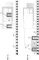
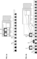
- FIGS. 1a and 1b illustrate an example of an existing type of alignment machine.
- the alignment machine is transported in a large truck.
- the alignment machine comprises a frame 300, which is moved by a lifting arm 400.
- a respective gripping and actuating element 10', 20' At each end of the frame 300 is fixed a respective gripping and actuating element 10', 20', each being adapted to be fixed to and actuate one of the two rails to be aligned 100, 200.
- Such an alignment machine has the disadvantages mentioned above.
- An aim of the invention is to propose an automatic rail alignment assembly which is lighter and more compact than the alignment assemblies known from the prior art.
- the first alignment system 10 comprises a first actuation system 51, 52 adapted to automatically adjust a position of the first rail 100 as a function of a position measured by the acquisition system 30.
- the second alignment system 20 comprises a second actuation system 51, 52 adapted to automatically adjust a position of the second rail 200 as a function of a position measured by the acquisition system 30.
- the alignment systems 10, 20 may be set up on, for example removably attached to, placed on, or wedged onto, track elements 70. Consequently, it is the track elements 70 that make it possible to set up the alignment systems 10, 20 relative to each other, thereby providing a common reference for positioning the two rails 100, 200 relative to each other.
- the positions of the alignment systems 10, 20 relative to each other are therefore fixed, without the alignment assembly requiring a rigid frame on which the two alignment systems 10, 20 would be fixed.
- the alignment of the rails 100, 200 is carried out automatically by the actuation systems 51, 52, as a function of a position measured by the acquisition system 30.
- the actuation system 51, 52 thus automatically actuates the corresponding rail 100, 200 in order to carry out its alignment.
- the alignment assembly can do without the presence of the lifting arm.
- the alignment assembly can therefore be transported on board a smaller vehicle than existing alignment assemblies. For example, it can be transported on board a van, or even loaded onto a lorry to be transported along the rails.
- the alignment assembly can further be unloaded and positioned around the rails 100, 200 to be aligned by an operator, due to its reduced weight.
- the transport constraints are reduced, which consequently increases the flexibility and reduces the cost of the rail alignment operation.
- a rail 100, 200 extends in a substantially longitudinal direction X, which corresponds to a main direction of the rail.
- a rail 100, 200 comprises a shoe, a head, and a web adapted to connect the shoe to the head.
- the head is opposite the shoe in a height direction Z of the rail which is substantially perpendicular to the longitudinal direction X.
- the head is located at a position higher than the foot of the rail 100, 200.
- a position in the height direction Z of the rail is called a pointed position.
- the rail 100, 200 may be substantially symmetrical with respect to a plane of symmetry of the rail extending substantially in the longitudinal direction X and in the height direction Z and passing through a center of the rail 100, 200.
- a transverse direction Y of the rail corresponds to a direction substantially perpendicular to the longitudinal direction X and the height direction Z of the rail, i.e. to the plane of symmetry of the rail.
- the shoe is adapted to be placed on and fixed to track elements 70, in particular to track sleepers 70, such that the sleepers 70 extend substantially in the transverse direction Y of the rail.
- a position in the transverse direction Y of the rail is called a track.
- An inclination of the rail 100, 200 about the longitudinal direction X of the rail is called inclination.
- Two rails 100, 200 are aligned when their point, their layout and their inclination are substantially identical. In other words, two rails 100, 200 are aligned when they have substantially the same inclination around the longitudinal direction X, the same layout in the transverse direction Y, and when their point in the height direction Z corresponds to the same determined objective point.
- Two aligned rails 100, 200 can be spaced apart in the longitudinal direction X by a certain distance. The space present between the two rails 100, 200 allows the two rails 100, 200 to be welded together subsequently.
- the position acquisition system 30 is adapted to measure a relative position of the first rail 100 and the second rail 200 relative to each other.
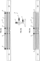
- the acquisition system 30 may comprise at least one rule 31 adapted to be positioned on each of the two rails 100, 200 to be aligned, as illustrated by way of non-limiting example in Figures 9a to 9c .
- Each rule 31 can be fixed to the two rails 100, 200 to be aligned.
- Each ruler 31 comprises at least one pair of sensors 35 adapted to measure a position of a rail 100, 200.
- a first sensor of the pair of sensors 35 is positioned at the first rail 100 and measures a position of the first rail 100
- a second sensor of the pair of sensors 35 is positioned at the second rail 200 and measures a position of the second rail 200.
- Each ruler 31 can be adapted to measure the sharpness and/or the layout and/or the inclination of each of the two rails 100, 200 to be aligned.
- the sharp point can in particular be measured at a determined longitudinal distance from a position of the weld of the rails 100, 200, and correspond to a distance in the height direction Z between the top of the head of the rail 100, 200 and the ruler 31 for measuring the sharp point of the rail 100, 200.
- the sharp point can be of the order of a few millimeters.
- the position acquisition system 30 may include three rules 31.
- the figure 9b thus illustrates a non-limiting example of a first rail 100, on which three rules 31 of the position acquisition system 30 are positioned.
- a first rule is adapted to measure the point
- a second rule is adapted to measure the layout
- a third rule is adapted to measure the inclination of the first rail 100 to be aligned.
- the alignment of the rails 100, 200 according to the position measured by a rule 31 can be carried out when the positions measured by the first and second sensors of the same pair of sensors 35 of said rule 31 are identical. More particularly, the alignment of the rails 100, 200 respectively in layout and inclination can be carried out when respectively the layout and the inclination measured by all the pairs of sensors of the respective rulers for measuring the layout and the inclination 31, is identical.
- the alignment of the rails 100, 200 in sharp can be carried out when the positions measured by the sensor couples of the rule 31 adapted to measure the sharp correspond to a sharp objective, which can be chosen by the welder.
- the sharp objective can be 1.5 mm.
- Each rule 31 placed on two rails 100, 200 to be aligned can comprise two pairs of sensors 35, the acquisition system 30 therefore comprising twelve sensors 35, as illustrated by way of non-limiting example in Figure 9a . Alignment according to the position measured by the ruler 31 is achieved when the four sensors 35 of the ruler 31 measure an identical position.
- each rule 31 placed on two rails 100, 200 to be aligned can comprise a single pair of sensors 35, the acquisition system 30 comprising six sensors 35, as illustrated by way of non-limiting example in figure 9c .
- This variant has the advantage of simplifying the system, by reducing the number of sensors.
- Each rule 31 then also includes two pads 36 of fixed thickness. A zeroing of the rule 31 is necessary to take into account the height of the pads 36.
- FIGS. 3a to 3d , 4a , 4b , 6a and 6b illustrate by way of non-limiting example a first rail alignment system 10 arranged at a first rail 100. It is understood that the second alignment system 20 may be substantially identical to the first alignment system 10. In the remainder of the application, any description made in relation to the first alignment system 10 may apply in the same way to the second alignment system 20.
- the first alignment system 10 is adapted to extend at a first rail 100, so as to adjust the position of the first rail 100. More particularly, the first alignment system 10 may be adapted to extend on either side of the first rail 100, i.e. on one side and the other of the first rail 100 in the transverse direction Y. Similarly, the second alignment system 20 may be adapted to extend on either side of the second rail 200 in the transverse direction Y.
- Each alignment system 10, 20 may have a respective plane of symmetry corresponding substantially to the plane of symmetry of the rail 100, 200 at which the alignment system 10, 20 is arranged and the position of which is to be adjusted.
- the plane of symmetry of the first alignment system 10 may correspond to the plane of symmetry of the first rail 100
- the plane of symmetry of the second alignment system 20 may correspond to the plane of symmetry of the second rail 200.
- Each actuation system 51, 52 may comprise at least one pair of actuation cylinders 51, 52 comprising two cylinders. Each cylinder of the pair of actuation cylinders 51, 52 is adapted to extend on a respective side of the rail 100, 200 whose position is to be adjusted, and to move said rail 100, 200 for the purpose of its alignment.
- each pair of actuating cylinders 51, 52 are arranged on either side of the rail 100, 200 in the transverse direction Y.
- each cylinder of the pair of actuating cylinders 51, 52 is capable of coming into contact with the rail 100, 200 on either side thereof, so as to form a rail clamp 100, 200.
- Each actuation system 51, 52 may comprise a pair of translation actuation cylinders 51 adapted to move the rail 100, 200 whose position is to be adjusted in translation along the transverse direction Y of the rail and/or along the height direction Z of the rail.
- Each of the two cylinders of the pair of translational actuating cylinders 51 can be adapted to be positioned in contact with a rail head 100, 200 on a respective side of said head.
- each of the two translational actuation cylinders may be mounted on a structural element 53, 54 of the alignment system 10, 20 and be adapted to extend from the structural element 53, 54 of the alignment system 10, 20 towards a corresponding rail head 100, 200, such that actuation of the translational actuation cylinders results in the application of a force to the corresponding rail head 100, 200.
- each of the two translational actuating cylinders may comprise a first end mounted on the structural element 53, 54 of the actuating system 51, 52 and a second end opposite the first end.
- the second end is adapted to come into contact with the rail head 100, 200, in particular into contact with a lower surface of the head, the rail head 100, 200 then resting substantially on the two cylinders.
- Each cylinder may be adapted to extend substantially diagonally both in a transverse direction Y and in a height direction Z of the rail.
- a similar and joint actuation of the two cylinders can make it possible to adjust a point of the rail 100, 200, that is to say to actuate the rail 100, 200 in translation in the height direction Z.
- An opposite and joint actuation of the two cylinders can make it possible to adjust a track of the rail 100, 200, that is to say to actuate the rail 100, 200 in translation in the transverse direction Y.
- a simultaneous and equivalent increase in the stroke of each of the two jacks makes it possible to push the head of the rail 100, 200 upwards, and thus to lift the rail 100, 200 relative to the track in the height direction Z of the rail, i.e. to increase the sharpness of the rail 100, 200.
- a simultaneous and equivalent decrease in the stroke of each of the two jacks causes the rail 100, 200 to move downwards under the effect of gravity, reducing the sharpness of the rail 100, 200.
- a greater deployment of one of the two cylinders relative to the other allows the rail 100, 200 to be moved in the transverse direction Y on the side opposite the most deployed cylinder.
- an increase in the stroke of a single cylinder which may be combined with a corresponding decrease in the stroke of the other cylinder, allows the head of the rail 100, 200 to be pushed to one side or the other in the transverse direction Y of the rail, thereby changing the path of the rail 100, 200.
- Each actuation system 51, 52 may comprise a pair of rotational actuation cylinders 52 adapted to vary an inclination of said rail 100, 200 around the longitudinal direction X of the rail.
- Each of the two cylinders of the pair of rotational actuating cylinders 52 can be adapted to be positioned in contact with a foot of the rail 100, 200 or the web of the rail 100, 200, on a respective side of said foot or said web.
- each of the two rotational actuation cylinders may be mounted on a structural element 53, 54 of the alignment system 10, 20 and be adapted to extend from the structural element 53, 54 of the alignment system 10, 20 towards a foot of the corresponding rail 100, 200 or towards the web of the corresponding rail 100, 200, such that an actuation of the rotational actuation cylinders results in the application of a force to the foot or to the web of the corresponding rail 100, 200.
- each of the two rotational actuating cylinders may comprise a first end mounted on the structural element 53, 54 of the actuating system 51, 52 and a second end opposite the first end.
- the second end is adapted to come into contact with the foot or the web of the rail 100, 200, in particular can be adapted to come into contact with an upper surface of the foot when an alignment of the rail 100, 200 in inclination must be carried out.
- Each jack can be adapted to extend substantially diagonally in both a transverse direction Y and a height direction Z of the rail.
- Actuation of just one of the two cylinders can make it possible to adjust an inclination of the rail 100, 200 relative to the longitudinal direction X.
- Such an actuation system 51, 52 comprising a pair of translation actuation cylinders 51 and a pair of rotation actuation cylinders 52 makes it possible to simply adjust the alignment of the rail 100, 200 in terms of sharpness in layout and in inclination. The number of parts is reduced, and the alignment kinematics is simple.
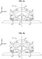
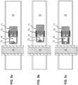
- the Figure 3a illustrates a first actuation system 51, 52 arranged around the first rail 100 and placed on track sleepers 70.
- the first actuation system 51, 52 comprises a pair of translational actuation cylinders 51 and a pair of rotational actuation cylinders 52.
- the two cylinders of the pair of actuation cylinders 51, 52 are retracted, so that the first rail 100 is not lifted, the first rail 100 being placed on the track sleepers 70.
- the first rail 100 is in a nominal position, that is to say has a nominal height, a nominal transverse position and a zero inclination.
- FIG 3b illustrates an example of a first rail 100 whose position in the height direction Z is modified relative to its nominal position by the two translational actuating cylinders of the first actuating system 51, 52.
- the two cylinders of the pair of actuating cylinders 51, 52 are deployed, so that the first rail 100 is lifted relative to the track, its point being modified.
- the transverse position shown in figure 3b substantially corresponds to the nominal transverse position of the first rail 100, and the inclination of the first rail 100 is substantially zero.
- FIG 3c illustrates an example of a first rail 100 whose position in the transverse direction Y is modified relative to its nominal transverse position by the two translational actuating cylinders of the first actuating system 51, 52.
- One cylinder is more deployed than the other, so that the first rail 100 is moved to the side opposite the most deployed cylinder, its path being modified.
- the height of the first rail 100 shown in figure 3c corresponds approximately to the height of the first rail 100 shown in figure 3b , and the inclination of the first rail 100 is substantially zero.
- FIG. 3d figure illustrates an example of a first rail 100 whose inclination relative to the longitudinal direction X is modified relative to the zero inclination by the two translational actuation cylinders of the first actuation system 51, 52. Only one of the two cylinders is deployed, so as to adjust the inclination of the first rail 100 relative to the longitudinal direction X.
- the height of the first rail 100 shown in 3d figure corresponds approximately to the height of the first rail 100 illustrated in figure 3b
- the transverse position of the first rail 100 corresponds substantially to the nominal transverse position of the first rail 100.
- each alignment system 10, 20 comprises a single structural element 53 in the form of a rigid frame adapted to extend on either side of the rail 100, 200 whose position is to be adjusted.
- Each cylinder of the at least one pair of actuating cylinders 51, 52 is mounted on the single structural element 53.
- the alignment assembly of this first embodiment has a reduced number of parts.
- the rigid frame 53 may have a substantially semi-circular shape, and be adapted to be centered on the rail 100, 200 around which the alignment system 10, 20 is aligned.
- the cylinders of the pair of translational actuation cylinders 51 and/or of the pair of rotational actuation cylinders 52 may be mounted on a lower part of each end of the semi-circle of the rigid frame 53.
- each alignment system 10, 20 comprises two separate structural elements 54.
- Each structural element 54 is adapted to extend on a respective side of the rail 100, 200 whose position is to be adjusted.
- Each cylinder of the at least one pair of actuating cylinders 51, 52 is mounted on a respective structural element 54.
- the alignment assembly of this second embodiment has a further reduced weight and size.
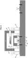
- FIG. 8 Another embodiment of an assembly for automatic rail alignment is illustrated by way of non-limiting example in figure 8 .
- the assembly for automatic rail alignment comprises an actuation system 51, 52 comprising a pair of actuation cylinders 55 and an additional actuation cylinder 57.
- the pair of actuating cylinders 55 comprises two actuating cylinders 55 arranged on either side of the rail 100, 200 in the transverse direction Y.
- the pair of actuating cylinders 55 is adapted to modify a position of the rail 100, 200 both in translation in a height direction Z to align the rail 100, 200 in a pointed position, and in rotation about the longitudinal axis to align the rail 100, 200 in an inclination.
- translation in the height direction Z is guided by slides 56 arranged on either side of the rail 100, 200 and extending substantially in the height direction Z of the rail.
- An identical modification of the height of the two jacks 55 results in a modification of the height of the rail 100, 200.
- a different modification of the height of the two jacks 55 results in a modification of the inclination of the rail 100, 200.
- the additional actuating cylinder 57 is adapted to be arranged substantially above the rail 100, 200.
- the additional actuating cylinder 57 is adapted to modify a position of the rail 100, 200 in translation in the transverse direction Y of the rail to align the rail 100, 200 in layout.
- the translation in the transverse direction Y is guided by a slide 58 adapted to extend substantially above the rail 100, 200, in the transverse direction Y of the rail.
- the assembly for automatic rail alignment further comprises two clamping cylinders 59 arranged on either side of the rail 100, 200 and adapted to grip the rail 100, 200 via a jaw 80 arranged on either side and in contact with the rail 100, 200.
- the actuation of the actuation cylinders 55, 57 causes the application of a force to the rail 100, 200 by means of the torque of clamping cylinders 59.
- the first alignment system 10 is adapted to be placed on, or wedged on, the first track element 70
- the second alignment system 20 is adapted to be placed on, or wedged on, the second track element 70.
- the weight of the rails 100, 200 makes it possible to maintain the alignment systems 10, 20 in place relative to the track elements 70, in particular makes it possible to block the alignment systems 10, 20 in the transverse direction Y.
- This first example of embodiment can in particular be used in the case of a straight line track, that is to say when few radial forces are likely to be exerted on the alignment systems 10, 20.
- the alignment systems 10, 20 may be adapted to be placed on, or wedged onto, the respective sleepers 70, on either side of the respective rails 100, 200.
- the first alignment system 10 is adapted to be removably attached to the first track element 70
- the second alignment system 20 is adapted to be removably attached to the second track element 70.
- each alignment system 10, 20 may comprise at least one hook 60 adapted to be removably attached to at least one corresponding hook of the track element 70.
- This second example of embodiment can in particular be used in the case of a curved track, that is to say when significant radial forces are likely to be exerted on the alignment systems 10, 20.
- the hook 60 can be adapted to be arranged in a lower part of a structural element 53, 54 of the alignment system 10, 20.
- Each alignment system 10, 20 may comprise two hooks 60 adapted to extend on either side of the rail 100, 200 at which the alignment system 10, 20 is located, in a substantially symmetrical manner relative to the plane of symmetry of the rail, opposite two corresponding hooks of the track element 70.
- the alignment system 10, 20 is fixed to the track element 70 by means of two hooks 60.
- the at least one hook 60 of the alignment system 10, 20 may comprise a plate 71 adapted to be fixed to a corresponding hook of the track element 70.
- Said plate 71 may comprise several different fixing means adapted to ensure fixing of the plate 71 to several different types of hooks of the track element 70.
- the alignment system 10, 20 can be fixed to track elements 70 having hooks of different types.
- the alignment assembly therefore has a high modularity, and can adapt to different types of tracks.
- the track element 70 may be a track sleeper.
- the track sleeper 70 may have different types of attachment, for example a lag screw type attachment, a threaded rod type attachment, or a clip type attachment.
- the adjustment plate 71 of the alignment system 10, 20 thus allows attachment to a track sleeper 70 comprising a lag screw, threaded rod or clip type hook.
- the alignment system 10, 20 can therefore be attached to a majority of existing track sleepers 70.
- the first fixing means and/or the second fixing means of the plate 71 are arranged in contact with the corresponding attachment of the track sleeper 70.
- the plate 71 may be able to be turned over to place the desired fixing means in contact with the track sleeper 70.
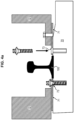
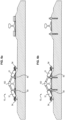
- the Figures 4a , 4b , 5a, 5b , 6b And 7b represent by way of non-limiting example a fixing of the plate 71 to a lag screw type or threaded rod type hook of the track sleeper 70.
- the first means for fixing the plate 71 may comprise a through hole 73 adapted to extend opposite a corresponding hole drilled in the track sleeper 70.
- the through hole 73 may have shapes and dimensions adapted to extend around a threaded rod of the track sleeper 70, and/or to receive a lag screw.
- the Figures 5c , 6a And 7a represent as non-limiting examples a fixing of the plate 71 to a clip-type hook of the track sleeper 70.
- the second means for fixing the plate 71 may comprise a through-hole 74 adapted to extend around a clip of the track sleeper 70.
- the hole 74 of the plate 71 may be substantially rectangular, as illustrated in FIG. Figures 5c , 6a And 7a .
- the second means for fixing the plate 71 may comprise a tab adapted to be placed in contact with the rail 100, 200 when the plate 71 is placed on the track sleeper 70.
- the tab comprises fixing means adapted to fix the tab to the rail 100, 200.
- the tab may be rotatably hinged relative to the plate 71 by means of a hinge, such that once the plate 71 is placed on the track sleeper 70, the tab may be actuated in rotation to come into contact with the corresponding rail 100, 200.
- the tab may have clipping means adapted to clip the tab to the rail 100, 200 once the tab is in contact with the rail 100, 200.
- a distance along the transverse direction Y from the track sleeper hook 70 to the rail 100, 200, i.e. a center distance of the track sleeper hook 70, is likely to vary depending on the type of track sleeper 70.
- the adjustment plate 71 may comprise a center distance adjustment means 75 making it possible to adapt to different transverse distances from the track sleeper hook 70 to the rail 100, 200.
- the center distance adjustment means 75 may be arranged near the third plate fixing means 71.
- the center distance adjustment means 75 may consist of at least one, for example two, center distance adjustment screws.
- FIGS. 5a and 5b illustrate by way of non-limiting example two examples of adjustment plate 71 of an alignment system 10, 20 placed on two crossbar hooks of track 70 of the lag screw type or of the threaded rod type having different center distances using two center distance adjustment screws 75.
- the track sleeper hook 70 of the Figure 5a is arranged closer to the rail 100, 200, that is to say has a smaller center distance, than the track sleeper hook 70 of the Figure 5b .
- the alignment assembly may comprise a control system adapted to control an actuation of the actuation systems 51, 52 of the alignment assembly as a function of a position measured by the acquisition system 30.
- the control system may comprise a control unit adapted to provide an actuation command for the actuation systems 51, 52 of the alignment assembly as a function of a position measured by the acquisition system 30.
- the control unit comprises a processor adapted to calculate, from the position measured by the acquisition system 30, an actuation command for the actuation systems 51, 52, more particularly for each cylinder of the alignment assembly, with a view to aligning the rails 100, 200.
- the control system may include a hydraulic power unit, an electric motor, or a battery, adapted to move one or more cylinders.
- the control system may be adapted to be unloaded onto the track with the remainder of the alignment assembly, or be adapted to remain in a system for transporting the alignment assembly onto the track.
- the method described makes it possible to align the rails 100, 200 automatically and using a device having reduced weight and size.
- the step of acquiring a position may be preceded by a step of setting up the position acquisition system 30, in particular each of the rules 31 of the acquisition system 30, on the two rails 100, 200.
- the alignment of the rails 100, 200 may be followed by a step of welding the rails 100, 200, for example by aluminothermic welding.
Landscapes
- Engineering & Computer Science (AREA)
- Physics & Mathematics (AREA)
- Optics & Photonics (AREA)
- Mechanical Engineering (AREA)
- Architecture (AREA)
- Civil Engineering (AREA)
- Structural Engineering (AREA)
- Machines For Laying And Maintaining Railways (AREA)
- Automatic Assembly (AREA)
- Automobile Manufacture Line, Endless Track Vehicle, Trailer (AREA)
Claims (12)
- Anordnung zum automatischen Ausrichten von Schienen, umfassend:- ein erstes Ausrichtungssystem (10), das geeignet ist, auf einem ersten Gleiselement (70) im Bereich einer ersten Schiene (100) platziert zu sein;- ein zweites Ausrichtungssystem (20), das geeignet ist, auf einem zweiten Gleiselement (70) im Bereich einer zweiten Schiene (200) platziert zu sein;dadurch gekennzeichnet, dass die Anordnung ferner umfasst- ein Positionserfassungssystem (30), das mindestens einen Positionssensor für die erste Schiene (100) und/oder für die zweite Schiene (200) umfasst, wobei das erste Ausrichtungssystem (10) ein erstes Betätigungssystem (51, 52) umfasst, das geeignet ist, eine Position der ersten Schiene (100) in Abhängigkeit von einer von dem Erfassungssystem (30) gemessenen Position automatisch einzustellen, und/oder das zweite Ausrichtungssystem (20) ein zweites Betätigungssystem (51, 52) umfasst, das geeignet ist, eine Position der zweiten Schiene (200) in Abhängigkeit von einer von dem Erfassungssystem (30) gemessenen Position automatisch einzustellen.
- Anordnung zum automatischen Ausrichten von Schienen nach Anspruch 1, wobei das Positionserfassungssystem (30) geeignet ist, eine relative Position der ersten Schiene (100) und der zweiten Schiene (200) zueinander zu messen.
- Anordnung zum automatischen Ausrichten von Schienen nach Anspruch 1 oder Anspruch 2, wobei jedes Betätigungssystem (51, 52) mindestens ein Paar Betätigungszylinder (51, 52) mit zwei Zylindern umfasst, wobei jeder Zylinder des Paars Betätigungszylinder (51, 52) geeignet ist, sich auf einer jeweiligen Seite der Schiene (100, 200), deren Position einzustellen ist, zu erstrecken und die Schiene (100, 200) zwecks ihrer Ausrichtung zu verlagern.
- Anordnung zum automatischen Ausrichten von Schienen nach Anspruch 3, wobei jedes Betätigungssystem (51, 52) ein Paar Translationsbetätigungszylinder (51) umfasst, das geeignet ist, die Schiene (100, 200) translatorisch entlang einer Schienenquerrichtung (Y) und/oder entlang einer Schienenhöhenrichtung (Z) zu verlagern.
- Anordnung zum automatischen Ausrichten von Schienen nach Anspruch 4, wobei jeder der beiden Zylinder des Paars Translationsbetätigungszylinder (51) geeignet ist, in Kontakt mit einem Schienenkopf der Schiene (100, 200) auf einer jeweiligen Seite des Schienenkopfes (100, 200) positioniert zu sein.
- Anordnung zum automatischen Ausrichten von Schienen nach einem der Ansprüche 3 bis 5, wobei jedes Betätigungssystem (51, 52) ein Paar Drehbetätigungszylinder (52) umfasst, das geeignet ist, eine Neigung der Schiene (100, 200) um eine Schienenlängsrichtung (X) zu ändern.
- Anordnung zum automatischen Ausrichten von Schienen nach einem der Ansprüche 3 bis 6, wobei jedes Ausrichtungssystem (10, 20) ein einzelnes Strukturelement (53) in Form eines starren Rahmens umfasst, der geeignet ist, sich auf beiden Seiten der Schiene (100, 200) zu erstrecken, deren Position einzustellen ist, wobei jeder Zylinder des mindestens einen Paars Betätigungszylinder (51, 52) auf dem einzelnen Strukturelement (53) angebracht ist.
- Anordnung zum automatischen Ausrichten von Schienen nach einem der Ansprüche 3 bis 6, wobei jedes Ausrichtungssystem (10, 20) zwei verschiedene Strukturelemente (54) umfasst, wobei jedes Strukturelement (54) geeignet ist, sich auf einer jeweiligen Seite der Schiene (100, 200) zu erstrecken, deren Position einzustellen ist, wobei jeder Zylinder des mindestens einen Paars Betätigungszylinder (51, 52) auf einem jeweiligen Strukturelement (54) angebracht ist.
- Anordnung zum automatischen Ausrichten von Schienen nach einem der vorhergehenden Ansprüche, wobei jedes Ausrichtungssystem (10, 20) mindestens eine Aufhängung (60) umfasst, der geeignet ist, lösbar an mindestens einer entsprechenden Aufhängung des Schienenelements (70) befestigt zu sein.
- Anordnung zum automatischen Ausrichten von Schienen nach Anspruch 9, wobei die mindestens eine Aufhängung (60) des Ausrichtungssystems (10, 20) eine Platte (71) umfasst, die geeignet ist, an einer entsprechenden Aufhängung des Gleiselements (70) befestigt zu sein, wobei die Platte (71) in Abhängigkeit von einem Typ der Aufhängung des Gleiselements (70) regulierbar ist.
- Anordnung zum automatischen Ausrichten von Schienen nach Anspruch 10, wobei das Gleiselement (70) eine Gleisschwelle ist, und wobei die Platte (71) umfasst:- erste Mittel zur Befestigung an einer Aufhängung vom Typ Schwellenschraube oder Gewindestange der Gleisschwelle (70),- zweite Mittel zur Befestigung an einer Aufhängung vom Typ Clip der Gleisschwelle (70), und- dritte Mittel zur Befestigung am Ausrichtungssystem (10, 20).
- Verfahren zum automatischen Ausrichten von Schienen mit Hilfe einer Anordnung zum automatischen Ausrichten von Schienen nach einem der vorhergehenden Ansprüche, das die folgenden Schritte umfasst:- Platzieren des ersten Ausrichtungssystems (10) auf dem ersten Gleiselement (70);- Platzieren des zweiten Ausrichtungssystems (20) auf dem zweiten Gleiselement (70);dadurch gekennzeichnet, dass das Verfahren ferner die folgenden Schritte umfasst:- Erfassen einer Position der ersten Schiene (100) und/oder der zweiten Schiene (200) mittels des Positionserfassungssystems (30);- automatisches Einstellen einer Position der ersten Schiene (100) und/oder der zweiten Schiene (200) mittels des ersten Betätigungssystems (51, 52) und/oder des zweiten Betätigungssystems (51, 52), so dass die erste Schiene (100) und die zweite Schiene (200) ausgerichtet werden.
Applications Claiming Priority (2)
| Application Number | Priority Date | Filing Date | Title |
|---|---|---|---|
| FR2100487A FR3118970B1 (fr) | 2021-01-19 | 2021-01-19 | Ensemble pour l’alignement automatique de rails |
| PCT/FR2022/050098 WO2022157449A1 (fr) | 2021-01-19 | 2022-01-18 | Ensemble et procédé d'alignement automatique de rails |
Publications (3)
| Publication Number | Publication Date |
|---|---|
| EP4281618A1 EP4281618A1 (de) | 2023-11-29 |
| EP4281618B1 true EP4281618B1 (de) | 2024-10-16 |
| EP4281618C0 EP4281618C0 (de) | 2024-10-16 |
Family
ID=74669161
Family Applications (1)
| Application Number | Title | Priority Date | Filing Date |
|---|---|---|---|
| EP22705422.8A Active EP4281618B1 (de) | 2021-01-19 | 2022-01-18 | Anordnung und verfahren zum automatischen ausrichten von schienen |
Country Status (6)
| Country | Link |
|---|---|
| US (1) | US20240084519A1 (de) |
| EP (1) | EP4281618B1 (de) |
| CN (1) | CN116997696B (de) |
| AU (1) | AU2022210499A1 (de) |
| FR (1) | FR3118970B1 (de) |
| WO (1) | WO2022157449A1 (de) |
Citations (3)
| Publication number | Priority date | Publication date | Assignee | Title |
|---|---|---|---|---|
| EP0253634A2 (de) | 1986-07-14 | 1988-01-20 | H.A. Schlatter Ag | Schienen-Schweissgerät |
| US6762390B2 (en) | 2002-01-28 | 2004-07-13 | Franz Plasser Bahnbaumaschinen-Industriegesellschaft M.B.H. | Rail welding device |
| WO2020058208A1 (fr) | 2018-09-17 | 2020-03-26 | Mornac Jean Pierre | Systeme d'alignement de portions de rail pour soudeuse a induction |
Family Cites Families (8)
| Publication number | Priority date | Publication date | Assignee | Title |
|---|---|---|---|---|
| EP0119098A3 (de) | 1983-03-14 | 1984-10-24 | A.I. Welders Limited | Verfahren und Apparat zum Ausrichten zweier Werkstücke |
| CA1261363A (en) * | 1986-03-05 | 1989-09-26 | Masaharu Sekino | Method of clamping rails for pressure welding the same clamping apparatus therefore |
| CN100501001C (zh) * | 2006-03-30 | 2009-06-17 | 中铁八局集团有限公司 | 双块式无碴轨道轨排精确调整施工方法 |
| ES2326403B2 (es) * | 2009-03-27 | 2010-04-07 | Tecsa Empresa Constructora, S.A. | Maquina de posicionamiento y escuadrado de traviesas de vias de ferrocarril. |
| US8684279B1 (en) * | 2011-10-13 | 2014-04-01 | Jessie L. Bledsoe | Railroad alignment system |
| CN102493295B (zh) | 2011-12-10 | 2014-04-30 | 昆明中铁大型养路机械集团有限公司 | 拉轨对正装置 |
| FR2998310B1 (fr) * | 2012-11-16 | 2015-02-06 | Anciens Etablissements Lucien Geismar Soc D | Ensemble pour un dispositif de serrage d’un tendeur de rail |
| GB2551394B (en) * | 2016-06-17 | 2020-09-09 | Mirage Ltd | Railway rail induction-welding device |
-
2021
- 2021-01-19 FR FR2100487A patent/FR3118970B1/fr active Active
-
2022
- 2022-01-18 WO PCT/FR2022/050098 patent/WO2022157449A1/fr not_active Ceased
- 2022-01-18 AU AU2022210499A patent/AU2022210499A1/en active Pending
- 2022-01-18 CN CN202280022681.4A patent/CN116997696B/zh active Active
- 2022-01-18 EP EP22705422.8A patent/EP4281618B1/de active Active
- 2022-01-18 US US18/272,871 patent/US20240084519A1/en active Pending
Patent Citations (3)
| Publication number | Priority date | Publication date | Assignee | Title |
|---|---|---|---|---|
| EP0253634A2 (de) | 1986-07-14 | 1988-01-20 | H.A. Schlatter Ag | Schienen-Schweissgerät |
| US6762390B2 (en) | 2002-01-28 | 2004-07-13 | Franz Plasser Bahnbaumaschinen-Industriegesellschaft M.B.H. | Rail welding device |
| WO2020058208A1 (fr) | 2018-09-17 | 2020-03-26 | Mornac Jean Pierre | Systeme d'alignement de portions de rail pour soudeuse a induction |
Non-Patent Citations (1)
| Title |
|---|
| ANONYMOUS: " Deliverable D2.2 - Prototype device for joint alignment, additional forging and enhanced cooling, with performance specifications and concept drawings", WRIST - GRANT AGREEMENT 636164 - INNOVATIVE WELDING PROCESSES FOR NEW RAIL INFRASTRUCTURES, 30 August 2016 (2016-08-30), XP093295397, Retrieved from the Internet <URL:https://cordis.europa.eu/project/id/636164/results> |
Also Published As
| Publication number | Publication date |
|---|---|
| WO2022157449A1 (fr) | 2022-07-28 |
| US20240084519A1 (en) | 2024-03-14 |
| CN116997696B (zh) | 2026-01-09 |
| FR3118970A1 (fr) | 2022-07-22 |
| EP4281618C0 (de) | 2024-10-16 |
| AU2022210499A1 (en) | 2023-08-10 |
| FR3118970B1 (fr) | 2023-01-06 |
| AU2022210499A9 (en) | 2024-05-16 |
| CN116997696A (zh) | 2023-11-03 |
| EP4281618A1 (de) | 2023-11-29 |
Similar Documents
| Publication | Publication Date | Title |
|---|---|---|
| EP0233098B1 (de) | Verladevorrichtung zum Laden, insbesondere zum schnellen Transferieren von palettierten Lasten | |
| EP3647208B1 (de) | Transportwagen | |
| FR2490168A1 (fr) | Dispositif pour bancs de mesure et d'extension de carrosseries de vehicules | |
| EP0311535A1 (de) | Richtbank für die Montage, Überwachung und Reparatur, insbesondere von Karrosserien von Kraftfahrzeugen | |
| EP4281618B1 (de) | Anordnung und verfahren zum automatischen ausrichten von schienen | |
| FR3008065A1 (fr) | Dispositif desassembleur pour vehicule de type tracteur agricole ou similaire | |
| EP0100926B1 (de) | Fahrzeug zur Handhabung von Materialien mit orientierbarem Ausleger und eingebautem Stabilisiergestell | |
| EP3141517B1 (de) | Schnellmontage-kran ohne ballastierung | |
| EP3070203B1 (de) | Be-, entlade- und aufsetzsystem einer schienenweiche auf ein bahngleis | |
| EP1418151B1 (de) | Gestell mit Gelenkvorrichtungen für Stützarme | |
| EP2494861B1 (de) | Gestell einer Sämaschine, das eine Transport- und eine Arbeitsposition einnehmen kann, wobei es eine starre oder flexible Konfiguration zulässt | |
| WO2013038080A1 (fr) | Dispositif d'assemblage de moteur et procédé d'assemblage et de contrôle d'un tel dispositif d'assemblage | |
| FR3049252A1 (fr) | Bogie comprenant une liaison rigide entre les boites d'essieu, et vehicule ferroviaire associe | |
| EP3889094B1 (de) | Kran mit automatisierter montage, der ein abnehmbares ballastelement für den transport auf einem sattel umfasst | |
| EP0065434B1 (de) | Eisenbahneinheit zum Fördern und Verlagern von sperrigen Lasten | |
| BE1012315A6 (fr) | Support porte-bagages a reglages multiples pour vehicules. | |
| FR2671299A1 (fr) | Structure pour supporter les outils de formage dans une machine a former les toles par etirage. | |
| FR3022626A1 (fr) | Systeme de mesure de charge d'un vehicule ferroviaire, voie ferroviaire equipee d'un tel systeme et procede de mesure de charge d'un vehicule ferroviaire | |
| FR2553731A1 (fr) | Dispositif pour le transport par etapes de charges lourdes | |
| FR3013339A1 (fr) | Agres de stockage, de manutention et de transport de plaques de grandes dimensions et vehicule l'incorporant | |
| FR2724159A1 (fr) | Pont elevateur pour vehicules a prise sous chassis et a prise sous roues | |
| EP3252002B1 (de) | Spannsystem für die karosserie eines fahrzeugs auf einem hubtisch | |
| FR2700514A1 (fr) | Engin de manutention ferroviaire. | |
| FR3153413A1 (fr) | Dispositif pour le contrôle technique et/ou la réparation et/ou l’entretien d’engin roulant à deux ou trois roues | |
| EP4186811A1 (de) | Device for handling a railway vehicle coupling and associated method |
Legal Events
| Date | Code | Title | Description |
|---|---|---|---|
| STAA | Information on the status of an ep patent application or granted ep patent |
Free format text: STATUS: UNKNOWN |
|
| STAA | Information on the status of an ep patent application or granted ep patent |
Free format text: STATUS: THE INTERNATIONAL PUBLICATION HAS BEEN MADE |
|
| PUAI | Public reference made under article 153(3) epc to a published international application that has entered the european phase |
Free format text: ORIGINAL CODE: 0009012 |
|
| STAA | Information on the status of an ep patent application or granted ep patent |
Free format text: STATUS: REQUEST FOR EXAMINATION WAS MADE |
|
| 17P | Request for examination filed |
Effective date: 20230817 |
|
| AK | Designated contracting states |
Kind code of ref document: A1 Designated state(s): AL AT BE BG CH CY CZ DE DK EE ES FI FR GB GR HR HU IE IS IT LI LT LU LV MC MK MT NL NO PL PT RO RS SE SI SK SM TR |
|
| DAV | Request for validation of the european patent (deleted) | ||
| DAX | Request for extension of the european patent (deleted) | ||
| GRAP | Despatch of communication of intention to grant a patent |
Free format text: ORIGINAL CODE: EPIDOSNIGR1 |
|
| STAA | Information on the status of an ep patent application or granted ep patent |
Free format text: STATUS: GRANT OF PATENT IS INTENDED |
|
| RIN1 | Information on inventor provided before grant (corrected) |
Inventor name: ERRABIE, IMAD Inventor name: DEMOND, NICOLAS |
|
| INTG | Intention to grant announced |
Effective date: 20240510 |
|
| GRAS | Grant fee paid |
Free format text: ORIGINAL CODE: EPIDOSNIGR3 |
|
| GRAA | (expected) grant |
Free format text: ORIGINAL CODE: 0009210 |
|
| STAA | Information on the status of an ep patent application or granted ep patent |
Free format text: STATUS: THE PATENT HAS BEEN GRANTED |
|
| AK | Designated contracting states |
Kind code of ref document: B1 Designated state(s): AL AT BE BG CH CY CZ DE DK EE ES FI FR GB GR HR HU IE IS IT LI LT LU LV MC MK MT NL NO PL PT RO RS SE SI SK SM TR |
|
| REG | Reference to a national code |
Ref country code: GB Ref legal event code: FG4D Free format text: NOT ENGLISH |
|
| REG | Reference to a national code |
Ref country code: CH Ref legal event code: EP |
|
| REG | Reference to a national code |
Ref country code: IE Ref legal event code: FG4D Free format text: LANGUAGE OF EP DOCUMENT: FRENCH |
|
| REG | Reference to a national code |
Ref country code: DE Ref legal event code: R096 Ref document number: 602022006887 Country of ref document: DE |
|
| U01 | Request for unitary effect filed |
Effective date: 20241110 |
|
| U07 | Unitary effect registered |
Designated state(s): AT BE BG DE DK EE FI FR IT LT LU LV MT NL PT RO SE SI Effective date: 20241119 |
|
| U20 | Renewal fee for the european patent with unitary effect paid |
Year of fee payment: 4 Effective date: 20241224 |
|
| PG25 | Lapsed in a contracting state [announced via postgrant information from national office to epo] |
Ref country code: IS Free format text: LAPSE BECAUSE OF FAILURE TO SUBMIT A TRANSLATION OF THE DESCRIPTION OR TO PAY THE FEE WITHIN THE PRESCRIBED TIME-LIMIT Effective date: 20250216 Ref country code: HR Free format text: LAPSE BECAUSE OF FAILURE TO SUBMIT A TRANSLATION OF THE DESCRIPTION OR TO PAY THE FEE WITHIN THE PRESCRIBED TIME-LIMIT Effective date: 20241016 |
|
| PG25 | Lapsed in a contracting state [announced via postgrant information from national office to epo] |
Ref country code: ES Free format text: LAPSE BECAUSE OF FAILURE TO SUBMIT A TRANSLATION OF THE DESCRIPTION OR TO PAY THE FEE WITHIN THE PRESCRIBED TIME-LIMIT Effective date: 20241016 |
|
| PG25 | Lapsed in a contracting state [announced via postgrant information from national office to epo] |
Ref country code: NO Free format text: LAPSE BECAUSE OF FAILURE TO SUBMIT A TRANSLATION OF THE DESCRIPTION OR TO PAY THE FEE WITHIN THE PRESCRIBED TIME-LIMIT Effective date: 20250116 |
|
| PG25 | Lapsed in a contracting state [announced via postgrant information from national office to epo] |
Ref country code: GR Free format text: LAPSE BECAUSE OF FAILURE TO SUBMIT A TRANSLATION OF THE DESCRIPTION OR TO PAY THE FEE WITHIN THE PRESCRIBED TIME-LIMIT Effective date: 20250117 |
|
| PGFP | Annual fee paid to national office [announced via postgrant information from national office to epo] |
Ref country code: CH Payment date: 20250201 Year of fee payment: 4 |
|
| PG25 | Lapsed in a contracting state [announced via postgrant information from national office to epo] |
Ref country code: PL Free format text: LAPSE BECAUSE OF FAILURE TO SUBMIT A TRANSLATION OF THE DESCRIPTION OR TO PAY THE FEE WITHIN THE PRESCRIBED TIME-LIMIT Effective date: 20241016 |
|
| PG25 | Lapsed in a contracting state [announced via postgrant information from national office to epo] |
Ref country code: RS Free format text: LAPSE BECAUSE OF FAILURE TO SUBMIT A TRANSLATION OF THE DESCRIPTION OR TO PAY THE FEE WITHIN THE PRESCRIBED TIME-LIMIT Effective date: 20250116 |
|
| PG25 | Lapsed in a contracting state [announced via postgrant information from national office to epo] |
Ref country code: SM Free format text: LAPSE BECAUSE OF FAILURE TO SUBMIT A TRANSLATION OF THE DESCRIPTION OR TO PAY THE FEE WITHIN THE PRESCRIBED TIME-LIMIT Effective date: 20241016 |
|
| PLBI | Opposition filed |
Free format text: ORIGINAL CODE: 0009260 |
|
| PG25 | Lapsed in a contracting state [announced via postgrant information from national office to epo] |
Ref country code: SK Free format text: LAPSE BECAUSE OF FAILURE TO SUBMIT A TRANSLATION OF THE DESCRIPTION OR TO PAY THE FEE WITHIN THE PRESCRIBED TIME-LIMIT Effective date: 20241016 |
|
| PLAX | Notice of opposition and request to file observation + time limit sent |
Free format text: ORIGINAL CODE: EPIDOSNOBS2 |
|
| PG25 | Lapsed in a contracting state [announced via postgrant information from national office to epo] |
Ref country code: CZ Free format text: LAPSE BECAUSE OF FAILURE TO SUBMIT A TRANSLATION OF THE DESCRIPTION OR TO PAY THE FEE WITHIN THE PRESCRIBED TIME-LIMIT Effective date: 20241016 |
|
| 26 | Opposition filed |
Opponent name: GOLDSCHMIDT HOLDING GMBH Effective date: 20250711 |
|
| PG25 | Lapsed in a contracting state [announced via postgrant information from national office to epo] |
Ref country code: MC Free format text: LAPSE BECAUSE OF FAILURE TO SUBMIT A TRANSLATION OF THE DESCRIPTION OR TO PAY THE FEE WITHIN THE PRESCRIBED TIME-LIMIT Effective date: 20241016 |
|
| PLBB | Reply of patent proprietor to notice(s) of opposition received |
Free format text: ORIGINAL CODE: EPIDOSNOBS3 |
|
| U20 | Renewal fee for the european patent with unitary effect paid |
Year of fee payment: 5 Effective date: 20251211 |