EP4281302B1 - Luftausströmvorrichtung zur zuführung von temperierter luft für einen innenraum eines kraftfahrzeugs - Google Patents
Luftausströmvorrichtung zur zuführung von temperierter luft für einen innenraum eines kraftfahrzeugs Download PDFInfo
- Publication number
- EP4281302B1 EP4281302B1 EP21823206.4A EP21823206A EP4281302B1 EP 4281302 B1 EP4281302 B1 EP 4281302B1 EP 21823206 A EP21823206 A EP 21823206A EP 4281302 B1 EP4281302 B1 EP 4281302B1
- Authority
- EP
- European Patent Office
- Prior art keywords
- air outlet
- outlet device
- air
- slats
- pin
- Prior art date
- Legal status (The legal status is an assumption and is not a legal conclusion. Google has not performed a legal analysis and makes no representation as to the accuracy of the status listed.)
- Active
Links
Images
Classifications
-
- B—PERFORMING OPERATIONS; TRANSPORTING
- B60—VEHICLES IN GENERAL
- B60H—ARRANGEMENTS OF HEATING, COOLING, VENTILATING OR OTHER AIR-TREATING DEVICES SPECIALLY ADAPTED FOR PASSENGER OR GOODS SPACES OF VEHICLES
- B60H1/00—Heating, cooling or ventilating devices
- B60H1/34—Nozzles; Air-diffusers
- B60H1/3414—Nozzles; Air-diffusers with means for adjusting the air stream direction
- B60H1/3421—Nozzles; Air-diffusers with means for adjusting the air stream direction using only pivoting shutters
-
- B—PERFORMING OPERATIONS; TRANSPORTING
- B60—VEHICLES IN GENERAL
- B60H—ARRANGEMENTS OF HEATING, COOLING, VENTILATING OR OTHER AIR-TREATING DEVICES SPECIALLY ADAPTED FOR PASSENGER OR GOODS SPACES OF VEHICLES
- B60H1/00—Heating, cooling or ventilating devices
- B60H1/34—Nozzles; Air-diffusers
- B60H2001/3471—Details of actuators
Definitions
- the invention relates to an air outlet device for supplying tempered air for an interior of a motor vehicle according to the preamble of patent claim 1.
- Air outlet devices for the interior of motor vehicles are already known from the prior art. These are designed to allow tempered air to flow out for an occupant.
- slats can be designed within the air outlet opening, whereby a direction of air flow can be adjusted by an occupant.
- the DE 10 2015 000 874 A1 relates to an air vent for the passenger compartment of a motor vehicle.
- the air vent has a cylindrical tube-shaped louvre carrier with louvres pivotably mounted in it.
- the louvre carrier with the louvres can be driven in rotation using an electric motor drive.
- An axially movable adjusting ring on the louvre carrier enables the louvres to be pivoted in any rotational position of the louvre carrier.
- a control cam on a cylinder moves the adjusting ring axially using an adjusting slide.
- the cylinder is also driven by the electric motor drive, which can be switched to a gear for rotating the louvre carrier or the cylinder with control cam.
- the DE 20 2009 005 243 U1 shows a round nozzle for directing air flows, in particular in heating, air conditioning and ventilation systems in motor vehicles, at least comprising a housing with at least one cylindrical opening with air deflector discs attached thereto, an adjusting ring for adjusting the air deflector discs, which is rotatably mounted on the opening wall of the housing, characterized in that at least two air deflection discs are provided as air deflection means, which are fixed to an axis or a shaft or deflectable in the longitudinal direction of the axis or shaft, symmetrically or asymmetrically arranged so as to prevent rotation with respect to one another, wherein the air deflection discs have a contour such that by rotating the shaft about the longitudinal axis or by rotating the adjusting ring with the transversely inserted axis, the air deflection discs assume different deflection positions relative to the longitudinal axis of the axis or shaft and/or the housing and cause different flow deflections.
- HVAC heating, ventilation, and air conditioning
- the object of the present invention is to provide an air outlet device by means of which an improved supply of tempered air for an occupant of a motor vehicle can be realized.
- One aspect of the invention relates to an air outlet device for supplying tempered air for the interior of a motor vehicle, with at least one electric servomotor and with a rotatably mounted rotating ring, wherein the rotating ring has adjustable slats in an inner region of the rotating ring. It is provided that the air outlet device has a stationary guide rail in which a pin of the rotating ring engages, wherein the pin is connected to the slats, so that an adjustment of the slats is realized by rotating the rotating ring.
- an actuator-operated round nozzle for supplying conditioned air to a vehicle interior.
- the electric servomotor which is in particular a stepper motor
- the rotating ring with the slats mounted on it can be rotated in a nozzle housing to set any air outlet direction.
- a pin is guided via a lever and a corresponding control disk, which carries out the pivoting movement.
- the pin is coupled to the lever, which is rotatably mounted with the rotating ring and the lever is designed to adjust the slats.
- the guide rail is star-shaped.
- the rotation ring is connected to a rotation axis by means of at least one strut, wherein the rotation axis is connected to the electric servomotor via at least one gear. It has also proven to be advantageous if the air outlet device has a potentiometer, wherein the potentiometer is designed to store a position of the rotation ring and the slats.
- a further aspect of the invention relates to a motor vehicle with an air outlet device according to the previous aspect.
- the motor vehicle is designed in particular as a passenger car.
- Advantageous embodiments of the air outlet device are to be regarded as advantageous embodiments of the motor vehicle.
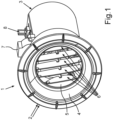
- Fig. 1 shows a schematic front view of an embodiment of an air outlet device 1.
- the air outlet device 1 has a cover 2.
- the air outlet device 1 also has a nozzle housing 3 and a funnel 4.
- Fig. 1 further shows that the air outlet device 1 has a rotating ring 5 and adjustable slats 6, which can also be referred to as a slat pack.
- the air outlet device 1 has an electric servomotor 7, which can also be referred to as a stepper motor, and a potentiometer 8.
- the air outlet device 1 is designed to supply tempered air for an interior of a motor vehicle, not shown.
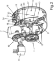
- Fig. 2 shows a schematic perspective view of a rear side of the air outlet device 1.
- the air outlet device 1 also has a stationary guide 9, which can also be referred to as a control disk.
- the air outlet device 1 also has a driving gear 10 and a driven gear 11 and a pin 12.
- the air outlet device 1 has struts 13 and a lever 14 for moving a control cam.
- the air outlet device 1 has a further pin 15 and a lever 16 for a control blade 17.
- the air outlet device 1 also has a first toothed segment 18, a second toothed segment 19 and a control pin 20.
- the air outlet device 1 has a control pin 20, an elongated hole 21, a rotation axis 22, a guide pin, which can also be referred to as a pin 23, and a rotation axis 24.
- Fig. 2 shows in particular that the air outlet device 1 is designed to supply tempered air for an interior of the motor vehicle.
- the air outlet device 1 has the electric servomotor 7 and the rotatably mounted rotating ring 5.
- the rotating ring 5 is coupled to the adjustable slats 6 in an inner region of the rotating ring 5.
- the air outlet device 1 has the stationary link guide 9, in which the pin 23 is connected to the slats 6, so that an adjustment of the slats 6 is realized by rotating the rotation ring 5.
- the link guide 9 is in particular star-shaped.
- the pin 23 is designed with the lever 14 for adjusting the slats 6.
- the rotation ring 5 can be connected to the rotation axis 22 by means of the struts 13, wherein the rotation axis 22 is connected to the electric servomotor 7 via at least one of the gears 10, 11. It is also shown that the air outlet device 1 has the potentiometer 7, wherein the potentiometer 8 is designed to store a position of the rotation ring 5 and the slats 6.
- the solution is provided in particular by the air outlet device 1 presented, which only requires the electric servomotor 7 to set any or a limited number of discrete outlet directions of the escaping air. This leads to a significant reduction in costs, as in solutions in which the vertical deflection is controlled by a stepper motor and the horizontal deflection by another stepper motor. Deflection of the air is achieved. Conditioned air from the heating and air conditioning system of the vehicle flows into the inlet area of the air outlet device 1, in that the electric servomotor 7 and the potentiometer 8 are housed in the kinematic element shown. In the nozzle housing 3, the rotary ring 5 in which the slats 6 are mounted can be rotated by means of the electric servomotor 7.
- any desired outflow direction of the air can be achieved.
- the funnel 4 and the cover 2 which is connected to an instrument panel of the motor vehicle.
- the rotary motion generated in the electric servomotor 7 is transmitted via the driving gear 10 to the driven gear 11 and via the rotation axis 22 to the rotation ring 5.
- the rotation axis 22 is firmly connected to the rotation ring 5 via the struts 13.
- the lever 14 has a guide pin, which in this case corresponds to the pin 23, which is connected to the nozzle housing 3 in the slotted guide 9, this being achieved in particular via the pins 12.
- the pin 23 engages in the star-shaped slotted guide 9.
- the lever 14 has the toothed segment 18, which is in engagement with the toothed segment 19 of the lever 16, which is mounted so as to be rotatable about the axis 24, by means of which the control lamella 17 is deflected via the control pin 20 and the entire lamella package, i.e. the lamellae 6, is deflected via a driver.
- the control pin 20 moves in the slot 21 of the lever 16. This means that when the rotating ring 5, which is driven by the electric servomotor 7, rotates, the lamella pack is simultaneously deflected to different degrees depending on the position of the pin 23 via the levers 14, 16 and the pin 23 guided in the guide 9.
- the potentiometer 8 stores the current position of the kinematics after the power supply is switched off, so that the system can continue to operate from this position after it is switched on again.
Landscapes
- Physics & Mathematics (AREA)
- Thermal Sciences (AREA)
- Engineering & Computer Science (AREA)
- Mechanical Engineering (AREA)
- Air-Flow Control Members (AREA)
- Air-Conditioning For Vehicles (AREA)
Description
- Die Erfindung betrifft eine Luftausströmvorrichtung zur Zuführung von temperierter Luft für einen Innenraum eines Kraftfahrzeugs gemäß dem Oberbegriff von Patentanspruch 1.
- Aus dem Stand der Technik sind bereits Luftausströmvorrichtungen für einen Innenraum von Kraftfahrzeugen bekannt. Diese sind zum Ausströmen von temperierter Luft für einen Insassen ausgebildet. Hierzu können beispielsweise Lamellen innerhalb der Luftausströmöffnung ausgebildet sein, wodurch eine Richtung der Luftströmung durch einen Insassen eingestellt werden kann.
- Die
DE 10 2015 000 874 A1 betrifft einen Luftausströmer für einen Fahrgastraum eines Kraftwagens. Der Luftausströmer weist einen zylinderrohrförmigen Lamellenträger mit schwenkbar in ihm gelagerten Lamellen auf. Mit einem elektromotorischen Antrieb ist der Lamellenträger mit den Lamellen drehend antreibbar. Ein axial verschieblicher Stellring auf dem Lamellenträger ermöglicht ein Schwenken der Lamellen in jeder beliebigen Drehstellung des Lamellenträgers. Über einen Stellschieber verschiebt eine Steuerkurve auf einem Zylinder den Stellring axial. Der Antrieb des Zylinders erfolgt ebenfalls mit dem elektromotorischen Antrieb der wahlweise auf ein Zahnrad zum Drehen des Lamellenträgers oder den Zylinder mit Steuerkurve umschaltbar ist. - Die
DE 20 2009 005 243 U1 zeigt eine Runddüse zum Leiten von Luftströmen, insbesondere in Heizungs-, Klima- und Belüftungsanlagen in Kraftfahrzeugen, mindestens aufweisend ein Gehäuse mit mindestens einer zylinderförmigen Öffnung mit daran befestigten Luftableitscheiben, einem Stellring zum Verstellen der Luftableitscheiben, der an der Öffnungswand des Gehäuses drehbar gelagert ist, dadurch gekennzeichnet, dass als Luftableitmittel mindestens zwei Luftableitscheiben vorgesehen sind, die an einer Achse oder einer Welle fest oder in Längsrichtung der Achse oder Welle auslenkbar, symmetrisch oder asymmetrisch zueinander verdrehsicher angeordnet sind, wobei die Luftableitscheiben eine solche Kontur aufweisen, dass durch Drehen der Welle um die Längsachse oder durch Drehen des Stellrings mit der quer eingesetzten Achse die Luftableitscheiben verschiedene Ableitstellungen gegenüber der Längsachse der Achse oder Welle und/oder des Gehäuses einnehmen und verschiedene Strömungsablenkungen bewirken. - Aus der
US 2019 / 077 218 A1 ist ein System zur Steuerung des Luftstroms einer Heizungs-, Lüftungs- und Klimaanlage (HLK) bekannt. Das System umfasst ein Register mit Luftstromrichtungen. Ein Motor ist an das Register angeschlossen, um die Richtungen zu bewegen. Ein Richtungswähler ist an den Motor angeschlossen, um den Motor zu steuern. Die Betätigung des Richtungswählers durch einen Benutzer ändert die Position der Richtungswahlschalter. Ein Steuermodul speichert vorbestimmte Positionen der Richtungen und steuert den Motor, um die Richtungen als Reaktion auf den Empfang eines Benutzerbefehls in die vorbestimmten Positionen zu bewegen. - Weiterer relevanter Stand der Technik ist der
JP S57 143182 A - Aufgabe der vorliegenden Erfindung ist es, eine Luftausströmvorrichtung zu schaffen, mittels welcher eine verbesserte Zuführung von temperierter Luft für einen Insassen eines Kraftfahrzeugs realisiert werden kann.
- Diese Aufgabe wird durch eine Luftausströmvorrichtung gemäß dem unabhängigen Patentanspruch 1 gelöst. Vorteilhafte Ausgestaltungsformen sind in den Unteransprüchen angegeben.
- Ein Aspekt der Erfindung betrifft eine Luftausströmvorrichtung zur Zuführung von temperierter Luft für einen Innenraum eines Kraftfahrzeugs, mit zumindest einem elektrischen Stellmotor und mit einem drehbar gelagerten Rotationsring, wobei der Rotationsring in einem Innenbereich des Rotationsrings verstellbare Lamellen aufweist. Es ist vorgesehen, dass die Luftausströmvorrichtung eine ortsfeste Kulissenführung aufweist, in welcher ein Zapfen des Rotationsrings eingreift, wobei der Zapfen mit den Lamellen verbunden ist, sodass durch eine Drehung des Rotationsrings eine Verstellung der Lamellen realisiert ist.
- Insbesondere ist somit eine aktuatorische Runddüse zur Zuführung von klimatisierter Luft in einen Fahrzeuginnenraum vorgesehen. Mithilfe des elektrischen Stellmotors, welcher insbesondere ein Schrittmotor ist, kann der Rotationsring mit an diesem drehbar gelagerten angebrachten Lamellen in einem Düsengehäuse zur Einstellung beliebiger Luftaustrittsrichtungen gedreht werden. Hierzu wird über einen Hebel und eine entsprechende Steuerscheibe ein Zapfen, geführt der die Schwenkbewegung durchführt. Wenn der Zapfen in der Kulissenführung sich bewegt hat, wird die Neigung der Lamellen einmal von Minimum nach Maximum und wieder zurück nach Minimum verstellt. Gleichzeitig wird der Rotationsring ein Stück weitergedreht. Weiterhin ist der Zapfen mit dem Hebel gekoppelt, welcher mit dem Rotationsring drehbar gelagert ist und der Hebel zum Verstellen der Lamellen ausgebildet ist.
- Gemäß einer vorteilhaften Ausgestaltungsform ist die Kulissenführung sternförmig ausgebildet.
- In einer weiteren vorteilhaften Ausgestaltungsform ist der Rotationsring mittels zumindest einer Strebe mit einer Rotationsachse verbunden, wobei die Rotationsachse mit dem elektrischen Stellmotor über zumindest ein Zahnrad verbunden ist. Ferner hat es sich als vorteilhaft erwiesen, wenn die Luftausströmvorrichtung ein Potentiometer aufweist, wobei das Potentiometer zum Speichern einer Stellung des Rotationsrings und der Lamellen ausgebildet ist.
- Ein weiterer Aspekt der Erfindung betrifft ein Kraftfahrzeug mit einer Luftausströmvorrichtung gemäß dem vorhergehenden Aspekt. Das Kraftfahrzeug ist insbesondere als Personenkraftwagen ausgebildet.
- Vorteilhafte Ausgestaltungsformen der Luftausströmvorrichtung sind als vorteilhafte Ausgestaltungsformen des Kraftfahrzeugs anzusehen.
- Weitere Vorteile und Einzelheiten der Erfindung ergeben sich aus der nachfolgenden Beschreibung eines bevorzugten Ausführungsbeispiels sowie anhand der Zeichnung. Die vorstehend in der Beschreibung genannten Merkmale und Merkmalskombinationen sowie die nachfolgend in der Figurenbeschreibung genannten und/oder in der Figur alleine gezeigten Merkmale und Merkmalskombinationen sind nicht nur in der jeweils angegebenen Kombination, sondern auch in anderen Kombinationen oder in Alleinstellung verwendbar.
- Dabei zeigen:
- Fig. 1
- eine schematische Frontansicht einer Ausführungsform einer Luftausströmvorrichtung; und
- Fig. 2
- eine schematische Perspektivansicht einer Rückseite der Luftausströmvorrichtung gemäß
Fig. 1 . - In den Fig. sind gleiche oder funktionsgleiche Elemente mit den gleichen Bezugszeichen versehen.
-
Fig. 1 zeigt eine schematische Frontansicht einer Ausführungsform einer Luftausströmvorrichtung 1. Die Luftausströmvorrichtung 1 weist eine Blende 2 auf. Ferner weist die Luftausströmvorrichtung 1 ein Düsengehäuse 3 sowie einen Trichter 4 auf.Fig. 1 zeigt ferner, dass die Luftausströmvorrichtung 1 einen Rotationsring 5 sowie verstellbare Lamellen 6, welche auch als Lamellenpaket bezeichnet werden können, aufweist. Ferner weist die Luftausströmvorrichtung 1 einen elektrischen Stellmotor 7, welcher auch als Schrittmotor bezeichnet werden kann, sowie ein Potentiometer 8 auf. - Die Luftausströmvorrichtung 1 ist zur Zuführung von temperierter Luft für einen Innenraum eines nicht gezeigten Kraftfahrzeugs ausgebildet.
-
Fig. 2 zeigt eine schematische Perspektivansicht einer Rückseite der Luftausströmvorrichtung 1. Vorliegend ist insbesondere gezeigt, dass die Luftausströmvorrichtung 1 ferner eine ortsfeste Kulissenführung 9 aufweist, welche auch als Steuerscheibe bezeichnet werden kann. Ferner weist die Luftausströmvorrichtung 1 ein treibendes Zahnrad 10 sowie ein getriebenes Zahnrad 11 und einen Zapfen 12 auf. Ferner ist vorgesehen, dass die Luftausströmvorrichtung 1 Streben 13 sowie einen Hebel 14 zum Bewegen einer Steuerkurve aufweist. Ferner ist vorgesehen, dass die Luftausströmvorrichtung 1 einen weiteren Zapfen 15 und einen Hebel 16 für eine Steuerlamelle 17 aufweist. Ferner weist die Luftausströmvorrichtung 1 ein erstes Zahnsegment 18, ein zweites Zahnsegment 19 sowie einen Steuerzapfen 20 auf. Ferner ist gezeigt, dass die Luftausströmvorrichtung 1 einen Steuerzapfen 20, ein Langloch 21, eine Rotationsachse 22, einen Führungsstift, der ebenfalls als Zapfen 23 bezeichnet werden kann, sowie eine Drehachse 24 aufweist. -
Fig. 2 zeigt insbesondere, dass die Luftausströmvorrichtung 1 zur Zuführung von temperierter Luft für einen Innenraum des Kraftfahrzeugs ausgebildet ist. Hierzu weist die Luftausströmvorrichtung 1 den elektrischen Stellmotor 7 auf und der drehbar gelagerten Rotationsring 5. Der Rotationsring 5 ist in einem Innenbereich des Rotationsrings 5 mit den verstellbaren Lamellen 6 gekoppelt. - Die Luftausströmvorrichtung 1 weist die ortsfeste Kulissenführung 9 auf, in welche der Zapfen 23 mit den Lamellen 6 verbunden ist, sodass durch eine Drehung des Rotationsrings 5 eine Verstellung der Lamellen 6 realisiert ist. Die Kulissenführung 9 ist insbesondere sternförmig ausgebildet. Ferner ist der Zapfen 23 mit dem Hebel 14 zum Verstellen der Lamellen 6 ausgebildet. Der Rotationsring 5 kann mittels der Streben 13 mit der Rotationsachse 22 verbunden sein, wobei die Rotationsachse 22 mit dem elektrischen Stellmotor 7 über zumindest eines der Zahnräder 10, 11 verbunden ist. Ferner ist gezeigt, dass die Luftausströmvorrichtung 1 das Potentiometer 7 aufweist, wobei das Potentiometer 8 zum Speichern einer Stellung des Rotationsrings 5 und der Lamellen 6 ausgebildet ist.
- Insbesondere ist somit gezeigt, dass auf Basis des elektrischen Stellmotors 7 eine manuelle Bedienung durch einen Nutzer entfallen kann. Ein Insasse kann die für ihn optimale Luftausströmrichtung durch beispielsweise Sprachbedienung oder auf einem Touchscreen einfach einstellen. Eine bevorzugte Düsenposition kann individuell gespeichert und wieder abgerufen werden. Zudem lassen sich aktuatorische Düsen, wie die Luftausströmvorrichtung 1, in die Klimaregelung einbinden. Insgesamt ergibt sich damit eine Individualisierung und Verbesserung des thermischen Komforts für einen Insassen. Zudem wird die im aus der Luftausströmvorrichtung 1 ausströmenden Luftstrom enthaltene Klimatisierungsenergie, beispielsweise Warm- oder Kaltluft, effizienter zum Insassen gebracht, wodurch Energie zur Klimatisierung des Fahrzeuginnenraums eingespart werden kann.
- Die Lösung besteht insbesondere durch die vorgestellte Luftausströmvorrichtung 1, die lediglich den elektrischen Stellmotor 7 benötigt, um beliebig beziehungsweise eine begrenzte Anzahl von diskreten Ausströmrichtungen der austretenden Luft einzustellen. Dies führt zu einer deutlichen Kostensenkung wie bei Lösungen, bei denen mit einem Schrittmotor die vertikale Ablenkung und mit einem weiteren Schrittmotor die horizontale Ablenkung der Luft bewerkstelligt wird. In den Eintrittsbereich der Luftausströmvorrichtung 1 wird klimatisierte Luft aus der Heizungs- und Klimaanlage des Fahrzeugs eingeströmt, indem der elektrische Stellmotor 7 und das Potentiometer 8 in dem dargestellten Kinematikelement untergebracht sind. Im Düsengehäuse 3 kann mittels des elektrischen Stellmotors 7 der Rotationsring 5, in dem die Lamellen 6 gelagert sind, gedreht werden. Durch diese Drehung sowie der Auslenkung der Lamellen 6 des Lamellenpakets können beliebige Ausströmrichtungen der Luft realisiert werden. Im vorderen Bereich der Luftausströmvorrichtung 1 befinden sich der Trichter 4 und die Blende 2, die mit einer Instrumententafel des Kraftfahrzeugs verbunden ist.
- Die in dem elektrischen Stellmotor 7 erzeugte Drehbewegung wird über das treibende Zahnrad 10 auf das getriebene Zahnrad 11 und über die Rotationsachse 22 auf den Rotationsring 5 übertragen. Die Rotationsachse 22 ist über die Streben 13 fest mit dem Rotationsring 5 verbunden. An einem Ende weist der Hebel 14 einen Führungsstift, welcher vorliegend dem Zapfen 23 entspricht, auf, der in der Kulissenführung 9 mit dem Düsengehäuse 3 verbunden ist, wobei dies jeweils insbesondere über die Zapfen 12 realisiert ist. Der Zapfen 23 greift dabei in die sternförmige Kulissenführung 9 ein. An seinem anderen Ende weist der Hebel 14 das Zahnsegment 18 auf, das im Eingriff mit dem Zahnsegment 19 des um die Achse 24 drehbar gelagerten Hebels 16 steht, durch den über den Steuerzapfen 20 die Steuerlamelle 17 und über einen Mitnehmer das gesamte Lamellenpaket, also die Lamellen 6, ausgelenkt werden. Der Steuerzapfen 20 bewegt sich dabei in dem Langloch 21 des Hebels 16. Das heißt, bei Drehung des durch den elektrischen Stellmotor 7 angetriebenen Rotationsrings 5 wird über die Hebel 14, 16 und den in der Kulissenführung 9 geführten Zapfen 23 gleichzeitig das Lamellenpaket abhängig von der Stellung des Zapfens 23 verschieden stark ausgelenkt. Durch das Potentiometer 8 ist die aktuelle Position der Kinematik nach Ausschalten der Spannungsversorgung gespeichert, sodass sich das System nach Wiedereinschalten von dieser Position aus weiter betreiben lässt.
- Insgesamt zeigt die Fig. eine aktuatorische Runddüse.
Claims (4)
- Luftausströmvorrichtung (1) zur Zuführung von temperierter Luft für einen Innenraum eines Kraftfahrzeugs, mit zumindest einem elektrischen Stellmotor (7) und mit einem drehbar gelagerten Rotationsring (5), wobei der Rotationsring (5) in einem Innenbereich des Rotationsrings (5) verstellbare Lamellen (6) aufweist, dadurch gekennzeichnet, dass
die Luftausströmvorrichtung (1) eine ortsfeste Kulissenführung (9) aufweist, in welche ein Zapfen (23) des Rotationsrings (5) eingreift, wobei der Zapfen (23) mit den Lamellen (6) verbunden ist, so dass durch eine Drehung des Rotationsrings (5) eine Verstellung der Lamellen (6) realisiert ist, wobei der Zapfen (23) mit einem Hebel (14) gekoppelt ist, welcher mit dem Rotationsring (5) drehbar gelagert ist, und der Hebel (14) zum Verstellen der Lamellen (6) ausgebildet ist. - Luftausströmvorrichtung (1) nach Anspruch 1,
dadurch gekennzeichnet, dass
die Kulissenführung (9) sternförmig ausgebildet ist. - Luftausströmvorrichtung (1) nach einem der vorhergehenden Ansprüche,
dadurch gekennzeichnet, dass
der Rotationsring (5) mittels zumindest einer Strebe (13) mit einer Rotationsachse (22) verbunden ist, wobei die Rotationsachse (22) mit dem elektrischen Stellmotor (7) über zumindest ein Zahnrad (10, 11) verbunden ist. - Luftausströmvorrichtung (1) nach einem der vorhergehenden Ansprüche,
dadurch gekennzeichnet, dass
die Luftausströmvorrichtung (1) ein Potentiometer (8) aufweist, wobei das Potentiometer (8) zum Speichern einer Stellung des Rotationsrings (5) und der Lamellen (6) ausgebildet ist.
Applications Claiming Priority (2)
| Application Number | Priority Date | Filing Date | Title |
|---|---|---|---|
| DE102021000255.5A DE102021000255A1 (de) | 2021-01-19 | 2021-01-19 | Luftausströmvorrichtung zur Zuführung von temperierter Luft für einen Innenraum eines Kraftfahrzeugs |
| PCT/EP2021/083059 WO2022156941A1 (de) | 2021-01-19 | 2021-11-25 | Luftausströmvorrichtung zur zuführung von temperierter luft für einen innenraum eines kraftfahrzeugs |
Publications (3)
| Publication Number | Publication Date |
|---|---|
| EP4281302A1 EP4281302A1 (de) | 2023-11-29 |
| EP4281302C0 EP4281302C0 (de) | 2024-10-02 |
| EP4281302B1 true EP4281302B1 (de) | 2024-10-02 |
Family
ID=78827551
Family Applications (1)
| Application Number | Title | Priority Date | Filing Date |
|---|---|---|---|
| EP21823206.4A Active EP4281302B1 (de) | 2021-01-19 | 2021-11-25 | Luftausströmvorrichtung zur zuführung von temperierter luft für einen innenraum eines kraftfahrzeugs |
Country Status (5)
| Country | Link |
|---|---|
| US (1) | US20240083221A1 (de) |
| EP (1) | EP4281302B1 (de) |
| CN (1) | CN116635256A (de) |
| DE (1) | DE102021000255A1 (de) |
| WO (1) | WO2022156941A1 (de) |
Family Cites Families (13)
| Publication number | Priority date | Publication date | Assignee | Title |
|---|---|---|---|---|
| JPS57148132A (en) * | 1981-03-09 | 1982-09-13 | Nippon Denso Co Ltd | Blowing-off grill of air conditioner |
| US5440486A (en) * | 1993-06-01 | 1995-08-08 | Chrysler Corporation | Predictive electric motor positioning device, normal operating system therefor |
| DE102007010795A1 (de) * | 2007-03-02 | 2008-09-04 | Behr Gmbh & Co. Kg | Luftausströmer mit Drallströmung und konventioneller Strömung |
| DE202008000059U1 (de) * | 2008-05-19 | 2008-12-24 | Dr. Schneider Kunststoffwerke Gmbh | Luftdüse |
| DE202009005243U1 (de) * | 2009-09-07 | 2009-11-19 | Dr. Schneider Kunststoffwerke Gmbh | Runddüse mit auf einer Achse gelagerten Luftableitscheiben |
| DE102015000874A1 (de) | 2015-01-23 | 2016-07-28 | Fischer Automotive Systems Gmbh & Co. Kg | Luftausströmer |
| DE102015118548B4 (de) * | 2015-05-28 | 2017-05-04 | Dr. Schneider Kunststoffwerke Gmbh | Luftausströmer mit einer Steuereinrichtung |
| DE102016110933B3 (de) * | 2016-06-15 | 2017-05-18 | Dr. Schneider Kunststoffwerke Gmbh | Luftausströmer |
| US10668786B2 (en) * | 2017-09-11 | 2020-06-02 | Denso International America, Inc. | HVAC register recall position system |
| DE102017217085A1 (de) * | 2017-09-26 | 2019-03-28 | Ford Global Technologies, Llc | Luftausströmer zur Steuerung eines Luftstroms |
| EP3590744B1 (de) * | 2018-07-06 | 2021-01-20 | Volvo Car Corporation | Einstellbarer luftausströmer |
| CN109515120B (zh) * | 2018-12-21 | 2023-09-15 | 华晨鑫源重庆汽车有限公司 | 可发光汽车空调出风口结构 |
| CN110228354B (zh) * | 2019-06-10 | 2022-03-01 | 上海延锋金桥汽车饰件系统有限公司 | 出风口及包括其的车辆 |
-
2021
- 2021-01-19 DE DE102021000255.5A patent/DE102021000255A1/de not_active Withdrawn
- 2021-11-25 CN CN202180086723.6A patent/CN116635256A/zh active Pending
- 2021-11-25 US US18/261,972 patent/US20240083221A1/en active Pending
- 2021-11-25 WO PCT/EP2021/083059 patent/WO2022156941A1/de not_active Ceased
- 2021-11-25 EP EP21823206.4A patent/EP4281302B1/de active Active
Also Published As
| Publication number | Publication date |
|---|---|
| EP4281302A1 (de) | 2023-11-29 |
| WO2022156941A1 (de) | 2022-07-28 |
| US20240083221A1 (en) | 2024-03-14 |
| CN116635256A (zh) | 2023-08-22 |
| EP4281302C0 (de) | 2024-10-02 |
| DE102021000255A1 (de) | 2022-07-21 |
Similar Documents
| Publication | Publication Date | Title |
|---|---|---|
| EP3192684B1 (de) | Einrichtung zum verstellen von lamellen eines luftausströmers | |
| DE102015115530A1 (de) | Multifunktionales und multidirektionales Belüftungssystem | |
| EP3530506B1 (de) | Luftausströmer | |
| DE102018005002A1 (de) | Luftausströmer für einen Kraftwagen, insbesondere für einen Personenkraftwagen | |
| DE102016121727B4 (de) | Belüftungseinrichtung für ein Fahrzeug | |
| DE102017217085A1 (de) | Luftausströmer zur Steuerung eines Luftstroms | |
| EP3381725B1 (de) | Luftausströmer | |
| DE3813116A1 (de) | Belueftungsanlage fuer ein kraftfahrzeug | |
| DE102019116668A1 (de) | Ausströmdüse eines Kraftfahrzeugs | |
| EP1910110B1 (de) | Vorrichtung zur belüftung von fahrzeugen | |
| DE202007010190U1 (de) | Luftdüse | |
| EP3921195A1 (de) | Bedieneinrichtung für ein verschwenkbar gelagertes luftleitelement | |
| DE102021111535A1 (de) | Luftausströmeranordnung | |
| DE102019132921B4 (de) | Luftausströmer mit Bedieneinrichtung | |
| DE202005012570U1 (de) | Luftdüse | |
| DE102009047959B4 (de) | Heizungs-, Lüftungs- und Klimatisierungssystem für ein Fahrzeug | |
| EP1708899A1 (de) | Stellvorrichtung und heizungs- oder klimatisierungseinrichtung | |
| EP0417351B1 (de) | Ausströmdüse für Belüftungs- oder Klimaanlagen | |
| DE202004016983U1 (de) | Luftdüse | |
| DE19716229A1 (de) | Vorrichtung zur Betätigung von verschwenkbaren Stellgliedern | |
| DE19816013B4 (de) | Luftstromverteiler für einen Kraftfahrzeuginnenraum | |
| DE102015101970B4 (de) | Belüftungseinrichtung für ein Fahrzeugarmaturenbrett | |
| DE102019121738A1 (de) | Bedieneinrichtung für ein verschwenkbar gelagertes Luftleitelement und Luftausströmer mit Bedieneinrichtung | |
| DE102005037748B3 (de) | Luftdüse | |
| DE10152480A1 (de) | Belüftungseinheit, insbesondere zur Verwendung in Kraftfahrzeugen |
Legal Events
| Date | Code | Title | Description |
|---|---|---|---|
| STAA | Information on the status of an ep patent application or granted ep patent |
Free format text: STATUS: UNKNOWN |
|
| STAA | Information on the status of an ep patent application or granted ep patent |
Free format text: STATUS: THE INTERNATIONAL PUBLICATION HAS BEEN MADE |
|
| PUAI | Public reference made under article 153(3) epc to a published international application that has entered the european phase |
Free format text: ORIGINAL CODE: 0009012 |
|
| STAA | Information on the status of an ep patent application or granted ep patent |
Free format text: STATUS: REQUEST FOR EXAMINATION WAS MADE |
|
| 17P | Request for examination filed |
Effective date: 20230620 |
|
| AK | Designated contracting states |
Kind code of ref document: A1 Designated state(s): AL AT BE BG CH CY CZ DE DK EE ES FI FR GB GR HR HU IE IS IT LI LT LU LV MC MK MT NL NO PL PT RO RS SE SI SK SM TR |
|
| DAV | Request for validation of the european patent (deleted) | ||
| DAX | Request for extension of the european patent (deleted) | ||
| GRAP | Despatch of communication of intention to grant a patent |
Free format text: ORIGINAL CODE: EPIDOSNIGR1 |
|
| STAA | Information on the status of an ep patent application or granted ep patent |
Free format text: STATUS: GRANT OF PATENT IS INTENDED |
|
| INTG | Intention to grant announced |
Effective date: 20240704 |
|
| GRAS | Grant fee paid |
Free format text: ORIGINAL CODE: EPIDOSNIGR3 |
|
| GRAA | (expected) grant |
Free format text: ORIGINAL CODE: 0009210 |
|
| STAA | Information on the status of an ep patent application or granted ep patent |
Free format text: STATUS: THE PATENT HAS BEEN GRANTED |
|
| AK | Designated contracting states |
Kind code of ref document: B1 Designated state(s): AL AT BE BG CH CY CZ DE DK EE ES FI FR GB GR HR HU IE IS IT LI LT LU LV MC MK MT NL NO PL PT RO RS SE SI SK SM TR |
|
| REG | Reference to a national code |
Ref country code: GB Ref legal event code: FG4D Free format text: NOT ENGLISH |
|
| REG | Reference to a national code |
Ref country code: CH Ref legal event code: EP |
|
| REG | Reference to a national code |
Ref country code: IE Ref legal event code: FG4D Free format text: LANGUAGE OF EP DOCUMENT: GERMAN |
|
| REG | Reference to a national code |
Ref country code: DE Ref legal event code: R096 Ref document number: 502021005366 Country of ref document: DE |
|
| U01 | Request for unitary effect filed |
Effective date: 20241024 |
|
| U07 | Unitary effect registered |
Designated state(s): AT BE BG DE DK EE FI FR IT LT LU LV MT NL PT RO SE SI Effective date: 20241107 |
|
| U20 | Renewal fee for the european patent with unitary effect paid |
Year of fee payment: 4 Effective date: 20241127 |
|
| PG25 | Lapsed in a contracting state [announced via postgrant information from national office to epo] |
Ref country code: HR Free format text: LAPSE BECAUSE OF FAILURE TO SUBMIT A TRANSLATION OF THE DESCRIPTION OR TO PAY THE FEE WITHIN THE PRESCRIBED TIME-LIMIT Effective date: 20241002 Ref country code: IS Free format text: LAPSE BECAUSE OF FAILURE TO SUBMIT A TRANSLATION OF THE DESCRIPTION OR TO PAY THE FEE WITHIN THE PRESCRIBED TIME-LIMIT Effective date: 20250202 |
|
| PG25 | Lapsed in a contracting state [announced via postgrant information from national office to epo] |
Ref country code: ES Free format text: LAPSE BECAUSE OF FAILURE TO SUBMIT A TRANSLATION OF THE DESCRIPTION OR TO PAY THE FEE WITHIN THE PRESCRIBED TIME-LIMIT Effective date: 20241002 |
|
| PG25 | Lapsed in a contracting state [announced via postgrant information from national office to epo] |
Ref country code: NO Free format text: LAPSE BECAUSE OF FAILURE TO SUBMIT A TRANSLATION OF THE DESCRIPTION OR TO PAY THE FEE WITHIN THE PRESCRIBED TIME-LIMIT Effective date: 20250102 |
|
| PG25 | Lapsed in a contracting state [announced via postgrant information from national office to epo] |
Ref country code: GR Free format text: LAPSE BECAUSE OF FAILURE TO SUBMIT A TRANSLATION OF THE DESCRIPTION OR TO PAY THE FEE WITHIN THE PRESCRIBED TIME-LIMIT Effective date: 20250103 |
|
| PG25 | Lapsed in a contracting state [announced via postgrant information from national office to epo] |
Ref country code: CZ Free format text: LAPSE BECAUSE OF FAILURE TO SUBMIT A TRANSLATION OF THE DESCRIPTION OR TO PAY THE FEE WITHIN THE PRESCRIBED TIME-LIMIT Effective date: 20241002 Ref country code: PL Free format text: LAPSE BECAUSE OF FAILURE TO SUBMIT A TRANSLATION OF THE DESCRIPTION OR TO PAY THE FEE WITHIN THE PRESCRIBED TIME-LIMIT Effective date: 20241002 |
|
| PG25 | Lapsed in a contracting state [announced via postgrant information from national office to epo] |
Ref country code: RS Free format text: LAPSE BECAUSE OF FAILURE TO SUBMIT A TRANSLATION OF THE DESCRIPTION OR TO PAY THE FEE WITHIN THE PRESCRIBED TIME-LIMIT Effective date: 20250102 |
|
| REG | Reference to a national code |
Ref country code: CH Ref legal event code: PL |
|
| PG25 | Lapsed in a contracting state [announced via postgrant information from national office to epo] |
Ref country code: SM Free format text: LAPSE BECAUSE OF FAILURE TO SUBMIT A TRANSLATION OF THE DESCRIPTION OR TO PAY THE FEE WITHIN THE PRESCRIBED TIME-LIMIT Effective date: 20241002 |
|
| PG25 | Lapsed in a contracting state [announced via postgrant information from national office to epo] |
Ref country code: MC Free format text: LAPSE BECAUSE OF FAILURE TO SUBMIT A TRANSLATION OF THE DESCRIPTION OR TO PAY THE FEE WITHIN THE PRESCRIBED TIME-LIMIT Effective date: 20241002 |
|
| REG | Reference to a national code |
Ref country code: CH Ref legal event code: PL |
|
| PG25 | Lapsed in a contracting state [announced via postgrant information from national office to epo] |
Ref country code: CH Free format text: LAPSE BECAUSE OF NON-PAYMENT OF DUE FEES Effective date: 20241130 |
|
| PG25 | Lapsed in a contracting state [announced via postgrant information from national office to epo] |
Ref country code: SK Free format text: LAPSE BECAUSE OF FAILURE TO SUBMIT A TRANSLATION OF THE DESCRIPTION OR TO PAY THE FEE WITHIN THE PRESCRIBED TIME-LIMIT Effective date: 20241002 |
|
| PLBE | No opposition filed within time limit |
Free format text: ORIGINAL CODE: 0009261 |
|
| STAA | Information on the status of an ep patent application or granted ep patent |
Free format text: STATUS: NO OPPOSITION FILED WITHIN TIME LIMIT |
|
| 26N | No opposition filed |
Effective date: 20250703 |
|
| PG25 | Lapsed in a contracting state [announced via postgrant information from national office to epo] |
Ref country code: IE Free format text: LAPSE BECAUSE OF NON-PAYMENT OF DUE FEES Effective date: 20241125 |
|
| U20 | Renewal fee for the european patent with unitary effect paid |
Year of fee payment: 5 Effective date: 20251126 |
|
| PG25 | Lapsed in a contracting state [announced via postgrant information from national office to epo] |
Ref country code: HU Free format text: LAPSE BECAUSE OF FAILURE TO SUBMIT A TRANSLATION OF THE DESCRIPTION OR TO PAY THE FEE WITHIN THE PRESCRIBED TIME-LIMIT; INVALID AB INITIO Effective date: 20211125 |
|
| PG25 | Lapsed in a contracting state [announced via postgrant information from national office to epo] |
Ref country code: CY Free format text: LAPSE BECAUSE OF FAILURE TO SUBMIT A TRANSLATION OF THE DESCRIPTION OR TO PAY THE FEE WITHIN THE PRESCRIBED TIME-LIMIT; INVALID AB INITIO Effective date: 20211125 |