EP4279250A2 - Klebefilm, filmklebewerkzeug und filmklebeanordnung - Google Patents
Klebefilm, filmklebewerkzeug und filmklebeanordnung Download PDFInfo
- Publication number
- EP4279250A2 EP4279250A2 EP22188746.6A EP22188746A EP4279250A2 EP 4279250 A2 EP4279250 A2 EP 4279250A2 EP 22188746 A EP22188746 A EP 22188746A EP 4279250 A2 EP4279250 A2 EP 4279250A2
- Authority
- EP
- European Patent Office
- Prior art keywords
- film
- sticking
- screen
- tempered
- film layer
- Prior art date
- Legal status (The legal status is an assumption and is not a legal conclusion. Google has not performed a legal analysis and makes no representation as to the accuracy of the status listed.)
- Granted
Links
Images


Classifications
-
- B—PERFORMING OPERATIONS; TRANSPORTING
- B29—WORKING OF PLASTICS; WORKING OF SUBSTANCES IN A PLASTIC STATE IN GENERAL
- B29C—SHAPING OR JOINING OF PLASTICS; SHAPING OF MATERIAL IN A PLASTIC STATE, NOT OTHERWISE PROVIDED FOR; AFTER-TREATMENT OF THE SHAPED PRODUCTS, e.g. REPAIRING
- B29C63/00—Lining or sheathing, i.e. applying preformed layers or sheathings of plastics; Apparatus therefor
- B29C63/02—Lining or sheathing, i.e. applying preformed layers or sheathings of plastics; Apparatus therefor using sheet or web-like material
-
- B—PERFORMING OPERATIONS; TRANSPORTING
- B32—LAYERED PRODUCTS
- B32B—LAYERED PRODUCTS, i.e. PRODUCTS BUILT-UP OF STRATA OF FLAT OR NON-FLAT, e.g. CELLULAR OR HONEYCOMB, FORM
- B32B37/00—Methods or apparatus for laminating, e.g. by curing or by ultrasonic bonding
- B32B37/0046—Methods or apparatus for laminating, e.g. by curing or by ultrasonic bonding characterised by constructional aspects of the apparatus
-
- B—PERFORMING OPERATIONS; TRANSPORTING
- B29—WORKING OF PLASTICS; WORKING OF SUBSTANCES IN A PLASTIC STATE IN GENERAL
- B29C—SHAPING OR JOINING OF PLASTICS; SHAPING OF MATERIAL IN A PLASTIC STATE, NOT OTHERWISE PROVIDED FOR; AFTER-TREATMENT OF THE SHAPED PRODUCTS, e.g. REPAIRING
- B29C63/00—Lining or sheathing, i.e. applying preformed layers or sheathings of plastics; Apparatus therefor
- B29C63/0043—Fixing the layers by electrostatic charges, by the use of structured surfaces or by mechanical means
-
- B—PERFORMING OPERATIONS; TRANSPORTING
- B32—LAYERED PRODUCTS
- B32B—LAYERED PRODUCTS, i.e. PRODUCTS BUILT-UP OF STRATA OF FLAT OR NON-FLAT, e.g. CELLULAR OR HONEYCOMB, FORM
- B32B17/00—Layered products essentially comprising sheet glass, or glass, slag, or like fibres
- B32B17/06—Layered products essentially comprising sheet glass, or glass, slag, or like fibres comprising glass as the main or only constituent of a layer, next to another layer of a specific material
- B32B17/10—Layered products essentially comprising sheet glass, or glass, slag, or like fibres comprising glass as the main or only constituent of a layer, next to another layer of a specific material of synthetic resin
-
- B—PERFORMING OPERATIONS; TRANSPORTING
- B32—LAYERED PRODUCTS
- B32B—LAYERED PRODUCTS, i.e. PRODUCTS BUILT-UP OF STRATA OF FLAT OR NON-FLAT, e.g. CELLULAR OR HONEYCOMB, FORM
- B32B27/00—Layered products comprising a layer of synthetic resin
- B32B27/36—Layered products comprising a layer of synthetic resin comprising polyesters
-
- B—PERFORMING OPERATIONS; TRANSPORTING
- B32—LAYERED PRODUCTS
- B32B—LAYERED PRODUCTS, i.e. PRODUCTS BUILT-UP OF STRATA OF FLAT OR NON-FLAT, e.g. CELLULAR OR HONEYCOMB, FORM
- B32B37/00—Methods or apparatus for laminating, e.g. by curing or by ultrasonic bonding
- B32B37/14—Methods or apparatus for laminating, e.g. by curing or by ultrasonic bonding characterised by the properties of the layers
- B32B37/16—Methods or apparatus for laminating, e.g. by curing or by ultrasonic bonding characterised by the properties of the layers with all layers existing as coherent layers before laminating
- B32B37/18—Methods or apparatus for laminating, e.g. by curing or by ultrasonic bonding characterised by the properties of the layers with all layers existing as coherent layers before laminating involving the assembly of discrete sheets or panels only
-
- B—PERFORMING OPERATIONS; TRANSPORTING
- B32—LAYERED PRODUCTS
- B32B—LAYERED PRODUCTS, i.e. PRODUCTS BUILT-UP OF STRATA OF FLAT OR NON-FLAT, e.g. CELLULAR OR HONEYCOMB, FORM
- B32B7/00—Layered products characterised by the relation between layers; Layered products characterised by the relative orientation of features between layers, or by the relative values of a measurable parameter between layers, i.e. products comprising layers having different physical, chemical or physicochemical properties; Layered products characterised by the interconnection of layers
- B32B7/04—Interconnection of layers
- B32B7/06—Interconnection of layers permitting easy separation
-
- B—PERFORMING OPERATIONS; TRANSPORTING
- B32—LAYERED PRODUCTS
- B32B—LAYERED PRODUCTS, i.e. PRODUCTS BUILT-UP OF STRATA OF FLAT OR NON-FLAT, e.g. CELLULAR OR HONEYCOMB, FORM
- B32B7/00—Layered products characterised by the relation between layers; Layered products characterised by the relative orientation of features between layers, or by the relative values of a measurable parameter between layers, i.e. products comprising layers having different physical, chemical or physicochemical properties; Layered products characterised by the interconnection of layers
- B32B7/04—Interconnection of layers
- B32B7/12—Interconnection of layers using interposed adhesives or interposed materials with bonding properties
-
- C—CHEMISTRY; METALLURGY
- C09—DYES; PAINTS; POLISHES; NATURAL RESINS; ADHESIVES; COMPOSITIONS NOT OTHERWISE PROVIDED FOR; APPLICATIONS OF MATERIALS NOT OTHERWISE PROVIDED FOR
- C09J—ADHESIVES; NON-MECHANICAL ASPECTS OF ADHESIVE PROCESSES IN GENERAL; ADHESIVE PROCESSES NOT PROVIDED FOR ELSEWHERE; USE OF MATERIALS AS ADHESIVES
- C09J7/00—Adhesives in the form of films or foils
- C09J7/40—Adhesives in the form of films or foils characterised by release liners
-
- B—PERFORMING OPERATIONS; TRANSPORTING
- B29—WORKING OF PLASTICS; WORKING OF SUBSTANCES IN A PLASTIC STATE IN GENERAL
- B29C—SHAPING OR JOINING OF PLASTICS; SHAPING OF MATERIAL IN A PLASTIC STATE, NOT OTHERWISE PROVIDED FOR; AFTER-TREATMENT OF THE SHAPED PRODUCTS, e.g. REPAIRING
- B29C63/00—Lining or sheathing, i.e. applying preformed layers or sheathings of plastics; Apparatus therefor
- B29C63/0004—Component parts, details or accessories; Auxiliary operations
- B29C2063/0008—Registering, centering the lining material on the substrate
-
- B—PERFORMING OPERATIONS; TRANSPORTING
- B32—LAYERED PRODUCTS
- B32B—LAYERED PRODUCTS, i.e. PRODUCTS BUILT-UP OF STRATA OF FLAT OR NON-FLAT, e.g. CELLULAR OR HONEYCOMB, FORM
- B32B2307/00—Properties of the layers or laminate
- B32B2307/20—Properties of the layers or laminate having particular electrical or magnetic properties, e.g. piezoelectric
- B32B2307/21—Anti-static
-
- B—PERFORMING OPERATIONS; TRANSPORTING
- B32—LAYERED PRODUCTS
- B32B—LAYERED PRODUCTS, i.e. PRODUCTS BUILT-UP OF STRATA OF FLAT OR NON-FLAT, e.g. CELLULAR OR HONEYCOMB, FORM
- B32B2307/00—Properties of the layers or laminate
- B32B2307/50—Properties of the layers or laminate having particular mechanical properties
- B32B2307/584—Scratch resistance
-
- B—PERFORMING OPERATIONS; TRANSPORTING
- B32—LAYERED PRODUCTS
- B32B—LAYERED PRODUCTS, i.e. PRODUCTS BUILT-UP OF STRATA OF FLAT OR NON-FLAT, e.g. CELLULAR OR HONEYCOMB, FORM
- B32B2307/00—Properties of the layers or laminate
- B32B2307/70—Other properties
- B32B2307/748—Releasability
-
- B—PERFORMING OPERATIONS; TRANSPORTING
- B32—LAYERED PRODUCTS
- B32B—LAYERED PRODUCTS, i.e. PRODUCTS BUILT-UP OF STRATA OF FLAT OR NON-FLAT, e.g. CELLULAR OR HONEYCOMB, FORM
- B32B2457/00—Electrical equipment
- B32B2457/20—Displays, e.g. liquid crystal displays, plasma displays
-
- C—CHEMISTRY; METALLURGY
- C09—DYES; PAINTS; POLISHES; NATURAL RESINS; ADHESIVES; COMPOSITIONS NOT OTHERWISE PROVIDED FOR; APPLICATIONS OF MATERIALS NOT OTHERWISE PROVIDED FOR
- C09J—ADHESIVES; NON-MECHANICAL ASPECTS OF ADHESIVE PROCESSES IN GENERAL; ADHESIVE PROCESSES NOT PROVIDED FOR ELSEWHERE; USE OF MATERIALS AS ADHESIVES
- C09J2203/00—Applications of adhesives in processes or use of adhesives in the form of films or foils
- C09J2203/326—Applications of adhesives in processes or use of adhesives in the form of films or foils for bonding electronic components such as wafers, chips or semiconductors
-
- C—CHEMISTRY; METALLURGY
- C09—DYES; PAINTS; POLISHES; NATURAL RESINS; ADHESIVES; COMPOSITIONS NOT OTHERWISE PROVIDED FOR; APPLICATIONS OF MATERIALS NOT OTHERWISE PROVIDED FOR
- C09J—ADHESIVES; NON-MECHANICAL ASPECTS OF ADHESIVE PROCESSES IN GENERAL; ADHESIVE PROCESSES NOT PROVIDED FOR ELSEWHERE; USE OF MATERIALS AS ADHESIVES
- C09J2301/00—Additional features of adhesives in the form of films or foils
- C09J2301/10—Additional features of adhesives in the form of films or foils characterized by the structural features of the adhesive tape or sheet
- C09J2301/16—Additional features of adhesives in the form of films or foils characterized by the structural features of the adhesive tape or sheet by the structure of the carrier layer
-
- C—CHEMISTRY; METALLURGY
- C09—DYES; PAINTS; POLISHES; NATURAL RESINS; ADHESIVES; COMPOSITIONS NOT OTHERWISE PROVIDED FOR; APPLICATIONS OF MATERIALS NOT OTHERWISE PROVIDED FOR
- C09J—ADHESIVES; NON-MECHANICAL ASPECTS OF ADHESIVE PROCESSES IN GENERAL; ADHESIVE PROCESSES NOT PROVIDED FOR ELSEWHERE; USE OF MATERIALS AS ADHESIVES
- C09J2467/00—Presence of polyester
- C09J2467/005—Presence of polyester in the release coating
Definitions
- the present disclosure relates to the technical field of film sticking, and more particularly to a sticking film, a film-sticking tool and a film-sticking assembly.
- a tempered film will be pasted on the screen of the electronic product.
- Most of the existing films include a tempered film and a release film layer. Before the film is pasted, there are usually fine dust, stains, fingerprints and other pollutants on the screen. Users need to clean the screen of the electronic product first, and then attach the tempered film to the screen.
- the present disclosure provides a sticking film, a film-sticking tool and a film-sticking assembly.
- the present disclosure provides a sticking film that includes a tempered film and a release film layer attached to the tempered film.
- the tempered film is used to be attached to a screen of an electronic product, and the release film layer is an electrostatic layer.
- the release film layer and the tempered film are separated, and the side of the release film layer that is attached to the tempered film generates static electricity to attract dust on the screen.
- the sticking film further includes a tip or a pulling portion
- the tempered film includes a sticking surface for attaching to the screen of the electronic product.
- the sticking surface is attached to the release film layer, the release film layer has ends in the width direction and the length direction thereof.
- the tip or the pulling portion is connected to one end of the release film layer.
- the tip and the release film layer are coplanar and not attached to the sticking surface, or part or all of the pulling portion is positioned on the side of the release film layer away from the sticking surface.
- the pulling portion extends along the length direction or the width direction of the release film layer.
- the end of the pulling portion connected with the release film layer is defined as a connecting end.
- the extension length of the pulling portion along the longitudinal direction is greater than the length dimension of the release film layer, or the extension length of the pulling portion along the width direction is greater than the width dimension of the release film layer.
- the pulling portion when the sticking film is positioned on the film-sticking tool, and when using the film-sticking tool to position the electronic product, the pulling portion is positioned between the release film layer and the screen. There is a space between the release film layer and the screen. When the pulling portion is pulled, the side of the release film layer attached to the sticking surface contacts the screen to attract dust.
- the sticking surface of the release film layer is in pressing contact with the screen.
- the release film layer when the release film layer is torn off, the release film layer is positioned between the tempered film and the screen in a curved shape.
- the pulling portion and the release film layer are arranged separately, and the pulling portion is connected to the side of the release film layer away from the sticking surface.
- the end of the release film layer and the pulling portion are superimposed to form a step, and the step contacts the screen to remove dust when pulling the pulling portion.
- the tempered film includes a first end and an opposite second end in the length direction or the width direction.
- the release film layer includes a sticking portion covering the sticking surface, and a connecting section extending beyond the first end or the second end.
- the connecting section is connected to the sticking portion.
- a folding line is provided to divide the connecting section into a first connecting section and a second connecting section, which are respectively connected to the sticking portion and the pulling portion.
- the folding line is formed by a plurality of wire holes or wire grooves arranged at intervals.
- the release film layer is a PET material.
- the tempered film has antistatic properties.
- the sticking film further includes a protective layer, which is attached to the side of the tempered film away from the release film layer.
- the protective layer includes a covering portion covering the tempered film, and a positioning portion extends beyond the covering portion.
- the positioning portion is provided with a positioning member, which is used to cooperate with the film-sticking tool to position the sticking film.
- the tempered film includes a first end and an opposite second end.
- the film-sticking tool is provided with a fixing member matched with the positioning member. After the sticking film is positioned on the fixing member and the electronic product is positioned on the film-sticking tool, there is a height difference between the height of the first end of the tempered film relative to the screen and the height of the second end of the tempered film relative to the screen, the positioning member corresponding to the end with the larger height difference is closely matched with the fixing member, and the positioning member corresponding to the end with the smaller height difference is movably matched with the fixing member.
- the protective layer can fall on the screen under the gravity of the sticking film or an external force pressing in the direction of the screen.
- the distance between the release film layer and the screen is equal to the thickness dimension of the release film layer.
- the present disclosure further provides a film-sticking tool, which is used for cooperating with the above sticking film to attach the tempered film on the screen of the electronic product.
- the film-sticking tool includes a base provided with a positioning slot for accommodating the electronic product to be filmed, and a pulling opening through which the pulling portion is extended.
- the base is provided with a fixing member for positioning the sticking film.
- the film-sticking tool further includes an upper cover that can be closed on the base, and the fixing member is disposed on the upper cover. After the electronic product is placed in the positioning slot and the sticking film is positioned on the fixing member, there is a height difference between the height of the first end of the tempered film relative to the screen and the height of the second end of the tempered film relative to the screen.
- the film-sticking tool further includes a lower cover, the upper cover is closed on the lower cover, the base is fixed in the lower cover, and the upper cover is disposed opposite to the screen after closed.
- One ends of the upper cover and the lower cover are rotatably connected, and a cutout is formed at the ends of the upper cover and the lower cover away from the connection therebetween to form the pulling opening.
- the present disclosure further provides a film-sticking assembly, which includes the above sticking film and the above film-sticking tool, the sticking film can be positioned on the film-sticking tool to complete the sticking of the tempered film of the electronic product.
- the unidirectional free-pulling data cable of the present disclosure has the following beneficial effects.
- a sticking film which includes a tempered film and a release film layer attached to the tempered film.
- the tempered film is used to be attached to a screen of an electronic product, and the release film layer is an electrostatic layer.
- the release film layer and the tempered film are separated, and the side of the release film layer that is attached to the tempered film generates static electricity to attract dust on the screen.
- release film layer as the electrostatic layer, the static electricity can be generated when the release film layer and the tempered film are separated, which can attract dust on the screen of electronic products and clean the screen, and avoids dust particles from scratching the screen due to direct wiping of the screen, resulting in damage to the performance of the screen.
- a pulling portion is further provided, part or all of the pulling portion is positioned on the side of the release film layer away from the sticking surface, which provides a more convenient force for the operator to tear off the release film layer and avoids the contamination of the tempered film caused by fingers touching the tempered film when the release film is torn off.
- the release film layer After the pulling portion is formed on the release film layer, there is a portion of the pulling portion extending beyond the end of the release film layer opposite to the connecting end, so that the release film can be torn off after placing electronic products on the film-sticking tool.
- the time interval between tearing off the release film layer and attaching the tempered film is shorter, the operation steps are more consistent, and the time in contact with the air is shortened.
- the tearing and sticking of the film are almost at the same time, so as to avoid attaching to too much dust and improve the effect of the film pasting.
- the release film layer has static electricity to attract the dust on the screen.
- the pulling portion and the release film layer are arranged separately, and the end of the release film layer and the pulling portion are superimposed to form a step.
- the step contacts the screen to remove dust.
- the arrangement of the folding line enables the first connecting section to fit more closely with the second connecting section after the connecting section is folded.
- the space occupied by the connecting section is reduced, which is convenient for the pulling of the pulling portion.
- the distance between the tempered film and the screen of the electronic product to be filmed is smaller, and the tempered film is easier to fit with the screen after pulling the pulling portion.
- the connecting section is the part beyond the sticking surface, that is, the area thereof is larger than that of the sticking surface, so when the release film layer is pulled by the pulling portion, the connecting section is first curled.
- a curling inertial force to the release film layer is provided, so that the release film layer at this end is quickly curled and opposite to the screen, and quickly attracts dust.
- the release film layer is a PET material, which is a material that is easy to generate static electricity by friction, and can well ensure that the release film layer can have static electricity when the release film layer and the tempered film are separated to improve the effect of dust attraction.
- the plasticity of the PET material is relatively strong, which can be prepared to have curling and bending properties. In the process of tearing off, the PET material is easy to fall on the screen, and static electricity is further generated by friction between the screen and the PET material, which further improves the dust removal effect.
- the tempered film has antistatic properties, and the tempered film is configured to have antistatic properties, so that when the release film is separated from the tempered film, static electricity will not be brought on, and dust will not be attracted by the tempered film.
- the positioning member is disposed on the protective layer to cooperate with the film-sticking tool to complete the film sticking, which can make good use of the film-sticking tool to align the sticking film with the electronic product to improve the effect of the film pasting.
- the film-sticking box is cooperated with the sticking film. After positioning the sticking film on the fixing member, there is a height difference between the height of the first end of the tempered film relative to the screen and the height of the second end of the tempered film relative to the screen.
- the positioning member corresponding to the end with the larger height difference is closely matched with the fixing member, and the positioning member corresponding to the end with the smaller height difference is movably matched with the fixing member, which can well control the attachment direction of the tempered film.
- the tempered film at the end with the smaller height difference is attached to the screen first to prevent the tempered film at the higher end from falling off automatically, which can ensure that the tempered film is gradually attached to the screen from the end with the smaller height difference to the higher end.
- the film-sticking tool includes a base provided with a positioning slot for accommodating the electronic product to be filmed, and a pulling opening through which the pulling portion is extended.
- the film-sticking tool matched with the sticking film has a pulling opening, after positioning the electronic product, the pulling portion can be pulled to tear off the release film layer, so that the process of tearing off and film pasting are almost simultaneously performed, and the film-sticking quality is improved.
- the film-sticking tool is a film-sticking box, and after the cover is closed, the sticking film is limited in a closed space.
- the upper cover has a certain extrusion limit on the sticking film, which can well make the release film layer curl between the tempered film and the screen during the process of tearing, and there is a certain squeezing contact force with the screen to have friction with the screen, thereby further generating static electricity and better taking away the dust on the screen.
- release film layer can be tightly attached to the screen to prevent dust from the uncleaned area of the screen from flying over and sticking on the tempered film, causing pollution to the tempered film.
- install should be construed broadly.
- it may be a fixed connection, a detachable connection, or an integral structure; it may be a mechanical connection, or an electrical connection; it may be directly connected, or indirectly connected through an intermediary, or an internal communication between two devices, elements, or components.
- install may be a fixed connection, a detachable connection, or an integral structure; it may be a mechanical connection, or an electrical connection; it may be directly connected, or indirectly connected through an intermediary, or an internal communication between two devices, elements, or components.
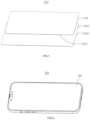
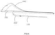
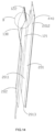
- a first embodiment of the present disclosure provides a sticking film 200, which includes a tempered film 201 and a release film layer 202 attached to the tempered film 201.
- the tempered film 201 is used to be attached to a screen 301 of an electronic product 300, and the release film layer 202 is an electrostatic layer.
- the tempered film 201 is provided with a sticking surface 2011 attached to the release film layer 202. After tearing off the release film layer 202, the sticking surface 2011 is attached to the screen 301 of the electronic product 300.
- the release film layer 202 and the tempered film 201 are separated, and the side of the release film layer 202 that is attached to the tempered film 201 generates static electricity.
- the side of the release film layer 202 with static electricity is placed close to the screen 301 of the electronic product 300 to attract dust on the screen.
- the release film layer 202 is provided with a tip 2021 to facilitate tearing off the release film layer 202.
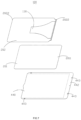
- the sticking film 200 further includes a protective layer 240 disposed on the side of the tempered film 201 away from the sticking surface 2011.
- the tip 2021 is also provided on the protective layer 240 to facilitate tearing off the protective layer 240.
- the release film layer 202 is made of a material that is easy to generate static electricity by friction, so that static electricity is generated when the release film layer 202 and the tempered film 201 are separated.
- the release film layer 202 is made of synthetic-resin-based material, rubber-based material or the like.
- the synthetic-resin-based material includes PET (polyethylene terephthalate), PE (polyethylene), PC (polycarbonate) or PVC (polyvinyl chloride).
- the rubber-based material includes SBR (styrene butadiene rubber), NBR (nitrile butadiene rubber), or some BR (butadiene rubber).
- PET is selected as the material for preparing the release film layer 202.
- the PET material has a wide source, low cost, and excellent material performance.
- the release film layer 202 can be prepared to have different hardnesses according to requirements, so as to prepare different types of the sticking film 200.
- the tempered film 201 has an impact-resisting function, and is mainly obtained by tempering a glass sample made of some silicate material.
- the main material and preparation process thereof are prior art, which will not be repeated here.
- the sticking surface 2011 of the tempered film 201 prepared based on a general process usually includes some glue, such as AB glue, OCA glue or some other polymerized organic compound. Therefore, some of the tempered films 201 are easily with static electricity when separated from the release film layer 202, which will easily cause the tempered film 201 to generate static electricity and attract dust when the release film layer 202 is separated.
- some antistatic materials are added to make the tempered film 201 have antistatic properties, so that when the release film layer 202 is torn off from the tempered film 201, the tempered film 201 will not generate static electricity, which avoids attracting dust and improves the cleanliness of the tempered film 201.
- the sticking film 200 of this embodiment can also complete the pasting without the assistance of a sticking tool.
- An optional film pasting process includes steps of:
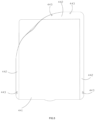
- a second embodiment of the present disclosure provides a sticking film 400, which is different from the sticking film 200 of the first embodiment in that the protective layer 440 includes a covering portion 441 covering the tempered film 201, and a positioning portion 442 extending beyond the covering portion 441.
- the positioning portion 442 is provided with a positioning member 443, which is used to cooperate with the film-sticking tool 500 to position the sticking film 400.
- the positioning member 443 is a through-hole or a pillar.
- the film-sticking tool 500 includes a base 501, which is provided with a positioning slot 502 for accommodating the electronic product 300 to be pasted.
- the base 501 has a first wall 5011 and a second wall 5012 that are oppositely arranged, and the first wall 5011, the second wall 5012 and two side walls 5013 enclose together to form the positioning slot 502.
- the base 501 is provided with a fixing member 5014, which is disposed on the first wall 5011 and the side wall 5013.
- the fixing member 5014 is a pillar.
- the fixing member 5014 is a structure of a through hole, a blind hole or a counterbore.
- An optional film pasting process includes steps of:
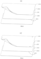
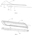
- a third embodiment of the present disclosure provides a sticking film 100, which is mainly different from the sticking film 200 of the first embodiment or the sticking film 400 of the second embodiment in that the sticking film 100 further includes a pulling portion 130 disposed on the release film layer 202, instead of the tip on the release film layer 202, and the release film layer 202 is torn off through the pulling portion 130.
- the release film layer 202 has two end portions 2022 in the longitudinal direction.
- the pulling portion 130 is connected to one end portion 2022 of the release film layer 202, and part or all of the pulling portion 130 is positioned at the side of the release film layer 202 away from the sticking surface 2011.
- the pulling portion 130 extends for a certain length along the longitudinal direction of the release film layer 202.
- the pulling portion 130 is positioned on the release film layer 202 away from the sticking surface 2011 and is pulled toward the free end of the pulling portion 130. At this time, the pulling portion 130 is torn away from the sticking surface 2011 in a folded manner, which can be operated at the top of the screen 301.
- the release film layer 202 can be torn off by pulling the pulling portion 130, the release film 202 is torn off in a folded manner, and the side generating static electricity of the release film layer 202 can be in contact with the screen 301 naturally, so that the dust can be taken away simultaneously, and the use of static electricity can be maximized.
- the release film layer 202 is torn off, the release film layer 202 is positioned between the tempered film 201 and the screen 301 in a curved shape.
- the pulling portion 130 is connected to one end of the release film layer 202 in the width direction.
- the pulling portion 130 extends for a certain length along the width direction of the release film layer 202.
- the release film layer 202 As a film-sticking process, when the release film layer 202 is torn off, the sticking surface 2011 of the release film layer 202 is in pressing contact with the screen 301. In this case, during the process of tearing off the release film layer 202, the release film layer 202 is in contact with the screen 301 and there is friction, so that the release film layer 202 further generates static electricity, and the dust on the screen 301 can be attracted better.
- the release film layer 202 and the pulling portion 130 are integrally formed or separately arranged.
- the release film layer 202 and the pulling portion 130 are required to be connected by means of pasting, clamping, or the like.
- the end of the pulling portion 130 connected with the release film layer 202 is defined as a connecting end 2023.
- the extension length of the pulling portion 130 along the longitudinal direction is greater than the length dimension of the release film layer 202.
- the extension length of the pulling portion 130 along the width direction is greater than the width dimension of the release film layer 202.
- the pulling portion 130 is positioned between the release film layer 202 and the screen 301, and there is a space between the release film layer 202 and the screen 301.
- the release film layer 202 and the tempered film 201 are separated, so that static electricity is generated to attract dust.
- the release film layer 202 can be torn off after placing the electronic product 300, so that the time interval between tearing off the release film layer 202 and attaching the tempered film 201 to the screen is shorter, the operation steps are more consistent, and the time in contact with the air is shortened.
- the process of tearing off and pasting film is almost at the same time, which avoids attracting too much dust and improves the effect of the film sticking.
- the release film layer 202 generates static electricity to attract the dust on the screen 301. That is, the release film layer 202 is torn off in a folded manner by pulling the pulling portion 130, so that the side generating static electricity of the release film layer 202 can be in contact with the screen 301 naturally to attract the dust on the screen 301.
- Way 1 is that during the process of tearing off the release film layer 202, the release film layer 202 is close to instead of in contact with the screen 301, and the static electricity is used to attract dust.
- the tempered film 201 will directly face the screen 301, and the dust on the screen 301 will easily fly to the sticking surface of the tempered film 201.
- Way 2 is that during the process of tearing off the release film layer 202, the release film layer 202 is curled between the screen 301 and the sticking surface 2011 of the tempered film 201, and the release film layer 202 falls on the screen 301 and contacts the screen 301. In this case, when torn off, the release film layer 202 first contacts the screen 301 to attract the dust, so as to prevent the dust from being adsorbed on the tempered film 201.
- the release film layer 202 is in contact with the screen 301, which can well prevent the dust on the area of the screen 301 not covered by the torn release film layer 202 from flying up under the electrostatic attraction of the tempered film 201 and the release film layer 202, resulting in the tempered film 201 also attracting dust.
- the tempered film 201 can be an antistatic layer or a non-antistatic layer.
- the pulling portion 130 and the release film layer 202 are arranged separately, and the pulling portion 130 is connected to the side of the release film layer 202 away from the sticking surface 2011.
- the end of the release film layer 202 and the pulling portion 130 are superimposed to form a step, and the step contacts the screen 301 to remove dust when pulling the pulling portion 130.
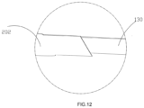
- the tempered film 201 includes a first end 2012 and an opposite second end 2013 in the length direction or the width direction.
- the release film layer 202 includes a sticking portion 121 covering the sticking surface 2011, and a connecting section 122 extending beyond the first end 2012, and the connecting section 122 is connected to the sticking portion 121.
- a folding line 125 is provided to divide the connecting section 122 into a first connecting section 1221 and a second connecting section 1222, which are respectively connected to the sticking portion 121 and the pulling portion 130.
- the folding line 125 extends along the width direction of the tempered film 201; when the connecting section 122 extends beyond the release film layer 202 in the width direction, the folding line 125 extends along the length direction of the tempered film 201. That is, the extension direction of the folding line 125 is perpendicular to that of the connecting section 122.
- the first connecting section 1221 and the second connecting section 1222 are folded along the folding line 125 to form the pulling portion 130 on the side of the release film layer 202 away from the sticking surface 2011, which facilitates pulling and tearing off the release film layer 202.
- the release film layer 202 includes a sticking portion 121 covering the sticking surface 2011 and a connecting section 122 extending beyond the second end 2013. That is, the connecting section 122 is disposed on the side close to the second end 2013.
- the pulling portion 130 By folding the connecting section 122 along the folding line 125, the pulling portion 130 is positioned on the side of the sticking portion 121 away from the tempered film 201, and the extension of the pulling portion 130 exceeds the second end 2013 of the tempered film 201, so that the pulling portion 130 is more convenient to hold and easy to find, the release film layer 202 can be separated from the tempered film 201 only by pulling the pulling portion 130, and the operation is fast.
- the pulling portion 130 is pulled in a direction away from the first end 2012 to make the release film layer 202 gradually separate from the tempered film 201 starting from the first end 2012 of the tempered film 201.
- the sticking surface 2011 of the tempered film 201 is attached to the screen 301 of the electronic product 300 to be pasted to complete the sticking operation.
- the arrangement of the pulling portion 130 makes it simple to separate the release film layer 202 from the tempered film 201, improves the separation rate, and further improves the film-sticking efficiency. It also prevents the user from manually searching for the tear opening of the release film layer 202, causing impurities on the hand to enter the sticking surface 2011 of the tempered film 201, which produces air bubbles between the tempered film 201 and the screen 301, and affects the film-sticking effect.
- the folding line 125 can be formed by a plurality of wire holes or wire grooves arranged at intervals.
- the shape of the wire hole or wire groove can be linear, square, diamond, oval, etc., and the length direction thereof can be consistent with the width direction or the length direction of the tempered film 201.
- the shape of the wire hole or wire groove can also be circular, and the folding line 125 can also be formed by a wire groove extending along the width direction of the tempered film 201.
- the thickness of the wire groove is less than that of the connecting section 122, which can be selected according to actual needs and is not limited here.
- the arrangement of the folding line 125 makes the first connecting section 1221 and the second connecting section 1222 fit more closely after the connecting section 122 is folded.
- the space occupied by the connecting section 122 in the thickness direction of the sticking film 100 is reduced, which facilitates pulling the pulling portion 130.
- the distance between the tempered film 201 and the screen 301 of the electronic product 300 to be pasted is smaller, and the tempered film 201 can be more easily attached to the screen 301 after the pulling portion 130 is pulled.
- the pulling portion 130 is provided with a plurality of storage folding lines 133 that extend along the width direction of the pulling portion 130.
- the storage folding lines 133 are arranged at the M portion of the pulling portion 130 beyond the tempered film 201, and arranged at intervals in the longitudinal direction of the pulling portion 130.
- the storage folding line 133 is formed by a plurality of wire holes arranged at intervals, or formed by at least one wire groove.
- the extension of the pulling portion 130 extends beyond the second end 2013 to facilitate holding and searching.
- the part beyond the tempered film 201 is inconvenient for the sticking film 100 to be stored and packaged before being sold.
- a storage folding line 133 is provided on the pulling portion 130 to facilitate folding the part of the pulling portion 130 of the folded sticking film 100 beyond the second end 2013 of the tempered film 201 toward the first end 2012.
- the storage folding line 133 may be formed by a plurality of wire holes or wire grooves arranged at intervals.
- the shape of the wire hole or wire groove can be linear, square, diamond, oval or the like, and the length direction thereof can be consistent with the width direction or the length direction of the tempered film 201.
- the shape of the wire hole or wire groove may also be circular.
- the storage folding line 133 can also be formed by a wire groove extending along the width direction of the tempered film 201, and the thickness of the wire groove is less than that of the connecting section 122, which can be selected according to actual needs and is not limited here.
- an optional film-sticking process includes steps of:
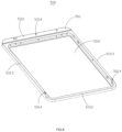
- a fourth embodiment of the present disclosure provides a film-sticking tool 600 for cooperating with the sticking films described in the first, second and third embodiments to attach the tempered film to the screen 301 of the electronic product 300.
- the film-sticking tool 600 includes a base 601, which is provided with a positioning slot 602 for accommodating the electronic product 300 to be filmed.
- the base 601 is provided with a first wall 6011 and a second wall 6012 arranged oppositely, and two side walls 6013 disposed between the first wall 6011 and the second wall 6012.
- the first wall 6011, the second wall 6012 and the two side walls 6013 enclose to define the positioning slot 602.
- a supporting edge 6015 is provided at the corresponding positions of the first wall 6011, the second wall 6012 and the side wall 6013. When the electronic product 300 is placed into the positioning slot 602, the supporting edge 6015 supports and lifts the electronic product 300.
- the film-sticking tool 600 is provided with a pulling opening 6016 through which the pulling portion 130 extends.
- a transition slope can be provided between the side wall 6013 and the second wall 6012, so that the height of the second wall 6012 is lower than that of the side wall 6013 to form the pulling opening 6016.
- the pulling opening 6016 may also be formed in other ways, for example, by opening a through-hole on the second wall 6012 to form the pulling opening 6016.
- the base 601 is provided with a fixing member 6014 for positioning the sticking film.
- the side wall 6013 is configured in a state in which one end in the longitudinal direction is high and the other end therein is low along the extending direction, that is, an inclined state, so that after positioning the sticking film on the film-sticking tool 600 and placing the electronic product 300 in the positioning slot 602, there is a height difference between the height of the first end 2012 of the tempered film 201 relative to the screen 301 and the height of the second end 2013 of the tempered film 201 relative to the screen 301.
- the tempered film at the end with the smaller height difference from the screen is attached to the screen first, and then the tempered film is gradually squeezed along the end with the smaller height difference, so that the direction of the film pasting is fixed, which is further beneficial to remove air bubbles.
- the height difference between the tempered film and the screen may also be configured by other means, for example, the support edge 6015 can be configured to have a structure with a height difference.
- configuring the height difference is not the only way.
- a better film-sticking effect can also be achieved by canceling the height difference to make the height of the first end and the second end consistent to control the process of film sticking from one end to the other end. For example, the direction of the film sticking starts from the end away from the pulling opening 6016, and then gradually attaches toward the end of the pulling opening 6016.
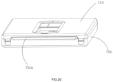
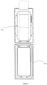
- the film-sticking tool 700 is a film-sticking box.
- the film-sticking tool 700 includes a lower cover 706, an upper cover 703 that can be closed on the lower cover 706, and a base for positioning the electronic product 300.
- the upper cover 703 is disposed opposite to the screen 301 after being closed.
- the base 701 is fixed in the lower cover 706.
- the fixing member 7014 is arranged on the upper cover 703.
- One end of the upper cover 703 and the lower cover 706 are rotatably connected, so that the upper cover 703 can be closed and opened relative to the lower cover 706.
- a cutout is defined at the ends of the upper cover 703 and the lower cover 706 away from the ends where the upper cover 703 is rotatably connected to the lower cover 706 to form a pulling opening 7016.
- the sticking film 100 is positioned on the upper cover 703. After the cover is closed, the tempered film is also configured in an inclined state relative to the screen 301, so as to facilitate the control of the sticking film 100 in a single direction.
- the base 701 can be configured to have a structure with a height difference, so that after the electronic product 300 is placed, there is a height difference between the height of the first end 2012 of the tempered film 201 relative to the screen 301 and the height of the second end 2013 of the tempered film 201 relative to the screen 301.
- the protective layer 440 corresponding to the end with the larger height difference is closely matched with the fixing member 7014, and the protective layer 440 corresponding to the end with the smaller height difference is movably matched with the fixing member 7014.
- the attaching direction of the tempered film can be well controlled, and the tempered film at the end with the smaller height difference is attached to the screen 301 first. Due to the protective layer 440 at the relatively higher end and the fixing member 7014 are relatively closely matched, the protective layer 440 is prevented from falling off automatically, that is, the automatic falling of the tempered film can be prevented, which can well ensure that the tempered film is gradually attached from the end with the smaller height difference to the higher end.
- the end with the smaller height difference is configured to be movably matched, that is, the connection therebetween is relatively loose, which can ensure positioning and alignment, so that the sticking film 100 can be smoothly positioned and aligned with the screen 301 of the electronic product 300. It is avoided that both ends are tightly matched, and the alignment of the sticking film 100 and the screen 301 can be deviated when the manufacturing process is slightly deviated.
- the distance between the end with the lower height difference, the release film layer 202 and the screen 301 is equal to the thickness dimension of the release film layer 202. That is, the inner surface of the upper cover 703, the sticking film 200 and the screen 301 are in contact with each other successively.
- a fifth embodiment of the present disclosure provides a film-sticking assembly 800, which includes the sticking film 200 according to the first embodiment, the sticking film 400 according to the second embodiment or the sticking film 100 according to the third embodiment, and the film-sticking tool 600 or the film-sticking tool 700 according to the fourth embodiment.
- the sticking film can be positioned on the film-sticking tool to complete the sticking of the tempered film of the electronic product.
Landscapes
- Engineering & Computer Science (AREA)
- Manufacturing & Machinery (AREA)
- Chemical & Material Sciences (AREA)
- Organic Chemistry (AREA)
- Laminated Bodies (AREA)
- Adhesive Tapes (AREA)
Applications Claiming Priority (2)
| Application Number | Priority Date | Filing Date | Title |
|---|---|---|---|
| CN202221177877 | 2022-05-16 | ||
| CN202221551563 | 2022-06-20 |
Publications (4)
| Publication Number | Publication Date |
|---|---|
| EP4279250A2 true EP4279250A2 (de) | 2023-11-22 |
| EP4279250A3 EP4279250A3 (de) | 2024-02-28 |
| EP4279250B1 EP4279250B1 (de) | 2026-03-11 |
| EP4279250C0 EP4279250C0 (de) | 2026-03-11 |
Family
ID=83149593
Family Applications (1)
| Application Number | Title | Priority Date | Filing Date |
|---|---|---|---|
| EP22188746.6A Active EP4279250B1 (de) | 2022-05-16 | 2022-08-04 | Klebefilm, filmklebewerkzeug und filmklebeanordnung |
Country Status (3)
| Country | Link |
|---|---|
| US (1) | US11745487B1 (de) |
| EP (1) | EP4279250B1 (de) |
| CN (1) | CN218877704U (de) |
Families Citing this family (4)
| Publication number | Priority date | Publication date | Assignee | Title |
|---|---|---|---|---|
| WO2023217302A2 (zh) * | 2022-05-13 | 2023-11-16 | 东莞市菠萝光电智造有限公司 | 贴膜及贴膜组件 |
| CN117141810A (zh) * | 2023-09-12 | 2023-12-01 | 东莞市创易电子设备有限公司 | 折叠屏保护膜贴膜方法 |
| CN118849412B (zh) * | 2024-07-10 | 2024-12-17 | 西安泽杰隆新材料有限责任公司 | 一种半导体pi胶膜的贴膜装置 |
| CN118991018B (zh) * | 2024-10-22 | 2025-01-28 | 山东明川木业集团有限公司 | 一种用于覆膜胶合板加工的除尘装置 |
Family Cites Families (12)
| Publication number | Priority date | Publication date | Assignee | Title |
|---|---|---|---|---|
| JP4737915B2 (ja) * | 2002-10-30 | 2011-08-03 | 株式会社きもと | タッチパネルの製造方法及びタッチパネル |
| US9902111B2 (en) * | 2013-08-08 | 2018-02-27 | Belkin International, Inc. | Cradle device, method of using the same, and overlay applicator machine |
| US10782746B2 (en) * | 2013-08-08 | 2020-09-22 | Belkin International, Inc. | Overlay for an electronic device |
| WO2015038883A1 (en) | 2013-09-12 | 2015-03-19 | Eshields, Llc | Protective covering applicator for electronic devices |
| CN105766077B (zh) | 2013-10-13 | 2019-07-09 | 贝尔金国际股份有限公司 | 覆盖层敷贴器、敷贴器机器和支架,以及提供和使用它们的方法 |
| CN204750661U (zh) | 2015-06-19 | 2015-11-11 | 王建峰 | 保护膜贴屏定位装置 |
| CN208776649U (zh) * | 2018-08-03 | 2019-04-23 | 深圳市翰博士科技有限公司 | 一种防蓝光的触控屏屏保玻璃 |
| CN213109932U (zh) | 2020-08-13 | 2021-05-04 | 东莞市国基光电有限公司 | 一种屏幕贴膜器 |
| CN112793145A (zh) | 2020-12-07 | 2021-05-14 | 深圳市康成泰实业有限公司 | 贴膜治具及贴膜方法 |
| CN214937163U (zh) * | 2021-03-18 | 2021-11-30 | 深圳市凯卓光电有限公司 | 一种手机丝印防蓝光防静电玻璃钢化膜 |
| CN113428401A (zh) | 2021-07-16 | 2021-09-24 | 深圳市旭艺光电科技有限公司 | 一种快速贴膜辅助装置 |
| CN215972321U (zh) * | 2021-10-14 | 2022-03-08 | 深圳市盾捷商贸有限公司 | 一种贴膜辅助器 |
-
2022
- 2022-07-01 CN CN202221697145.8U patent/CN218877704U/zh not_active Ceased
- 2022-08-02 US US17/878,930 patent/US11745487B1/en active Active
- 2022-08-04 EP EP22188746.6A patent/EP4279250B1/de active Active
Also Published As
| Publication number | Publication date |
|---|---|
| EP4279250B1 (de) | 2026-03-11 |
| EP4279250C0 (de) | 2026-03-11 |
| CN218877704U (zh) | 2023-04-18 |
| US11745487B1 (en) | 2023-09-05 |
| EP4279250A3 (de) | 2024-02-28 |
Similar Documents
| Publication | Publication Date | Title |
|---|---|---|
| US11745487B1 (en) | Sticking film, a film-sticking tool and a film-sticking assembly | |
| CN218877705U (zh) | 贴膜器、贴膜及贴膜组件 | |
| US20200214154A1 (en) | Screen protector and method for applying the same | |
| CN104013181A (zh) | 电子设备保护套 | |
| EP4685061A1 (de) | Klebehilfe, schutzfilmanordnung und filmklebeanordnung | |
| CN220147684U (zh) | 贴膜器、贴膜及贴膜组件 | |
| CN216267609U (zh) | 手机贴膜器 | |
| CN101456463B (zh) | 镜片承载装置 | |
| WO2019007422A1 (zh) | 一种屏幕贴膜装置及多功能包装盒 | |
| CN221163549U (zh) | 贴膜装置 | |
| JP7569567B2 (ja) | 貼付フィルムおよびフィルム貼付アセンブリ | |
| US5445264A (en) | Floppy disk accommodation device | |
| WO2023217302A2 (zh) | 贴膜及贴膜组件 | |
| KR20060094268A (ko) | 컴퓨터 엘시디모니터용 화면보호필름의 가이드케이스및 이를 이용한 부착방법 | |
| CN112829279A (zh) | 贴膜装置及贴膜方法 | |
| TWM653342U (zh) | 貼膜及貼膜組件 | |
| CN218282980U (zh) | 一种具有除尘功能的贴膜装置 | |
| CN217893349U (zh) | 一种贴膜装置 | |
| CN223751341U (zh) | 贴膜盒 | |
| CN219468132U (zh) | 一种贴膜辅助装置 | |
| CN221498575U (zh) | 一种贴膜辅助工具及贴膜套装装置 | |
| CN217146505U (zh) | 保护膜及贴膜组件 | |
| CN217880654U (zh) | 标签架 | |
| CN222757137U (zh) | 一种具备多功能的月饼礼盒 | |
| CN220974677U (zh) | 一种手机贴膜器 |
Legal Events
| Date | Code | Title | Description |
|---|---|---|---|
| PUAI | Public reference made under article 153(3) epc to a published international application that has entered the european phase |
Free format text: ORIGINAL CODE: 0009012 |
|
| STAA | Information on the status of an ep patent application or granted ep patent |
Free format text: STATUS: REQUEST FOR EXAMINATION WAS MADE |
|
| 17P | Request for examination filed |
Effective date: 20220809 |
|
| AK | Designated contracting states |
Kind code of ref document: A2 Designated state(s): AL AT BE BG CH CY CZ DE DK EE ES FI FR GB GR HR HU IE IS IT LI LT LU LV MC MK MT NL NO PL PT RO RS SE SI SK SM TR |
|
| PUAL | Search report despatched |
Free format text: ORIGINAL CODE: 0009013 |
|
| AK | Designated contracting states |
Kind code of ref document: A3 Designated state(s): AL AT BE BG CH CY CZ DE DK EE ES FI FR GB GR HR HU IE IS IT LI LT LU LV MC MK MT NL NO PL PT RO RS SE SI SK SM TR |
|
| RIC1 | Information provided on ipc code assigned before grant |
Ipc: B32B 27/32 20060101ALI20240119BHEP Ipc: B32B 17/06 20060101ALI20240119BHEP Ipc: B29C 63/02 20060101AFI20240119BHEP |
|
| STAA | Information on the status of an ep patent application or granted ep patent |
Free format text: STATUS: EXAMINATION IS IN PROGRESS |
|
| 17Q | First examination report despatched |
Effective date: 20250212 |
|
| GRAP | Despatch of communication of intention to grant a patent |
Free format text: ORIGINAL CODE: EPIDOSNIGR1 |
|
| STAA | Information on the status of an ep patent application or granted ep patent |
Free format text: STATUS: GRANT OF PATENT IS INTENDED |
|
| INTG | Intention to grant announced |
Effective date: 20251009 |
|
| GRAS | Grant fee paid |
Free format text: ORIGINAL CODE: EPIDOSNIGR3 |
|
| GRAA | (expected) grant |
Free format text: ORIGINAL CODE: 0009210 |
|
| STAA | Information on the status of an ep patent application or granted ep patent |
Free format text: STATUS: THE PATENT HAS BEEN GRANTED |
|
| AK | Designated contracting states |
Kind code of ref document: B1 Designated state(s): AL AT BE BG CH CY CZ DE DK EE ES FI FR GB GR HR HU IE IS IT LI LT LU LV MC MK MT NL NO PL PT RO RS SE SI SK SM TR |
|
| REG | Reference to a national code |
Ref country code: CH Ref legal event code: F10 Free format text: ST27 STATUS EVENT CODE: U-0-0-F10-F00 (AS PROVIDED BY THE NATIONAL OFFICE) Effective date: 20260311 Ref country code: GB Ref legal event code: FG4D |
|
| REG | Reference to a national code |
Ref country code: DE Ref legal event code: R096 Ref document number: 602022032001 Country of ref document: DE |
|
| REG | Reference to a national code |
Ref country code: IE Ref legal event code: FG4D |