EP4276247A1 - Soc rabattable pour un dispositif de déblaiement doté d'une lame de brochage - Google Patents
Soc rabattable pour un dispositif de déblaiement doté d'une lame de brochage Download PDFInfo
- Publication number
- EP4276247A1 EP4276247A1 EP23169790.5A EP23169790A EP4276247A1 EP 4276247 A1 EP4276247 A1 EP 4276247A1 EP 23169790 A EP23169790 A EP 23169790A EP 4276247 A1 EP4276247 A1 EP 4276247A1
- Authority
- EP
- European Patent Office
- Prior art keywords
- lever
- folding
- path
- starting position
- pivoting
- Prior art date
- Legal status (The legal status is an assumption and is not a legal conclusion. Google has not performed a legal analysis and makes no representation as to the accuracy of the status listed.)
- Pending
Links
- 230000007246 mechanism Effects 0.000 claims abstract description 41
- 230000000284 resting effect Effects 0.000 claims description 2
- 238000003801 milling Methods 0.000 description 6
- 239000000463 material Substances 0.000 description 5
- 101100116570 Caenorhabditis elegans cup-2 gene Proteins 0.000 description 4
- 101100116572 Drosophila melanogaster Der-1 gene Proteins 0.000 description 4
- 230000001960 triggered effect Effects 0.000 description 4
- 229910000831 Steel Inorganic materials 0.000 description 3
- 230000006835 compression Effects 0.000 description 3
- 238000007906 compression Methods 0.000 description 3
- 239000010959 steel Substances 0.000 description 3
- 229920012196 Polyoxymethylene Copolymer Polymers 0.000 description 2
- 230000003993 interaction Effects 0.000 description 2
- 230000009471 action Effects 0.000 description 1
- 230000005540 biological transmission Effects 0.000 description 1
- 230000015572 biosynthetic process Effects 0.000 description 1
- 230000000903 blocking effect Effects 0.000 description 1
- 238000007664 blowing Methods 0.000 description 1
- 238000011109 contamination Methods 0.000 description 1
- 230000008878 coupling Effects 0.000 description 1
- 238000010168 coupling process Methods 0.000 description 1
- 238000005859 coupling reaction Methods 0.000 description 1
- 238000005336 cracking Methods 0.000 description 1
- 230000006735 deficit Effects 0.000 description 1
- 230000000694 effects Effects 0.000 description 1
- 210000001503 joint Anatomy 0.000 description 1
- 238000007790 scraping Methods 0.000 description 1
- 239000000725 suspension Substances 0.000 description 1
Images


Classifications
-
- E—FIXED CONSTRUCTIONS
- E01—CONSTRUCTION OF ROADS, RAILWAYS, OR BRIDGES
- E01H—STREET CLEANING; CLEANING OF PERMANENT WAYS; CLEANING BEACHES; DISPERSING OR PREVENTING FOG IN GENERAL CLEANING STREET OR RAILWAY FURNITURE OR TUNNEL WALLS
- E01H5/00—Removing snow or ice from roads or like surfaces; Grading or roughening snow or ice
- E01H5/04—Apparatus propelled by animal or engine power; Apparatus propelled by hand with driven dislodging or conveying levelling elements, conveying pneumatically for the dislodged material
- E01H5/06—Apparatus propelled by animal or engine power; Apparatus propelled by hand with driven dislodging or conveying levelling elements, conveying pneumatically for the dislodged material dislodging essentially by non-driven elements, e.g. scraper blades, snow-plough blades, scoop blades
- E01H5/061—Apparatus propelled by animal or engine power; Apparatus propelled by hand with driven dislodging or conveying levelling elements, conveying pneumatically for the dislodged material dislodging essentially by non-driven elements, e.g. scraper blades, snow-plough blades, scoop blades by scraper blades
- E01H5/062—Apparatus propelled by animal or engine power; Apparatus propelled by hand with driven dislodging or conveying levelling elements, conveying pneumatically for the dislodged material dislodging essentially by non-driven elements, e.g. scraper blades, snow-plough blades, scoop blades by scraper blades by scraper blades displaceable for shock-absorbing purposes
-
- E—FIXED CONSTRUCTIONS
- E01—CONSTRUCTION OF ROADS, RAILWAYS, OR BRIDGES
- E01H—STREET CLEANING; CLEANING OF PERMANENT WAYS; CLEANING BEACHES; DISPERSING OR PREVENTING FOG IN GENERAL CLEANING STREET OR RAILWAY FURNITURE OR TUNNEL WALLS
- E01H5/00—Removing snow or ice from roads or like surfaces; Grading or roughening snow or ice
- E01H5/04—Apparatus propelled by animal or engine power; Apparatus propelled by hand with driven dislodging or conveying levelling elements, conveying pneumatically for the dislodged material
- E01H5/08—Apparatus propelled by animal or engine power; Apparatus propelled by hand with driven dislodging or conveying levelling elements, conveying pneumatically for the dislodged material dislodging essentially by driven elements
- E01H5/09—Apparatus propelled by animal or engine power; Apparatus propelled by hand with driven dislodging or conveying levelling elements, conveying pneumatically for the dislodged material dislodging essentially by driven elements the elements being rotary or moving along a closed circular path, e.g. rotary cutter, digging wheels
-
- E—FIXED CONSTRUCTIONS
- E02—HYDRAULIC ENGINEERING; FOUNDATIONS; SOIL SHIFTING
- E02F—DREDGING; SOIL-SHIFTING
- E02F3/00—Dredgers; Soil-shifting machines
- E02F3/04—Dredgers; Soil-shifting machines mechanically-driven
- E02F3/76—Graders, bulldozers, or the like with scraper plates or ploughshare-like elements; Levelling scarifying devices
- E02F3/80—Component parts
- E02F3/815—Blades; Levelling or scarifying tools
- E02F3/8155—Blades; Levelling or scarifying tools provided with movable parts, e.g. cutting discs, vibrating teeth or the like
Definitions
- the invention relates to a folding share for a clearing device with a clearing blade, comprising a folding bar, a lever mechanism for pivotally mounting the folding bar on a base part of the clearing blade and a spring element for arrangement between the base part and the lever mechanism for returning the folding bar to a starting position, in which the folding strip forms an extension of a shield plate of the clearing blade.
- the lever mechanism is designed in such a way that the folding strip can be pivoted along a first pivoting path from the initial position into a pivoted-back position while overcoming a spring force of the spring element, and the folding strip can be pivoted from the pivoted-back position into the initial position due to the spring force along a second pivoting path.
- the invention further relates to a clearing blade with such a lap share.
- Such lap shares are known. They are used in particular in snow clearing machines. However, they are also used for clearing devices for municipal vehicles, rail vehicles or tractors, whereby the clearing devices can be designed as integrated components of the respective vehicles or as interchangeable attachments.
- the snow blower has a large paddle wheel, the axis of which is oriented in the direction of travel. The diameter of the paddle wheel determines the clearing width.
- the rotating blades of the paddle wheel remove the snow from the front and transport it outwards with the help of centrifugal force. The snow is then thrown out through an opening.
- the snow blower has rollers whose axes are oriented at a right angle to the direction of travel. The rollers have reels that are arranged in a spiral around the rollers and run inwards due to the rotational movement. The rotating reels now remove the snow and transport it to the center of the machine. There it is ejected through an opening.
- the snow blower combines these two systems in one machine.
- the milling reels are located in front of it, and the blast wheel is located behind it.
- the milling reels and blast wheel are optimally coordinated with each other through gears and gear ratios in order to be able to work as efficiently as possible.
- This system combines the advantages of the milling reels, which can remove snow better and allow a greater width with a lower overall height, with those of the blower wheel, which enables further ejection with increased snow mass.
- 1 ⁇ lapsshares have one or more folding strips that are pivotally mounted on a base part of the clearing blade.
- the lapping strips are usually designed as wearing parts, as so-called scraping strips. Because they are constantly in contact with the floor area to be cleared during operation, they wear out and have to be replaced when a certain level of wear is reached.
- Such a lap share is available, for example, in snow blowers from the applicant Zaugg AG Eggiwil, Eggiwil, Switzerland, e.g. B. the model SF 7270 I ⁇ S.
- the folding bar is divided in the middle so that the two elements can trigger separately on the left or right, depending on the point at which the obstacle appears.
- Both elements are rotatably mounted on a base part of the clearing blade via a horizontal hinge axis that runs transversely to the direction of travel. When they hit an obstacle, they are pushed backwards.
- the restoring force is provided by a hollow rubber spring, which is installed between the base part and the folding strip is compressed when folded back.
- Other providers also offer snow removal vehicles with similarly designed collision protection, e.g. B. the company Westa GmbH, Weitnau, Germany for their snow blowers types 6570, 7370 and 750.
- 1 ⁇ lapschar systems are also known for snow plows.
- the folding strip forms the lowest section of the plow blade.
- part of the respective foldable assembly moves forward, i.e. H. in the direction of travel. This is not a problem with a snow plow, but corresponding solutions cannot be transferred to snow blowers because the rotating milling reels are in front of the blade and the folding element would collide with them.
- the DE 10 256 541 A1 suggests a mechanism to prevent the 1 ⁇ lapschar from cracking open.
- the corresponding folding bar is guided in such a way that it does not take up any additional space below the base part of the plow blade when it is swiveled back.
- the mechanism creates a virtual pivot axis for the folding bar that lies in front of the plow blade. It includes an i ⁇ double gear with two mutually non-parallel arms or levers and, if necessary, a cam track that serves as a guide during the pivoting movement and can be arranged in a rib or a stiffening plate.
- the mechanism is designed so that the swing back after hitting an obstacle and the return to the starting position takes place along the same predetermined swing path.
- This mechanism improves the swing back of the folding bar after hitting an obstacle.
- problems can still arise, particularly when returning to the starting position, especially if the folding strip comes into contact with the cleared material again during the return, which can lead to the complete return being prevented for a longer period of time. This in turn leads to a deteriorated clearing result.
- the object of the invention is to create a folding share belonging to the technical field mentioned at the beginning, which enables improved return of the folding bar and thus a better clearing result.
- the lever mechanism is designed such that the second pivoting path is different from the first pivoting path.
- the lever mechanism offers at least two degrees of freedom in at least one or more sections of the path between the starting position and the pivoted-back position.
- the sections can extend along the path or be very short in the manner of a switch or branch.
- the two pivoting paths can coincide along one or both end positions, ie only one degree of freedom is present in such a section of the pivoting paths.
- the starting position is characterized in that the folding strip forms an extension of the shield plate of the clearing blade.
- the front main surface of the folding bar in this position lies essentially in the same plane as the front surface of the shield plate along the contact line between the clearing blade and the folding bar.
- the folding strip has a positive swivel angle in this position, i.e. H. its lower free end is at the front in the direction of travel.
- the swiveled back position can be defined by an end stop.
- the folding bar does not have to be swiveled back to this stop every time an obstacle is overcome.
- the reset can take place before the end stop has been reached.
- the lever mechanism should preferably be designed in such a way that different pivoting paths are also provided in this case. This is particularly the case when the first pivoting path and the second pivoting path differ from one another in an area in the vicinity of the starting position. It is particularly preferred that the first pivoting path and the second pivoting path differ at least in a region in which the folding strip assumes a positive pivoting angle.
- a single spring element or several spring elements arranged in series and/or parallel can be used.
- the spring elements are preferably hollow rubber springs. These are insensitive to external influences such as pollution or ice formation, have a long service life and relatively low costs. But there are also other types of tension or compression springs, e.g. B. coil springs, torsion springs or gas pressure springs can be used. In principle, suitably (actively or passively) controlled hydraulic or pneumatic cylinders can also be used as spring elements.
- the spring element or spring elements do not have to be mounted directly on the base part or on the lever mechanism. In particular, the spring element can also be used via transmission means, e.g. B. rods or cables, interact with the lever mechanism.
- the lever mechanism includes pivotally mounted levers. It can also include elements such as guides, stops or cables to control or limit the movement of the levers.
- the basic part of the clearing blade includes the shield plate (the clearing plate) itself and any elements that are firmly connected to the space, such as stiffening plates or profiles, base frames, fastening profiles, etc. Accordingly, the lever mechanism can attack one or more of these elements.
- the lap sharer according to the invention can follow a different pivoting path when returning to the starting position than before when overcoming an obstacle.
- the folding bar When swiveling away from the starting position, the folding bar should move back so that the obstacle can be passed as far as possible without vertical forces on the plow blade and without lifting it.
- the return to the starting position should be as quick and unhindered as possible as soon as the obstacle has been passed.
- the lever mechanism is therefore preferably designed in such a way that when returning from the swung-back position, the lap share first folds forward (i.e. in the direction of travel, in particular until it assumes a positive swivel angle) before it is lowered into the starting position.
- Obstacles up to a certain maximum height can be overcome in this way without the clearing blade popping up and without interrupting the milling operation, and it is ensured that the folding bar returns to its starting position as quickly as possible after overcoming the obstacle and independently while driving, without being disturbed external influences, such as B. contact with the cleared goods to be prevented from returning.
- the 1 ⁇ lapschard according to the invention can also be designed in such a way that all elements of the 1 ⁇ lapschard are arranged above a lower edge of the clearing blade and at the same time completely behind this clearing blade.
- the lever mechanism and the spring element of the 1 ⁇ lapschar according to the invention can be designed to save space, so that conflicts with other elements of the clearing device, e.g. B. a blast wheel, a suspension of the clearing blade or similar can be reliably avoided.
- a lever mechanism can be designed to minimize vibrations after hitting an obstacle.
- the folding strip encloses a first positive angle with a vertical in the starting position. This is in particular in the range 30-60°, in particular 40-50°. In the swung-back position, however, the folding bar assumes a negative angular position so that the obstacle can be passed.
- the second pivoting path therefore advantageously comprises a first path region, adjacent to the pivoted-back position, in which the pivoting path corresponds to a pure pivoting movement about a single axis of rotation, and a second path region in which the pivoting path corresponds to a superposition of two pivoting movements about two spaced axes of rotation.
- the second path area can connect directly to the first path area and extend to the starting position, or there is a further path area between the first path area and the second path area and/or the second path area and the starting position.
- the lever mechanism comprises a never lever, with a first never lever element which is connected in an articulated manner to the base part of the clearing blade and with a second never lever element which is connected in a rotationally fixed manner to the folding bar, the second I ⁇
- the never lever element and the first never lever element are connected to one another in an articulated manner and the spring element acts on the second never lever element.
- Both the first lever element and the second lever element can be connected directly or indirectly to the base part or the folding strip.
- the spring element can act directly or indirectly on the second lever element.
- the folding share can in particular comprise several levers which are arranged parallel to one another and pivotably mount the folding strip on the base part at positions spaced apart in the transverse direction.
- An i ⁇ never lever can be designed to be very robust mechanically, it is cost-effective and its function is less susceptible to external influences such as dirt or icing.
- the never lever requires comparatively little force deflection, so the mechanical loads are low. The deflection occurs smoothly while the folding bar mounted on the never lever is pivoted, so that impact effects on the supported or supported elements are avoided.
- the spring element advantageously acts on the second lever element via a deflection mechanism. This makes it possible in particular to ensure that the spring element can be arranged directly behind the clearing blade to save space, without the direction of the force on the lever mechanism having to be chosen in an unfavorable manner.
- the deflection mechanism preferably comprises a deflection lever rotatably mounted on the base part and a double rod, the spring element and the double rod being mounted at spaced pivot points on the deflection lever and the double rod being connected in an articulated manner to the second double lever element.
- a deflection lever enables the approximately vertical spring force of a spring element arranged behind the clearing blade to save space to be redirected into a force that acts practically horizontally on the second lever element. This enables the folding bar to be reliably reset without the risk of the locking lever becoming blocked after passing the obstacle due to an unfavorable spring force.
- the deflection mechanism can also include a cable pull for redirecting the spring force.
- a combination of spaced compression and tension springs can be used.
- Blocking in the swung-back position can also be achieved using suitable stops, e.g. B. at the middle joint of the I ⁇ never lever.
- suitable stops e.g. B. at the middle joint of the I ⁇ never lever.
- the solution with a lever is more mechanically resilient and less susceptible to contamination or icing.
- the deflection lever, the double rod and the spring element are preferably designed such that a restoring force on the folding bar in the swung-back position is lower than in the starting position. This prevents the folding bar from pivoting back from the starting position due to the force of the material being cleared, while unnecessary resistance when passing an obstacle, i.e. after the pivoting movement has been “triggered”, is prevented.
- a preferred embodiment of the invention comprises a first stop for the first lever element arranged on the base part, with the first lever element resting against the first stop in the swiveled-back position. As long as this contact exists, the lever only has one degree of freedom. If the contact is released after a certain pivoting movement towards the starting position, two degrees of freedom result.
- the lap share includes a second stop arranged on the base part for the second locking lever element, the second stop being designed such that in a section of the second pivoting path, the second locking lever element is guided through an outer contour of the second stop.
- the second lever element can in turn have a specifically shaped outer contour to interact with the outer contour of the second stop, e.g. B. an outer contour which, depending on the rotational position of the second lever element, causes a changing distance between the second stop and the articulation of the spring element and/or the lever joint, i.e. acts as an eccentric.
- the specifically shaped outer contour of the second lever element is in particular convex in shape and is formed on the side of the second lever element facing the second stop.
- both the first stop and the second stop are present, and the first stop limits the second pivoting path in the first travel range, adjacent to the pivoted-back position, to a pure pivoting movement, while the second stop in the second travel range, adjacent to the starting position I ⁇ never lever guides in such a way that two pivoting movements overlap.
- the overlay is in particular such that the folding bar is lowered in the direction of the starting position, in particular while largely maintaining the pivot angle of the folding bar.
- the pivot angle according to the starting position is therefore essentially already reached before the return is completed.
- at least a third of the lowering is carried out in at least a travel area adjacent to the starting position, while the pivot angle in this area is still changed by a maximum of 5°.
- the deflection mechanism and the two stops ensure that the folding strip swings back from the swung-back position and first folds forward again (into a positive angular position) before it sinks again.
- the second stop in the starting position, cooperates with the second lever element in such a way that it prevents movement of the folding strip along the first pivoting path when a force acts on the folding strip from a rear side of a main plane of the folding strip. This avoids in particular that essentially vertical forces, which cannot be caused by an obstacle in the direction of travel, trigger the pivoting movement.
- the 1 ⁇ lapschar is arranged on the clearing blade so that it can be pivoted in such a way that it can be pivoted back from a starting position in which the folding bar of the 1 ⁇ lapschar forms an extension of a shield plate of the clearing blade, into a swung-back position, the folding bar neither during the Pivoting from the starting position into the swung-back position, along the first swivel path, while still swiveling from the swung-back position into the starting position, along the second swivel path, into a path space defined by the clearing blade with the 1 ⁇ lapschar.
- this space corresponds to a space below a level which is defined by the lower edge of the folding strip in the starting position. This prevents the clearing blade from lifting due to vertical forces acting on the folding bar from the ground or from the obstacle.
- the clearing blade preferably has a central receiving opening for a blowing wheel, and a first lap share is arranged on a first side of the receiving opening and a second lap share is arranged on a second side of the receiving opening.
- the folding strips of the first 1 ⁇ lapschar and the second 1 ⁇ lapschar extend into an area below the receiving opening.
- the distance between the folding strips in the transverse direction is advantageously so small that material to be cleared cannot pass between the folding strips in significant quantities when they are in their starting position. In particular, the distance is 5 cm or less.
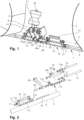
- the Figure 1 shows an oblique view of an exemplary embodiment of the 1 ⁇ lapschar according to the invention, seen laterally from the back.
- the exemplary embodiment relates to a clearing device with a clearing blade width of 220cm, but the illustrated lap share can easily be transferred to larger and smaller clearing blade widths.
- the 1 ⁇ lapschar 1 is arranged on the clearing blade 2 and includes two folding strips 6 made of steel. Visible in the Figure 1 is the right half of the clearing blade up to a central blast wheel housing 3.
- the left side is essentially symmetrical to the right side and includes its own folding strip 6, with the two folding strips 6 in the middle except for a distance in the starting position shown of approx. 5-10 mm.
- the 1 ⁇ lapschar 1 comprises a base part 5, the folding bar 6 and a lever mechanism 10, via which the folding bar 6 is connected to the base part 5 or the clearing blade 2.
- a lever mechanism 10 which is described below in connection with the Figure 2 , is described in more detail, a hollow rubber spring 30, which acts as a compression spring and is pivotably mounted on the clearing blade 2, acts via a spring guide rod 31.
- the spring guide rod 31 presses on an contact roller 41, which is mounted at one end of a deflection lever 40.
- the deflection lever 40 is pivotally mounted on the clearing blade 2 between the bearing plates 7, 8 and comprises two parallel, essentially triangular lever plates 40a, 40b, which are connected to one another via axes in the area of the three corners; the contact roller 41 is mounted on one of these axes. At the end opposite the contact roller 41, the deflection lever 40 is pivotally connected to an coupling rod 45 via an axle 42.
- This is as Steel profile is formed with two bearing tubes welded to each end and acts on the lever mechanism 10, as described in detail below.
- the lever mechanism 10 is shown in the exploded view Fig. 2 described in more detail. It consists largely of steel components. It comprises two lever elements 11, each of which includes two side lever arms 11a, 11b, which are connected to one another via a connecting plate 11c. The connecting plates 11c are screwed to one of two fastening plates 6a welded to the folding strip 6 using several screws. The folding strips 6 can therefore be easily replaced as soon as they are worn out.
- An axle 12 is mounted at the free ends of the lever arms 11a, 11b of each lever element 11.
- a rotating arm 13 is pivotally mounted on the lever element 11 at its first end via this.
- the rotating arm 13 comprises a bearing tube 13a and two lever arms 13b, 13c arranged in a rotationally fixed manner on the bearing tube 13a.
- the bearing tube 13a accommodates the axle 12.
- the lever element 11 and the rotating arm 13 thus form a never lever, the axis 12 forms the axis of rotation of the never lever.
- an axle 14 is mounted on the lever arms 13b, 13c.
- the rotating arm 13 is pivotally mounted on the base part 5 of the 1 ⁇ lapschar 1 via this (see Figs. 3A, 3B ).
- a further axle 46 is mounted, on which the double rod 45 is pivotally mounted.
- the various axes are each accommodated in plain bearings, which are formed by bearing bushes made of a polyoxymethylene copolymer (POM-C).
- FIGS 3A, 3B show a side view of the 1 ⁇ lapschar in the starting position or in the swiveled back position.
- the direction of travel points to the right.
- both the front main surface of the base part 5 and the front main surface of the folding strip 6 lie in the extension of the clearing blade 2. They form an angle of 45 ° with the vertical. For the purposes of this document, this angle is defined as “positive”.
- the hollow rubber spring 30 In the starting position, the hollow rubber spring 30 is in the maximum relaxed position. She pushes the reversing lever 40 diagonally downwards, counterclockwise its end position, which is determined by the stop 55, which interacts with the lever plates of the deflection lever 40.
- the stop 55 can be adjusted using an adjusting screw so that the end position of the lever mechanism 10 and thus the end position of the folding strip 6 can be set in the starting position.
- the double rod 45 acts on the lever element 11 which is firmly connected to the folding strip 6 (see also Figure 5E , where the corresponding linkage can be seen) and pushes it together with the folding strip 6 in the direction of travel.
- the lever element 11 In the starting position, the lever element 11 is oriented practically horizontally, while the second element of the lever, the rotating arm 13 which is pivotally mounted on the base part 5, forms an angle of slightly more than 90° with the lever element 11 and points practically vertically upwards.
- the Figures 4A-4E represent the sequence of movements of the 1 ⁇ lapsshare when swinging back after hitting an obstacle.
- the 1 ⁇ lapsshare 1 typically contacts the obstacle 9 with the lower end of the folding bar 6 ( Figure 4A ).
- the obstacle 9 does not exceed a certain height, 30 mm in the exemplary embodiment shown, it can be driven over without lifting the clearing blade: the folding bar 6 folds back and the obstacle 9 passes under the base part 5 of the 1 ⁇ lapschar that is firmly connected to the clearing blade 2 1.
- the folding back is triggered by the action of the obstacle 9, which initially causes the folding bar 6 to be pivoted clockwise ( Figure 4B ). This means that the lever element 11, which is firmly connected to the folding strip 6, also rotates clockwise around the axis 12.
- the lever element 11 acts on the hollow rubber spring 30 via the double rod 45 and the deflection lever 40 and compresses it.
- the Figs. 5A-5E represent the sequence of movements of the 1 ⁇ lapsshare when returning to the starting position.
- the return occurs due to the spring force of the compressed rubber hollow spring 30. It begins as soon as the force of the obstacle is removed.
- the hollow rubber spring 30 acts on the deflection lever 40 via the spring guide rod 31 and moves it counterclockwise. This leads to a substantially linear pressure force of the double rod 45 on the lever element 11 which is firmly connected to the folding strip 6 ( Figure 5A ). Because the rotary arm 13 rests on the stop 51, this initially leads to a pure rotational movement about the axis 12, so that the folding strip is pivoted counterclockwise towards the starting position.
- the invention is not limited to the exemplary embodiment shown.
- the 1 ⁇ lapschar can have further movable and/or immovable elements.
- the geometry of the levers, the bearings and the spring element can be chosen differently.
- the lever elements that interact with stops can have a specific outer contour in order to control or influence this interaction.
- the invention creates a folding coulter which enables improved return of the folding bar and thus a better clearing result
Landscapes
- Engineering & Computer Science (AREA)
- Civil Engineering (AREA)
- Structural Engineering (AREA)
- Architecture (AREA)
- Mechanical Engineering (AREA)
- Mining & Mineral Resources (AREA)
- General Engineering & Computer Science (AREA)
- Folding Of Thin Sheet-Like Materials, Special Discharging Devices, And Others (AREA)
Applications Claiming Priority (1)
| Application Number | Priority Date | Filing Date | Title |
|---|---|---|---|
| CH000555/2022A CH719686A1 (de) | 2022-05-10 | 2022-05-10 | Klappschar für ein Räumgerät mit einem Räumschild. |
Publications (1)
| Publication Number | Publication Date |
|---|---|
| EP4276247A1 true EP4276247A1 (fr) | 2023-11-15 |
Family
ID=82943172
Family Applications (1)
| Application Number | Title | Priority Date | Filing Date |
|---|---|---|---|
| EP23169790.5A Pending EP4276247A1 (fr) | 2022-05-10 | 2023-04-25 | Soc rabattable pour un dispositif de déblaiement doté d'une lame de brochage |
Country Status (4)
| Country | Link |
|---|---|
| US (1) | US20230366161A1 (fr) |
| EP (1) | EP4276247A1 (fr) |
| CA (1) | CA3199055A1 (fr) |
| CH (1) | CH719686A1 (fr) |
Families Citing this family (1)
| Publication number | Priority date | Publication date | Assignee | Title |
|---|---|---|---|---|
| DK3565928T3 (da) * | 2017-01-05 | 2021-09-06 | 9407 4895 Quebec Inc | Skrabeindretning til rydning af en vejbaneoverflade |
Citations (3)
| Publication number | Priority date | Publication date | Assignee | Title |
|---|---|---|---|---|
| FR2448599A1 (fr) * | 1979-02-07 | 1980-09-05 | Boschung Marcel Ag | Pelle a neige motorisee |
| WO1994029529A1 (fr) * | 1993-06-11 | 1994-12-22 | Gebr. Zaugg Ag | Chasse-neige |
| DE10256541A1 (de) | 2002-12-04 | 2004-07-15 | Fritz Sperber Gmbh & Co. | Räumschild mit schwenkbarer Schürfleiste |
-
2022
- 2022-05-10 CH CH000555/2022A patent/CH719686A1/de unknown
-
2023
- 2023-04-25 EP EP23169790.5A patent/EP4276247A1/fr active Pending
- 2023-05-08 CA CA3199055A patent/CA3199055A1/fr active Pending
- 2023-05-10 US US18/195,440 patent/US20230366161A1/en active Pending
Patent Citations (3)
| Publication number | Priority date | Publication date | Assignee | Title |
|---|---|---|---|---|
| FR2448599A1 (fr) * | 1979-02-07 | 1980-09-05 | Boschung Marcel Ag | Pelle a neige motorisee |
| WO1994029529A1 (fr) * | 1993-06-11 | 1994-12-22 | Gebr. Zaugg Ag | Chasse-neige |
| DE10256541A1 (de) | 2002-12-04 | 2004-07-15 | Fritz Sperber Gmbh & Co. | Räumschild mit schwenkbarer Schürfleiste |
Also Published As
| Publication number | Publication date |
|---|---|
| CH719686A1 (de) | 2023-11-15 |
| CA3199055A1 (fr) | 2023-11-10 |
| US20230366161A1 (en) | 2023-11-16 |
Similar Documents
| Publication | Publication Date | Title |
|---|---|---|
| EP0192940B1 (fr) | Installation de protection contre les tamponnements pour véhicule de transport dans des allées | |
| DE3431327C2 (fr) | ||
| EP1040741B1 (fr) | Outil pour ameublir le sol en profondeur | |
| DE1929177B2 (de) | Strassenraeumgeraet | |
| DE102014009161A1 (de) | Schneidwerk mit Mittelteil und dazu verstellbaren Seitenteilen | |
| EP1927278B1 (fr) | Dispositif de guidage de marchandise dans un appareil agricole | |
| EP4276247A1 (fr) | Soc rabattable pour un dispositif de déblaiement doté d'une lame de brochage | |
| DE4030066C2 (de) | Mähdrescher mit einem zweiteiligen frontseitigen Schneidwerk | |
| EP2532221A1 (fr) | Tondeuse | |
| DE19534695A1 (de) | An einem Schlepper ansetzbares Heckmähwerk | |
| EP2926643A1 (fr) | Machine agricole | |
| DE10012088A1 (de) | Vorrichtung zum Pflücken der Fruchtstände stängeliger Erntegüter | |
| EP1911339B1 (fr) | Char à double disque doté d'un rouleau de guidage en profondeur et accumulateur d'énergie | |
| EP0205854A1 (fr) | Dispositif de transport pour remorque agricole chargeuse | |
| EP1925746B1 (fr) | Dispositif d'entretien de pistes pour un véhicule à chenilles | |
| DE102005018987B4 (de) | Mäh- und/oder Schneidgerät | |
| EP1738634A1 (fr) | Dispositif de ramassage de produits de récolte ainsi que machine de récolte. | |
| DE2807240A1 (de) | Drehpflug | |
| DE202008013786U1 (de) | Mähvorrichtung | |
| EP1557494B1 (fr) | Chasse-neige | |
| EP0842874A2 (fr) | Dispositif séparateur pour installations de stockage dynamique | |
| EP1254593B1 (fr) | Outil pour émietter des sols grossièrement travaillés | |
| AT519380B1 (de) | Schneepflug mit ausweichenden Scharteilen | |
| EP1970492B1 (fr) | Balayeuse avec un dispositif de commande pour ses composants mécaniques | |
| DE1582292B2 (de) | Mähmaschine |
Legal Events
| Date | Code | Title | Description |
|---|---|---|---|
| PUAI | Public reference made under article 153(3) epc to a published international application that has entered the european phase |
Free format text: ORIGINAL CODE: 0009012 |
|
| STAA | Information on the status of an ep patent application or granted ep patent |
Free format text: STATUS: THE APPLICATION HAS BEEN PUBLISHED |
|
| AK | Designated contracting states |
Kind code of ref document: A1 Designated state(s): AL AT BE BG CH CY CZ DE DK EE ES FI FR GB GR HR HU IE IS IT LI LT LU LV MC ME MK MT NL NO PL PT RO RS SE SI SK SM TR |
|
| STAA | Information on the status of an ep patent application or granted ep patent |
Free format text: STATUS: REQUEST FOR EXAMINATION WAS MADE |
|
| 17P | Request for examination filed |
Effective date: 20240212 |
|
| RBV | Designated contracting states (corrected) |
Designated state(s): AL AT BE BG CH CY CZ DE DK EE ES FI FR GB GR HR HU IE IS IT LI LT LU LV MC ME MK MT NL NO PL PT RO RS SE SI SK SM TR |