EP4276156B1 - Verfahren zum verkleben von metallteilen - Google Patents
Verfahren zum verkleben von metallteilen Download PDFInfo
- Publication number
- EP4276156B1 EP4276156B1 EP22173033.6A EP22173033A EP4276156B1 EP 4276156 B1 EP4276156 B1 EP 4276156B1 EP 22173033 A EP22173033 A EP 22173033A EP 4276156 B1 EP4276156 B1 EP 4276156B1
- Authority
- EP
- European Patent Office
- Prior art keywords
- surface portion
- pressurized air
- gas stream
- metal
- metal part
- Prior art date
- Legal status (The legal status is an assumption and is not a legal conclusion. Google has not performed a legal analysis and makes no representation as to the accuracy of the status listed.)
- Active
Links
Images




Classifications
-
- F—MECHANICAL ENGINEERING; LIGHTING; HEATING; WEAPONS; BLASTING
- F16—ENGINEERING ELEMENTS AND UNITS; GENERAL MEASURES FOR PRODUCING AND MAINTAINING EFFECTIVE FUNCTIONING OF MACHINES OR INSTALLATIONS; THERMAL INSULATION IN GENERAL
- F16B—DEVICES FOR FASTENING OR SECURING CONSTRUCTIONAL ELEMENTS OR MACHINE PARTS TOGETHER, e.g. NAILS, BOLTS, CIRCLIPS, CLAMPS, CLIPS OR WEDGES; JOINTS OR JOINTING
- F16B11/00—Connecting constructional elements or machine parts by sticking or pressing them together, e.g. cold pressure welding
- F16B11/006—Connecting constructional elements or machine parts by sticking or pressing them together, e.g. cold pressure welding by gluing
-
- B—PERFORMING OPERATIONS; TRANSPORTING
- B23—MACHINE TOOLS; METAL-WORKING NOT OTHERWISE PROVIDED FOR
- B23K—SOLDERING OR UNSOLDERING; WELDING; CLADDING OR PLATING BY SOLDERING OR WELDING; CUTTING BY APPLYING HEAT LOCALLY, e.g. FLAME CUTTING; WORKING BY LASER BEAM
- B23K26/00—Working by laser beam, e.g. welding, cutting or boring
- B23K26/02—Positioning or observing the workpiece, e.g. with respect to the point of impact; Aligning, aiming or focusing the laser beam
- B23K26/06—Shaping the laser beam, e.g. by masks or multi-focusing
- B23K26/062—Shaping the laser beam, e.g. by masks or multi-focusing by direct control of the laser beam
- B23K26/0622—Shaping the laser beam, e.g. by masks or multi-focusing by direct control of the laser beam by shaping pulses
- B23K26/0624—Shaping the laser beam, e.g. by masks or multi-focusing by direct control of the laser beam by shaping pulses using ultrashort pulses, i.e. pulses of 1 ns or less
-
- B—PERFORMING OPERATIONS; TRANSPORTING
- B23—MACHINE TOOLS; METAL-WORKING NOT OTHERWISE PROVIDED FOR
- B23K—SOLDERING OR UNSOLDERING; WELDING; CLADDING OR PLATING BY SOLDERING OR WELDING; CUTTING BY APPLYING HEAT LOCALLY, e.g. FLAME CUTTING; WORKING BY LASER BEAM
- B23K26/00—Working by laser beam, e.g. welding, cutting or boring
- B23K26/14—Working by laser beam, e.g. welding, cutting or boring using a fluid stream, e.g. a jet of gas, in conjunction with the laser beam; Nozzles therefor
-
- B—PERFORMING OPERATIONS; TRANSPORTING
- B23—MACHINE TOOLS; METAL-WORKING NOT OTHERWISE PROVIDED FOR
- B23K—SOLDERING OR UNSOLDERING; WELDING; CLADDING OR PLATING BY SOLDERING OR WELDING; CUTTING BY APPLYING HEAT LOCALLY, e.g. FLAME CUTTING; WORKING BY LASER BEAM
- B23K26/00—Working by laser beam, e.g. welding, cutting or boring
- B23K26/14—Working by laser beam, e.g. welding, cutting or boring using a fluid stream, e.g. a jet of gas, in conjunction with the laser beam; Nozzles therefor
- B23K26/142—Working by laser beam, e.g. welding, cutting or boring using a fluid stream, e.g. a jet of gas, in conjunction with the laser beam; Nozzles therefor for the removal of by-products
-
- B—PERFORMING OPERATIONS; TRANSPORTING
- B23—MACHINE TOOLS; METAL-WORKING NOT OTHERWISE PROVIDED FOR
- B23K—SOLDERING OR UNSOLDERING; WELDING; CLADDING OR PLATING BY SOLDERING OR WELDING; CUTTING BY APPLYING HEAT LOCALLY, e.g. FLAME CUTTING; WORKING BY LASER BEAM
- B23K26/00—Working by laser beam, e.g. welding, cutting or boring
- B23K26/16—Removal of by-products, e.g. particles or vapours produced during treatment of a workpiece
-
- B—PERFORMING OPERATIONS; TRANSPORTING
- B23—MACHINE TOOLS; METAL-WORKING NOT OTHERWISE PROVIDED FOR
- B23K—SOLDERING OR UNSOLDERING; WELDING; CLADDING OR PLATING BY SOLDERING OR WELDING; CUTTING BY APPLYING HEAT LOCALLY, e.g. FLAME CUTTING; WORKING BY LASER BEAM
- B23K26/00—Working by laser beam, e.g. welding, cutting or boring
- B23K26/352—Working by laser beam, e.g. welding, cutting or boring for surface treatment
-
- B—PERFORMING OPERATIONS; TRANSPORTING
- B23—MACHINE TOOLS; METAL-WORKING NOT OTHERWISE PROVIDED FOR
- B23K—SOLDERING OR UNSOLDERING; WELDING; CLADDING OR PLATING BY SOLDERING OR WELDING; CUTTING BY APPLYING HEAT LOCALLY, e.g. FLAME CUTTING; WORKING BY LASER BEAM
- B23K26/00—Working by laser beam, e.g. welding, cutting or boring
- B23K26/36—Removing material
-
- C—CHEMISTRY; METALLURGY
- C08—ORGANIC MACROMOLECULAR COMPOUNDS; THEIR PREPARATION OR CHEMICAL WORKING-UP; COMPOSITIONS BASED THEREON
- C08J—WORKING-UP; GENERAL PROCESSES OF COMPOUNDING; AFTER-TREATMENT NOT COVERED BY SUBCLASSES C08B, C08C, C08F, C08G or C08H
- C08J5/00—Manufacture of articles or shaped materials containing macromolecular substances
- C08J5/12—Bonding of a preformed macromolecular material to the same or other solid material such as metal, glass, leather, e.g. using adhesives
-
- C—CHEMISTRY; METALLURGY
- C09—DYES; PAINTS; POLISHES; NATURAL RESINS; ADHESIVES; COMPOSITIONS NOT OTHERWISE PROVIDED FOR; APPLICATIONS OF MATERIALS NOT OTHERWISE PROVIDED FOR
- C09J—ADHESIVES; NON-MECHANICAL ASPECTS OF ADHESIVE PROCESSES IN GENERAL; ADHESIVE PROCESSES NOT PROVIDED FOR ELSEWHERE; USE OF MATERIALS AS ADHESIVES
- C09J5/00—Adhesive processes in general; Adhesive processes not provided for elsewhere, e.g. relating to primers
- C09J5/02—Adhesive processes in general; Adhesive processes not provided for elsewhere, e.g. relating to primers involving pretreatment of the surfaces to be joined
-
- F—MECHANICAL ENGINEERING; LIGHTING; HEATING; WEAPONS; BLASTING
- F16—ENGINEERING ELEMENTS AND UNITS; GENERAL MEASURES FOR PRODUCING AND MAINTAINING EFFECTIVE FUNCTIONING OF MACHINES OR INSTALLATIONS; THERMAL INSULATION IN GENERAL
- F16B—DEVICES FOR FASTENING OR SECURING CONSTRUCTIONAL ELEMENTS OR MACHINE PARTS TOGETHER, e.g. NAILS, BOLTS, CIRCLIPS, CLAMPS, CLIPS OR WEDGES; JOINTS OR JOINTING
- F16B7/00—Connections of rods or tubes, e.g. of non-circular section, mutually, including resilient connections
- F16B7/04—Clamping or clipping connections
- F16B7/0406—Clamping or clipping connections for rods or tubes being coaxial
- F16B7/0413—Clamping or clipping connections for rods or tubes being coaxial for tubes using the innerside thereof
-
- A—HUMAN NECESSITIES
- A61—MEDICAL OR VETERINARY SCIENCE; HYGIENE
- A61C—DENTISTRY; APPARATUS OR METHODS FOR ORAL OR DENTAL HYGIENE
- A61C17/00—Devices for cleaning, polishing, rinsing or drying teeth, teeth cavities or prostheses; Saliva removers; Dental appliances for receiving spittle
- A61C17/16—Power-driven cleaning or polishing devices
- A61C17/22—Power-driven cleaning or polishing devices with brushes, cushions, cups, or the like
-
- C—CHEMISTRY; METALLURGY
- C09—DYES; PAINTS; POLISHES; NATURAL RESINS; ADHESIVES; COMPOSITIONS NOT OTHERWISE PROVIDED FOR; APPLICATIONS OF MATERIALS NOT OTHERWISE PROVIDED FOR
- C09J—ADHESIVES; NON-MECHANICAL ASPECTS OF ADHESIVE PROCESSES IN GENERAL; ADHESIVE PROCESSES NOT PROVIDED FOR ELSEWHERE; USE OF MATERIALS AS ADHESIVES
- C09J2400/00—Presence of inorganic and organic materials
- C09J2400/10—Presence of inorganic materials
- C09J2400/16—Metal
- C09J2400/166—Metal in the pretreated surface to be joined
-
- F—MECHANICAL ENGINEERING; LIGHTING; HEATING; WEAPONS; BLASTING
- F16—ENGINEERING ELEMENTS AND UNITS; GENERAL MEASURES FOR PRODUCING AND MAINTAINING EFFECTIVE FUNCTIONING OF MACHINES OR INSTALLATIONS; THERMAL INSULATION IN GENERAL
- F16B—DEVICES FOR FASTENING OR SECURING CONSTRUCTIONAL ELEMENTS OR MACHINE PARTS TOGETHER, e.g. NAILS, BOLTS, CIRCLIPS, CLAMPS, CLIPS OR WEDGES; JOINTS OR JOINTING
- F16B2200/00—Constructional details of connections not covered for in other groups of this subclass
- F16B2200/83—Use of a magnetic material
Definitions
- the present disclosure is concerned with a method of gluing a first metal part to another part such as a second metal part, where at least a surface portion of the first metal part is treated with laser pulses to activate the outer metal surface prior to applying an adhesive.
- a method of gluing a first metal part to another part includes the steps of (a) providing a first metal part such as a steel part, and another part such as a second metal part, (b) treating a surface portion of the first metal part intended for being glued to the other part with laser pulses so that a surface layer of the first metal part across the surface portion is removed, preferably by ablation, (c) while applying laser pulses to the surface portion of the first metal part also applying a pressurized air or gas stream to the surface portion, (d) applying an adhesive to at least the surface portion of the first metal part and/or to a surface of the other part, and (e) gluing the first metal part and the other part together.
- a method of manufacturing a personal care device including the step of gluing a steel shaft into a metal cap, the method comprising the steps of (a) providing the steel shaft and the metal cap sized to receive at least a tip region of the steel shaft, (b) treating a surface portion of the steel shaft intended for being glued to the metal cap with laser pulses so that a surface layer from the steel shaft across the surface portion is removed, preferably by ablation, (c) while treating the surface portion of the steel shaft with the laser pulses also applying a pressurized air or gas stream to the surface portion, (d) treating at least a portion of an inner surface of the metal cap intended for being glued to the respective surface portion of the steel shaft with laser pulses, (e) applying an adhesive to the surface portion of the steel shaft and/or to the portion of the inner surface of the metal cap, and (f) fitting the metal cap onto the steel shaft and curing of the adhesive.
- the metal particles and/or metal ions of the metal vapor thus can eventually redeposit on the just ablated metal surface, which leads to reduction in the purity of the ablated metal surface and thus to a reduced adherence of glue to the re-contaminated metal surface. It was found that such redeposition, while basically relevant for all metal surfaces, becomes specifically troublesome for steel surfaces, which is believed to be due to the chromium content of steel.
- a pressurized air or gas stream is directed to the surface portion of the first metal part that is being treated with laser pulses, e.g., to the surface portion where surface areas are ablated by laser pulses.
- the pressurized air or gas stream tends to carry away the metal vapor and the particulate metal matter that become ejected into the surroundings, i.e., into the treatment volume, from the treated surface portion by the effects of the ablating laser pulses, which, depending on the pulse length and the applied energy may be considered as causing sublimation and melting of surface layers. Due to the sudden sublimation and melting, atoms and particulate matter in the micrometer and sub-micrometer range is catapulted into the treatment volume around the surface portion being treated.
- the gaseous and particulate components may create a plasma that shields the surface portion being treated by laser pulses and some of the laser energy may become absorbed by the plasma and thus the ablation process may become diminished. Further, the particulate matter may impact onto the ablated surface again and may then cause recontamination of the activated metal surface. It was found that recontamination in general and for a first metal part made of steel specifically recontamination comprising chromium causes loosely adhering recontamination areas that may cause breaking points for the glue being applied to the ablated surface.
- adheresive shall mean all adhesives that are suitable for gluing a first metal metal to another part, specifically a second metal part, one example adhesive is DELO DUPOPOX CR8016 available from company DELO Industrie Klebstoffe GmbH & Co. KGaA, Windach, Germany.
- Air or gas stream parameters that were investigated are the following: velocity of the air or gas at the surface portion being treated, velocity of the air or gas at the outlet of a pressure nozzle, distance of the pressure nozzle to the surface portion being treated, amount of air or gas delivered by the pressure nozzle (also known as air flow volume), shape of the pressure nozzle, and orientation and/or position of the pressure nozzle relative to the treated surface portion. These air or gas stream parameters are discussed in more detail in the following.
- Metal particles created in the laser pulse-induced ablation process tend to have velocities that can extend into the sonic and supersonic range, where it is understood that the speed of sound is 343 m/s in air at 20 degrees Celsius.
- a velocity of the pressurized air or gas stream at the surface portion being treated with a laser being in the range of the velocity of the particulate matter in the treatment volume may cause a more prominent reduction of recontamination than velocities being higher or much lower.
- a velocity of the pressurized air or gas stream at the surface portion being treated in a range of between 80 m/s and 400 m/s has been found to be effective.
- the pressurized air or gas stream or jet is typically delivered by a pressurized air or gas delivery system, e.g., a compressed air or gas reservoir.
- the pressurized air or gas stream is typically exiting the pressurized air or gas delivery system via a pressure nozzle. It was also found that a velocity of the pressurized air or gas delivery system at the pressure nozzle may be in a range of between 100 m/s and 700 m/s.
- the pressurized air or gas may have a compression in the range of between 1 bar to 6 bar (these values mean the compression above atmospheric pressure), where the compression may preferably be in a range of between 2 bar and 5 bar.
- the pressurized air or gas stream may be directed towards the surface portion of the first metal part that is being treated with laser pulses.
- a pressure nozzle having an exit shape i.e., the shape of the air or gas outlet
- the pressurized air or gas stream impinging onto the surface portion being treated has about a cross-sectional shape that follows the shape of the surface portion tends to lead to improved adhesion results. It is believed that this can be assigned to a more constant static pressure of the pressurized air or gas stream over the surface portion being treated.
- the static pressure of the pressurized air or gas stream over at least 50% of the surface portion is not deviating from a mean static pressure value in the at least 50% of the surface portion by more than about ⁇ 20%, preferably by more than about ⁇ 15%.
- the surface portion being treated may specifically relate to the length of a laser pulse line.
- the surface portion being treated has a certain area that may be covered by abutting or slightly overlapping laser pulses.
- a single laser pulse may be circular and may have a diameter of 50 ⁇ m and a pulse length in the nanosecond to femtosecond range.
- the pulses may be applied at a frequency of 400 kHz.
- the pulses along a laser line of pulses may then have a center-to-center distance of 20 ⁇ m.
- a line of pulses having a length of 10 mm can thus be applied in 1/800 second. That means that an area of 1.6 mm2 can be treated within a second (ignoring any time that is needed to turn the laser beam, which is typically done by mirrors).
- the surface region being treated has a length extension that is defined by the laser line length.
- a pressurized air or gas stream that covers the full length of the laser line.
- the pressurized air or gas stream may also cover the width of the total surface portion to be treated, but in order to limit the need for pressurized air or gas one can also limit the width of the pressurized air or gas stream and then either the pressurized air or gas stream may be arranged to follow the laser in width direction or the first metal part may be moved to keep the currently being treated surface portion inside the cross-section of the pressurized air or gas stream.
- the first metal part may be rotated so that the currently being treated surface portion stays within the cross-section of the pressurized air or gas stream.
- the width of the pressurized air or gas stream may then be chosen to be larger than the width of the rotating first metal part so that the pressurized air or gas stream can carry metal vapor and particulate matter around the first metal part where the pressurized air or gas stream together with the carried along metal vapor and particulate matter is eventually exhausted by an exhaustion system.
- the pressure nozzle having an air or gas outlet at a distance to the surface portion being treated in the range of between 4 mm and 20 mm, preferably in a range of between 8 mm and 16 mm, where the distance is measured between a central point of the air or gas outlet and a central point of the surface portion. It may be sensible to try to place the pressure nozzle as close to the first metal part as possible as the velocity of the pressurized air or gas stream reduces the longer the distance is.
- the pressure nozzle cannot be placed in the laser path but can be placed at any side with respect to the surface portion being treated, where it may be preferred to place it underneath or above the surface portion being treated, where underneath or above shall mean with respect to the line of laser pulses that is applied onto the surface portion.
- the total surface area to be treated with laser pulses is curved, e.g., if the total surface area is a surface of a metal shaft that circumferentially extends around the shaft, either the laser may be moved around the first metal part or the first metal part may be moved, e.g., rotated. That implies that the pressurized air or gas stream does not need to cover the complete total surface area that is intended to be treated with laser pulses but that it is sufficient to have the pressurized air or gas stream impinge onto the surface portion that is currently being treated.
- the nozzle may have an essentially oval or generally elongated shape, where the long axis of the oval or elongated shape may coincide with the longer extension of the currently being treated surface portion.
- the exhaustion system e.g., a double horn exhaustion system enveloping the treatment area, may have a suction power in a range of between 500 l/min to 3000 l/min, i.e., a suction power that may be higher and even considerably higher than the air flow provided by the pressurized air or gas stream.
- the first metal part is a steel shaft of a personal care device, and the other part is a second metal part, namely a metal cap.
- the steel shaft may be treated by laser pulses on a total surface area that may circumferentially extend around the steel shaft.
- the first metal part in general may be pre-treated first by another method such as plasma pretreatment to immobilize volatile organic compounds on the surface of the metal part.
- a turned and polished metal shaft may still comprise volatile organic compounds on its surface and their immobilization prior to the activation of the metal surface by laser ablation supports keeping the activated surface portion free from contamination. This is of course true for all first metal parts independent from a realization as a steel shaft.
- the steel shaft may be made from a standard stainless steel and may thus comprise a certain percentage of chromium, e.g., more than 10.5% by weight.
- the metal cap may as well be made from a standard stainless steel, specifically in a deep drawing process as is generally known in the art. While an inner surface portion of the metal cap may also be pretreated prior to gluing, e.g., by a plasma pretreatment and/or by a laser pretreatment, this should not be considered mandatory.
- the metal cap is glued onto the tip of the steel shaft and the metal cap may house a further component, e.g., a permanent magnet.
- Table 1 below lists the relevant values for an ultra-fast laser pulse pre-treatment as one example and some ranges are provided that are considered as sensible, even though the below table shall not exclude values outside of the proposed ranges to be used as well. Overall, the values may be varied to some extent if the light fluence stays within the proposed range. It is reiterated that the herein proposed application of a pressurized air or gas stream is also sensible for longer or even shorter laser pulse lengths. Table 1: Example values for an ultra-fast laser pulse pre-treatment of the metal surface and proposed ranges. The various values may be tuned so that the light fluence stays within the proposed range.
- a qualitative test method was developed to investigate the strength of the adhesive connection between the first metal part and the other part and was specifically used to test the strength of the adhesive connection between the steel shaft and the metal cap.
- a hammer was pivotably mounted at an end of its shaft and the hammer was deflected until a predetermined stopper had been reached and then the hammer was released, became accelerated by gravitation, and hit the metal cap/steel shaft element. Between each stroke the metal cap/steel shaft element was rotated around its longitudinal axis by about 20 to 30 degrees.
- the breakage typically appeared at the border between the adhesive and the steel, i.e., once the metal cap could be separated from the steel shaft with a manual force, essentially no adhesive residues adhered to the steel shaft.
- the first metal part 100 is here extending from a complete inner motor chassis intended for insertion onto a housing of a personal care device after another part, namely a metal cap has been glued to the steel shaft.
- a pressure nozzle section 301 of a pressurized air or gas delivery system 300 is provided outside of the path 10 of the laser pulses and directs a pressurized air or gas stream (see Fig. 3 ) via pressure nozzle 310 having an air or gas outlet 311 onto the surface portion 110 of the first metal part 100 that is being treated with laser pulses in operation.
- An air or gas outlet 311 is provided so that the pressurized air or gas stream is directed onto the surface portion 110 being treated.
- the pressurized air or gas stream is directed to the surface portion 110 that is currently being treated with laser pulses, that is the surface portion 110 where metal vapor and particulate matter is being ejected into the treatment volume 190.
- the first metal part 100 may be arranged for being movable, e.g., for being rotatable around its longitudinal axis during the treatment so that the laser can then treat all areas of the total surface portion to be treated.
- the laser beam may also be arranged for having a moving laser beam, where the laser point on the first metal part 100 may be moved in an up and down manner, whereby the laser point may describe a sand-clock type path on the surface portion so that the rotation of the first metal part 100 is compensated and the laser moves along the first metal part 100 in parallel lines.
- the first metal part 100 may also be linearly moved.
- a pressure nozzle 310A having an air or gas outlet 311A is arranged to provide a pressurized air or gas stream that is directed onto the surface portion 110A of the first metal part 100A.
- a cut-out 211A is provided in the first suction horn 210A to provide for a free path area for a laser beam to irradiate the surface portion 110A.
- the pressurized air or gas delivery system 300A (only a nozzle portion is shown here) may and least partly be integral with the first suction horn 210A or may be a separate part that, e.g., may fit into first suction horn 210A.
- Fig. 4 is a depiction of two graphs 401 and 402 indicating the static pressure P S on the surface of a first metal part as shown in Fig. 3 , where with reference to Fig. 3 the static pressure was simulated along a line from the bottom of the surface portion of the first metal part to the tip.
- the graphs 401 and 402 indicate the static pressure along the described line of the cross-sectional cut shown in Fig. 3 . With respect to graph 401 it can be seen in Fig.
- the static pressure P S can be made relatively homogeneous in a larger portion of the surface portion being treated if an exit opening of a pressure nozzle is elongated or oval so that a cross-sectional shape of the pressurized air or gas stream roughly coincides with the shape and specifically the length extension of the surface portion currently being treated with laser pulses.
- This on the one hand serves to direct the pressurized air or gas stream only against the treated surface portion instead of directing the pressurized air or gas stream into an area on the sides, where the energy would be lost without causing an effect.
- This on the other hand serves to avoid recontamination due to air or gas flow from areas experiencing a high static pressure into areas experiencing a low static pressure.
- Graph 420 relates to a circular pressure nozzle that was sized so that the pressurized air or gas stream did not extend beyond the first metal part in a direction perpendicular to the line along which the static pressure was simulated. Hammering tests as described above showed that the adhesive connection endured more hammer strokes when the pressurized air or gas stream caused a static pressure P S as indicated by graph 410.
- Fig. 5A is a SEM picture, where SEM stands for scanning electron microscope, of a metal part surface, specifically of a steel shaft surface, that had been treated with a femtosecond laser to ablate a top layer, where a pressurized air or gas stream was not applied. A scale indicating 500 nm is shown.
- SEM scanning electron microscope
- a metal part surface specifically of a steel shaft surface
- a scale indicating 500 nm is shown.
- Various structures can be seen that are believed to relate to recontamination by particulate matter created in the ablation process. As had been described, it is believed that such recontamination, specifically by metal particles not strongly adhering to the activated metal part surface such as chromium, leads to breaking points for the adhesive connection with an adhesive.
- Fig. 5B is a SEM picture relating to the identical scale of 500 nm of a similar metal part surface, again from a steel shaft, that had been treated with a femtosecond laser to ablate a top layer, where a pressurized air or gas stream was applied during the application of laser pulses.
- the metal surface shows less structures relating to recontamination of the metal surface by particulate matter and vaporized surface material as is visible in Fig. 5A .
- the application of a pressurized air or gas stream caused a surprising effect by what seems to be a reduction of recontamination of the ablated metal surface.
- the effect on the adherence of the glue led to the improvements as described above, namely to a much better adhesive to metal surface connection.
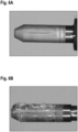
- Fig. 6A is a photographic picture of a steel metal shaft that had been treated with femtosecond laser pulses without application of a pressurized air or gas stream and that had been glued to a metal cap and where the adhesive connection was tested with the hammering method as described above. It can be seen that essentially no macroscopic adhesive residues are left on the metal surface.
- Fig. 6B shows a photographic picture of a steel shaft basically identical to the one shown in Fig. 6A , which steel shaft had also been treated with a femtosecond laser while simultaneously a pressurized air or gas stream as proposed herein was applied. The steel shaft was glued into a metal cap and the adhesive connection was then tested with the hammering method.
- Fig. 7 shows a perspective view onto an example nozzle section 301C of a pressurized air or gas delivery system.
- the view direction is about from a center point on the surface portion being treated on the first metal part in a pretreatment set-up as exemplary shown in Figs. 1 and 2 .
- the nozzle section 301C comprises a pressure nozzle 310C that has an elongated air or gas outlet 311C.
- the pressure nozzle 310C is connected with an essentially circular delivery bore 312C and that the pressure nozzle 311C provides a transition from this circular cross-section into the elongated cross-section of the front of the pressure nozzle 310C, where the cross-section is widened in a length direction and somewhat narrowed in a width direction.
- the cross-sectional shape of the front of the pressure nozzle 310C may here be described as lozenge shaped (i.e., a rectangle with two semi-circles at the small ends of the rectangle).
- the air or gas outlet 311C is shaped so that the pressurized air or gas stream covers the full length of the surface portion to be treated by laser pulses.
- Fig. 8A is a depiction of an example personal care device 50 realized as an electric toothbrush having a handle portion 51 and a treatment head 52, here realized as a replaceable brush head.
- the treatment head 52 comprises in the shown example a functional head 53 that can be driven into an oscillating-rotating motion relative to a housing of the treatment head 52.
- Fig. 8B is a magnification of a part of the personal care device 50 shown in Fig. 8A , where the magnified part is shown in a partly cut open state so that a coupling between a drive shaft 510 of the handle portion 51 with a motion transmitter 520 of the treatment head 52 can be seen.
- the drive shaft 510 is in operation driven into a linear reciprocating motion V, which linear reciprocating motion V is transferred via the motion transmitter 520 to the functional head 53 of the treatment head 52, where the linear reciprocating motion is transferred into an oscillating rotation of the functional head 53.
- the drive shaft 510 may be a steel shaft that had been glued to a metal cap 511.
- a permanent magnet 512 is disposed in the metal cap 511 and an adhesive 513 fills the inner hollow of the metal cap 511.
- the permanent magnet 512 couples with, e.g., a magnetizable steel element 521 that is disposed at the opposing end of the motion transmitter 520.
- the adhesive connection created by the described gluing method durably connects the steel shaft 510 and the metal cap 511 even under the periodic load acting on the metal cap due to the linear reciprocating motion V and also under an aggressive environment formed by toothpaste and saliva. It is understood that the example shown in Figs. 8A and 7B is not limiting the scope of the present disclosure.
Landscapes
- Engineering & Computer Science (AREA)
- Physics & Mathematics (AREA)
- Optics & Photonics (AREA)
- Mechanical Engineering (AREA)
- Plasma & Fusion (AREA)
- General Engineering & Computer Science (AREA)
- Chemical & Material Sciences (AREA)
- Organic Chemistry (AREA)
- Manufacturing & Machinery (AREA)
- Materials Engineering (AREA)
- Health & Medical Sciences (AREA)
- Chemical Kinetics & Catalysis (AREA)
- Medicinal Chemistry (AREA)
- Polymers & Plastics (AREA)
- Laser Beam Processing (AREA)
- Pressure Welding/Diffusion-Bonding (AREA)
- Laminated Bodies (AREA)
- Adhesives Or Adhesive Processes (AREA)
Claims (15)
- Verfahren zum Kleben eines ersten Metallteils an ein anderes Teil, umfassend die Schritte:- Bereitstellen eines ersten Metallteils, wie einen Stahlschaft, und eines weiteren Teils, wie ein zweites Metallteil;- Behandeln eines Oberflächenabschnitts des ersten Metallteils, das bestimmt ist, um an das andere Teil geklebt zu werden, mit Laserimpulsen, sodass eine Oberflächenschicht des ersten Metallteils quer über den Oberflächenabschnitt entfernt wird, vorzugsweise durch Ablation;- während eines Anwendens von Laserimpulsen auf den Oberflächenabschnitt des ersten Metallteils, ebenso Anwenden einer unter Druck gesetzten Luft- oder Gasströmung auf den Oberflächenabschnitt;- Anwenden eines Klebstoffs auf wenigstens den Oberflächenabschnitt des ersten Metallteils und/oder auf eine Oberfläche des anderen Teils; und- Zusammenkleben des ersten Metallteils und des anderen Teils.
- Verfahren nach Anspruch 1, wobei die unter Druck gesetzte Luft- oder Gasströmung an dem Oberflächenabschnitt eine Geschwindigkeit in einem Bereich zwischen 80 m/s und 400 m/s aufweist.
- Verfahren nach Anspruch 1 oder 2, wobei das Luft- oder Gasströmungsvolumen der unter Druck gesetzten Luft- oder Gasströmung in einem Bereich zwischen 50 l/min und 400 l/min liegt.
- Verfahren nach einem der Ansprüche 1 bis 3, wobei ein Winkel zwischen einer Mittellinie der unter Druck gesetzten Luft- oder Gasströmung und einer Mittellinie des Laserimpulses in einem Bereich zwischen 10 Grad und 35 Grad liegt.
- Verfahren nach einem der Ansprüche 1 bis 4, wobei ein statischer Druck der unter Druck gesetzten Luft- oder Gasströmung über wenigstens 50 % des Oberflächenabschnitts von einem durchschnittlichen Wert des statischen Drucks in den wenigstens 50 % des Oberflächenabschnitts um nicht mehr als etwa ±20 % abweicht.
- Verfahren nach einem der Ansprüche 1 bis 5, wobei die unter Druck gesetzte Luft- oder Gasströmung durch eine Druckdüse bereitgestellt wird, die einen Luft- oder Gasauslass aufweist, der einen Abstand zu dem Oberflächenabschnitt in dem Bereich zwischen 4 mm und 20 mm, vorzugsweise in einem Bereich zwischen 8 mm und 16 mm, aufweist, wo der Abstand zwischen einem mittigen Punkt des Luft- oder Gasauslasses und einem mittigen Punkt des Oberflächenabschnitts gemessen wird.
- Verfahren nach Anspruch 6, wobei die Druckdüse eine Form aufweist, sodass eine Querschnittsform der unter Druck gesetzten Luft- oder Gasströmung, die auf den Oberflächenabschnitt des ersten Metallteils auftrifft, in etwa einer Form des Oberflächenabschnitts folgt.
- Verfahren nach Anspruch 6 oder 7, wobei eine Geschwindigkeit der unter Druck gesetzten Luft- oder Gasströmung an dem Luft- oder Gasauslass der Druckdüse in einem Bereich zwischen 100 m/s und 700 m/s liegt.
- Verfahren nach einem der Ansprüche 6 bis 8, wobei die unter Druck gesetzte Luft- oder Gasströmung von einem Druckluft- oder -gasbehälter oder einem Luft- oder Gaskompressor abgegeben wird, wo die Luft oder das Gas in dem Bereich zwischen 1 bar und 6 bar, vorzugsweise in dem Bereich von 2 bar bis 5 bar, komprimiert ist.
- Verfahren nach einem der Ansprüche 1 bis 9, umfassend den Schritt eines Absaugens von Luft und/oder Gas aus einem Behandlungsvolumen mit einer Absaugrate zwischen 500 l/min und 3000 l/min.
- Verfahren nach einem der Ansprüche 1 bis 10, umfassend den Schritt eines Drehens des ersten Metallteils um eine Längserstreckungsachse, wobei sich ein Gesamtoberflächenabschnitt, der bestimmt ist, um an das andere Teil geklebt zu werden, um das erste Metallteil herum in Umfangsrichtung erstreckt.
- Verfahren nach einem der Ansprüche 1 bis 11, wobei die Laserimpulse eine Impulslänge in dem Nanosekunden- bis Femtosekundenbereich aufweisen.
- Verfahren zum Herstellen einer Körperpflegevorrichtung, umfassend den Schritt des Klebens eines Stahlschafts in eine Metallkappe, das Verfahren umfassend die Schritte:- Bereitstellen des Stahlschafts und der Metallkappe, die bemessen ist, um wenigstens eine Spitzenregion des Stahlschafts aufzunehmen;- Behandeln eines Oberflächenabschnitts des Stahlschafts, der bestimmt ist, um an die Metallkappe geklebt zu werden, mit Laserimpulsen, sodass eine Oberflächenschicht von dem Stahlschaft quer über den Oberflächenabschnitt entfernt wird, vorzugsweise durch Ablation;- während des Behandelns des Oberflächenabschnitts des Stahlschafts mit den Laserimpulsen, ebenso Anwenden einer unter Druck gesetzten Luft- oder Gasströmung auf den Oberflächenabschnitt;- Behandeln wenigstens eines Abschnitts einer Innenoberfläche der Metallkappe, die bestimmt ist, um an den jeweiligen Oberflächenabschnitt des Stahlschafts geklebt zu werden, mit Laserimpulsen;- Anwenden eines Klebstoffs auf den Oberflächenabschnitt des Stahlschafts und/oder auf den Abschnitt der Innenoberfläche der Metallkappe; und- Aufsetzen der Metallkappe auf den Stahlschaft und Aushärten des Klebstoffs.
- Verfahren nach Anspruch 13, wobei die unter Druck gesetzte Luft- oder Gasströmung an dem Oberflächenabschnitt eine Geschwindigkeit in einem Bereich zwischen 80 m/s und 400 m/s aufweist.
- Verfahren nach Anspruch 13 oder 14, wobei eine Druckdüse, die die unter Druck gesetzte Luft- oder Gasströmung abgibt, eine Form aufweist, sodass eine Querschnittsform der unter Druck gesetzten Luft- oder Gasströmung, die auf den Oberflächenabschnitt des ersten Metallteils auftrifft, in etwa einer Form des Oberflächenabschnitts folgt.
Priority Applications (7)
| Application Number | Priority Date | Filing Date | Title |
|---|---|---|---|
| EP22173033.6A EP4276156B1 (de) | 2022-05-12 | 2022-05-12 | Verfahren zum verkleben von metallteilen |
| ES22173033T ES3014266T3 (en) | 2022-05-12 | 2022-05-12 | Method of gluing metal parts |
| PCT/IB2023/054792 WO2023218348A1 (en) | 2022-05-12 | 2023-05-09 | Method of gluing metal parts |
| JP2024564815A JP2025516500A (ja) | 2022-05-12 | 2023-05-09 | 金属部品を接着する方法 |
| CN202380039625.6A CN119173596A (zh) | 2022-05-12 | 2023-05-09 | 胶粘金属部件的方法 |
| KR1020247037127A KR20250003727A (ko) | 2022-05-12 | 2023-05-09 | 금속 부품을 접착하는 방법 |
| US18/196,111 US20230366422A1 (en) | 2022-05-12 | 2023-05-11 | Method of gluing metal parts |
Applications Claiming Priority (1)
| Application Number | Priority Date | Filing Date | Title |
|---|---|---|---|
| EP22173033.6A EP4276156B1 (de) | 2022-05-12 | 2022-05-12 | Verfahren zum verkleben von metallteilen |
Publications (2)
| Publication Number | Publication Date |
|---|---|
| EP4276156A1 EP4276156A1 (de) | 2023-11-15 |
| EP4276156B1 true EP4276156B1 (de) | 2025-01-08 |
Family
ID=81648723
Family Applications (1)
| Application Number | Title | Priority Date | Filing Date |
|---|---|---|---|
| EP22173033.6A Active EP4276156B1 (de) | 2022-05-12 | 2022-05-12 | Verfahren zum verkleben von metallteilen |
Country Status (7)
| Country | Link |
|---|---|
| US (1) | US20230366422A1 (de) |
| EP (1) | EP4276156B1 (de) |
| JP (1) | JP2025516500A (de) |
| KR (1) | KR20250003727A (de) |
| CN (1) | CN119173596A (de) |
| ES (1) | ES3014266T3 (de) |
| WO (1) | WO2023218348A1 (de) |
Families Citing this family (1)
| Publication number | Priority date | Publication date | Assignee | Title |
|---|---|---|---|---|
| EP3792323B1 (de) | 2019-09-12 | 2025-12-24 | Braun GmbH | Verfahren zum verkleben von metallteilen |
Family Cites Families (17)
| Publication number | Priority date | Publication date | Assignee | Title |
|---|---|---|---|---|
| JPH07132392A (ja) * | 1993-11-15 | 1995-05-23 | Sumitomo Metal Mining Co Ltd | レーザ加工用ノズル |
| DE19643164C2 (de) * | 1996-10-18 | 1998-09-24 | Lctec Laser Und Computertechni | Vorrichtung und Verfahren zum abtragenden Bearbeiten von Werkstücken mit einem Laserstrahl |
| US20030155328A1 (en) * | 2002-02-15 | 2003-08-21 | Huth Mark C. | Laser micromachining and methods and systems of same |
| JP4775699B2 (ja) * | 2005-09-02 | 2011-09-21 | 日立金属株式会社 | レーザによる両面溝加工装置及び両面溝加工方法 |
| EP2253413A1 (de) * | 2009-05-15 | 2010-11-24 | National University of Ireland Galway | Laserablationsverfahren |
| JP5340447B2 (ja) * | 2012-03-28 | 2013-11-13 | 日東電工株式会社 | レーザー加工方法及びレーザー加工品 |
| JP6196059B2 (ja) * | 2013-04-10 | 2017-09-13 | 株式会社ディスコ | レーザー加工装置 |
| DE102013215346B4 (de) * | 2013-08-05 | 2017-12-07 | Trumpf Laser- Und Systemtechnik Gmbh | Verfahren zum Laserentschichten von beschichteten Blechen und zugehörige Laserentschichtungsanlage |
| JP6496536B2 (ja) * | 2014-12-05 | 2019-04-03 | ダイセルポリマー株式会社 | 軸一体型歯車とその製造方法 |
| CN109153096B (zh) * | 2016-05-23 | 2021-11-05 | 松下知识产权经营株式会社 | 激光焊接装置及激光焊接方法 |
| JPWO2018181526A1 (ja) * | 2017-03-31 | 2020-02-06 | ダイセルポリマー株式会社 | 医療器具とその製造方法 |
| KR102379215B1 (ko) * | 2017-10-31 | 2022-03-28 | 삼성디스플레이 주식회사 | 레이저 장치 |
| US12083625B2 (en) * | 2019-04-05 | 2024-09-10 | Rtx Corporation | Laser surface treatment on stainless steel and nickel alloys for adhesive bonding |
| JP7268500B2 (ja) * | 2019-06-25 | 2023-05-08 | オムロン株式会社 | 接合構造体 |
| JP7307614B2 (ja) * | 2019-07-09 | 2023-07-12 | 日鉄テックスエンジ株式会社 | 下地処理方法及び下地処理装置 |
| EP3792323B1 (de) | 2019-09-12 | 2025-12-24 | Braun GmbH | Verfahren zum verkleben von metallteilen |
| US11578604B2 (en) * | 2020-03-17 | 2023-02-14 | Raytheon Technologies Corporation | Adhesive bonded composite-to-metal hybrid vanes and method of manufacture |
-
2022
- 2022-05-12 EP EP22173033.6A patent/EP4276156B1/de active Active
- 2022-05-12 ES ES22173033T patent/ES3014266T3/es active Active
-
2023
- 2023-05-09 WO PCT/IB2023/054792 patent/WO2023218348A1/en not_active Ceased
- 2023-05-09 KR KR1020247037127A patent/KR20250003727A/ko active Pending
- 2023-05-09 JP JP2024564815A patent/JP2025516500A/ja active Pending
- 2023-05-09 CN CN202380039625.6A patent/CN119173596A/zh active Pending
- 2023-05-11 US US18/196,111 patent/US20230366422A1/en active Pending
Also Published As
| Publication number | Publication date |
|---|---|
| EP4276156A1 (de) | 2023-11-15 |
| WO2023218348A1 (en) | 2023-11-16 |
| CN119173596A (zh) | 2024-12-20 |
| KR20250003727A (ko) | 2025-01-07 |
| US20230366422A1 (en) | 2023-11-16 |
| JP2025516500A (ja) | 2025-05-30 |
| ES3014266T3 (en) | 2025-04-21 |
Similar Documents
| Publication | Publication Date | Title |
|---|---|---|
| EP4276156A1 (de) | Verfahren zum verkleben von metallteilen | |
| TWI593498B (zh) | 雷射加工裝置 | |
| WO2013002165A1 (ja) | 脆性的な部材を切断する装置、方法、および切断された脆性的な部材 | |
| JP2000117481A (ja) | レーザ溶接装置 | |
| KR20000022244A (ko) | 레이저빔에 의한 공동 글래스 물품 절단 방법 및 장치 | |
| US12117027B2 (en) | Method of gluing metal parts | |
| JPH08141764A (ja) | レーザ切断方法 | |
| KR101735006B1 (ko) | 강선 표면 세정 장치 및 세정 방법 | |
| US10365479B2 (en) | Protection of laser bond inspection optical components | |
| JPH11780A (ja) | レーザ・ウォータジェット複合切断装置 | |
| JP2005088068A (ja) | レーザ加工装置及びレーザ加工工法 | |
| JP4478251B2 (ja) | レーザとウォータジェットの複合加工装置 | |
| JPWO2001089843A1 (ja) | ヘッド部材及び撥インク処理方法並びに処理装置 | |
| JP4036387B2 (ja) | レーザアシスト高速フレーム溶射法および装置 | |
| EP1971448B1 (de) | Verfahren und vorrichtung zur behandlung einer oberfläche um diese von verunreinigungen zu befreien | |
| JP2022500335A (ja) | 脆性材料で構成された構造物の切断方法および装置 | |
| JP2000054105A (ja) | 表面の前処理および被覆方法 | |
| JPH11774A (ja) | レーザ・ウォータジェット複合切断方法及び装置 | |
| KR20180097373A (ko) | 노즐을 이용한 금속 자재의 가공장치 및 가공방법 | |
| JP2004223639A (ja) | 薄膜構造物加工装置 | |
| CN118369177A (zh) | 用于通过大气压等离子体束和激光束的组合加工工件表面的设备 | |
| JP2022091009A (ja) | スクリーン枠の付着物除去方法、及び付着物除去装置 | |
| JPH09216081A (ja) | レーザ切断装置 | |
| JPH11787A (ja) | 加圧水中レーザ・ウォータジェット複合切断装置 | |
| KR102572169B1 (ko) | 이동수단에 탑재된 상태에서 표면 처리를 수행하는 레이저 블라스트 공법 |
Legal Events
| Date | Code | Title | Description |
|---|---|---|---|
| PUAI | Public reference made under article 153(3) epc to a published international application that has entered the european phase |
Free format text: ORIGINAL CODE: 0009012 |
|
| STAA | Information on the status of an ep patent application or granted ep patent |
Free format text: STATUS: THE APPLICATION HAS BEEN PUBLISHED |
|
| AK | Designated contracting states |
Kind code of ref document: A1 Designated state(s): AL AT BE BG CH CY CZ DE DK EE ES FI FR GB GR HR HU IE IS IT LI LT LU LV MC MK MT NL NO PL PT RO RS SE SI SK SM TR |
|
| STAA | Information on the status of an ep patent application or granted ep patent |
Free format text: STATUS: REQUEST FOR EXAMINATION WAS MADE |
|
| 17P | Request for examination filed |
Effective date: 20240416 |
|
| RBV | Designated contracting states (corrected) |
Designated state(s): AL AT BE BG CH CY CZ DE DK EE ES FI FR GB GR HR HU IE IS IT LI LT LU LV MC MK MT NL NO PL PT RO RS SE SI SK SM TR |
|
| GRAP | Despatch of communication of intention to grant a patent |
Free format text: ORIGINAL CODE: EPIDOSNIGR1 |
|
| STAA | Information on the status of an ep patent application or granted ep patent |
Free format text: STATUS: GRANT OF PATENT IS INTENDED |
|
| RIC1 | Information provided on ipc code assigned before grant |
Ipc: B23K 26/16 20060101ALI20240802BHEP Ipc: F16B 7/04 20060101ALI20240802BHEP Ipc: B23K 26/0622 20140101ALI20240802BHEP Ipc: B23K 26/142 20140101ALI20240802BHEP Ipc: F16B 11/00 20060101ALI20240802BHEP Ipc: A61C 17/22 20060101ALI20240802BHEP Ipc: C08J 5/12 20060101ALI20240802BHEP Ipc: B29C 65/48 20060101ALI20240802BHEP Ipc: C23C 18/20 20060101ALI20240802BHEP Ipc: B23K 26/36 20140101ALI20240802BHEP Ipc: C09J 5/02 20060101AFI20240802BHEP |
|
| INTG | Intention to grant announced |
Effective date: 20240828 |
|
| P01 | Opt-out of the competence of the unified patent court (upc) registered |
Free format text: CASE NUMBER: APP_49186/2024 Effective date: 20240829 |
|
| GRAS | Grant fee paid |
Free format text: ORIGINAL CODE: EPIDOSNIGR3 |
|
| GRAA | (expected) grant |
Free format text: ORIGINAL CODE: 0009210 |
|
| STAA | Information on the status of an ep patent application or granted ep patent |
Free format text: STATUS: THE PATENT HAS BEEN GRANTED |
|
| AK | Designated contracting states |
Kind code of ref document: B1 Designated state(s): AL AT BE BG CH CY CZ DE DK EE ES FI FR GB GR HR HU IE IS IT LI LT LU LV MC MK MT NL NO PL PT RO RS SE SI SK SM TR |
|
| REG | Reference to a national code |
Ref country code: GB Ref legal event code: FG4D |
|
| REG | Reference to a national code |
Ref country code: CH Ref legal event code: EP |
|
| REG | Reference to a national code |
Ref country code: DE Ref legal event code: R096 Ref document number: 602022009493 Country of ref document: DE |
|
| REG | Reference to a national code |
Ref country code: IE Ref legal event code: FG4D |
|
| REG | Reference to a national code |
Ref country code: NL Ref legal event code: FP |
|
| REG | Reference to a national code |
Ref country code: SE Ref legal event code: TRGR |
|
| REG | Reference to a national code |
Ref country code: ES Ref legal event code: FG2A Ref document number: 3014266 Country of ref document: ES Kind code of ref document: T3 Effective date: 20250421 |
|
| REG | Reference to a national code |
Ref country code: LT Ref legal event code: MG9D |
|
| PGFP | Annual fee paid to national office [announced via postgrant information from national office to epo] |
Ref country code: NL Payment date: 20250409 Year of fee payment: 4 |
|
| REG | Reference to a national code |
Ref country code: AT Ref legal event code: MK05 Ref document number: 1758333 Country of ref document: AT Kind code of ref document: T Effective date: 20250108 |
|
| PG25 | Lapsed in a contracting state [announced via postgrant information from national office to epo] |
Ref country code: RS Free format text: LAPSE BECAUSE OF FAILURE TO SUBMIT A TRANSLATION OF THE DESCRIPTION OR TO PAY THE FEE WITHIN THE PRESCRIBED TIME-LIMIT Effective date: 20250408 |
|
| PG25 | Lapsed in a contracting state [announced via postgrant information from national office to epo] |
Ref country code: PL Free format text: LAPSE BECAUSE OF FAILURE TO SUBMIT A TRANSLATION OF THE DESCRIPTION OR TO PAY THE FEE WITHIN THE PRESCRIBED TIME-LIMIT Effective date: 20250108 |
|
| PGFP | Annual fee paid to national office [announced via postgrant information from national office to epo] |
Ref country code: DE Payment date: 20250402 Year of fee payment: 4 |
|
| PGFP | Annual fee paid to national office [announced via postgrant information from national office to epo] |
Ref country code: ES Payment date: 20250605 Year of fee payment: 4 |
|
| PG25 | Lapsed in a contracting state [announced via postgrant information from national office to epo] |
Ref country code: NO Free format text: LAPSE BECAUSE OF FAILURE TO SUBMIT A TRANSLATION OF THE DESCRIPTION OR TO PAY THE FEE WITHIN THE PRESCRIBED TIME-LIMIT Effective date: 20250408 Ref country code: IS Free format text: LAPSE BECAUSE OF FAILURE TO SUBMIT A TRANSLATION OF THE DESCRIPTION OR TO PAY THE FEE WITHIN THE PRESCRIBED TIME-LIMIT Effective date: 20250508 |
|
| PG25 | Lapsed in a contracting state [announced via postgrant information from national office to epo] |
Ref country code: HR Free format text: LAPSE BECAUSE OF FAILURE TO SUBMIT A TRANSLATION OF THE DESCRIPTION OR TO PAY THE FEE WITHIN THE PRESCRIBED TIME-LIMIT Effective date: 20250108 |
|
| PG25 | Lapsed in a contracting state [announced via postgrant information from national office to epo] |
Ref country code: LV Free format text: LAPSE BECAUSE OF FAILURE TO SUBMIT A TRANSLATION OF THE DESCRIPTION OR TO PAY THE FEE WITHIN THE PRESCRIBED TIME-LIMIT Effective date: 20250108 Ref country code: PT Free format text: LAPSE BECAUSE OF FAILURE TO SUBMIT A TRANSLATION OF THE DESCRIPTION OR TO PAY THE FEE WITHIN THE PRESCRIBED TIME-LIMIT Effective date: 20250508 |
|
| PGFP | Annual fee paid to national office [announced via postgrant information from national office to epo] |
Ref country code: FR Payment date: 20250401 Year of fee payment: 4 |
|
| PG25 | Lapsed in a contracting state [announced via postgrant information from national office to epo] |
Ref country code: GR Free format text: LAPSE BECAUSE OF FAILURE TO SUBMIT A TRANSLATION OF THE DESCRIPTION OR TO PAY THE FEE WITHIN THE PRESCRIBED TIME-LIMIT Effective date: 20250409 Ref country code: BG Free format text: LAPSE BECAUSE OF FAILURE TO SUBMIT A TRANSLATION OF THE DESCRIPTION OR TO PAY THE FEE WITHIN THE PRESCRIBED TIME-LIMIT Effective date: 20250108 |
|
| PGFP | Annual fee paid to national office [announced via postgrant information from national office to epo] |
Ref country code: CH Payment date: 20250601 Year of fee payment: 4 |
|
| PG25 | Lapsed in a contracting state [announced via postgrant information from national office to epo] |
Ref country code: AT Free format text: LAPSE BECAUSE OF FAILURE TO SUBMIT A TRANSLATION OF THE DESCRIPTION OR TO PAY THE FEE WITHIN THE PRESCRIBED TIME-LIMIT Effective date: 20250108 |
|
| PGFP | Annual fee paid to national office [announced via postgrant information from national office to epo] |
Ref country code: SE Payment date: 20250411 Year of fee payment: 4 |
|
| PG25 | Lapsed in a contracting state [announced via postgrant information from national office to epo] |
Ref country code: SM Free format text: LAPSE BECAUSE OF FAILURE TO SUBMIT A TRANSLATION OF THE DESCRIPTION OR TO PAY THE FEE WITHIN THE PRESCRIBED TIME-LIMIT Effective date: 20250108 |
|
| REG | Reference to a national code |
Ref country code: DE Ref legal event code: R097 Ref document number: 602022009493 Country of ref document: DE |
|
| PG25 | Lapsed in a contracting state [announced via postgrant information from national office to epo] |
Ref country code: DK Free format text: LAPSE BECAUSE OF FAILURE TO SUBMIT A TRANSLATION OF THE DESCRIPTION OR TO PAY THE FEE WITHIN THE PRESCRIBED TIME-LIMIT Effective date: 20250108 |
|
| PG25 | Lapsed in a contracting state [announced via postgrant information from national office to epo] |
Ref country code: EE Free format text: LAPSE BECAUSE OF FAILURE TO SUBMIT A TRANSLATION OF THE DESCRIPTION OR TO PAY THE FEE WITHIN THE PRESCRIBED TIME-LIMIT Effective date: 20250108 Ref country code: CZ Free format text: LAPSE BECAUSE OF FAILURE TO SUBMIT A TRANSLATION OF THE DESCRIPTION OR TO PAY THE FEE WITHIN THE PRESCRIBED TIME-LIMIT Effective date: 20250108 |
|
| PG25 | Lapsed in a contracting state [announced via postgrant information from national office to epo] |
Ref country code: RO Free format text: LAPSE BECAUSE OF FAILURE TO SUBMIT A TRANSLATION OF THE DESCRIPTION OR TO PAY THE FEE WITHIN THE PRESCRIBED TIME-LIMIT Effective date: 20250108 |
|
| PG25 | Lapsed in a contracting state [announced via postgrant information from national office to epo] |
Ref country code: SK Free format text: LAPSE BECAUSE OF FAILURE TO SUBMIT A TRANSLATION OF THE DESCRIPTION OR TO PAY THE FEE WITHIN THE PRESCRIBED TIME-LIMIT Effective date: 20250108 |
|
| PLBE | No opposition filed within time limit |
Free format text: ORIGINAL CODE: 0009261 |
|
| STAA | Information on the status of an ep patent application or granted ep patent |
Free format text: STATUS: NO OPPOSITION FILED WITHIN TIME LIMIT |
|
| 26N | No opposition filed |
Effective date: 20251009 |
|
| PGFP | Annual fee paid to national office [announced via postgrant information from national office to epo] |
Ref country code: IT Payment date: 20250531 Year of fee payment: 4 |
|
| PG25 | Lapsed in a contracting state [announced via postgrant information from national office to epo] |
Ref country code: LU Free format text: LAPSE BECAUSE OF NON-PAYMENT OF DUE FEES Effective date: 20250512 |
|
| REG | Reference to a national code |
Ref country code: BE Ref legal event code: MM Effective date: 20250531 |
|
| PG25 | Lapsed in a contracting state [announced via postgrant information from national office to epo] |
Ref country code: MC Free format text: LAPSE BECAUSE OF FAILURE TO SUBMIT A TRANSLATION OF THE DESCRIPTION OR TO PAY THE FEE WITHIN THE PRESCRIBED TIME-LIMIT Effective date: 20250108 |
|
| PGFP | Annual fee paid to national office [announced via postgrant information from national office to epo] |
Ref country code: GB Payment date: 20260313 Year of fee payment: 5 |
|
| PG25 | Lapsed in a contracting state [announced via postgrant information from national office to epo] |
Ref country code: IE Free format text: LAPSE BECAUSE OF NON-PAYMENT OF DUE FEES Effective date: 20250512 |
|
| PG25 | Lapsed in a contracting state [announced via postgrant information from national office to epo] |
Ref country code: BE Free format text: LAPSE BECAUSE OF NON-PAYMENT OF DUE FEES Effective date: 20250531 |