EP4274792B1 - Agencement de machine comprenant une pluralité de stations de traitement, chacune traitant des substrats sous forme de feuilles - Google Patents
Agencement de machine comprenant une pluralité de stations de traitement, chacune traitant des substrats sous forme de feuilles Download PDFInfo
- Publication number
- EP4274792B1 EP4274792B1 EP22737434.5A EP22737434A EP4274792B1 EP 4274792 B1 EP4274792 B1 EP 4274792B1 EP 22737434 A EP22737434 A EP 22737434A EP 4274792 B1 EP4274792 B1 EP 4274792B1
- Authority
- EP
- European Patent Office
- Prior art keywords
- suction belt
- belt table
- substrates
- sheets
- transport
- Prior art date
- Legal status (The legal status is an assumption and is not a legal conclusion. Google has not performed a legal analysis and makes no representation as to the accuracy of the status listed.)
- Active
Links
Images


Classifications
-
- B—PERFORMING OPERATIONS; TRANSPORTING
- B65—CONVEYING; PACKING; STORING; HANDLING THIN OR FILAMENTARY MATERIAL
- B65H—HANDLING THIN OR FILAMENTARY MATERIAL, e.g. SHEETS, WEBS, CABLES
- B65H11/00—Feed tables
- B65H11/002—Feed tables incorporating transport belts
- B65H11/005—Suction belts
-
- B—PERFORMING OPERATIONS; TRANSPORTING
- B41—PRINTING; LINING MACHINES; TYPEWRITERS; STAMPS
- B41F—PRINTING MACHINES OR PRESSES
- B41F13/00—Common details of rotary presses or machines
- B41F13/54—Auxiliary folding, cutting, collecting or depositing of sheets or webs
- B41F13/64—Collecting
-
- B—PERFORMING OPERATIONS; TRANSPORTING
- B41—PRINTING; LINING MACHINES; TYPEWRITERS; STAMPS
- B41F—PRINTING MACHINES OR PRESSES
- B41F19/00—Apparatus or machines for carrying out printing operations combined with other operations
- B41F19/001—Apparatus or machines for carrying out printing operations combined with other operations with means for coating or laminating
-
- B—PERFORMING OPERATIONS; TRANSPORTING
- B41—PRINTING; LINING MACHINES; TYPEWRITERS; STAMPS
- B41F—PRINTING MACHINES OR PRESSES
- B41F19/00—Apparatus or machines for carrying out printing operations combined with other operations
- B41F19/007—Apparatus or machines for carrying out printing operations combined with other operations with selective printing mechanisms, e.g. ink-jet or thermal printers
-
- B—PERFORMING OPERATIONS; TRANSPORTING
- B41—PRINTING; LINING MACHINES; TYPEWRITERS; STAMPS
- B41F—PRINTING MACHINES OR PRESSES
- B41F21/00—Devices for conveying sheets through printing apparatus or machines
-
- B—PERFORMING OPERATIONS; TRANSPORTING
- B41—PRINTING; LINING MACHINES; TYPEWRITERS; STAMPS
- B41F—PRINTING MACHINES OR PRESSES
- B41F23/00—Devices for treating the surfaces of sheets, webs, or other articles in connection with printing
- B41F23/04—Devices for treating the surfaces of sheets, webs, or other articles in connection with printing by heat drying, by cooling, by applying powders
- B41F23/044—Drying sheets, e.g. between two printing stations
- B41F23/045—Drying sheets, e.g. between two printing stations by radiation
- B41F23/0453—Drying sheets, e.g. between two printing stations by radiation by ultraviolet dryers
-
- B—PERFORMING OPERATIONS; TRANSPORTING
- B41—PRINTING; LINING MACHINES; TYPEWRITERS; STAMPS
- B41F—PRINTING MACHINES OR PRESSES
- B41F23/00—Devices for treating the surfaces of sheets, webs, or other articles in connection with printing
- B41F23/04—Devices for treating the surfaces of sheets, webs, or other articles in connection with printing by heat drying, by cooling, by applying powders
- B41F23/044—Drying sheets, e.g. between two printing stations
- B41F23/045—Drying sheets, e.g. between two printing stations by radiation
- B41F23/0456—Drying sheets, e.g. between two printing stations by radiation by infrared dryers
-
- B—PERFORMING OPERATIONS; TRANSPORTING
- B41—PRINTING; LINING MACHINES; TYPEWRITERS; STAMPS
- B41F—PRINTING MACHINES OR PRESSES
- B41F23/00—Devices for treating the surfaces of sheets, webs, or other articles in connection with printing
- B41F23/04—Devices for treating the surfaces of sheets, webs, or other articles in connection with printing by heat drying, by cooling, by applying powders
- B41F23/044—Drying sheets, e.g. between two printing stations
- B41F23/0463—Drying sheets, e.g. between two printing stations by convection
- B41F23/0466—Drying sheets, e.g. between two printing stations by convection by using heated air
-
- B—PERFORMING OPERATIONS; TRANSPORTING
- B41—PRINTING; LINING MACHINES; TYPEWRITERS; STAMPS
- B41F—PRINTING MACHINES OR PRESSES
- B41F23/00—Devices for treating the surfaces of sheets, webs, or other articles in connection with printing
- B41F23/04—Devices for treating the surfaces of sheets, webs, or other articles in connection with printing by heat drying, by cooling, by applying powders
- B41F23/0476—Cooling
-
- B—PERFORMING OPERATIONS; TRANSPORTING
- B41—PRINTING; LINING MACHINES; TYPEWRITERS; STAMPS
- B41F—PRINTING MACHINES OR PRESSES
- B41F23/00—Devices for treating the surfaces of sheets, webs, or other articles in connection with printing
- B41F23/04—Devices for treating the surfaces of sheets, webs, or other articles in connection with printing by heat drying, by cooling, by applying powders
- B41F23/0483—Drying combined with cooling
-
- B—PERFORMING OPERATIONS; TRANSPORTING
- B41—PRINTING; LINING MACHINES; TYPEWRITERS; STAMPS
- B41F—PRINTING MACHINES OR PRESSES
- B41F23/00—Devices for treating the surfaces of sheets, webs, or other articles in connection with printing
- B41F23/08—Print finishing devices, e.g. for glossing prints
-
- B—PERFORMING OPERATIONS; TRANSPORTING
- B41—PRINTING; LINING MACHINES; TYPEWRITERS; STAMPS
- B41F—PRINTING MACHINES OR PRESSES
- B41F33/00—Indicating, counting, warning, control or safety devices
- B41F33/04—Tripping devices or stop-motions
- B41F33/06—Tripping devices or stop-motions for starting or stopping operation of sheet or web feed
-
- B—PERFORMING OPERATIONS; TRANSPORTING
- B41—PRINTING; LINING MACHINES; TYPEWRITERS; STAMPS
- B41J—TYPEWRITERS; SELECTIVE PRINTING MECHANISMS, i.e. MECHANISMS PRINTING OTHERWISE THAN FROM A FORME; CORRECTION OF TYPOGRAPHICAL ERRORS
- B41J11/00—Devices or arrangements of selective printing mechanisms, e.g. ink-jet printers or thermal printers, for supporting or handling copy material in sheet or web form
- B41J11/007—Conveyor belts or like feeding devices
-
- B—PERFORMING OPERATIONS; TRANSPORTING
- B65—CONVEYING; PACKING; STORING; HANDLING THIN OR FILAMENTARY MATERIAL
- B65H—HANDLING THIN OR FILAMENTARY MATERIAL, e.g. SHEETS, WEBS, CABLES
- B65H11/00—Feed tables
- B65H11/007—Feed tables with front stop arrangements
-
- B—PERFORMING OPERATIONS; TRANSPORTING
- B65—CONVEYING; PACKING; STORING; HANDLING THIN OR FILAMENTARY MATERIAL
- B65H—HANDLING THIN OR FILAMENTARY MATERIAL, e.g. SHEETS, WEBS, CABLES
- B65H9/00—Registering, e.g. orientating, articles; Devices therefor
- B65H9/06—Movable stops or gauges, e.g. rising and falling front stops
-
- B—PERFORMING OPERATIONS; TRANSPORTING
- B41—PRINTING; LINING MACHINES; TYPEWRITERS; STAMPS
- B41F—PRINTING MACHINES OR PRESSES
- B41F21/00—Devices for conveying sheets through printing apparatus or machines
- B41F21/12—Adjusting leading edges, e.g. front stops
-
- B—PERFORMING OPERATIONS; TRANSPORTING
- B41—PRINTING; LINING MACHINES; TYPEWRITERS; STAMPS
- B41J—TYPEWRITERS; SELECTIVE PRINTING MECHANISMS, i.e. MECHANISMS PRINTING OTHERWISE THAN FROM A FORME; CORRECTION OF TYPOGRAPHICAL ERRORS
- B41J11/00—Devices or arrangements of selective printing mechanisms, e.g. ink-jet printers or thermal printers, for supporting or handling copy material in sheet or web form
- B41J11/0015—Devices or arrangements of selective printing mechanisms, e.g. ink-jet printers or thermal printers, for supporting or handling copy material in sheet or web form for treating before, during or after printing or for uniform coating or laminating the copy material before or after printing
- B41J11/002—Curing or drying the ink on the copy materials, e.g. by heating or irradiating
-
- B—PERFORMING OPERATIONS; TRANSPORTING
- B41—PRINTING; LINING MACHINES; TYPEWRITERS; STAMPS
- B41J—TYPEWRITERS; SELECTIVE PRINTING MECHANISMS, i.e. MECHANISMS PRINTING OTHERWISE THAN FROM A FORME; CORRECTION OF TYPOGRAPHICAL ERRORS
- B41J13/00—Devices or arrangements of selective printing mechanisms, e.g. ink-jet printers or thermal printers, specially adapted for supporting or handling copy material in short lengths, e.g. sheets
- B41J13/0009—Devices or arrangements of selective printing mechanisms, e.g. ink-jet printers or thermal printers, specially adapted for supporting or handling copy material in short lengths, e.g. sheets control of the transport of the copy material
- B41J13/0036—Devices or arrangements of selective printing mechanisms, e.g. ink-jet printers or thermal printers, specially adapted for supporting or handling copy material in short lengths, e.g. sheets control of the transport of the copy material in the output section of automatic paper handling systems
-
- B—PERFORMING OPERATIONS; TRANSPORTING
- B65—CONVEYING; PACKING; STORING; HANDLING THIN OR FILAMENTARY MATERIAL
- B65H—HANDLING THIN OR FILAMENTARY MATERIAL, e.g. SHEETS, WEBS, CABLES
- B65H2404/00—Parts for transporting or guiding the handled material
- B65H2404/70—Other elements in edge contact with handled material, e.g. registering, orientating, guiding devices
- B65H2404/72—Stops, gauge pins, e.g. stationary
- B65H2404/725—Stops, gauge pins, e.g. stationary retractable
-
- B—PERFORMING OPERATIONS; TRANSPORTING
- B65—CONVEYING; PACKING; STORING; HANDLING THIN OR FILAMENTARY MATERIAL
- B65H—HANDLING THIN OR FILAMENTARY MATERIAL, e.g. SHEETS, WEBS, CABLES
- B65H2701/00—Handled material; Storage means
- B65H2701/10—Handled articles or webs
- B65H2701/17—Nature of material
- B65H2701/176—Cardboard
Definitions
- the invention relates to a machine arrangement with several processing stations 1 each processing sheet-shaped substrates.
- the suction belt table described below is a machine unit for use in a machine arrangement for processing sheet-shaped substrates (referred to as sheets for short), such a machine arrangement having several machine units arranged one after the other in the transport direction of the sheets. At least two of these machine units each have the transport devices for transporting sheets.
- a suction belt table is used to transport sheets that have been processed or are to be processed along a linear transport path in the machine arrangement in question, these sheets being transported individually on at least one conveyor belt. While they are resting on the at least one conveyor belt, the individual sheets are each held frictionally or force-fittedly on the conveyor belt in question by a suction force, i.e. by a holding force caused by a suction flow.
- the suction force is usually achieved by a negative pressure acting on the respective sheet with reference to the surrounding barometric air pressure by means of a suction device.
- the suction belt table is arranged in a machine arrangement for processing sheets in the transport direction of the sheets after a dryer that dries the sheets.
- the dryer is first followed by a cooling section for air-conditioning and/or conditioning the sheets heated in the dryer, so that the suction belt table is only arranged after the cooling section.
- a machine arrangement of the aforementioned type usually has several processing stations arranged one after the other in the transport direction of the sheets, each acting on the sheets, each of these processing stations being designed, for example, as a machine unit in this machine arrangement that processes sheets.
- the suction belt table can - as mentioned - be arranged immediately after the dryer, so that no further processing station is arranged between the aforementioned dryer and the suction belt table, or only after the cooling section formed after the dryer.
- at least the transport device of the dryer arranged upstream of the suction belt table or the associated cooling section is designed as a transport device that transports the sheets lying down along a linear transport section.
- the dryer is thus designed in particular as a continuous dryer for sheets in individual layers.
- a further transport device arranged downstream of the suction belt table in the transport direction of the sheets is designed as a transport device that transports the sheets along a curved, in particular circular-arc-shaped transport path.
- This further transport device is preferably arranged immediately after the suction belt table, i.e. no further processing station is arranged between the suction belt table and the downstream transport device in the machine arrangement in question.
- the sheets to be transported by this machine arrangement thus change from a linear transport path to a curved, in particular circular-arc-shaped transport path after they leave the suction belt table.
- a change from a linear transport path to a curved, in particular circular-arc-shaped transport path on a suction belt table is sometimes very problematic.
- a device for aligning sheets on printing machines consisting of front marks arranged on the feed table and stationary pre-front marks arranged in front of the front marks and pivotable into the sheet path by means of a drive, wherein the distance between the alignment lines formed by the front marks in the alignment position has at least the length of one sheet.
- Feed marks are known for aligning sheets conveyed in a sheet transport direction onto a feed table according to the front edge, wherein the feed marks consist of cover marks and front marks having a stop surface, with an oscillating system transporting the aligned sheets to a downstream feed drum and with a sheet guiding device consisting of sheet guiding elements arranged distributed over the width of the sheet, which is designed to be brought into a position guiding the underside of a sheet being pulled off depending on the movement of the oscillating system.
- a leading edge stop is known as a catching device, whereby this catching device catches and stacks sheets.
- a sheet output unit with the following features known: a paper receiving tray; a transfer passage for transferring a sheet of pretreated paper to the paper receiving tray along a sheet transfer direction; guide holes formed on both sides of the transfer passage; a transfer member located in the transfer passage for transmitting a force to the sheet of pretreated paper to move the sheet of pretreated paper in the sheet transfer direction; spring vanes disposed in the guide holes and having convex and concave portions alternately arranged in a direction substantially perpendicular to the sheet transfer direction such that the convex segments guide the sheet of pretreated paper and the concave recesses are out of contact with the sheet of pretreated paper; and an actuating element which actuates the spring wings between a guide position in which the spring wings each protrude upwards from the guide openings and a standby position in which the spring wings each are retracted into the guide openings, wherein each of the convex segments extends substantially into the sheet transfer direction, and is angled either outwardly or
- a transport device for the sequential transport of individual sheet-shaped substrates along a predetermined path is known, with a guide surface aligned parallel to the substrate path, wherein the sheet-shaped substrate in question is arranged on or above the guide surface during its transport, wherein at least one nozzle is arranged in the guide surface, wherein the nozzle in question has at least one opening for an air flow passing through it, wherein a length of the opening in question running in or parallel to the guide surface is greater than its height perpendicular to the guide surface, wherein this height and/or length is/are variable and/or continuously adjustable, wherein the nozzle in question is designed as a blow-suction nozzle, wherein the respective blow-suction nozzle has two operating modes, wherein the operating modes of the blow-suction nozzle in question are its blowing operation and its suction operation, wherein one of these operating modes is optionally set or at least adjustable by a control unit, wherein the height and/or length is set or at least adjustable by
- the invention is based on the object of providing a machine arrangement with several to create processing stations each processing sheet-shaped substrates, wherein a suction belt table is provided, wherein adjacent and thus sequential individual substrates can be caught and stacked on the suction belt table before they are transferred to a transport device arranged downstream of the suction belt table.
- the catching device can catch and stack sheet-shaped substrates on the suction belt table before they are transferred to a transport device arranged downstream of the suction belt table. Further advantages are apparent from the following description.
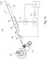
- the sheet-processing machine arrangement chosen as an example initially has, as seen in the transport direction T of the sheets, a sheet feeder 01 in which a first stack 02 of sheets is ready for processing.
- the sheets are preferably rectangular substrates made of paper, cardboard or paperboard. Paper, cardboard and paperboard differ in their respective grammage, i.e. the weight in grams for one square meter of these sheets.
- Paper has a basis weight of between 30 g/m 2 and 150 g/m 2
- cardboard has a basis weight of between 150 g/m 2 and 600 g/m 2
- paperboard has a basis weight of more than 600 g/m 2
- the sheets can also each be a substrate made of a plastic and/or be designed as a thin panel.
- the sheet feeder 01 can also be designed as a magazine feeder having a plurality of first stacks 02.
- a suction head 03 grasps each of the stacked sheets from above and guides these sheets are fed, for example by means of a first oscillating gripper 04 and optionally a transfer drum 34 interacting with the first oscillating gripper 04, in a sequence of sheets separated from one another, for example to a first coating device 05, this first coating device 05 being designed, for example, as a primer application device.
- the first coating device 05 has a transport cylinder 06, designed, for example, as a printing cylinder, and, for example, a printing unit cylinder 07 interacting with this transport cylinder 06 with an application roller 08, preferably in the form of an anilox roller, which is positioned or at least can be positioned on this printing unit cylinder 07, with at least one doctor blade 09 or a chamber doctor blade system 09 extending in the axial direction of the application roller 08 for the optimal metering of a coating material to be applied to the surface of the sheets.
- the transport cylinder 06 transports the sheets held on its outer surface along a curved, in particular circular arc-shaped transport path.
- the first coating device 05 applies the coating material, e.g.
- the sheets are then transferred from the transport cylinder 06 of the first coating device 05, e.g. by means of a first gripper system 11, in particular a first chain conveyor, and e.g. at least one first conveyor belt 12, to a non-impact printing device 13, wherein the first gripper system 11 and the first conveyor belt 12 interact when transferring the sheets to the non-impact printing device 13, in such a way that the first gripper system 11 delivers the sheets to the first conveyor belt 12, which has a linear transport path, wherein the sheets are transferred to the non-impact printing device 13 from the first conveyor belt 12.
- a first gripper system 11 in particular a first chain conveyor, and e.g. at least one first conveyor belt 12
- the first gripper system 11 and the first conveyor belt 12 interact when transferring the sheets to the non-impact printing device 13, in such a way that the first gripper system 11 delivers the sheets to the first conveyor belt 12, which has a linear transport path, wherein the sheets are transferred to the non-impact printing device 13 from the first conveyor belt 12.
- the first conveyor belt 12 is preferably designed as a circulating endless belt.
- a first dryer 14 is provided in the area of the first gripper system 11 for drying the sheets coated in the first coating device 05, wherein this dryer 14 is designed, for example, as a hot air dryer and/or as a dryer that dries by IR radiation or by UV radiation.
- the non-impact printing device 13 generally has at least four inkjet printing devices that can be controlled independently of one another, with each of these inkjet printing devices applying a different printing ink to the side of the sheet that was previously coated, for example, in the first coating device 05, in order to create a preferably multi-colored print image.
- the non-impact printing device 13 preferably has a second conveyor belt 16 so that the sheets are printed on by the inkjet printing devices while they are lying on this second conveyor belt 16.
- the second conveyor belt 16 is preferably designed as a rotating endless belt. However, several conveyor belts 16 can also be provided, for example on two conveyor belts 16 arranged parallel to one another in the transport direction T of the sheets.
- a second dryer 17 that dries the printed sheets is arranged downstream of the non-impact printing device 13, with this second dryer 17 also being able to e.g. B. as a hot air dryer and/or as a dryer drying by IR radiation or by UV radiation.
- the second dryer 17 has a transport device 18 which transports the sheets lying down in a translational manner, ie along a linear transport path. This transport device 18 is in the Fig. 1
- the third conveyor belt 18 is also preferably designed as a continuous endless belt.
- the conveyor device 18 of the second dryer 17 in this example transfers the dried sheets to a suction belt table 19, from which the sheets are transferred to a second coating device 22, for example by means of a second oscillating gripper 21 and, if appropriate, a transfer drum 33 that interacts with the second oscillating gripper 21.
- the second coating device 22 is designed, for example, as a varnishing device, with this second coating device 22 applying a coating material, for example a varnish, in particular to a print image previously created in the non-impact printing device 13.
- the second coating device 22 has, as a conveyor device for The sheet to be transported has a transport cylinder 23, which is designed, for example, as a printing cylinder, with this transport cylinder 23 interacting, for example, with a printing unit cylinder 24 with an application roller 26, preferably in the form of an anilox roller, which is positioned or at least positionable on this printing unit cylinder 24, with at least one doctor blade 27 or a chamber doctor blade system 27 extending in the axial direction of the application roller 26.
- a transport cylinder 23 which is designed, for example, as a printing cylinder, with this transport cylinder 23 interacting, for example, with a printing unit cylinder 24 with an application roller 26, preferably in the form of an anilox roller, which is positioned or at least positionable on this printing unit cylinder 24, with at least one doctor blade 27 or a chamber doctor blade system 27 extending in the axial direction of the application roller 26.
- the sheets are then transported by the transport cylinder 23 of the second coating device 22, for example by means of a second gripper system 28, in particular a second chain conveyor, to a delivery 29, wherein the sheets processed in this machine arrangement described by way of example are deposited by the second gripper system 28 in the delivery, preferably in a second stack 32.
- a third dryer 31 is provided in the area of the second gripper system 28, which dries the sheets coated in the second coating device 22, wherein this third dryer 31 is designed, for example, as a hot air dryer and/or as a dryer that dries by IR radiation or by UV radiation.
- the delivery 29 can also be designed as a multi-stack delivery having a plurality of second stacks 32.
- the Fig. 1 The machine arrangement shown as an example is designed as a digital printing machine for use in an industrial printing process, in particular for the production of printed products in mass production.
- Fig. 2 shows a side view of the suction belt table 19, as it is used in a machine arrangement according to the Fig. 1
- the transport direction T of the sheets is in the Fig. 2 from right to left. 19 individual sheets are fed sequentially to the suction belt table from a Fig. 2 only partially shown transport device 18 at a transport speed of several thousand sheets per hour, e.g. of about 10,000 sheets per hour.
- transport direction T adjacent, ie in the sequence immediately following one another, individual sheets are spaced apart from each other by a gap. This gap is significantly smaller than a length of the sheets extending in the transport direction T of the sheets and is only a few millimeters, e.g. about 20 mm.
- the transport device 18 arranged upstream of the suction belt table 19 in the transport direction T of the sheets belongs to a dryer 17, this dryer 17 being arranged in accordance with the Fig. 1
- the machine arrangement shown by way of example is a second dryer 17, whereby the sheets are transported by this transport device 18 lying, in particular lying on a conveyor belt, in a translatory manner, ie along a linear transport path.
- the suction belt table 19 initially takes over each individual sheet in a conveying plane defined by the transport device 18 arranged upstream of this suction belt table 19 and theoretically extended in the transport direction T of the sheets, whereby this conveying plane is preferably aligned horizontally.
- the conveying plane E19 ( Fig.
- each sheet strikes with its leading edge in the transport direction T against front marks 36 of the oscillating gripper 21 arranged downstream of the suction belt table 19, this oscillating gripper 21 being in the Fig. 1
- the machine arrangement shown as an example is a second oscillating gripper 21. From this oscillating gripper 21, each sheet is transferred individually to a transfer drum 33 that interacts with this oscillating gripper 21. The sheets are completely braked at the front lays and aligned in register.
- the suction belt table 19 has a sub-shingling device for sheets to be transported.
- the sub-shingling device has a preferably over the entire width of the sheets, ie transversely to the transport direction T of the sheets, the so-called blow box 37, wherein in the blow box 37, on the side thereof facing the conveying plane E19 of the suction belt table 19, a plurality of blow nozzles are arranged one behind the other in the transport direction T of the sheets.
- at least two rows of a plurality of blow nozzles arranged next to one another are arranged one behind the other in the transport direction T of the sheets and in each case transversely to the transport direction T of the sheets.
- a respective blowing direction of the blow nozzles is directed essentially parallel to the conveying plane E19 of the suction belt table 19, against the transport direction T of the sheets.
- the respective blowing direction of the blow nozzles is determined, for example, by at least one guide surface which channels the flow of the blowing air and is arranged and/or molded onto the respective blow nozzle.
- the respective guide surface is, for example, on the side of the blow box 37 facing the conveying plane E19 of the suction belt table 19. B. designed as a ramp protruding from this blow box 37.
- Blowing air flowing out of the respective blow nozzles is preferably controlled by adjustable pneumatic valves, e.g.
- valves are controlled, e.g., by a preferably digital control unit 71 that processes a program.
- the valves are switched, e.g., by the control unit 71 in particular in a cycle, wherein a cycle duration and/or a cycle frequency is preferably set depending on the advance of the sheets fed to the suction belt table 19.
- Valves controlled in a cycle by a preferably digital control unit 71 are also referred to as cycle valves.
- a bulkhead plate 38 is arranged in a region between the conveying plane E19 of the suction belt table 19 and the side of the blow box 37 facing this conveying plane E19 in front of the first blow nozzle or the first row of blow nozzles, wherein the bulkhead plate 38 protects the front edge of a subsequent sheet, ie a sheet which directly follows a sheet lifted by the blowing air from at least one of the blow nozzles of the blow box 37, against the 37 arranged blow nozzles.
- the arch raised by at least one of the blow nozzles or blow nozzle rows of the blow box 37 from the conveying plane E19 of the suction belt table 19 channels the blowing air flowing out of the at least one blowing nozzle of the blow box 37 and guides this blowing air over the surface of the partition plate 38 facing the blow box 37.
- the partition plate 38 preferably has a concave curvature at its end located in the blowing direction, this curvature giving the blowing air an outflow direction facing away from the conveying plane E19 of the suction belt table 19.
- the leading edge of a sheet which directly follows a sheet lifted by the blowing air from at least one of the blowing nozzles remains unaffected until the lifted sheet, through its own movement progress or advance directed in the transport direction T, exposes with its rear end the blowing nozzle or row of blowing nozzles which this sheet first reaches in its transport direction T.
- the blowing air of the blowing nozzle or row of blowing nozzles in question is switched off by means of the respective associated valve depending on the progress of movement or feed of the sheet that is currently lifted by the conveying plane E19 of the suction belt table 19 and directly precedes a sheet located between the bulkhead plate 38 and the conveying plane E19 of the suction belt table 19.
- a sheet lifted by the blowing nozzles or blowing nozzle rows is lifted due to the suction effect (Venturi effect) caused by the respective blowing air above the conveying plane E19 of the suction belt table 19 to a certain floating height, e.g. measured by a distance from the side of the blow box 37 facing the conveying plane E19 of the suction belt table 19, whereby this floating height depends on the intensity of the respective blowing air and/or on the mass of the sheet in question and/or on the transport speed of the sheet in question.
- a certain floating height e.g. measured by a distance from the side of the blow box 37 facing the conveying plane E19 of the suction belt table 19, whereby this floating height depends on the intensity of the respective blowing air and/or on the mass of the sheet in question and/or on the transport speed of the sheet in question.
- a support plate supporting the raised sheet is preferably provided in the area between the conveying plane E19 of the suction belt table 19 and the side of the blow box 37 facing this conveying plane E19, wherein the support plate, e.g. arranged at an acute angle to the side of the blow box 37 facing the conveying plane E19 of the suction belt table 19, is designed e.g. in the form of an air-permeable grid.
- the sheet lifted by the suction of the blowing air and placed against the support plate is guided there in a smooth movement, i.e. without fluttering, in its transport direction T along this support plate.
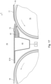
- openings 39 In the conveying plane E19 of the suction belt table 19, preferably several openings 39 ( Fig. 3 ) through which air flows under the currently raised sheet to equalize the pressure. These openings 39 are, for example, circular with a diameter in the range of a few millimeters.
- suction chambers 41 are arranged below the conveying plane E19 of the suction belt table 19, the respective flow effects of which can be controlled. These suction chambers 41 are preferably arranged one behind the other in the transport direction T of the sheets and their respective pressure can be switched, for example, individually and independently of one another by means of a suction device controlled by the control unit 71.
- Fig. 3 shows in a top view the Fig. 2
- the transport direction T of the sheets is as shown in the Fig. 2 from right to left.
- individual sheets are fed sequentially to the suction belt table 19 by a transport device that transports the sheets in a translatory manner, in particular by a transport device belonging to a dryer 17.
- the sheets are each located on at least one conveyor belt 18, preferably on several, e.g. on two conveyor belts 18 arranged parallel to one another in the transport direction T of the sheets.
- These conveyor belts 18 are each designed, for example, as endlessly rotating flat belts or flat belts.
- a guide device 42 extending transversely to the transport direction T of the sheets is arranged, preferably with several lifting nozzles 43 arranged in at least one row.
- at least one transfer belt 44 which is designed, for example, as a rotating flat belt arranged in the middle area of the conveying plane E19 of the suction belt table 19 and also preferably as a suction belt, the suction belt having a perforation at least in sections.
- two consecutive bends 46; 47 are shown, the first bend 46 being arranged in the effective area of the transfer belt 44 and the second bend 47 being arranged at a short distance of less than one sheet length in the transport direction T of the sheets after the transfer belt 44.
- the conveying plane E19 of the suction belt table 19 for example symmetrically to its center line M, spanning the distance between the bends 46; 47, preferably two jump belts 48 arranged parallel to one another in the transport direction T of the sheets, for example in the form of endless belts that each run around and are preferably each designed as a suction belt.
- the skid belts 48 are pivotally mounted at their rear end in the transport direction T of the sheets, which is thus reached first by a sheet fed in, in particular, by the transfer belt 44, so that these skid belts 48 extend obliquely upwards from the previous conveying plane E19 of the suction belt table at an acute angle opening in the transport direction T of the sheets. 19 can be swung out and in their extended operating state form a raised ramp for the sheets to be transported.
- the skid belts 48 are shown in their normal operating state, i.e. not swung out and preferably flush with the rest of the conveyor plane E19 of the suction belt table 19.
- nozzles 49 are arranged at least in the respective longitudinal edge areas of the area of the conveyor plane E19 of the suction belt table 19 spanned by the skid belts 48.
- This arrangement of the venturi nozzles begins in the transport direction T of the sheets at a distance of e.g. less than 200 mm, preferably less than 100 mm behind the at least one lifting nozzle 43.
- a blower 51 extending transversely to the transport direction T of the sheets is arranged at a distance A51 ( Fig. 2 and 3 ), this catch blower 51 having a plurality of blow nozzles which are arranged in a row extending over the entire width B19 of the conveying plane E19 of the suction belt table 19.
- a switching area 52 with several suction holes 53 begins, extending in the transport direction T of the sheets.
- the suction holes 53 in the switching area 52 form and open a fluidic connection to at least one of the preferably several suction chambers 41 each arranged below the conveying plane E19 of the suction belt table 19, wherein these suction chambers 41 are switched or at least switchable by the control unit 71, in particular individually and independently of one another in their respective pressure, so that in this switching area 52 by means of the suction holes 53 and by the respective setting of the pressure in the relevant suction chamber 41 in the conveying plane E19 of the suction belt table 19, a negative pressure can be set or at least adjusted.
- the suction holes 53 arranged in the switching area 52 are, for example, symmetrical to the center line M of the conveying plane E19 of the Suction belt table 19 are arranged in several rows, e.g.
- At least one feed belt 54 designed in particular as a suction belt, adjoins the switching area 52, e.g. in an overlapping manner with the switching area 52, the suction belt having a perforation at least in sections, the at least one feed belt 54 extending in the transport direction T of the sheets preferably to below the blow box 37 of the shingling device.
- the at least one feed belt 54 is preferably designed as a rotating endless belt.
- several, e.g. two, feed belts 54 are provided, e.g. symmetrical to the center line M of the conveying plane E19 of the suction belt table 19.
- brake belts 56 which are arranged symmetrically to their center line M and are preferably designed as a continuous endless belt, which have the function of reducing the respective transport speed of the sheets fed in before they are transferred to a transport device immediately downstream of the suction belt table 19, for example to an oscillating gripper 21.
- the sheets which are preferably reduced in their respective transport speed, are then gripped by a rotating or at least rotatable suction roller 57, which is subjected to negative pressure by a suction device, during their further movement in the transport direction T, wherein this suction roller 57 is arranged transversely to the transport direction T of the Sheets preferably extend at least over the entire width of the sheets or over the entire width B19 of the suction belt table 19. Then each of the sheets, one after the other and individually held by the suction roller 57, reaches with its front edge in the transport direction T, i.e. its front edge, e.g. to the front lays 36 of the oscillating gripper 21 arranged immediately downstream of the suction belt table 19.
- the sheets which were previously transported individually, one behind the other, with a gap between them, are transferred into an shingled stream before these sheets are transferred to a transport device arranged immediately downstream of the suction belt table 19, e.g. to an oscillating gripper 21, in order to then be rotated in a machine arrangement having this suction belt table 19, e.g. designed as a digital printing machine, to a coating device 22, e.g. B. to a coating device 22 designed as a painting device and to be transported through this.
- a transport device arranged immediately downstream of the suction belt table 19, e.g. to an oscillating gripper 21, in order to then be rotated in a machine arrangement having this suction belt table 19, e.g. designed as a digital printing machine, to a coating device 22, e.g. B. to a coating device 22 designed as a painting device and to be transported through this.
- a malfunction can occur for various reasons in a processing station downstream of the suction belt table 19, e.g. designed as a coating device 22.
- a serious malfunction in such a processing station results in the transfer of sheets to the transport device downstream of the suction belt table 19 having to be abruptly interrupted.
- This operating case forms a stopper.
- sheets in transport in the machine arrangement must be collected and stacked very quickly and effectively.
- a suction belt table 19 with a catching device 58 is proposed, with which catching device 58 in a sequence successive individual sheets in front of their transfer to a transport device arranged downstream of the suction belt table 19, they are caught and stacked on the suction belt table 19.
- this suction belt table 19, which preferably has a shingling device, is arranged in the transport direction T of the sheets after a dryer 17 arranged downstream of a non-impact printing device 13.
- the suction belt table 19 is arranged in a machine arrangement at a point at which the sheets are transferred from a linear transport path arranged immediately upstream of this suction belt table 19 to a curved, in particular circular-arc-shaped, transport path arranged immediately downstream of this suction belt table 19.
- the proposed catching device 58 has a slider crank mechanism, the coupling of which has at least one stop surface 66 for the sheets to be caught. Details of the catching device 58 and its functionality are explained below using the Fig. 4 to 6 described.
- Fig. 4 shows an example of a side view of the catching device 58.
- This catching device 58 is arranged, as long as it is inactive, e.g. not actuated by the control unit 71, below the conveying plane E19 of the suction belt table 19, preferably approximately one sheet length extending in the transport direction T of the sheets from a line drawn by the catching blower 51 perpendicular to the conveying plane E19 of the suction belt table 19 corresponding to the distance A51 at the end of the switching area 52 of this suction belt table 19 having suction holes 53.
- the catching device 58 has a drive 59, which is preferably designed as a double-acting pneumatic cylinder 81, the cylinder piston 82 of which can be pressurized with compressed air on both sides ( Fig. 8 ).
- a bidirectional linearly movable piston rod 61 of the pneumatic cylinder 81 is connected to a crank 62 designed as an angle lever by forming a pivot point G61, the crank 62 being rotatably mounted in a pivot point D62 fixed in the suction belt table 19.
- the Crank 62 designed as an angle lever, has a short lever and a lever that is longer than this short lever, the short lever connecting the articulation point G61, at which the piston rod 61 of the pneumatic cylinder 81 is connected to the crank 62, to the pivot point D62 of the crank 62.
- the crank 62 is in turn connected to a coupling 63, forming an articulation point G62.
- the longer lever of the crank 62 extends between its pivot point D62 and the articulation point G62, at which the crank 62 is connected to the coupling 63.
- the coupling 63 and the crank 62 driving the coupling 63 form a slider-crank mechanism in their interaction, an end point E2 of the coupling 63 facing away from the drive 59 of the catching device 58 being bidirectionally linearly movable along a path 64 arranged parallel to the conveying plane E19 of the suction belt table 19.
- the end point E2 of the coupling 63 facing away from the drive 59 of the catching device 58 and the pivot point D62 of the crank 62 therefore lie on a straight line G64 connecting them, this straight line G64 running parallel to the conveying plane E19 of the suction belt table 19.
- the coupling 63 has at least one stop surface 66 for sheets to be caught in an area between its end point E1 facing the drive 59 of the catching device 58 and the articulation point G62 at which the crank 62 is connected to the coupling 63.
- the stop surface 66 in question is therefore preferably a component of the coupling 63.
- the stop surface 66 in question is preferably made of a plastic, e.g. from a polyamide (abbreviation PA) or from a thermoplastic such as e.g. polyoxymethylene (abbreviation POM).
- the slider crank mechanism has a centric slider crank, which means that the three Fig. 4 shown sections G62-D62, G62-E2 and G62-E1 are each of the same length and the end points E1; E2 of the coupling 63 together with the joint point G62 arranged between them all lie on a straight line G63 connecting the end points E1; E2 of the coupling 63.
- the short lever and the longer lever of the crank 62 are designed in their length ratio to one another in such a way that they translate a movement triggered by the drive 59 of the arresting device 58 and acting on the coupling 63 into a faster speed.
- FIG. 2 and 5 show the catching device 58 in its inactive, ie unactuated starting position or parking position, in which the at least one stop surface 66 formed on the coupling 63 is arranged below the conveying plane E19 of the suction belt table 19.
- the sheets can pass the suction belt table 19 in its conveying plane E19 unhindered, which in the Fig. 5 is indicated by two consecutive directional arrows.
- the piston rod 61 of the pneumatic cylinder 81 forming the drive 59 of the safety device 58 is extended by a corresponding application of compressed air to this pneumatic cylinder 81 and the end point E2 of the coupling 63 facing away from the drive 59 of the safety device 58 takes up its position on the track 64 furthest from the drive 59 of the safety device 58.
- the Fig. 6 and 7 show the catching device 58 in its catching position.
- the at least one stop surface 66 preferably formed on the coupling 63, penetrates through a corresponding, e.g. slot-shaped opening 67 ( Fig. 3 ) the conveying plane E19 of the suction belt table 19 and, by means of a pivoting movement, positions itself from a position previously inclined at a preferably acute angle to the conveying plane E19 of the suction belt table 19, preferably perpendicular to this conveying plane E19 ( Fig.
- Fig. 7 shows an excerpt from the Fig. 2 with skid belts 48, which are shown in their operating state protruding obliquely upwards from the previous conveyor level E19 of the suction belt table 19 at an acute angle opening in the transport direction T of the sheets, as well as with a catch blower 51 activated, for example, by the control unit 71, the activation of which in the Fig. 7 is indicated by a blowing direction arrow directed towards the conveying plane E19 of the suction belt table 19.
- the catching device 58 is switched to its catching position by the drive 59 of the catching device 58 being automatically, in particular program-controlled, actuated by a control unit 71, usually by the further control unit 71 that preferably controls all functions of the suction belt table 19.
- This control unit 71 also controls, for example, the valves of the blow box 37 ( Fig. 2 ).
- the transport speed of the sheets can be reduced, for example, by Catching device 58 in the transport direction T of the sheets, transport devices arranged upstream of the catch 58 reduce their respective transport speed. Even if the transport speed of a transport device arranged upstream of the catch 58 in the transport direction T of the sheets is not immediately reduced when the catch 58 is actuated, e.g.
- the negative pressure set in the relevant suction chamber 41 by means of a suction device 72 controlled by the control unit 71 is switched off in any case, this suction chamber 41 being fluidically connected to the relevant switching area 52 by means of the suction holes 53 formed in the conveying plane E19 of the suction belt table 19 and at least partially overlapping with a floor plan of the stack of sheets to be caught.
- the at least one stop surface 66 of the catch 58 is then shot into a sheet gap between the rear edge of a previous sheet and a front edge of a first subsequent sheet to be caught.
- control unit 71 actuates at least one pneumatic switching valve 86, preferably two pneumatic switching valves 86; 87 simultaneously, so that the piston rod 61 of the pneumatic cylinder 81 forming the drive 59 of the catching device 58 is retracted.
- this pneumatic cylinder 81 has a bottom chamber 68 and a bearing chamber 69 separated from the bottom chamber 68 by a cylinder piston 82 firmly connected to the piston rod 61, wherein a first pneumatic switching valve 86 is connected to the bottom chamber 68 and a second pneumatic switching valve 87 is connected to the bearing chamber 69.
- These two switching valves 86; 87 are each controlled by the control unit 71 of the catching device 58.
- the bottom chamber 68 can have barometric pressure.
- the bottom chamber 68 can have a differential pressure greater than the barometric pressure and less than the pressure in the bearing chamber 69.
- the piston rod 61 of the pneumatic cylinder 81 forming the drive 59 of the catching device 58 is retracted by pressurizing the bearing chamber 69, e.g. with 7 bar.
- the cylinder piston 82 of the pneumatic cylinder works against compressed air pre-pressurized in the base chamber 68, e.g. with 2 bar, which can escape in a throttled manner via the open pneumatic switching valve 86 of the base chamber 68 and, if necessary, via a subsequent throttle valve 91.
- the proposed slider-crank mechanism it is possible to bring at least one stop surface 66 of the catching device 58 into the catching position even at a high sheet transport speed of several thousand sheets per hour, e.g. of around 10,000 sheets per hour, through a sheet gap measuring only around 20 mm, for example.
- the reaction time achievable with the proposed slider-crank mechanism thus significantly exceeds the switching times of simple folding and/or sliding mechanisms which are driven, for example, by switching magnets or directly, i.e. gearless, by a pneumatic cylinder 81.
- a further advantage of the solution found is that the proposed slider-crank mechanism is comparatively simple and space-saving.
- Sheets are arranged one behind the other, with at least one of these processing stations having a transport device 18 which transports the sheets lying down along a linear transport path, with this transport device 18 being designed to transport individual sheets which follow one another directly in succession in a sequence, each one spaced apart from one another by a gap, with a suction belt table 19 being arranged downstream of this transport device 18 which transports the sheets lying down along a linear transport path, the suction belt table 19 having a catching device 58 with a catching position assumed as a result of an actuation for individual sheets which follow one another in a sequence, the catching device 58, in its catching position, catching and stacking sheets fed to the suction belt table 19 by the transport device 18 which transports the sheets lying down along a linear transport path and is arranged upstream of the suction belt table 19, on the suction belt table 19 before they are respectively transferred to a transport device arranged downstream of the suction belt table 19.
- a control unit 71 provided for the suction belt table 19 actuates the catching device 58 depending on a fault that has occurred in a processing station downstream of the suction belt table 19 such that the catching device 58 assumes its catching position.
- the transport device 18 arranged upstream of the suction belt table 19, which transports the sheets lying down along a linear transport path, belongs to a dryer 17.
- This dryer 17 is arranged downstream of a processing station designed as a non-impact printing device 13, for example.
- the suction belt table 19 is also preferably arranged upstream of a processing station designed as a coating device 22, in particular a varnishing device.
- the coating device 22 has a transport cylinder 23 as a transport device for sheets to be transported, with this transport cylinder 23 preferably interacting with a printing unit cylinder 24 with an application roller 26 that is or can at least be positioned on this printing unit cylinder 24, with at least one doctor blade 27 or a chamber doctor blade system 27 extending in the axial direction of the application roller 26.
- This machine arrangement is the sheets with a Transport speed preferably of several thousand sheets per hour, in particular of about 10,000 sheets per hour.
- the transport device 18 arranged upstream of the suction belt table 19, which transports the sheets lying down along a linear transport path, is designed to transport the individual sheets which follow one another in a sequence, each with a sheet gap preferably measuring about 20 mm.
- a suction belt table 19 for sheet-shaped substrates to be transported lying individually the suction belt table 19 being arranged between a transport device arranged upstream in the transport direction T of the substrates and a correspondingly downstream transport device, the suction belt table 19 having a catching device 58 with a catching position assumed as a result of its actuation for individual substrates which follow one another in a sequence, the catching device 58 in its catching position catching substrates fed to the suction belt table 19 from the upstream transport device on the suction belt table 19 before they are respectively transferred to the transport device arranged downstream of the suction belt table 19, i.e. preventing them from moving forward in the transport direction T and stacking them.
- the transport device upstream of the suction belt table 19 has a translatory transport path for the sheet-shaped substrates to be transported individually lying down and/or the transport device downstream of the suction belt table 19 has a rotary transport path or a translatory transport path for the sheet-shaped substrates to be transported.
- a control unit 71 in particular a digital one, is provided, wherein this control unit 71 actuates the catching device 58 depending on a disturbance that has occurred along the transport path belonging to the transport device downstream of the suction belt table 19 in such a way that the catching device 58 assumes its catching position.
- the catching device 58 has at least one pivotable stop surface 66 for substrates to be caught, wherein the stop surface 66 in question can be pivoted in the direction of the Control unit 71, in the unactuated state of the catching device 58, it is arranged below a conveying plane E19 of the suction belt table 19, and in the state of the catching device 58 actuated by the control unit 71, it is pivoted through an opening 67 in the conveying plane E19 of the suction belt table 19 and positioned perpendicular to this conveying plane E19, so that substrates transported on the suction belt table 19 strike against the at least one raised stop surface 66 protruding from the conveying plane E19 of the suction belt table 19.
- the catching device 58 has a slider-crank mechanism, the slider-crank mechanism having a coupling 63 and a crank 62 interacting with the coupling 63, the crank 62 being driven by a drive 59.
- the crank 62 is rotatably mounted in a pivot point D62 arranged in a fixed position in the suction belt table 19, the crank 62 being designed as an angle lever and having a short lever and a lever that is longer than this short lever, the short lever connecting a pivot point G61, at which the drive 59 engages the crank 62, to the pivot point D62 of the crank 62, the longer lever of the crank 62 extending between its pivot point D62 and a pivot point G62, at which the crank 62 is connected to the coupling 63.
- the length ratio of the short lever and the longer lever of the crank 62 to one another is such that they translate a movement acting on the coupling 63 from the drive 59 of the catching device 58 into a faster speed.
- the transmission ratio i into a faster speed is preferably at least 1:5.
- An end point E2 of the coupling 63 facing away from the drive 59 of the catching device 58 is bidirectionally linearly movable along a path 64 arranged parallel to the conveying plane E19 of the suction belt table 19, wherein the end point E2 of the coupling 63 facing away from the drive 59 of the catching device 58 and the pivot point D62 of the crank 62 are arranged on a straight line G64 connecting these two points, wherein this straight line G64 runs parallel to the conveying plane E19 of the suction belt table 19.
- the at least one stop surface 66 for substrates to be caught is in a region between an end point E1 of the coupling 63 facing the drive 59 of the catching device 58 and the articulation point G62 at which the crank 62 is connected to the coupling 63. is connected.
- the slider crank mechanism preferably has a central slider crank, in which the three sections G62-D62; G62-E2; G62-E1 are each of the same length and the end points E1; E2 of the coupling 63 together with the articulation point G62 arranged between them are all arranged on a straight line G63 connecting the end points E1; E2 of the coupling 63.
- the drive 59 of the catching device 58 is advantageously designed as a double-acting pneumatic cylinder 81, this pneumatic cylinder 81 having a bottom chamber 68 and a bearing chamber 69 separated from the bottom chamber 68 by a cylinder piston 82 firmly connected to its piston rod 61.
- the bearing chamber 69 is arranged at that end of the pneumatic cylinder 81 which faces the articulation point G61 at which the drive 59 engages the crank 62.
- the bottom chamber 68 is arranged at the end of the pneumatic cylinder 81 that faces away from the articulation point G61 at which the drive 59 engages the crank 62.
- a first pneumatic switching valve 86 is connected to the bottom chamber 68 and a second pneumatic switching valve 87 is connected to the bearing chamber 69, whereby these two switching valves 86; 87 are each controlled by the control unit 71 of the catching device 58.
- the bottom chamber 68 either has barometric pressure or the bottom chamber 68 has a differential pressure greater than the barometric pressure and less than the pressure in the bearing chamber 69.
- the piston rod 61 of the pneumatic cylinder 81 is retracted by applying pressure to the bearing chamber 69, e.g. with 7 bar.
- the cylinder piston 82 of the pneumatic cylinder 81 works against compressed air pre-pressurized in the bottom chamber 68, for example with 2 bar, wherein this compressed air is provided from a compressed air source 93 connected to the bottom chamber 68.
- a suction belt table 19 for the horizontal transport of individual sheet-shaped substrates in a conveyor plane E19 wherein the suction belt table 19 has a catching device 58 and at least one skid belt 48, wherein the catching device 58 and the at least one skid belt 48 are each supported by a Control unit 71 controlled, are designed to assume one of two different operating states, wherein with respect to the catching device 58 and the at least one skid belt 48, the first operating state is an inactive operating state and the second operating state is an activated operating state, wherein the catching device 58 in its activated state has at least one stop surface 66 set up perpendicular to the conveying plane E19 of the suction belt table 19 for substrates to be caught, wherein the at least one skid belt 48 is arranged in the transport direction T of the substrates by at least one substrate length extending in the transport direction T of the substrates in front of the at least one stop surface 66 set up perpendicular to the conveying plane E19 of the suction belt table
- the suction belt table 19 is arranged between a transport device arranged upstream in the transport direction T of the substrates and a correspondingly downstream transport device, wherein the transport device arranged upstream of the suction belt table 19 has a translatory transport path for the sheet-shaped substrates to be transported individually and/or the transport device arranged downstream of the suction belt table 19 has a rotary transport path or a translatory transport path for the sheet-shaped substrates to be transported.
- a catching blower 51 with several blow nozzles arranged in a row extending transversely to the transport direction T of the substrates is arranged, wherein the catching blower 51 in its activated state blows air from its blow nozzles e.g. vertically in the direction of the conveying plane E19 of the suction belt table 19 blows.
- the control unit 71 actuates the catching device 58 as a function of a fault that has occurred along the transport path belonging to the transport device downstream of the suction belt table 19 in such a way that the catching device 58 sets up its at least one stop surface 66 for substrates to be caught perpendicular to the conveying plane E19 of the suction belt table 19 and/or this control unit 71 actuates the at least one skid belt 48 as a function of the fault that has occurred along the transport path belonging to the transport device downstream of the suction belt table 19 in such a way that the at least one skid belt 48 is pivoted out of the conveying plane E19 of the suction belt table 19 at an acute angle obliquely upwards and/or this control unit 71 actuates the catching blower 51 as a function of the fault that has occurred along the transport path belonging to the transport device downstream of the suction belt table 19 in such a way that the catching blower 51 blows air from its Blow nozzles in the direction of the conveying plane E19 of
- the suction belt table 19 is preferably designed such that in the transport direction T of the substrates, after the catching device 58, above the conveying plane E19 of the suction belt table 19, a blow box 37 of an under-shingling device belonging to the suction belt table 19 is arranged.
- a guide device 42 with several lifting nozzles 43 extending transversely to the transport direction T of the substrates is arranged.
- At least one suction chamber 41 is arranged, the respective pressure of the suction chamber 41 being set or at least adjustable by the control unit 71, the control unit 71 being able to control the A negative pressure is set or at least adjustable through suction bores 53 formed in the conveying plane E19 of the suction belt table 19 to the relevant suction chamber 41 in the conveying plane E19 of the suction belt table 19.
- the negative pressure set in the conveying plane E19 of the suction belt table 19 by means of the suction chamber 41 is switched off in the event of a fault occurring along the transport route belonging to the transport device downstream of the suction belt table 19.
- the control unit 71 is preferably designed such that it reduces a transport speed of the substrates at least in the transport device upstream of the catching device 58 in the transport direction T of the substrates.
- two jump belts 48 arranged parallel to one another in the form of each rotating endless belts are provided in the transport direction T of the sheets, these two jump belts 48 being arranged symmetrically to the center line M of the conveying plane E19 of the suction belt table 19.
- a pneumatic drive 59 controlled by the control unit 71 actuates the catching device 58.
- a stopper when a stopper is in operation, due to the high transport speed of several thousand sheets transported in the conveying plane E19 of the suction belt table 19 per hour, e.g. of around 10,000 sheets per hour, and the relatively small gap of e.g.
- a cylinder piston 82 in a pneumatic cylinder 81 exerts such a large force impulse on the inner Stops of this pneumatic cylinder 81 are such that these stops are worn out in a very short time and are thus destroyed.
- this pneumatic cylinder 81 has sufficient wear resistance and thus as unrestricted an operating life as possible when used as described.
- a pneumatic circuit be provided for the operation of the double-acting pneumatic cylinder 81 of the catching device 58, which pneumatic circuit controls the movement of the cylinder piston 82 in such a way that a positive acceleration is set for the cylinder piston 82 in a first half of its stroke and a negative acceleration is set in a second half of its stroke following the first half.
- This pneumatic cylinder 81 has a base chamber 68 and a bearing chamber 69 separated from the base chamber 68 by the cylinder piston 82, the cylinder piston 82 being firmly connected to the piston rod 61.
- the bearing chamber 69 is arranged at that end of the pneumatic cylinder 81 which faces the articulation point G61 at which the drive 59 engages the crank 62.
- the bottom chamber 68 is arranged at the end of the pneumatic cylinder 81 that faces away from the articulation point G61, at which the drive 59 engages the crank 62.
- the cylinder piston 82 preferably has an end position damping element 83; 84 on both sides.
- the pneumatic circuit described in detail below implements a controlled acceleration phase and a controlled braking phase over the entire stroke of the cylinder piston 82 by changing a dynamic pressure equilibrium in the two chambers 68; 69 of the pneumatic cylinder 81.
- the pneumatic circuit has a first pneumatic switching valve 86 and a second pneumatic switching valve 87, wherein both switching valves 86; 87 are each preferably electrically operated by the control unit 71. Both switching valves 86; 87 are in one of their switching positions each connected to their respective compressed air source 93.
- Fig. 8 shows the operating position of the pneumatic cylinder 81 in which the piston rod 61 of the pneumatic cylinder 81 forming the drive 59 of the catching device 58 is retracted and the catching device 58 is thus activated, which means that the stop surface 66 of the catching device 58 is positioned in the conveying plane E19 of the suction belt table 19.
- At least the switching valve 86 for the bottom chamber 68 is preferably preceded by a pressure reducer 88 in order to build up a defined initial counterpressure in the bottom chamber 68 when the compressed air flows out.
- a pressure reducer 89 can also be preceded by the switching valve 87 for the storage chamber 69.
- a throttle valve 91 is arranged downstream of the switching valve 86 of the base chamber 68 in order to use this throttle valve 91, the cross-section of which is preferably adjustable, to influence the outflow speed of the compressed air from the base chamber 68 and thus the dynamic pressure curve in the pneumatic cylinder 81 and thus the speed of the cylinder piston 82.
- a throttle valve 92 is also arranged in the air outlet from the bearing chamber 69 of the pneumatic cylinder 81 in order to limit the speed of the cylinder piston 82.
- the throttle valve 91 of the base chamber 68 and, if applicable, the throttle valve 92 of the bearing chamber 69 are only used when compressed air flows out of the respective chamber 68; 69 into the atmosphere.
- the bearing chamber 69 of the pneumatic cylinder 81 is preferably depressurized, i.e. there is a pressure in it, e.g. equal to the barometric pressure.
- the bearing chamber 69 of the pneumatic cylinder 81 is subjected to a pressure greater than the barometric pressure via the pressure reducer 89 that may be connected to it, e.g. with a pressure that corresponds to the pressure in the bottom chamber 68, i.e. preferably with a pressure of e.g. 2 bar. If the pressure set in both chambers 68; 69 is the same, the cylinder piston 82 is held in a stable end position.
- the bottom chamber 68 which is pre-tensioned with compressed air, e.g. at 2 bar, an air mass that can be controlled via the pressure is made available, which is required to brake the travel movement of the cylinder piston 82 that occurs when the catching device 58 is activated.
- the catching device 58 is activated by shooting its at least one stop surface 66 into a sheet gap between the trailing edge of a previous sheet and the leading edge of a first subsequent sheet to be caught by the two switching valves 86; 87 being actuated by the control unit 71, in particular simultaneously.
- the storage chamber 69 is supplied with compressed air from its compressed air source 93 at more than 5 bar, in particular with a pressure of e.g. B.
- the braking effect sets in in such a way that the movement of the cylinder piston 82 initially experiences a very large acceleration with resulting speed, before this movement of the cylinder piston 82 is largely braked at the end by the actively clamped air column and only a remaining residual speed of less than, for example, 1 0% of the previously achieved maximum possible speed is braked at the end position damping element 83 of the pneumatic cylinder 81.
- the safety catch 58 is activated, the cylinder piston 82 is accelerated over the first half of its stroke and braked over the second half. In the first half of its stroke, the cylinder piston 82 reaches its maximum possible speed.
- the cylinder piston 82 arrives at its respective end position at zero speed. In real operation, however, this is not achieved. Therefore, the small amount of residual energy still present must be dissipated at the respective end position damping element 83; 84.
- This very rapid movement of the cylinder piston 82 is transmitted by the crank 62 to the preferably centrically positioned
- the coupling 63 arranged in the slide crank position is transmitted with a high gear ratio.
- the pneumatic circuit described and the pressure setting values given as examples make it possible to bring at least one stop surface 66 of the catching device 58 into a catching position even at the high transport speed of the sheets mentioned above through the very narrow sheet gap mentioned above.
- the solution shown advantageously avoids high impact loads and load peaks in the entire kinematic system. This is because the clamped air column, which dampens the drive movement of the cylinder piston 82 at the end, particularly in the base chamber 68, effectively prevents the cylinder base from being destroyed.
- a safe end position of the cylinder piston 82 in its retracted state is achieved without additional mechanical elements and therefore without additional costs.
- the pressure reduction in the storage chamber 69 also saves energy and reduces any leakage.
- Fig. 9 to 12 illustrate once again, by way of example, in a diagram over the time t plotted on the abscissa, the dynamic behavior of some physical variables with reference to the cylinder piston 82 of the pneumatic cylinder 81 during a switching process when the catching device 58 of the respective suction belt table 19 is moved from its starting position to its catching position, in particular actuated by a control signal from the control unit 71.
- Fig. 9 shows a change in position of the cylinder piston 82 between its two end positions in the pneumatic cylinder 81. A travel z and thus the stroke of the cylinder piston 82 is shown here, for example, as 10 mm.
- Fig. 9 shows a change in position of the cylinder piston 82 between its two end positions in the pneumatic cylinder 81. A travel z and thus the stroke of the cylinder piston 82 is shown here, for example, as 10 mm.
- FIG. 10 shows, by way of example, the speed v of the cylinder piston 82 during its movement along the travel z.
- Fig. 11 shows as an example the corresponding acceleration a with which the cylinder piston 82 executes its movement along the travel z.
- Fig. 12 The piston force F exerted by the cylinder piston 82 is then shown as an example.
- a suction belt table 19 is produced for the horizontal transport of individual sheet-shaped substrates in a conveyor plane E19, wherein the suction belt table 19 has a catching device 58 with at least one stop surface 66 for substrates to be caught, which is set up in its catching position in the conveyor plane E19 of the suction belt table 19, wherein this at least one stop surface 66 is set up from an inactive starting position of the catching device 58 by a double-acting pneumatic cylinder 81 by a movement of its cylinder piston 82 into the catching position, wherein this pneumatic cylinder 81 has a bottom chamber 68 and a storage chamber 69 separated from the bottom chamber 68 by the cylinder piston 82, wherein a pneumatic circuit is provided for controlling the movement of the cylinder piston 82, wherein the pneumatic circuit has a first pneumatic switching valve 86 connected to the bottom chamber 68 and a second pneumatic switching valve connected to the storage chamber 69.
- the catching device 58 has a slider crank mechanism driven by the cylinder piston 82 of the pneumatic cylinder 81 as described above. The movement of the cylinder piston 82 is controlled by the control unit 71 such that a positive acceleration is set for the cylinder piston 82 in a first half of its stroke and a negative acceleration in a second half of its stroke following the first half.
- a pressure reducer 88 is connected upstream of at least the first switching valve 86 connected to the base chamber 68. Also connected downstream of at least the first switching valve 86 connected to the base chamber 68 is, for example, a throttle valve 91 whose opening cross-section is preferably adjustable.
- the opening cross-section of the throttle valve 91 is, for example, B. set by the control unit 71 in such a way that the movement of the cylinder piston 82 at the end of the second half of its stroke has a residual speed of less than 10% of the maximum speed previously reached in the first half of its stroke.
- the cylinder piston 82 preferably has an end position damping element 83; 84 on both sides, wherein the end position damping element 83; 84 at the end of the second half of its stroke stroke is braked at the relevant end position damping element 83; 84.
- the control unit 71 switches the first switching valve 86 connected to the bottom chamber 68 into a position that diverts the air mass from the bottom chamber 68 and at the same time the second switching valve 87 connected to the bearing chamber 69, so that the bearing chamber 69 is subjected to compressed air at a pressure of more than 5 bar.
- the suction belt table 19 has in its conveying plane E19 a switching area 52 extending in the transport direction T of the sheets with a plurality of suction bores 53, wherein preferably a plurality of suction chambers 41 are arranged below the conveying plane E19 of the suction belt table 19, the respective flow-related effects of which can be controlled.
- These suction chambers 41 are preferably arranged one behind the other in the transport direction T of the sheets and in particular are switched or at least switchable individually and independently of one another in terms of their respective pressure.
- the suction holes 53 in the switching area 52 form a fluidic connection to at least one of the preferably several suction chambers 41 each arranged below the conveying plane E19 of the suction belt table 19, wherein in this switching area 52 a negative pressure can be set or at least adjusted by the respective setting of the pressure in the respective suction chamber 41 by means of a suction device 72 controlled by the control unit 71 at the suction holes 53 in the conveying plane E19 of the suction belt table 19.
- This negative pressure has the effect that a sheet resting on the at least one feed belt 54 in the conveying plane E19 of the suction belt table 19 is held in a frictional or force-locking manner. This is because the switching area 52 overlaps at least partially with the outline of the sheet to be caught.
- the feed belt 54 in question is designed, for example, as an endlessly rotating Suction belt is designed, wherein a suction belt has a perforation at least in sections, so that the negative pressure set at the suction holes 53 in the conveying plane E19 of the suction belt table 19 can be effective on the sheet lying thereon through the relevant feed belt 54.
- the feed belt 54 is preferably designed as a flat belt or as a flat belt.
- At least one pneumatic timing valve 74 controlled by a control unit 71 is arranged in the supply line 73 pneumatically connecting the suction chamber 41 to the respective suction bores 53, the timing valve 74 in question interrupting the pneumatic connection when the catching device 58 is moved into its catching position.
- the timing valve 74 in question is designed in such a way that, at the same time as the pneumatic connection between the suction chamber 41 in question and the respective suction bores 53 is interrupted, a section of the supply line 73 between the timing valve 74 in question and the respective suction bores 53 is ventilated with barometric pressure or with a pressure that is 3% to 10%, preferably 5%, higher than the barometric pressure.
- the transport speed of the sheets corresponds to a cycle time in which immediately successive sheets reach the position of the at least one stop surface 66 of the catching device 58 protruding from the conveying plane E19 of the suction belt table 19.
- a switching time of the relevant timing valve 74 is shorter than the cycle time of immediately successive sheets and is preferably in a range between 20 ms and 100 ms, in particular 40 ms.
- the switching time of the relevant timing valve 74 is the time starting from the time of its actuation until the time at which the relevant timing valve 74 has stably changed from its first operating position to its second operating position.
- the control unit 71 is preferably designed such that it sets the relevant timing valve 74 into the state that interrupts the pneumatic connection between the relevant suction chamber 41 and the respective suction bores 53 by the duration of a cycle time earlier than the actuation of the catching device 58.
- the advantage of this solution is that when a stopper is in operation, the first sheet caught by the catching device 58 is not pushed together or crumpled. Rather, the arrangement of at least one timing valve 74 controlled by the control unit 71 in the supply line 73 between the relevant suction chamber 41 and the respective suction holes 53 ensures that the process of Catching is independent of an unavoidable after-running of the at least one feed belt 54 after detection of the stopper and/or a sustained suction effect of the respective suction chamber 41.
- a plurality of sheets are fed to the suction belt table 19 from a transport device arranged immediately upstream of the suction belt table 19, wherein these sheets are transported one behind the other along a linear transport path, at least in this transport device and on the suction belt table 19, lying individually, each with a narrow gap between them.
- these sheets are transported by means of a plurality of transport belts arranged one behind the other in the transport direction T of the sheets, starting from the revolving transport belt 18 of the transport device arranged immediately upstream of the suction belt table 19 via at least one transfer belt 44 belonging to the suction belt table 19, which is designed, for example, as a revolving flat belt preferably arranged in the middle region of the conveying plane E19 of the suction belt table 19, wherein in the transport direction T the sheet after the transfer belt 44, for example, has two jump belts 48 arranged parallel to one another.
- B. are arranged in the form of circulating endless belts, followed by at least one feed belt 54, in particular designed as a suction belt, and e.g.
- two braking belts 56 arranged parallel to one another, each designed as a circulating endless belt.
- a transport device in the form of a circulating endless belt - to a transport device following the respective transport belt in the transport direction T of the sheets, in the conveying plane E19 the sheets are guided by a deflection roller 76 rotating in this conveying plane E19 of the respective conveyor belt with a gap that is large in relation to the thickness of the sheets, for example between 1 mm and 5 mm, creates a point of discontinuity 78 in the mechanical support of the sheets to be transported, this point of discontinuity 78 entailing the risk of an operational disruption, particularly at a high transport speed of several thousand sheets per hour, for example around 10,000 sheets per hour.
- the deflection roller 76 arranged at the point of discontinuity 78 has, for example, several nozzle-shaped openings, from each of these openings a compressed air jet emerges, wherein one of the compressed air jets is directed at least in the direction of the at least one lifting nozzle 43.
- Fig. 14 shows an example in a top view of a section of the e.g. in connection with the Fig. 3 described suction belt table 19.
- a sheet-shaped substrate preferably a printed sheet, called sheet 77 for short, is transferred to the suction belt table 19 on a conveyor plane E19 as a result of its translatory movement on a circulating conveyor belt 18 belonging to a dryer 17, for example.
- a rotating deflection roller 76 which moves the conveyor belt 18 in the transport direction T of the sheets 77 and deflects it at the end of the transport device immediately upstream of the suction belt table 19.
- Transferred sheets 77 are e.g. B. by a transfer belt 44 belonging to the suction belt table 19, wherein this transfer belt 44 is designed e.g. as a revolving flat belt arranged in the middle area of the conveyor plane E19 of the suction belt table 19 and/or as a suction belt.
- the transfer belt 44 is followed in the transport direction T of the sheets 77 e.g. by two parallel jump belts 48 e.g. in the form of revolving endless belts.
- Fig. 15 shows schematically and in a highly simplified manner, by way of example, the guide device 42 arranged in a discontinuity point 78 relating to the mechanical support of the sheets 77 to be transported, with at least one lifting nozzle 43, preferably with several lifting nozzles 43, wherein this discontinuity point 78 is arranged, for example, between a circulating conveyor belt 16 belonging to a non-impact printing device 13 and a circulating conveyor belt 18 belonging to a dryer 17.
- a sheet 77 transported in the transport direction T tends to be drawn with its front edge into a gap located at the discontinuity point 78 in the periphery of the deflection roller 76, extending transversely to the transport direction T of the sheets 77, due to the rotation of the deflection roller 76, and thus to cause an operational disruption.
- Such a discontinuity point 78 in the mechanical support of the sheets 77 to be transported consists in a Fig. 1 digital printing machine, which transports sheets 77 lying down, shown as an example, at several positions, e.g. at the respective transition to and after the non-impact printing device 13 and at the transition from the dryer 17 to the suction belt table 19.
- Fig. 16 to 19 explain the functioning of the guide device 42 arranged in such a discontinuity point 78 with reference to a digital printing machine that transports sheets 77 lying down at the transition of the sheets 77 from the non-impact printing device 13 to a dryer 17 arranged immediately downstream of the non-impact printing device 13.
- These explanations also apply mutatis mutandis to all other positions at which a generic guide device 42 is arranged or at least can be arranged in the machine arrangement in question, which is preferably designed as a digital printing machine.
- Fig. 16 shows the initial situation for the function of the guide device 42 arranged in the discontinuity point 78.
- a sheet 77 resting on the circulating conveyor belt 16 belonging to the non-impact printing device 13 reaches with its front edge the discontinuity point 78 at the transition of the sheets 77, e.g. from the conveyor belt 16 of the non-impact printing device 13 to a conveyor belt 18 of a dryer 17 arranged immediately downstream of the non-impact printing device 13.
- the guide device 42 has a tapered profile element 79 extending transversely to the transport direction T of the sheets 77, preferably in the form of a doctor blade, the tip of this profile element 79 preferably being approximately tangential against the Transport direction T of the sheets 77 is arranged directed towards the conveyor belt 16 of the non-impact printing device 13, the tip of this profile element 79 being spaced from the conveyor belt 16 of the non-impact printing device 13 deflected on the rotating deflection roller 76, preferably by a gap, this gap having a larger width in relation to the thickness of the sheets 77 in the range e.g. between 1 mm and 5 mm.
- a Fig. 17 The air jet indicated by a direction arrow is directed or at least can be directed against the conveyor belt 16 of the non-impact printing device 13 deflected at the deflection roller 76.
- the sheet 77 resting on the conveyor belt 16 of the non-impact printing device 13 has rotated due to the rotation of the deflection roller 76 in comparison to the Fig. 16 shown initial situation, the gap formed to the guide device 42 is increasingly approached, with the front edge of the sheet 77 in question continuing to follow the curvature of the deflection roller 76 in a manner that potentially provokes a malfunction.
- the air jet blown out of the at least one lifting nozzle 43 arranged in the profile element 79 when the guide device 42 is activated flows against the conveyor belt 16 of the non-impact printing device 13 deflected at the deflection roller 76.
- This air jet hits the conveyor belt 16 in such a way that the direction of the core jet of this air jet intersects the circular circumferential line of the deflection roller 76 as a secant.
- this air jet is directed at the conveyor belt 16 in such a way that a free upper limit of this air jet facing the front edge of the relevant sheet 77 neither intersects nor exceeds a tangent between the circumferential line of the deflection roller 76 and the relevant lifting nozzle 43 of the guide device 42.
- the air jet blown against the convex surface of the conveyor belt 16 of the non-impact printing device deflected at the deflection roller 76 13 is directed there by the curvature of the deflection roller 76 in the direction of the approaching front edge of the relevant sheet 77.
- This air jet which follows the curvature of the deflection roller 76 due to the Coanda effect and is converted into a wall flow, finally releases the front edge of the relevant sheet 77 from the conveyor belt 16 of the non-impact printing device 13 ( Fig. 18 ) and, as the deflection roller 76 continues to rotate, the leading edge of the respective sheet 77 is increasingly lifted away from the conveyor belt 16 of the non-impact printing device 13 due to the resulting dynamic pressure ( Fig. 19 ), so that the front edge of the sheet 77, which is still mostly resting on the conveyor belt 16 of the non-impact printing device 13, is lifted onto the profile element 79 and thus onto the guide device 42 during its further transport.
- the transport device of the non-impact printing device 13 which is arranged directly upstream of the discontinuity point 78 in the transport direction T of the sheets 77 and is mentioned here as an example, has several, e.g. at least two, conveyor belts 16 arranged parallel to one another in the transport direction T of the sheets 77, it can be provided that at least one blow nozzle which emits compressed air in the direction of the sheet 77 resting on these conveyor belts 16 is arranged between adjacently arranged conveyor belts 16.
- the at least one conveyor belt 16 of the transport device arranged immediately upstream of the discontinuity point 78 in the transport direction T of the sheets 77 has raised longitudinal webs, wherein a groove is formed between each adjacent belt web, wherein the tip of the profile element 79 of the guide device 42 is arranged in a comb-like manner protruding into the grooves of the conveyor belt 16 having belt webs.
- the guide device 42 is preferably deactivated, e.g. by the control unit 71, by switching off the air jet flowing out of the at least one lifting nozzle 43.
- the air jet flowing out of the at least one lifting nozzle 43 is thus preferably active in a clocked manner, with this clock starting with the arrival of the leading edge of the respective sheet 77 on the deflection roller 76 of the conveyor belt 16 deflected by means of this deflection roller 76.
- An air jet flowing out of the at least one lifting nozzle 43 of the guide device 42 is therefore preferably only maintained until the front edge of the respective sheet 77 has passed the gap at the point of discontinuity 78 located in the periphery of the deflection roller 76 and extending transversely to the transport direction T of the sheets 77 and the front edge of the respective sheet 77 has been lifted onto the profile element 79 of the guide device 42.
- a A guide device 42 extending in the transport direction T of the sheets 77 is arranged with a tapered profile element 79, the tip of this profile element 79 being directed against the transport direction T of the sheets 77 towards the conveyor belt 16 of the first conveyor device, at least one lifting nozzle 43 being arranged in the profile element 79, the lifting nozzle 43 in question being designed to open out in the direction of the tip of this profile element 79.
- the tip of the profile element 79 is spaced from the conveyor belt 16 of the first conveyor device, which is deflected on the rotating deflection roller 76, by a gap, this gap having a larger width in relation to the thickness of the sheets 77, in the range of between 1 mm and 5 mm.
- a plurality of lifting nozzles 43 are arranged in the profile element 79 in a row extending transversely to the transport direction T of the sheets 77.
- an air jet flowing out of the mouth of the respective lifting nozzle 43 is directed or at least can be directed against the conveyor belt 16 of the first transport device deflected at the deflection roller 76, this air jet being directed at the conveyor belt 16 in such a way that a core jet of this air jet intersects the circumferential line of the deflection roller 76 as a secant.
- the air jet in question is also particularly aligned in such a way that a free upper limit of this air jet facing a front edge of a sheet 77 transported on the conveyor belt 16 of the first transport device neither intersects nor crosses a tangent between the circumferential line of the deflection roller 76 and the respective lifting nozzle 43 of the guide device 42.
- the guide device 42 is activated by the control unit 71.
- the control unit 71 activates the guide device 42 e.g. B. clocked, whereby this clock is synchronized with the arrival of the front edge of the respective sheet 77 at the deflection roller 76 of the conveyor belt 16 of the first transport device deflected by this deflection roller 76.
- the guide device 42 is therefore preferably designed to maintain the air jet flowing out of the relevant lifting nozzle 43 only until the front edge of the respective sheet 77 reaches the air jet located in the periphery of the deflection roller 76 transverse to the transport direction T of the sheets 77. extending gap at the discontinuity point 78 and the front edge of the respective sheet 77 has been lifted onto the tip of the profile element 79 of the guide device 42 by the air jet flowing out of the respective lifting nozzle 43.
- the deflection roller 76 deflecting the at least one conveyor belt 16 of the first transport device and the guide device 42 together with its profile element 79 are each arranged below the conveying plane E19 of the sheets 77 to be transported and preferably flush with this conveying plane E19 at the top. Since the machine arrangement in its preferred embodiment is designed as a digital printing machine, the processing station having the first transport device is designed either as a non-impact printing device 13 or as a dryer 17 or as a cooling section.
- buckled sheets provided at the exit of the dryer 17 can be picked up by a transfer belt 44 of a transport device that is arranged immediately downstream of the dryer 17 in the transport direction T of the sheets, for example B. to a suction belt table 19 or to a cooling section, can no longer be reliably accepted due to inadequate detection, which in a machine arrangement with several transport devices leads very quickly to a malfunction, especially if such sheets follow one another at a transport speed of several thousand sheets per hour, e.g. of about 10,000 sheets per hour.
- the reason for the inadequate detection of the curved sheets is in particular that the curvature of the The bending resistance forces inherent in the respective sheet cannot be overcome by a height-dependent suction force exerted by a suction belt.
- FIG. 20 shows an enlarged section of the Fig. 3 suction belt table 19 shown in a top view, this detail referring in particular to an arrangement of nozzles 49 in an area between one of the two skid belts 48 arranged parallel to one another in the transport direction T of the sheets and an edge 94 running longitudinally to the transport direction T of the sheets and laterally delimiting the conveying plane E19 of the suction belt table 19.
- the skid belts 48, as well as the at least one transfer belt 44 arranged upstream of them in the transport direction T of the sheets, are preferably in the form of each circulating Endless belts, in particular each designed as a suction belt, wherein the suction belt in question is in a pneumatic operative connection with a suction device 72 and can exert a suction force on a sheet lying on it due to its at least partial perforation.
- the transport direction T of the sheets is in the Fig. 20 indicated by a direction arrow.
- a blowing direction of the nozzles 49 arranged in the above-mentioned area, ie a flow direction of an air stream emerging from these nozzles 49 is directed, for example, in the transport direction T of the sheets.
- the blowing direction of the nozzles 49 arranged in this area is either orthogonal to the edge 94 laterally delimiting the conveying plane E19 of the suction belt table 19 or inclined by 45° in the transport direction T of the arc to the edge 94 laterally delimiting the conveying plane E19 of the suction belt table 19. It can also advantageously be provided that the blowing direction of a first subset of the nozzles 49 is e.g. orthogonal to the edge 94 laterally delimiting the conveying plane E19 of the suction belt table 19 and the blowing direction of a second subset of the nozzles 49 is e.g. inclined by 45° in the transport direction T of the arc to the edge 94 laterally delimiting the conveying plane E19 of the suction belt table 19.
- Fig. 21 shows an excerpt from the Fig. 2 shown side view of the suction belt table 19. It is intended that sheets fed to the suction belt table 19, in particular from a dryer 17, are to be picked up by at least one transfer belt 44 and transported further in the conveyor plane E19 of the suction belt table 19.
- the area of the at least one transfer belt 44 and in the area of the jump belts 48 of the suction belt table 19 arranged downstream of the at least one transfer belt 44 in the transport direction T of the sheets or in the transport direction T of the sheets directly adjacent to a discontinuity point 78 in the mechanical support of the sheets to be transported e.g. between the at least one transfer belt 44 belonging to the suction belt table 19 and a rotating conveyor belt 18 belonging to a dryer 17, several nozzles 49 are provided.
- nozzles 49 are in particular designed as Venturi nozzles and are connected to a compressed air source 93 by means of a pneumatically connecting supply line 96.
- a control valve 97 for setting and/or regulating the pressure of an air stream flowing out of the respective nozzle 49 is arranged in the supply line 96 connecting at least one of the nozzles 49 to the compressed air source 93.
- a timing valve 74 controlled, for example, by the control unit 71 is arranged between the relevant control valve 97 and the relevant nozzle 49 in the supply line 96 connecting at least one of the nozzles 49 to the compressed air source 93.
- Such a timing valve 74 is preferably controlled by the control unit 71 in such a way that at least one of the nozzles 49 is supplied with compressed air at exactly the moment when the front edge of a sheet to be transported is covered by the relevant nozzle 49.
- the supply of compressed air to the relevant nozzle 49 is interrupted again by the control unit 71 in particular when the front edge of the relevant sheet to be transported is covered by a nozzle 49 closest to the sheet in the transport direction T.
- the supply of compressed air to the nozzles 49 arranged in the outline of a sheet to be caught is interrupted by means of the relevant timing valve 74 when the catching device 58 of the suction belt table 19 is switched to its catching position.
- a suction belt table 19 with at least one endlessly rotating transfer belt 44 designed as a suction belt for transferring sheets transported individually in a conveying plane E19 from a conveyor belt 18 of a dryer 17 arranged immediately upstream of the suction belt table 19 in the transport direction T of the sheets, wherein the suction belt table 19 has an arrangement of several nozzles 49 in its conveying plane E19 at least in an area between the at least one transfer belt 44 extending longitudinally to the transport direction T of the sheets and an edge 94 laterally delimiting the conveying plane E19 of the suction belt table 19, wherein these nozzles 49 are each designed as Venturi nozzles, wherein a flow direction of at least a first subset of the nozzles 49 arranged in the said region is directed in the transport direction T of the sheets and/or wherein a flow direction of at least a second subset of the nozzles 49 arranged in the said region is directed orthogonally to the edge 94 laterally delimiting the conveying plane E19 of the suction belt table 19 and/
- At least one bend 46; 47 can be formed downstream of the at least one transfer belt 44, with each of these bends 46; 47 the conveying plane E19 of the suction belt table 19 experiences a downward inclination with an acute angle in the range between 5° and 30° compared to the previous alignment of the conveying plane, wherein the arrangement of the nozzles 49 formed in the area between the at least one transfer belt 44 and the relevant edge 94 laterally delimiting the conveying plane E19 of the suction belt table 19 extends in the transport direction T of the sheets beyond the relevant bend 46; 47.
- the nozzles 49 are each arranged, for example, in several rows extending transversely to the transport direction T of the sheets ( Fig. 3 and 20 ).
- the nozzles 49 are each connected to a compressed air source 93 by means of a pneumatically connecting supply line 96, wherein in at least one of the supply lines 96 connecting at least one of the nozzles 49 to the compressed air source 93, preferably a control valve 97 is arranged for setting and/or regulating the pressure of an air flow flowing out of the respective nozzle 49.
- a Timing valve 74 is arranged in the respective supply line 96 connecting at least one of the nozzles 49 to the compressed air source 93.
- the relevant control valve 97 and/or the relevant timing valve 74 are controlled by a control unit 71.
- the relevant timing valve 74 is activated by the control unit 71 in particular when the leading edge of a sheet to be transported is covered by the relevant nozzle 49.
- the relevant timing valve 74 is deactivated by the control unit 71 in particular when the leading edge of the sheet to be transported is covered by a nozzle 49 closest to the sheet in the transport direction T.
- the suction belt table 19 has a catching device 58 with the features described above for sheets to be caught, the relevant timing valve 74 being deactivated by the control unit 71 when the catching device 58 is switched to its catching position.
- the nozzles 49 are each designed as a Venturi nozzle, they generate a suction force on a sheet to be transported which is many times greater in magnitude than a holding force generated by the suction flow on a suction belt arranged in the conveying plane E19 of the suction belt table 19, which is provided for holding a sheet lying flat on the suction belt in question.
- a width of the area having the arrangement of nozzles 49 extending transversely to the transport direction T of the sheets is designed to be significantly larger than the width of the suction belt in question extending transversely to the transport direction T of the sheets, so that the width of the area having the arrangement of nozzles 49 lying outside the width of the suction belt in question is in a much more favorable ratio to the width of the highly curved front edge of the sheet in question.
- an effective area formed by the arrangement of the nozzles 49 and acting on the highly curved front edge of the relevant sheet is significantly larger than the effective area acting on the highly curved front edge of the relevant sheet by the relevant suction belt.
- control unit 71 is thus designed such that it first supplies the nozzles 49 with compressed air and only then, ie with a time delay, does a suction force exerted on the sheet by at least one transfer belt 44 designed as a suction belt begin to act.
Landscapes
- Engineering & Computer Science (AREA)
- Mechanical Engineering (AREA)
- Health & Medical Sciences (AREA)
- General Health & Medical Sciences (AREA)
- Toxicology (AREA)
- Delivering By Means Of Belts And Rollers (AREA)
Claims (15)
- Ensemble machine avec plusieurs stations de traitement traitant respectivement des substrats sous forme de feuilles, dans lequel ces stations de traitement sont disposées les unes derrière les autres dans la direction de transport (T) des substrats en forme de feuilles, dans lequel au moins une de ces stations de traitement présente un dispositif de transport (18) transportant les substrats sous forme de feuilles en position couchée le long d'un trajet de transport linéaire, dans lequel ce dispositif de transport (18) est réalisé de manière à transporter des substrats sous forme de feuilles individuels adjacents dans leur direction de transport (T) et ainsi se suivant immédiatement dans une séquence respectivement de façon espacée les uns des autres par un intervalle, dans lequel une table à bande aspirante (19) est disposée en aval de ce dispositif de transport (18) transportant les substrats sous forme de feuilles en position couchée le long d'un trajet de transport linéaire, dans lequel une autre station de traitement (22) comprenant un dispositif de transport (21) est disposée en aval de la table à bande aspirante (19), dans lequel la table à bande aspirante (19) présente un dispositif de saisie (58) pour des substrats sous forme de feuilles individuels se suivant de manière adjacente, caractérisé en ce que le dispositif de saisie (58) de la table à bande aspirante (19) présente une position de saisie occupée par suite d'un actionnement pour les substrats sous forme de feuilles individuels se suivant de manière adjacente, dans lequel le dispositif de saisie (58) dans sa position de saisie à partir du dispositif de transport (18), qui transporte les substrats sous forme de feuilles en position couchée le long d'un trajet de transport linéaire et est disposé en amont de la table à bande aspirante (19), capture et empile les substrats sous forme de feuilles amenés à la table à bande aspirante (19) sur la table à bande aspirante (19) avant un transfert respectif au dispositif de transport (21) disposé en aval de la table à bande aspirante (19), dans lequel le dispositif de saisie (58) collecte et empile une pluralité des substrats transportés les uns derrière les autres de manière espacée, dans lequel le dispositif de saisie (58) présente au moins une surface de butée (66) pivotante pour les substrats à saisir, dans lequel la surface de butée (66) concernée dans l'état non actionné du dispositif de saisie (58) est disposée au-dessous d'un plan de transport (E19) de la table à bande aspirante (19) et dans l'état actionné du dispositif de saisie (58) est placée perpendiculairement à ce plan de transport (E19) de manière à pivoter par une ouverture (67) dans le plan de transport (E19) de la table à bande aspirante (19), de sorte que les substrats transportés sur la table à bande aspirante (19) se heurtent contre la au moins une surface de butée (66) placée dans la position de saisie, faisant saillie du plan de transport (E19) de la table à bande aspirante (19), dans lequel la au moins une surface de butée (66) du dispositif de saisie (58) est insérée dans les intervalles entre des substrats sous forme de feuilles individuels se suivant immédiatement.
- Ensemble machine selon la revendication 1, caractérisé en ce qu'une unité de commande (71) est prévue, dans lequel cette unité de commande (71) actionne le dispositif de saisie (58) en fonction d'une défaillance apparue dans la station de traitement (22) disposée en aval de la table à bande aspirante (19), de telle sorte que le dispositif de saisie (58) occupe sa position de saisie.
- Ensemble machine selon la revendication 1 ou 2, caractérisé en ce que le dispositif de saisie (58) de la table à bande aspirante (19) présente un mécanisme bielle-manivelle, dans lequel le mécanisme bielle-manivelle présente une bielle (63) et une manivelle (62) coopérant avec la bielle (63), dans lequel la manivelle (62) est entraînée par un entraînement (59).
- Ensemble machine selon la revendication 3, caractérisé en ce que l'entraînement (59) est réalisé sous la forme d'un vérin pneumatique (81) à double effet.
- Ensemble machine selon la revendication 4, caractérisé en ce que le vérin pneumatique (81) présente une chambre de fond (68) et une chambre de stockage (69) séparée de la chambre de fond (68), dans lequel la chambre de stockage (69) est séparée de la chambre de fond (68) par un piston de vérin (82) relié fixement à sa tige de vérin (61), dans lequel un circuit pneumatique est prévu pour la commande du mouvement du piston de vérin (82), dans lequel le circuit pneumatique présente une première soupape de commutation (86) pneumatique reliée à la chambre de fond (68) et une deuxième soupape de commutation (87) pneumatique reliée à la chambre de stockage (69), dans lequel ces deux soupapes de commutation (86 ; 87) sont commandées et/ou actionnées respectivement par l'unité de commande (71) du dispositif de saisie (58) de la table à bande aspirante (19).
- Ensemble machine selon la revendication 5, caractérisé en ce que le mouvement du piston de vérin (82) est commandé par l'unité de commande (71), de telle sorte que pour le piston de vérin (82) dans une première moitié de sa course une accélération positive est réglée et dans une deuxième moitié de sa course suivant la première moitié une accélération négative.
- Ensemble machine selon la revendication 5 ou 6, caractérisé en ce que le piston de vérin (82) présente des deux côtés respectivement un élément d'amortissement de position finale (83 ; 84), dans lequel une ou la vitesse résiduelle du piston de vérin (82) restant à la fin de la deuxième moitié de sa course est freinée sur l'élément d'amortissement de position finale (83 ; 84) concerné.
- Ensemble machine selon la revendication 2 ou 3 ou 4 ou 5 ou 6 ou 7, caractérisé en ce que la table à bande aspirante (19) présente en plus de son dispositif de saisie (58) au moins une bande à tremplin (48), dans lequel le dispositif de saisie (58) et la au moins une bande à tremplin (48) sont réalisés respectivement de manière à occuper sélectivement un de deux états de fonctionnement différents de façon commandée par l'unité de commande (71), dans lequel le premier état de fonctionnement est un état de fonctionnement inactif et le deuxième état de fonctionnement est un état de fonctionnement activé, dans lequel le dispositif de saisie (58) présente dans son état activé au moins une ou la surface de butée (66) pour les substrats à saisir placée perpendiculairement au plan de transport (E19) de la table à bande aspirante (19), dans lequel la au moins une bande à tremplin (48) est disposée dans la direction de transport (T) des substrats d'au moins une longueur de substrat s'étendant dans la direction de transport (T) des substrats devant la surface de butée (66) concernée placée perpendiculairement au plan de transport (E19) de la table à bande aspirante (19), dans lequel la au moins une bande à tremplin (48) dans son état activé est amenée à pivoter avec son extrémité dirigée dans la direction de transport (T) des substrats à un angle aigu s'ouvrant dans la direction de transport (T) des substrats de manière oblique vers le haut hors du plan de transport (E19) de la table à bande aspirante (19).
- Ensemble machine selon la revendication 8, caractérisé en ce que dans une zone s'étendant dans la direction de transport (T) des substrats entre la surface de butée (66) du dispositif de saisie (58) placée et la au moins une bande à tremplin (48) amenée à pivoter dans l'angle aigu de manière oblique vers le haut hors du plan de transport (E19) de la table à bande aspirante (19) une soufflante de saisie (51) avec plusieurs buses de soufflage disposées sur une rangée s'étendant transversalement par rapport à la direction de transport (T) des substrats est disposée au-dessus du plan de transport (E19) de la table à bande aspirante (19), dans lequel la soufflante de saisie (51) dans son état activé souffle de l'air soufflé à partir de ses buses de soufflage en direction du plan de transport (E19) de la table à bande aspirante (19).
- Ensemble machine selon la revendication 8 ou 9, caractérisé en ce qu'un élément de guidage (42) s'étendant transversalement par rapport à la direction de transport (T) des substrats avec plusieurs buses de levage (43) est disposé dans la direction de transport (T) des substrats devant la au moins une bande à tremplin (48) sur la transition du dispositif de transport (18) disposé en amont de la table à bande aspirante (19) à cette table à bande aspirante (19).
- Ensemble machine selon la revendication 2 ou 3 ou 4 ou 5 ou 6 ou 7 ou 8 ou 9 ou 10, caractérisé en ce que l'unité de commande (71) est réalisée de telle sorte qu'en cas d'une défaillance apparue dans la station de traitement (22) disposée en aval de la table à bande aspirante (19) elle réduit une vitesse de transport des substrats au moins dans le dispositif de transport (18) disposé en amont du dispositif de saisie (58) dans la direction de transport (T) des substrats.
- Ensemble machine selon la revendication 1 ou 2 ou 3 ou 4 ou 5 ou 6 ou 7 ou 8 ou 9 ou 10 ou 11, caractérisé en ce que la table à bande aspirante (19) présente au moins une bande de réception (44) à rotation sans fin réalisée sous la forme d'une bande aspirante pour la réception des substrats transportés individuellement en position couchée dans le plan de transport (E19) à partir de la bande de transport (18) disposée en aval de la table à bande aspirante (19) dans la direction de transport (T) des substrats, dans lequel la table à bande aspirante (19) présente dans son plan de transport (E19) au moins dans une zone entre la au moins une bande de réception (44) s'étendant longitudinalement par rapport à la direction de transport (T) des substrats et un bord (94) un ensemble de plusieurs buses (49) délimitant latéralement le plan de transport (E19) de la table à bande aspirante (19).
- Ensemble machine selon la revendication 12, caractérisé en ce que dans le plan de transport (E19) de la table à bande aspirante (19) dans la direction de transport (T) des substrats au moins un coude (46 ; 47) est réalisé de manière disposée en aval de la au moins une bande de réception (44), dans lequel sur chacun de ce au moins un coude (46 ; 47) le plan de transport (E19) de la table à bande aspirante (19) subit par rapport à l'orientation précédente du plan de transport respectivement une inclinaison dirigée vers le bas avec un angle aigu dans la plage comprise entre 5° et 30°.
- Ensemble machine selon la revendication 12 ou 13, caractérisé en ce que les buses (49) sont reliées respectivement au moyen d'une conduite d'alimentation (96) à liaison pneumatique à une source d'air comprimé (93), dans lequel dans au moins une des conduites d'alimentation (96) reliant au moins une des buses (49) à la source d'air comprimé (93) est disposée une soupape de régulation (97) pour le réglage et/ou pour la régulation de la pression d'un courant d'air s'échappant de la buse (49) respective, dans lequel la soupape de régulation (97) concernée est commandée par l'unité de commande (71) commandant le dispositif de saisie (58) de la table à bande aspirante (19).
- Ensemble machine selon la revendication 14, caractérisé en ce que l'unité de commande (71) est réalisée de telle sorte qu'elle sollicite tout d'abord les buses (49) avec de l'air comprimé et seulement après met en marche une force d'aspiration exercée sur le substrat concerné par la au moins une bande de réception (44) réalisée respectivement sous la forme d'une bande aspirante.
Applications Claiming Priority (2)
| Application Number | Priority Date | Filing Date | Title |
|---|---|---|---|
| DE102021118471.1A DE102021118471A1 (de) | 2021-07-16 | 2021-07-16 | Maschinenanordnung mit mehreren jeweils Bogen bearbeitenden Bearbeitungsstationen |
| PCT/EP2022/066843 WO2023285081A1 (fr) | 2021-07-16 | 2022-06-21 | Ensemble machine comprenant une pluralité de stations de traitement, chacune traitant des substrats sous forme de feuilles |
Publications (2)
| Publication Number | Publication Date |
|---|---|
| EP4274792A1 EP4274792A1 (fr) | 2023-11-15 |
| EP4274792B1 true EP4274792B1 (fr) | 2024-12-04 |
Family
ID=82385721
Family Applications (1)
| Application Number | Title | Priority Date | Filing Date |
|---|---|---|---|
| EP22737434.5A Active EP4274792B1 (fr) | 2021-07-16 | 2022-06-21 | Agencement de machine comprenant une pluralité de stations de traitement, chacune traitant des substrats sous forme de feuilles |
Country Status (3)
| Country | Link |
|---|---|
| EP (1) | EP4274792B1 (fr) |
| DE (1) | DE102021118471A1 (fr) |
| WO (1) | WO2023285081A1 (fr) |
Family Cites Families (7)
| Publication number | Priority date | Publication date | Assignee | Title |
|---|---|---|---|---|
| DE3022650A1 (de) * | 1980-08-01 | 1982-01-14 | VEB Kombinat Polygraph "Werner Lamberz" Leipzig, DDR 7050 Leipzig | Einrichtung zum ausrichten von bogen |
| JP2001233527A (ja) | 2000-02-22 | 2001-08-28 | Riso Kagaku Corp | 排紙装置及び印刷装置 |
| DE10146919C1 (de) | 2001-09-24 | 2003-05-15 | Koenig & Bauer Ag | Vorrichtung zur Ausrichtung von in einer Lage übereinander angeordneten Bogen |
| DE102005029972A1 (de) * | 2005-06-28 | 2007-01-11 | Koenig & Bauer Ag | Anlegmarken |
| DE102016207406B4 (de) | 2015-08-06 | 2021-10-28 | Koenig & Bauer Ag | Transportvorrichtung zum sequentiellen Transport einzelner bogenförmiger Substrate entlang einer vorgegebenen Bahn |
| DE102016207397A1 (de) | 2016-04-29 | 2017-11-02 | Koenig & Bauer Ag | Vorrichtung zum Unterschuppen von Bogen |
| DE102018201921B4 (de) | 2018-02-07 | 2020-07-02 | Koenig & Bauer Ag | Bogenbearbeitungsmaschine mit zumindest einer Substratzufuhreinrichtung |
-
2021
- 2021-07-16 DE DE102021118471.1A patent/DE102021118471A1/de active Granted
-
2022
- 2022-06-21 WO PCT/EP2022/066843 patent/WO2023285081A1/fr not_active Ceased
- 2022-06-21 EP EP22737434.5A patent/EP4274792B1/fr active Active
Also Published As
| Publication number | Publication date |
|---|---|
| DE102021118471A1 (de) | 2023-01-19 |
| WO2023285081A1 (fr) | 2023-01-19 |
| EP4274792A1 (fr) | 2023-11-15 |
Similar Documents
| Publication | Publication Date | Title |
|---|---|---|
| EP4320060B1 (fr) | Machine d'impression comportant plusieurs stations de traitement des feuilles | |
| DE102021100500B4 (de) | Blaseinrichtung zur Handhabung von Bogen im Substratpfad einer Bogen verarbeitenden Maschine, Bogenanlage sowie Bogenverarbeitungsmaschine | |
| EP0680908A1 (fr) | Dispositif pour adapter la dépression dans une table de guidage d'une bande sous vide d'un dispositif d'alimentation en feuilles | |
| DE4424483C2 (de) | Ausleger einer bogenverarbeitenden Maschine | |
| EP4274792B1 (fr) | Agencement de machine comprenant une pluralité de stations de traitement, chacune traitant des substrats sous forme de feuilles | |
| DE102021006551A1 (de) | Maschinenanordnung mit mehreren jeweils Bogen bearbeitenden Bearbeitungsstationen | |
| DE102015215166B4 (de) | Vorrichtung zum Behandeln von Bogen | |
| DE102021118475B4 (de) | Saugbändertisch zum liegenden Transport einzelner bogenförmiger Substrate in einer Förderebene | |
| DE10112759A1 (de) | Verfahren und Vorrichtung zur berührungslosen Führung von Bogen | |
| DE102021118476A1 (de) | Saugbändertisch mit mindestens einem als Saugband ausgebildeten endlos umlaufenden Übernahmeband | |
| DE102021118474A1 (de) | Saugbändertisch zum liegenden Transport einzelner bogenförmiger Substrate in einer Förderebene auf mindestens einem umlaufenden Zuführband | |
| DE102021118473A1 (de) | Saugbändertisch für einzeln liegend zu transportierende bogenförmige Substrate | |
| DE102021118470A1 (de) | Saugbändertisch zum liegenden Transport einzelner bogenförmiger Substrate in einer Förderebene | |
| DE102016207406B4 (de) | Transportvorrichtung zum sequentiellen Transport einzelner bogenförmiger Substrate entlang einer vorgegebenen Bahn | |
| DE102017217843B4 (de) | Vorrichtung zum Behandeln von Bogen | |
| DE102025107191B3 (de) | Vorrichtung zur ausgerichteten und/oder getakteten Zufuhr von Substratbogen in eine Förderstrecke einer bogenbe- und/oder verarbeitenden Maschine sowie Maschine zur Be- und/oder Verarbeitung von Substratbogen mit einer solchen Vorrichtung | |
| DE102025107242B3 (de) | Vorrichtung zum Fördern und/oder Führen von Substratbogen auf einer Förderstrecke mit einer auf die Transportbahn gerichteten Sensor- oder Bearbeitungseinrichtung sowie Maschine zur Be- und/oder Verarbeitung von Substratbogen | |
| DE102015212062A1 (de) | Verfahren zum Betreiben einer Blaseinrichtung, eine Blaseinrichtung einer Abgabeeinrichtung und eine Abgabeeinrichtung mit einer Blaseinrichtung | |
| DE102016211627B4 (de) | Verfahren zum Betreiben einer Blaseinrichtung | |
| DE102025107192B3 (de) | Vorrichtung zur ausgerichteten und/oder getakteten Zufuhr von Substratbogen in eine Förderstrecke einer bogenbe- und/oder verarbeitenden Maschine sowie Maschine zur Be- und/oder Verarbeitung von Substratbogen mit einer solchen Vorrichtung | |
| DE102015212068A1 (de) | Bogenleitvorrichtung für eine bogenverarbeitende Maschine | |
| DE102025107183B3 (de) | Vorrichtung zur ausgerichteten und/oder getakteten Zufuhr von Substratbogen in eine Förderstrecke einer bogenbe- und/oder verarbeitenden Maschine sowie Maschine zur Be- und/oder Verarbeitung von Substratbogen mit einer solchen Vorrichtung | |
| WO2013160402A1 (fr) | Système de prélèvement pour prélever des éléments plats | |
| DE102018210651A1 (de) | Auslage für eine bogenverarbeitende Maschine und Verfahren zum Betreiben einer Auslage | |
| DE102017115174A1 (de) | Vorrichtung und Verfahren zum Abbremsen und Ablegen von Bogen in einem Ausleger |
Legal Events
| Date | Code | Title | Description |
|---|---|---|---|
| STAA | Information on the status of an ep patent application or granted ep patent |
Free format text: STATUS: UNKNOWN |
|
| STAA | Information on the status of an ep patent application or granted ep patent |
Free format text: STATUS: THE INTERNATIONAL PUBLICATION HAS BEEN MADE |
|
| PUAI | Public reference made under article 153(3) epc to a published international application that has entered the european phase |
Free format text: ORIGINAL CODE: 0009012 |
|
| STAA | Information on the status of an ep patent application or granted ep patent |
Free format text: STATUS: REQUEST FOR EXAMINATION WAS MADE |
|
| 17P | Request for examination filed |
Effective date: 20230809 |
|
| AK | Designated contracting states |
Kind code of ref document: A1 Designated state(s): AL AT BE BG CH CY CZ DE DK EE ES FI FR GB GR HR HU IE IS IT LI LT LU LV MC MK MT NL NO PL PT RO RS SE SI SK SM TR |
|
| GRAP | Despatch of communication of intention to grant a patent |
Free format text: ORIGINAL CODE: EPIDOSNIGR1 |
|
| STAA | Information on the status of an ep patent application or granted ep patent |
Free format text: STATUS: GRANT OF PATENT IS INTENDED |
|
| RIC1 | Information provided on ipc code assigned before grant |
Ipc: B41J 11/00 20060101ALI20240725BHEP Ipc: B65H 11/00 20060101ALI20240725BHEP Ipc: B41F 13/64 20060101ALI20240725BHEP Ipc: B41F 19/00 20060101ALI20240725BHEP Ipc: B41F 21/00 20060101ALI20240725BHEP Ipc: B41F 23/04 20060101ALI20240725BHEP Ipc: B41F 23/08 20060101ALI20240725BHEP Ipc: B41F 33/06 20060101ALI20240725BHEP Ipc: B41J 3/54 20060101ALI20240725BHEP Ipc: B41J 13/08 20060101ALI20240725BHEP Ipc: B65H 5/02 20060101ALI20240725BHEP Ipc: B65H 5/22 20060101ALI20240725BHEP Ipc: B65H 5/38 20060101ALI20240725BHEP Ipc: B65H 9/06 20060101AFI20240725BHEP |
|
| DAV | Request for validation of the european patent (deleted) | ||
| DAX | Request for extension of the european patent (deleted) | ||
| INTG | Intention to grant announced |
Effective date: 20240805 |
|
| GRAS | Grant fee paid |
Free format text: ORIGINAL CODE: EPIDOSNIGR3 |
|
| GRAA | (expected) grant |
Free format text: ORIGINAL CODE: 0009210 |
|
| STAA | Information on the status of an ep patent application or granted ep patent |
Free format text: STATUS: THE PATENT HAS BEEN GRANTED |
|
| AK | Designated contracting states |
Kind code of ref document: B1 Designated state(s): AL AT BE BG CH CY CZ DE DK EE ES FI FR GB GR HR HU IE IS IT LI LT LU LV MC MK MT NL NO PL PT RO RS SE SI SK SM TR |
|
| REG | Reference to a national code |
Ref country code: CH Ref legal event code: EP |
|
| REG | Reference to a national code |
Ref country code: DE Ref legal event code: R096 Ref document number: 502022002322 Country of ref document: DE |
|
| REG | Reference to a national code |
Ref country code: IE Ref legal event code: FG4D Free format text: LANGUAGE OF EP DOCUMENT: GERMAN |
|
| REG | Reference to a national code |
Ref country code: LT Ref legal event code: MG9D |
|
| REG | Reference to a national code |
Ref country code: NL Ref legal event code: MP Effective date: 20241204 |
|
| PG25 | Lapsed in a contracting state [announced via postgrant information from national office to epo] |
Ref country code: HR Free format text: LAPSE BECAUSE OF FAILURE TO SUBMIT A TRANSLATION OF THE DESCRIPTION OR TO PAY THE FEE WITHIN THE PRESCRIBED TIME-LIMIT Effective date: 20241204 |
|
| PG25 | Lapsed in a contracting state [announced via postgrant information from national office to epo] |
Ref country code: FI Free format text: LAPSE BECAUSE OF FAILURE TO SUBMIT A TRANSLATION OF THE DESCRIPTION OR TO PAY THE FEE WITHIN THE PRESCRIBED TIME-LIMIT Effective date: 20241204 |
|
| PG25 | Lapsed in a contracting state [announced via postgrant information from national office to epo] |
Ref country code: BG Free format text: LAPSE BECAUSE OF FAILURE TO SUBMIT A TRANSLATION OF THE DESCRIPTION OR TO PAY THE FEE WITHIN THE PRESCRIBED TIME-LIMIT Effective date: 20241204 |
|
| PG25 | Lapsed in a contracting state [announced via postgrant information from national office to epo] |
Ref country code: ES Free format text: LAPSE BECAUSE OF FAILURE TO SUBMIT A TRANSLATION OF THE DESCRIPTION OR TO PAY THE FEE WITHIN THE PRESCRIBED TIME-LIMIT Effective date: 20241204 |
|
| PG25 | Lapsed in a contracting state [announced via postgrant information from national office to epo] |
Ref country code: NO Free format text: LAPSE BECAUSE OF FAILURE TO SUBMIT A TRANSLATION OF THE DESCRIPTION OR TO PAY THE FEE WITHIN THE PRESCRIBED TIME-LIMIT Effective date: 20250304 |
|
| PG25 | Lapsed in a contracting state [announced via postgrant information from national office to epo] |
Ref country code: GR Free format text: LAPSE BECAUSE OF FAILURE TO SUBMIT A TRANSLATION OF THE DESCRIPTION OR TO PAY THE FEE WITHIN THE PRESCRIBED TIME-LIMIT Effective date: 20250305 Ref country code: LV Free format text: LAPSE BECAUSE OF FAILURE TO SUBMIT A TRANSLATION OF THE DESCRIPTION OR TO PAY THE FEE WITHIN THE PRESCRIBED TIME-LIMIT Effective date: 20241204 |
|
| PG25 | Lapsed in a contracting state [announced via postgrant information from national office to epo] |
Ref country code: RS Free format text: LAPSE BECAUSE OF FAILURE TO SUBMIT A TRANSLATION OF THE DESCRIPTION OR TO PAY THE FEE WITHIN THE PRESCRIBED TIME-LIMIT Effective date: 20250304 |
|
| PG25 | Lapsed in a contracting state [announced via postgrant information from national office to epo] |
Ref country code: NL Free format text: LAPSE BECAUSE OF FAILURE TO SUBMIT A TRANSLATION OF THE DESCRIPTION OR TO PAY THE FEE WITHIN THE PRESCRIBED TIME-LIMIT Effective date: 20241204 |
|
| PG25 | Lapsed in a contracting state [announced via postgrant information from national office to epo] |
Ref country code: SM Free format text: LAPSE BECAUSE OF FAILURE TO SUBMIT A TRANSLATION OF THE DESCRIPTION OR TO PAY THE FEE WITHIN THE PRESCRIBED TIME-LIMIT Effective date: 20241204 |
|
| PG25 | Lapsed in a contracting state [announced via postgrant information from national office to epo] |
Ref country code: PL Free format text: LAPSE BECAUSE OF FAILURE TO SUBMIT A TRANSLATION OF THE DESCRIPTION OR TO PAY THE FEE WITHIN THE PRESCRIBED TIME-LIMIT Effective date: 20241204 |
|
| PGFP | Annual fee paid to national office [announced via postgrant information from national office to epo] |
Ref country code: DE Payment date: 20250603 Year of fee payment: 4 |
|
| PG25 | Lapsed in a contracting state [announced via postgrant information from national office to epo] |
Ref country code: IS Free format text: LAPSE BECAUSE OF FAILURE TO SUBMIT A TRANSLATION OF THE DESCRIPTION OR TO PAY THE FEE WITHIN THE PRESCRIBED TIME-LIMIT Effective date: 20250404 |
|
| PG25 | Lapsed in a contracting state [announced via postgrant information from national office to epo] |
Ref country code: PT Free format text: LAPSE BECAUSE OF FAILURE TO SUBMIT A TRANSLATION OF THE DESCRIPTION OR TO PAY THE FEE WITHIN THE PRESCRIBED TIME-LIMIT Effective date: 20250404 |
|
| PG25 | Lapsed in a contracting state [announced via postgrant information from national office to epo] |
Ref country code: EE Free format text: LAPSE BECAUSE OF FAILURE TO SUBMIT A TRANSLATION OF THE DESCRIPTION OR TO PAY THE FEE WITHIN THE PRESCRIBED TIME-LIMIT Effective date: 20241204 |
|
| PGFP | Annual fee paid to national office [announced via postgrant information from national office to epo] |
Ref country code: FR Payment date: 20250617 Year of fee payment: 4 |
|
| PG25 | Lapsed in a contracting state [announced via postgrant information from national office to epo] |
Ref country code: RO Free format text: LAPSE BECAUSE OF FAILURE TO SUBMIT A TRANSLATION OF THE DESCRIPTION OR TO PAY THE FEE WITHIN THE PRESCRIBED TIME-LIMIT Effective date: 20241204 |
|
| PGFP | Annual fee paid to national office [announced via postgrant information from national office to epo] |
Ref country code: AT Payment date: 20250721 Year of fee payment: 4 |
|
| PG25 | Lapsed in a contracting state [announced via postgrant information from national office to epo] |
Ref country code: SK Free format text: LAPSE BECAUSE OF FAILURE TO SUBMIT A TRANSLATION OF THE DESCRIPTION OR TO PAY THE FEE WITHIN THE PRESCRIBED TIME-LIMIT Effective date: 20241204 |
|
| PG25 | Lapsed in a contracting state [announced via postgrant information from national office to epo] |
Ref country code: CZ Free format text: LAPSE BECAUSE OF FAILURE TO SUBMIT A TRANSLATION OF THE DESCRIPTION OR TO PAY THE FEE WITHIN THE PRESCRIBED TIME-LIMIT Effective date: 20241204 |
|
| PG25 | Lapsed in a contracting state [announced via postgrant information from national office to epo] |
Ref country code: IT Free format text: LAPSE BECAUSE OF FAILURE TO SUBMIT A TRANSLATION OF THE DESCRIPTION OR TO PAY THE FEE WITHIN THE PRESCRIBED TIME-LIMIT Effective date: 20241204 |
|
| REG | Reference to a national code |
Ref country code: DE Ref legal event code: R097 Ref document number: 502022002322 Country of ref document: DE |
|
| PG25 | Lapsed in a contracting state [announced via postgrant information from national office to epo] |
Ref country code: SE Free format text: LAPSE BECAUSE OF FAILURE TO SUBMIT A TRANSLATION OF THE DESCRIPTION OR TO PAY THE FEE WITHIN THE PRESCRIBED TIME-LIMIT Effective date: 20241204 |
|
| PG25 | Lapsed in a contracting state [announced via postgrant information from national office to epo] |
Ref country code: DK Free format text: LAPSE BECAUSE OF FAILURE TO SUBMIT A TRANSLATION OF THE DESCRIPTION OR TO PAY THE FEE WITHIN THE PRESCRIBED TIME-LIMIT Effective date: 20241204 |
|
| PLBE | No opposition filed within time limit |
Free format text: ORIGINAL CODE: 0009261 |
|
| STAA | Information on the status of an ep patent application or granted ep patent |
Free format text: STATUS: NO OPPOSITION FILED WITHIN TIME LIMIT |
|
| PGFP | Annual fee paid to national office [announced via postgrant information from national office to epo] |
Ref country code: CH Payment date: 20250701 Year of fee payment: 4 |
|
| 26N | No opposition filed |
Effective date: 20250905 |
|
| PG25 | Lapsed in a contracting state [announced via postgrant information from national office to epo] |
Ref country code: MC Free format text: LAPSE BECAUSE OF FAILURE TO SUBMIT A TRANSLATION OF THE DESCRIPTION OR TO PAY THE FEE WITHIN THE PRESCRIBED TIME-LIMIT Effective date: 20241204 |
|
| PG25 | Lapsed in a contracting state [announced via postgrant information from national office to epo] |
Ref country code: LU Free format text: LAPSE BECAUSE OF NON-PAYMENT OF DUE FEES Effective date: 20250621 |
|
| REG | Reference to a national code |
Ref country code: BE Ref legal event code: MM Effective date: 20250630 |
|
| PG25 | Lapsed in a contracting state [announced via postgrant information from national office to epo] |
Ref country code: IE Free format text: LAPSE BECAUSE OF NON-PAYMENT OF DUE FEES Effective date: 20250621 |
|
| PG25 | Lapsed in a contracting state [announced via postgrant information from national office to epo] |
Ref country code: BE Free format text: LAPSE BECAUSE OF NON-PAYMENT OF DUE FEES Effective date: 20250630 |