EP4274792B1 - Machine arrangement having a plurality of respective sheet-like substrates processing stations - Google Patents
Machine arrangement having a plurality of respective sheet-like substrates processing stations Download PDFInfo
- Publication number
- EP4274792B1 EP4274792B1 EP22737434.5A EP22737434A EP4274792B1 EP 4274792 B1 EP4274792 B1 EP 4274792B1 EP 22737434 A EP22737434 A EP 22737434A EP 4274792 B1 EP4274792 B1 EP 4274792B1
- Authority
- EP
- European Patent Office
- Prior art keywords
- suction belt
- belt table
- substrates
- sheets
- transport
- Prior art date
- Legal status (The legal status is an assumption and is not a legal conclusion. Google has not performed a legal analysis and makes no representation as to the accuracy of the status listed.)
- Active
Links
Images


Classifications
-
- B—PERFORMING OPERATIONS; TRANSPORTING
- B65—CONVEYING; PACKING; STORING; HANDLING THIN OR FILAMENTARY MATERIAL
- B65H—HANDLING THIN OR FILAMENTARY MATERIAL, e.g. SHEETS, WEBS, CABLES
- B65H11/00—Feed tables
- B65H11/002—Feed tables incorporating transport belts
- B65H11/005—Suction belts
-
- B—PERFORMING OPERATIONS; TRANSPORTING
- B41—PRINTING; LINING MACHINES; TYPEWRITERS; STAMPS
- B41F—PRINTING MACHINES OR PRESSES
- B41F13/00—Common details of rotary presses or machines
- B41F13/54—Auxiliary folding, cutting, collecting or depositing of sheets or webs
- B41F13/64—Collecting
-
- B—PERFORMING OPERATIONS; TRANSPORTING
- B41—PRINTING; LINING MACHINES; TYPEWRITERS; STAMPS
- B41F—PRINTING MACHINES OR PRESSES
- B41F19/00—Apparatus or machines for carrying out printing operations combined with other operations
- B41F19/001—Apparatus or machines for carrying out printing operations combined with other operations with means for coating or laminating
-
- B—PERFORMING OPERATIONS; TRANSPORTING
- B41—PRINTING; LINING MACHINES; TYPEWRITERS; STAMPS
- B41F—PRINTING MACHINES OR PRESSES
- B41F19/00—Apparatus or machines for carrying out printing operations combined with other operations
- B41F19/007—Apparatus or machines for carrying out printing operations combined with other operations with selective printing mechanisms, e.g. ink-jet or thermal printers
-
- B—PERFORMING OPERATIONS; TRANSPORTING
- B41—PRINTING; LINING MACHINES; TYPEWRITERS; STAMPS
- B41F—PRINTING MACHINES OR PRESSES
- B41F21/00—Devices for conveying sheets through printing apparatus or machines
-
- B—PERFORMING OPERATIONS; TRANSPORTING
- B41—PRINTING; LINING MACHINES; TYPEWRITERS; STAMPS
- B41F—PRINTING MACHINES OR PRESSES
- B41F23/00—Devices for treating the surfaces of sheets, webs, or other articles in connection with printing
- B41F23/04—Devices for treating the surfaces of sheets, webs, or other articles in connection with printing by heat drying, by cooling, by applying powders
- B41F23/044—Drying sheets, e.g. between two printing stations
- B41F23/045—Drying sheets, e.g. between two printing stations by radiation
- B41F23/0453—Drying sheets, e.g. between two printing stations by radiation by ultraviolet dryers
-
- B—PERFORMING OPERATIONS; TRANSPORTING
- B41—PRINTING; LINING MACHINES; TYPEWRITERS; STAMPS
- B41F—PRINTING MACHINES OR PRESSES
- B41F23/00—Devices for treating the surfaces of sheets, webs, or other articles in connection with printing
- B41F23/04—Devices for treating the surfaces of sheets, webs, or other articles in connection with printing by heat drying, by cooling, by applying powders
- B41F23/044—Drying sheets, e.g. between two printing stations
- B41F23/045—Drying sheets, e.g. between two printing stations by radiation
- B41F23/0456—Drying sheets, e.g. between two printing stations by radiation by infrared dryers
-
- B—PERFORMING OPERATIONS; TRANSPORTING
- B41—PRINTING; LINING MACHINES; TYPEWRITERS; STAMPS
- B41F—PRINTING MACHINES OR PRESSES
- B41F23/00—Devices for treating the surfaces of sheets, webs, or other articles in connection with printing
- B41F23/04—Devices for treating the surfaces of sheets, webs, or other articles in connection with printing by heat drying, by cooling, by applying powders
- B41F23/044—Drying sheets, e.g. between two printing stations
- B41F23/0463—Drying sheets, e.g. between two printing stations by convection
- B41F23/0466—Drying sheets, e.g. between two printing stations by convection by using heated air
-
- B—PERFORMING OPERATIONS; TRANSPORTING
- B41—PRINTING; LINING MACHINES; TYPEWRITERS; STAMPS
- B41F—PRINTING MACHINES OR PRESSES
- B41F23/00—Devices for treating the surfaces of sheets, webs, or other articles in connection with printing
- B41F23/04—Devices for treating the surfaces of sheets, webs, or other articles in connection with printing by heat drying, by cooling, by applying powders
- B41F23/0476—Cooling
-
- B—PERFORMING OPERATIONS; TRANSPORTING
- B41—PRINTING; LINING MACHINES; TYPEWRITERS; STAMPS
- B41F—PRINTING MACHINES OR PRESSES
- B41F23/00—Devices for treating the surfaces of sheets, webs, or other articles in connection with printing
- B41F23/04—Devices for treating the surfaces of sheets, webs, or other articles in connection with printing by heat drying, by cooling, by applying powders
- B41F23/0483—Drying combined with cooling
-
- B—PERFORMING OPERATIONS; TRANSPORTING
- B41—PRINTING; LINING MACHINES; TYPEWRITERS; STAMPS
- B41F—PRINTING MACHINES OR PRESSES
- B41F23/00—Devices for treating the surfaces of sheets, webs, or other articles in connection with printing
- B41F23/08—Print finishing devices, e.g. for glossing prints
-
- B—PERFORMING OPERATIONS; TRANSPORTING
- B41—PRINTING; LINING MACHINES; TYPEWRITERS; STAMPS
- B41F—PRINTING MACHINES OR PRESSES
- B41F33/00—Indicating, counting, warning, control or safety devices
- B41F33/04—Tripping devices or stop-motions
- B41F33/06—Tripping devices or stop-motions for starting or stopping operation of sheet or web feed
-
- B—PERFORMING OPERATIONS; TRANSPORTING
- B41—PRINTING; LINING MACHINES; TYPEWRITERS; STAMPS
- B41J—TYPEWRITERS; SELECTIVE PRINTING MECHANISMS, i.e. MECHANISMS PRINTING OTHERWISE THAN FROM A FORME; CORRECTION OF TYPOGRAPHICAL ERRORS
- B41J11/00—Devices or arrangements of selective printing mechanisms, e.g. ink-jet printers or thermal printers, for supporting or handling copy material in sheet or web form
- B41J11/007—Conveyor belts or like feeding devices
-
- B—PERFORMING OPERATIONS; TRANSPORTING
- B65—CONVEYING; PACKING; STORING; HANDLING THIN OR FILAMENTARY MATERIAL
- B65H—HANDLING THIN OR FILAMENTARY MATERIAL, e.g. SHEETS, WEBS, CABLES
- B65H11/00—Feed tables
- B65H11/007—Feed tables with front stop arrangements
-
- B—PERFORMING OPERATIONS; TRANSPORTING
- B65—CONVEYING; PACKING; STORING; HANDLING THIN OR FILAMENTARY MATERIAL
- B65H—HANDLING THIN OR FILAMENTARY MATERIAL, e.g. SHEETS, WEBS, CABLES
- B65H9/00—Registering, e.g. orientating, articles; Devices therefor
- B65H9/06—Movable stops or gauges, e.g. rising and falling front stops
-
- B—PERFORMING OPERATIONS; TRANSPORTING
- B41—PRINTING; LINING MACHINES; TYPEWRITERS; STAMPS
- B41F—PRINTING MACHINES OR PRESSES
- B41F21/00—Devices for conveying sheets through printing apparatus or machines
- B41F21/12—Adjusting leading edges, e.g. front stops
-
- B—PERFORMING OPERATIONS; TRANSPORTING
- B41—PRINTING; LINING MACHINES; TYPEWRITERS; STAMPS
- B41J—TYPEWRITERS; SELECTIVE PRINTING MECHANISMS, i.e. MECHANISMS PRINTING OTHERWISE THAN FROM A FORME; CORRECTION OF TYPOGRAPHICAL ERRORS
- B41J11/00—Devices or arrangements of selective printing mechanisms, e.g. ink-jet printers or thermal printers, for supporting or handling copy material in sheet or web form
- B41J11/0015—Devices or arrangements of selective printing mechanisms, e.g. ink-jet printers or thermal printers, for supporting or handling copy material in sheet or web form for treating before, during or after printing or for uniform coating or laminating the copy material before or after printing
- B41J11/002—Curing or drying the ink on the copy materials, e.g. by heating or irradiating
-
- B—PERFORMING OPERATIONS; TRANSPORTING
- B41—PRINTING; LINING MACHINES; TYPEWRITERS; STAMPS
- B41J—TYPEWRITERS; SELECTIVE PRINTING MECHANISMS, i.e. MECHANISMS PRINTING OTHERWISE THAN FROM A FORME; CORRECTION OF TYPOGRAPHICAL ERRORS
- B41J13/00—Devices or arrangements of selective printing mechanisms, e.g. ink-jet printers or thermal printers, specially adapted for supporting or handling copy material in short lengths, e.g. sheets
- B41J13/0009—Devices or arrangements of selective printing mechanisms, e.g. ink-jet printers or thermal printers, specially adapted for supporting or handling copy material in short lengths, e.g. sheets control of the transport of the copy material
- B41J13/0036—Devices or arrangements of selective printing mechanisms, e.g. ink-jet printers or thermal printers, specially adapted for supporting or handling copy material in short lengths, e.g. sheets control of the transport of the copy material in the output section of automatic paper handling systems
-
- B—PERFORMING OPERATIONS; TRANSPORTING
- B65—CONVEYING; PACKING; STORING; HANDLING THIN OR FILAMENTARY MATERIAL
- B65H—HANDLING THIN OR FILAMENTARY MATERIAL, e.g. SHEETS, WEBS, CABLES
- B65H2404/00—Parts for transporting or guiding the handled material
- B65H2404/70—Other elements in edge contact with handled material, e.g. registering, orientating, guiding devices
- B65H2404/72—Stops, gauge pins, e.g. stationary
- B65H2404/725—Stops, gauge pins, e.g. stationary retractable
-
- B—PERFORMING OPERATIONS; TRANSPORTING
- B65—CONVEYING; PACKING; STORING; HANDLING THIN OR FILAMENTARY MATERIAL
- B65H—HANDLING THIN OR FILAMENTARY MATERIAL, e.g. SHEETS, WEBS, CABLES
- B65H2701/00—Handled material; Storage means
- B65H2701/10—Handled articles or webs
- B65H2701/17—Nature of material
- B65H2701/176—Cardboard
Definitions
- the invention relates to a machine arrangement with several processing stations 1 each processing sheet-shaped substrates.
- the suction belt table described below is a machine unit for use in a machine arrangement for processing sheet-shaped substrates (referred to as sheets for short), such a machine arrangement having several machine units arranged one after the other in the transport direction of the sheets. At least two of these machine units each have the transport devices for transporting sheets.
- a suction belt table is used to transport sheets that have been processed or are to be processed along a linear transport path in the machine arrangement in question, these sheets being transported individually on at least one conveyor belt. While they are resting on the at least one conveyor belt, the individual sheets are each held frictionally or force-fittedly on the conveyor belt in question by a suction force, i.e. by a holding force caused by a suction flow.
- the suction force is usually achieved by a negative pressure acting on the respective sheet with reference to the surrounding barometric air pressure by means of a suction device.
- the suction belt table is arranged in a machine arrangement for processing sheets in the transport direction of the sheets after a dryer that dries the sheets.
- the dryer is first followed by a cooling section for air-conditioning and/or conditioning the sheets heated in the dryer, so that the suction belt table is only arranged after the cooling section.
- a machine arrangement of the aforementioned type usually has several processing stations arranged one after the other in the transport direction of the sheets, each acting on the sheets, each of these processing stations being designed, for example, as a machine unit in this machine arrangement that processes sheets.
- the suction belt table can - as mentioned - be arranged immediately after the dryer, so that no further processing station is arranged between the aforementioned dryer and the suction belt table, or only after the cooling section formed after the dryer.
- at least the transport device of the dryer arranged upstream of the suction belt table or the associated cooling section is designed as a transport device that transports the sheets lying down along a linear transport section.
- the dryer is thus designed in particular as a continuous dryer for sheets in individual layers.
- a further transport device arranged downstream of the suction belt table in the transport direction of the sheets is designed as a transport device that transports the sheets along a curved, in particular circular-arc-shaped transport path.
- This further transport device is preferably arranged immediately after the suction belt table, i.e. no further processing station is arranged between the suction belt table and the downstream transport device in the machine arrangement in question.
- the sheets to be transported by this machine arrangement thus change from a linear transport path to a curved, in particular circular-arc-shaped transport path after they leave the suction belt table.
- a change from a linear transport path to a curved, in particular circular-arc-shaped transport path on a suction belt table is sometimes very problematic.
- a device for aligning sheets on printing machines consisting of front marks arranged on the feed table and stationary pre-front marks arranged in front of the front marks and pivotable into the sheet path by means of a drive, wherein the distance between the alignment lines formed by the front marks in the alignment position has at least the length of one sheet.
- Feed marks are known for aligning sheets conveyed in a sheet transport direction onto a feed table according to the front edge, wherein the feed marks consist of cover marks and front marks having a stop surface, with an oscillating system transporting the aligned sheets to a downstream feed drum and with a sheet guiding device consisting of sheet guiding elements arranged distributed over the width of the sheet, which is designed to be brought into a position guiding the underside of a sheet being pulled off depending on the movement of the oscillating system.
- a leading edge stop is known as a catching device, whereby this catching device catches and stacks sheets.
- a sheet output unit with the following features known: a paper receiving tray; a transfer passage for transferring a sheet of pretreated paper to the paper receiving tray along a sheet transfer direction; guide holes formed on both sides of the transfer passage; a transfer member located in the transfer passage for transmitting a force to the sheet of pretreated paper to move the sheet of pretreated paper in the sheet transfer direction; spring vanes disposed in the guide holes and having convex and concave portions alternately arranged in a direction substantially perpendicular to the sheet transfer direction such that the convex segments guide the sheet of pretreated paper and the concave recesses are out of contact with the sheet of pretreated paper; and an actuating element which actuates the spring wings between a guide position in which the spring wings each protrude upwards from the guide openings and a standby position in which the spring wings each are retracted into the guide openings, wherein each of the convex segments extends substantially into the sheet transfer direction, and is angled either outwardly or
- a transport device for the sequential transport of individual sheet-shaped substrates along a predetermined path is known, with a guide surface aligned parallel to the substrate path, wherein the sheet-shaped substrate in question is arranged on or above the guide surface during its transport, wherein at least one nozzle is arranged in the guide surface, wherein the nozzle in question has at least one opening for an air flow passing through it, wherein a length of the opening in question running in or parallel to the guide surface is greater than its height perpendicular to the guide surface, wherein this height and/or length is/are variable and/or continuously adjustable, wherein the nozzle in question is designed as a blow-suction nozzle, wherein the respective blow-suction nozzle has two operating modes, wherein the operating modes of the blow-suction nozzle in question are its blowing operation and its suction operation, wherein one of these operating modes is optionally set or at least adjustable by a control unit, wherein the height and/or length is set or at least adjustable by
- the invention is based on the object of providing a machine arrangement with several to create processing stations each processing sheet-shaped substrates, wherein a suction belt table is provided, wherein adjacent and thus sequential individual substrates can be caught and stacked on the suction belt table before they are transferred to a transport device arranged downstream of the suction belt table.
- the catching device can catch and stack sheet-shaped substrates on the suction belt table before they are transferred to a transport device arranged downstream of the suction belt table. Further advantages are apparent from the following description.
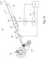
- the sheet-processing machine arrangement chosen as an example initially has, as seen in the transport direction T of the sheets, a sheet feeder 01 in which a first stack 02 of sheets is ready for processing.
- the sheets are preferably rectangular substrates made of paper, cardboard or paperboard. Paper, cardboard and paperboard differ in their respective grammage, i.e. the weight in grams for one square meter of these sheets.
- Paper has a basis weight of between 30 g/m 2 and 150 g/m 2
- cardboard has a basis weight of between 150 g/m 2 and 600 g/m 2
- paperboard has a basis weight of more than 600 g/m 2
- the sheets can also each be a substrate made of a plastic and/or be designed as a thin panel.
- the sheet feeder 01 can also be designed as a magazine feeder having a plurality of first stacks 02.
- a suction head 03 grasps each of the stacked sheets from above and guides these sheets are fed, for example by means of a first oscillating gripper 04 and optionally a transfer drum 34 interacting with the first oscillating gripper 04, in a sequence of sheets separated from one another, for example to a first coating device 05, this first coating device 05 being designed, for example, as a primer application device.
- the first coating device 05 has a transport cylinder 06, designed, for example, as a printing cylinder, and, for example, a printing unit cylinder 07 interacting with this transport cylinder 06 with an application roller 08, preferably in the form of an anilox roller, which is positioned or at least can be positioned on this printing unit cylinder 07, with at least one doctor blade 09 or a chamber doctor blade system 09 extending in the axial direction of the application roller 08 for the optimal metering of a coating material to be applied to the surface of the sheets.
- the transport cylinder 06 transports the sheets held on its outer surface along a curved, in particular circular arc-shaped transport path.
- the first coating device 05 applies the coating material, e.g.
- the sheets are then transferred from the transport cylinder 06 of the first coating device 05, e.g. by means of a first gripper system 11, in particular a first chain conveyor, and e.g. at least one first conveyor belt 12, to a non-impact printing device 13, wherein the first gripper system 11 and the first conveyor belt 12 interact when transferring the sheets to the non-impact printing device 13, in such a way that the first gripper system 11 delivers the sheets to the first conveyor belt 12, which has a linear transport path, wherein the sheets are transferred to the non-impact printing device 13 from the first conveyor belt 12.
- a first gripper system 11 in particular a first chain conveyor, and e.g. at least one first conveyor belt 12
- the first gripper system 11 and the first conveyor belt 12 interact when transferring the sheets to the non-impact printing device 13, in such a way that the first gripper system 11 delivers the sheets to the first conveyor belt 12, which has a linear transport path, wherein the sheets are transferred to the non-impact printing device 13 from the first conveyor belt 12.
- the first conveyor belt 12 is preferably designed as a circulating endless belt.
- a first dryer 14 is provided in the area of the first gripper system 11 for drying the sheets coated in the first coating device 05, wherein this dryer 14 is designed, for example, as a hot air dryer and/or as a dryer that dries by IR radiation or by UV radiation.
- the non-impact printing device 13 generally has at least four inkjet printing devices that can be controlled independently of one another, with each of these inkjet printing devices applying a different printing ink to the side of the sheet that was previously coated, for example, in the first coating device 05, in order to create a preferably multi-colored print image.
- the non-impact printing device 13 preferably has a second conveyor belt 16 so that the sheets are printed on by the inkjet printing devices while they are lying on this second conveyor belt 16.
- the second conveyor belt 16 is preferably designed as a rotating endless belt. However, several conveyor belts 16 can also be provided, for example on two conveyor belts 16 arranged parallel to one another in the transport direction T of the sheets.
- a second dryer 17 that dries the printed sheets is arranged downstream of the non-impact printing device 13, with this second dryer 17 also being able to e.g. B. as a hot air dryer and/or as a dryer drying by IR radiation or by UV radiation.
- the second dryer 17 has a transport device 18 which transports the sheets lying down in a translational manner, ie along a linear transport path. This transport device 18 is in the Fig. 1
- the third conveyor belt 18 is also preferably designed as a continuous endless belt.
- the conveyor device 18 of the second dryer 17 in this example transfers the dried sheets to a suction belt table 19, from which the sheets are transferred to a second coating device 22, for example by means of a second oscillating gripper 21 and, if appropriate, a transfer drum 33 that interacts with the second oscillating gripper 21.
- the second coating device 22 is designed, for example, as a varnishing device, with this second coating device 22 applying a coating material, for example a varnish, in particular to a print image previously created in the non-impact printing device 13.
- the second coating device 22 has, as a conveyor device for The sheet to be transported has a transport cylinder 23, which is designed, for example, as a printing cylinder, with this transport cylinder 23 interacting, for example, with a printing unit cylinder 24 with an application roller 26, preferably in the form of an anilox roller, which is positioned or at least positionable on this printing unit cylinder 24, with at least one doctor blade 27 or a chamber doctor blade system 27 extending in the axial direction of the application roller 26.
- a transport cylinder 23 which is designed, for example, as a printing cylinder, with this transport cylinder 23 interacting, for example, with a printing unit cylinder 24 with an application roller 26, preferably in the form of an anilox roller, which is positioned or at least positionable on this printing unit cylinder 24, with at least one doctor blade 27 or a chamber doctor blade system 27 extending in the axial direction of the application roller 26.
- the sheets are then transported by the transport cylinder 23 of the second coating device 22, for example by means of a second gripper system 28, in particular a second chain conveyor, to a delivery 29, wherein the sheets processed in this machine arrangement described by way of example are deposited by the second gripper system 28 in the delivery, preferably in a second stack 32.
- a third dryer 31 is provided in the area of the second gripper system 28, which dries the sheets coated in the second coating device 22, wherein this third dryer 31 is designed, for example, as a hot air dryer and/or as a dryer that dries by IR radiation or by UV radiation.
- the delivery 29 can also be designed as a multi-stack delivery having a plurality of second stacks 32.
- the Fig. 1 The machine arrangement shown as an example is designed as a digital printing machine for use in an industrial printing process, in particular for the production of printed products in mass production.
- Fig. 2 shows a side view of the suction belt table 19, as it is used in a machine arrangement according to the Fig. 1
- the transport direction T of the sheets is in the Fig. 2 from right to left. 19 individual sheets are fed sequentially to the suction belt table from a Fig. 2 only partially shown transport device 18 at a transport speed of several thousand sheets per hour, e.g. of about 10,000 sheets per hour.
- transport direction T adjacent, ie in the sequence immediately following one another, individual sheets are spaced apart from each other by a gap. This gap is significantly smaller than a length of the sheets extending in the transport direction T of the sheets and is only a few millimeters, e.g. about 20 mm.
- the transport device 18 arranged upstream of the suction belt table 19 in the transport direction T of the sheets belongs to a dryer 17, this dryer 17 being arranged in accordance with the Fig. 1
- the machine arrangement shown by way of example is a second dryer 17, whereby the sheets are transported by this transport device 18 lying, in particular lying on a conveyor belt, in a translatory manner, ie along a linear transport path.
- the suction belt table 19 initially takes over each individual sheet in a conveying plane defined by the transport device 18 arranged upstream of this suction belt table 19 and theoretically extended in the transport direction T of the sheets, whereby this conveying plane is preferably aligned horizontally.
- the conveying plane E19 ( Fig.
- each sheet strikes with its leading edge in the transport direction T against front marks 36 of the oscillating gripper 21 arranged downstream of the suction belt table 19, this oscillating gripper 21 being in the Fig. 1
- the machine arrangement shown as an example is a second oscillating gripper 21. From this oscillating gripper 21, each sheet is transferred individually to a transfer drum 33 that interacts with this oscillating gripper 21. The sheets are completely braked at the front lays and aligned in register.
- the suction belt table 19 has a sub-shingling device for sheets to be transported.
- the sub-shingling device has a preferably over the entire width of the sheets, ie transversely to the transport direction T of the sheets, the so-called blow box 37, wherein in the blow box 37, on the side thereof facing the conveying plane E19 of the suction belt table 19, a plurality of blow nozzles are arranged one behind the other in the transport direction T of the sheets.
- at least two rows of a plurality of blow nozzles arranged next to one another are arranged one behind the other in the transport direction T of the sheets and in each case transversely to the transport direction T of the sheets.
- a respective blowing direction of the blow nozzles is directed essentially parallel to the conveying plane E19 of the suction belt table 19, against the transport direction T of the sheets.
- the respective blowing direction of the blow nozzles is determined, for example, by at least one guide surface which channels the flow of the blowing air and is arranged and/or molded onto the respective blow nozzle.
- the respective guide surface is, for example, on the side of the blow box 37 facing the conveying plane E19 of the suction belt table 19. B. designed as a ramp protruding from this blow box 37.
- Blowing air flowing out of the respective blow nozzles is preferably controlled by adjustable pneumatic valves, e.g.
- valves are controlled, e.g., by a preferably digital control unit 71 that processes a program.
- the valves are switched, e.g., by the control unit 71 in particular in a cycle, wherein a cycle duration and/or a cycle frequency is preferably set depending on the advance of the sheets fed to the suction belt table 19.
- Valves controlled in a cycle by a preferably digital control unit 71 are also referred to as cycle valves.
- a bulkhead plate 38 is arranged in a region between the conveying plane E19 of the suction belt table 19 and the side of the blow box 37 facing this conveying plane E19 in front of the first blow nozzle or the first row of blow nozzles, wherein the bulkhead plate 38 protects the front edge of a subsequent sheet, ie a sheet which directly follows a sheet lifted by the blowing air from at least one of the blow nozzles of the blow box 37, against the 37 arranged blow nozzles.
- the arch raised by at least one of the blow nozzles or blow nozzle rows of the blow box 37 from the conveying plane E19 of the suction belt table 19 channels the blowing air flowing out of the at least one blowing nozzle of the blow box 37 and guides this blowing air over the surface of the partition plate 38 facing the blow box 37.
- the partition plate 38 preferably has a concave curvature at its end located in the blowing direction, this curvature giving the blowing air an outflow direction facing away from the conveying plane E19 of the suction belt table 19.
- the leading edge of a sheet which directly follows a sheet lifted by the blowing air from at least one of the blowing nozzles remains unaffected until the lifted sheet, through its own movement progress or advance directed in the transport direction T, exposes with its rear end the blowing nozzle or row of blowing nozzles which this sheet first reaches in its transport direction T.
- the blowing air of the blowing nozzle or row of blowing nozzles in question is switched off by means of the respective associated valve depending on the progress of movement or feed of the sheet that is currently lifted by the conveying plane E19 of the suction belt table 19 and directly precedes a sheet located between the bulkhead plate 38 and the conveying plane E19 of the suction belt table 19.
- a sheet lifted by the blowing nozzles or blowing nozzle rows is lifted due to the suction effect (Venturi effect) caused by the respective blowing air above the conveying plane E19 of the suction belt table 19 to a certain floating height, e.g. measured by a distance from the side of the blow box 37 facing the conveying plane E19 of the suction belt table 19, whereby this floating height depends on the intensity of the respective blowing air and/or on the mass of the sheet in question and/or on the transport speed of the sheet in question.
- a certain floating height e.g. measured by a distance from the side of the blow box 37 facing the conveying plane E19 of the suction belt table 19, whereby this floating height depends on the intensity of the respective blowing air and/or on the mass of the sheet in question and/or on the transport speed of the sheet in question.
- a support plate supporting the raised sheet is preferably provided in the area between the conveying plane E19 of the suction belt table 19 and the side of the blow box 37 facing this conveying plane E19, wherein the support plate, e.g. arranged at an acute angle to the side of the blow box 37 facing the conveying plane E19 of the suction belt table 19, is designed e.g. in the form of an air-permeable grid.
- the sheet lifted by the suction of the blowing air and placed against the support plate is guided there in a smooth movement, i.e. without fluttering, in its transport direction T along this support plate.
- openings 39 In the conveying plane E19 of the suction belt table 19, preferably several openings 39 ( Fig. 3 ) through which air flows under the currently raised sheet to equalize the pressure. These openings 39 are, for example, circular with a diameter in the range of a few millimeters.
- suction chambers 41 are arranged below the conveying plane E19 of the suction belt table 19, the respective flow effects of which can be controlled. These suction chambers 41 are preferably arranged one behind the other in the transport direction T of the sheets and their respective pressure can be switched, for example, individually and independently of one another by means of a suction device controlled by the control unit 71.
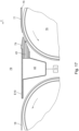
- Fig. 3 shows in a top view the Fig. 2
- the transport direction T of the sheets is as shown in the Fig. 2 from right to left.
- individual sheets are fed sequentially to the suction belt table 19 by a transport device that transports the sheets in a translatory manner, in particular by a transport device belonging to a dryer 17.
- the sheets are each located on at least one conveyor belt 18, preferably on several, e.g. on two conveyor belts 18 arranged parallel to one another in the transport direction T of the sheets.
- These conveyor belts 18 are each designed, for example, as endlessly rotating flat belts or flat belts.
- a guide device 42 extending transversely to the transport direction T of the sheets is arranged, preferably with several lifting nozzles 43 arranged in at least one row.
- at least one transfer belt 44 which is designed, for example, as a rotating flat belt arranged in the middle area of the conveying plane E19 of the suction belt table 19 and also preferably as a suction belt, the suction belt having a perforation at least in sections.
- two consecutive bends 46; 47 are shown, the first bend 46 being arranged in the effective area of the transfer belt 44 and the second bend 47 being arranged at a short distance of less than one sheet length in the transport direction T of the sheets after the transfer belt 44.
- the conveying plane E19 of the suction belt table 19 for example symmetrically to its center line M, spanning the distance between the bends 46; 47, preferably two jump belts 48 arranged parallel to one another in the transport direction T of the sheets, for example in the form of endless belts that each run around and are preferably each designed as a suction belt.
- the skid belts 48 are pivotally mounted at their rear end in the transport direction T of the sheets, which is thus reached first by a sheet fed in, in particular, by the transfer belt 44, so that these skid belts 48 extend obliquely upwards from the previous conveying plane E19 of the suction belt table at an acute angle opening in the transport direction T of the sheets. 19 can be swung out and in their extended operating state form a raised ramp for the sheets to be transported.
- the skid belts 48 are shown in their normal operating state, i.e. not swung out and preferably flush with the rest of the conveyor plane E19 of the suction belt table 19.
- nozzles 49 are arranged at least in the respective longitudinal edge areas of the area of the conveyor plane E19 of the suction belt table 19 spanned by the skid belts 48.
- This arrangement of the venturi nozzles begins in the transport direction T of the sheets at a distance of e.g. less than 200 mm, preferably less than 100 mm behind the at least one lifting nozzle 43.
- a blower 51 extending transversely to the transport direction T of the sheets is arranged at a distance A51 ( Fig. 2 and 3 ), this catch blower 51 having a plurality of blow nozzles which are arranged in a row extending over the entire width B19 of the conveying plane E19 of the suction belt table 19.
- a switching area 52 with several suction holes 53 begins, extending in the transport direction T of the sheets.
- the suction holes 53 in the switching area 52 form and open a fluidic connection to at least one of the preferably several suction chambers 41 each arranged below the conveying plane E19 of the suction belt table 19, wherein these suction chambers 41 are switched or at least switchable by the control unit 71, in particular individually and independently of one another in their respective pressure, so that in this switching area 52 by means of the suction holes 53 and by the respective setting of the pressure in the relevant suction chamber 41 in the conveying plane E19 of the suction belt table 19, a negative pressure can be set or at least adjusted.
- the suction holes 53 arranged in the switching area 52 are, for example, symmetrical to the center line M of the conveying plane E19 of the Suction belt table 19 are arranged in several rows, e.g.
- At least one feed belt 54 designed in particular as a suction belt, adjoins the switching area 52, e.g. in an overlapping manner with the switching area 52, the suction belt having a perforation at least in sections, the at least one feed belt 54 extending in the transport direction T of the sheets preferably to below the blow box 37 of the shingling device.
- the at least one feed belt 54 is preferably designed as a rotating endless belt.
- several, e.g. two, feed belts 54 are provided, e.g. symmetrical to the center line M of the conveying plane E19 of the suction belt table 19.
- brake belts 56 which are arranged symmetrically to their center line M and are preferably designed as a continuous endless belt, which have the function of reducing the respective transport speed of the sheets fed in before they are transferred to a transport device immediately downstream of the suction belt table 19, for example to an oscillating gripper 21.
- the sheets which are preferably reduced in their respective transport speed, are then gripped by a rotating or at least rotatable suction roller 57, which is subjected to negative pressure by a suction device, during their further movement in the transport direction T, wherein this suction roller 57 is arranged transversely to the transport direction T of the Sheets preferably extend at least over the entire width of the sheets or over the entire width B19 of the suction belt table 19. Then each of the sheets, one after the other and individually held by the suction roller 57, reaches with its front edge in the transport direction T, i.e. its front edge, e.g. to the front lays 36 of the oscillating gripper 21 arranged immediately downstream of the suction belt table 19.
- the sheets which were previously transported individually, one behind the other, with a gap between them, are transferred into an shingled stream before these sheets are transferred to a transport device arranged immediately downstream of the suction belt table 19, e.g. to an oscillating gripper 21, in order to then be rotated in a machine arrangement having this suction belt table 19, e.g. designed as a digital printing machine, to a coating device 22, e.g. B. to a coating device 22 designed as a painting device and to be transported through this.
- a transport device arranged immediately downstream of the suction belt table 19, e.g. to an oscillating gripper 21, in order to then be rotated in a machine arrangement having this suction belt table 19, e.g. designed as a digital printing machine, to a coating device 22, e.g. B. to a coating device 22 designed as a painting device and to be transported through this.
- a malfunction can occur for various reasons in a processing station downstream of the suction belt table 19, e.g. designed as a coating device 22.
- a serious malfunction in such a processing station results in the transfer of sheets to the transport device downstream of the suction belt table 19 having to be abruptly interrupted.
- This operating case forms a stopper.
- sheets in transport in the machine arrangement must be collected and stacked very quickly and effectively.
- a suction belt table 19 with a catching device 58 is proposed, with which catching device 58 in a sequence successive individual sheets in front of their transfer to a transport device arranged downstream of the suction belt table 19, they are caught and stacked on the suction belt table 19.
- this suction belt table 19, which preferably has a shingling device, is arranged in the transport direction T of the sheets after a dryer 17 arranged downstream of a non-impact printing device 13.
- the suction belt table 19 is arranged in a machine arrangement at a point at which the sheets are transferred from a linear transport path arranged immediately upstream of this suction belt table 19 to a curved, in particular circular-arc-shaped, transport path arranged immediately downstream of this suction belt table 19.
- the proposed catching device 58 has a slider crank mechanism, the coupling of which has at least one stop surface 66 for the sheets to be caught. Details of the catching device 58 and its functionality are explained below using the Fig. 4 to 6 described.
- Fig. 4 shows an example of a side view of the catching device 58.
- This catching device 58 is arranged, as long as it is inactive, e.g. not actuated by the control unit 71, below the conveying plane E19 of the suction belt table 19, preferably approximately one sheet length extending in the transport direction T of the sheets from a line drawn by the catching blower 51 perpendicular to the conveying plane E19 of the suction belt table 19 corresponding to the distance A51 at the end of the switching area 52 of this suction belt table 19 having suction holes 53.
- the catching device 58 has a drive 59, which is preferably designed as a double-acting pneumatic cylinder 81, the cylinder piston 82 of which can be pressurized with compressed air on both sides ( Fig. 8 ).
- a bidirectional linearly movable piston rod 61 of the pneumatic cylinder 81 is connected to a crank 62 designed as an angle lever by forming a pivot point G61, the crank 62 being rotatably mounted in a pivot point D62 fixed in the suction belt table 19.
- the Crank 62 designed as an angle lever, has a short lever and a lever that is longer than this short lever, the short lever connecting the articulation point G61, at which the piston rod 61 of the pneumatic cylinder 81 is connected to the crank 62, to the pivot point D62 of the crank 62.
- the crank 62 is in turn connected to a coupling 63, forming an articulation point G62.
- the longer lever of the crank 62 extends between its pivot point D62 and the articulation point G62, at which the crank 62 is connected to the coupling 63.
- the coupling 63 and the crank 62 driving the coupling 63 form a slider-crank mechanism in their interaction, an end point E2 of the coupling 63 facing away from the drive 59 of the catching device 58 being bidirectionally linearly movable along a path 64 arranged parallel to the conveying plane E19 of the suction belt table 19.
- the end point E2 of the coupling 63 facing away from the drive 59 of the catching device 58 and the pivot point D62 of the crank 62 therefore lie on a straight line G64 connecting them, this straight line G64 running parallel to the conveying plane E19 of the suction belt table 19.
- the coupling 63 has at least one stop surface 66 for sheets to be caught in an area between its end point E1 facing the drive 59 of the catching device 58 and the articulation point G62 at which the crank 62 is connected to the coupling 63.
- the stop surface 66 in question is therefore preferably a component of the coupling 63.
- the stop surface 66 in question is preferably made of a plastic, e.g. from a polyamide (abbreviation PA) or from a thermoplastic such as e.g. polyoxymethylene (abbreviation POM).
- the slider crank mechanism has a centric slider crank, which means that the three Fig. 4 shown sections G62-D62, G62-E2 and G62-E1 are each of the same length and the end points E1; E2 of the coupling 63 together with the joint point G62 arranged between them all lie on a straight line G63 connecting the end points E1; E2 of the coupling 63.
- the short lever and the longer lever of the crank 62 are designed in their length ratio to one another in such a way that they translate a movement triggered by the drive 59 of the arresting device 58 and acting on the coupling 63 into a faster speed.
- FIG. 2 and 5 show the catching device 58 in its inactive, ie unactuated starting position or parking position, in which the at least one stop surface 66 formed on the coupling 63 is arranged below the conveying plane E19 of the suction belt table 19.
- the sheets can pass the suction belt table 19 in its conveying plane E19 unhindered, which in the Fig. 5 is indicated by two consecutive directional arrows.
- the piston rod 61 of the pneumatic cylinder 81 forming the drive 59 of the safety device 58 is extended by a corresponding application of compressed air to this pneumatic cylinder 81 and the end point E2 of the coupling 63 facing away from the drive 59 of the safety device 58 takes up its position on the track 64 furthest from the drive 59 of the safety device 58.
- the Fig. 6 and 7 show the catching device 58 in its catching position.
- the at least one stop surface 66 preferably formed on the coupling 63, penetrates through a corresponding, e.g. slot-shaped opening 67 ( Fig. 3 ) the conveying plane E19 of the suction belt table 19 and, by means of a pivoting movement, positions itself from a position previously inclined at a preferably acute angle to the conveying plane E19 of the suction belt table 19, preferably perpendicular to this conveying plane E19 ( Fig.
- Fig. 7 shows an excerpt from the Fig. 2 with skid belts 48, which are shown in their operating state protruding obliquely upwards from the previous conveyor level E19 of the suction belt table 19 at an acute angle opening in the transport direction T of the sheets, as well as with a catch blower 51 activated, for example, by the control unit 71, the activation of which in the Fig. 7 is indicated by a blowing direction arrow directed towards the conveying plane E19 of the suction belt table 19.
- the catching device 58 is switched to its catching position by the drive 59 of the catching device 58 being automatically, in particular program-controlled, actuated by a control unit 71, usually by the further control unit 71 that preferably controls all functions of the suction belt table 19.
- This control unit 71 also controls, for example, the valves of the blow box 37 ( Fig. 2 ).
- the transport speed of the sheets can be reduced, for example, by Catching device 58 in the transport direction T of the sheets, transport devices arranged upstream of the catch 58 reduce their respective transport speed. Even if the transport speed of a transport device arranged upstream of the catch 58 in the transport direction T of the sheets is not immediately reduced when the catch 58 is actuated, e.g.
- the negative pressure set in the relevant suction chamber 41 by means of a suction device 72 controlled by the control unit 71 is switched off in any case, this suction chamber 41 being fluidically connected to the relevant switching area 52 by means of the suction holes 53 formed in the conveying plane E19 of the suction belt table 19 and at least partially overlapping with a floor plan of the stack of sheets to be caught.
- the at least one stop surface 66 of the catch 58 is then shot into a sheet gap between the rear edge of a previous sheet and a front edge of a first subsequent sheet to be caught.
- control unit 71 actuates at least one pneumatic switching valve 86, preferably two pneumatic switching valves 86; 87 simultaneously, so that the piston rod 61 of the pneumatic cylinder 81 forming the drive 59 of the catching device 58 is retracted.
- this pneumatic cylinder 81 has a bottom chamber 68 and a bearing chamber 69 separated from the bottom chamber 68 by a cylinder piston 82 firmly connected to the piston rod 61, wherein a first pneumatic switching valve 86 is connected to the bottom chamber 68 and a second pneumatic switching valve 87 is connected to the bearing chamber 69.
- These two switching valves 86; 87 are each controlled by the control unit 71 of the catching device 58.
- the bottom chamber 68 can have barometric pressure.
- the bottom chamber 68 can have a differential pressure greater than the barometric pressure and less than the pressure in the bearing chamber 69.
- the piston rod 61 of the pneumatic cylinder 81 forming the drive 59 of the catching device 58 is retracted by pressurizing the bearing chamber 69, e.g. with 7 bar.
- the cylinder piston 82 of the pneumatic cylinder works against compressed air pre-pressurized in the base chamber 68, e.g. with 2 bar, which can escape in a throttled manner via the open pneumatic switching valve 86 of the base chamber 68 and, if necessary, via a subsequent throttle valve 91.
- the proposed slider-crank mechanism it is possible to bring at least one stop surface 66 of the catching device 58 into the catching position even at a high sheet transport speed of several thousand sheets per hour, e.g. of around 10,000 sheets per hour, through a sheet gap measuring only around 20 mm, for example.
- the reaction time achievable with the proposed slider-crank mechanism thus significantly exceeds the switching times of simple folding and/or sliding mechanisms which are driven, for example, by switching magnets or directly, i.e. gearless, by a pneumatic cylinder 81.
- a further advantage of the solution found is that the proposed slider-crank mechanism is comparatively simple and space-saving.
- Sheets are arranged one behind the other, with at least one of these processing stations having a transport device 18 which transports the sheets lying down along a linear transport path, with this transport device 18 being designed to transport individual sheets which follow one another directly in succession in a sequence, each one spaced apart from one another by a gap, with a suction belt table 19 being arranged downstream of this transport device 18 which transports the sheets lying down along a linear transport path, the suction belt table 19 having a catching device 58 with a catching position assumed as a result of an actuation for individual sheets which follow one another in a sequence, the catching device 58, in its catching position, catching and stacking sheets fed to the suction belt table 19 by the transport device 18 which transports the sheets lying down along a linear transport path and is arranged upstream of the suction belt table 19, on the suction belt table 19 before they are respectively transferred to a transport device arranged downstream of the suction belt table 19.
- a control unit 71 provided for the suction belt table 19 actuates the catching device 58 depending on a fault that has occurred in a processing station downstream of the suction belt table 19 such that the catching device 58 assumes its catching position.
- the transport device 18 arranged upstream of the suction belt table 19, which transports the sheets lying down along a linear transport path, belongs to a dryer 17.
- This dryer 17 is arranged downstream of a processing station designed as a non-impact printing device 13, for example.
- the suction belt table 19 is also preferably arranged upstream of a processing station designed as a coating device 22, in particular a varnishing device.
- the coating device 22 has a transport cylinder 23 as a transport device for sheets to be transported, with this transport cylinder 23 preferably interacting with a printing unit cylinder 24 with an application roller 26 that is or can at least be positioned on this printing unit cylinder 24, with at least one doctor blade 27 or a chamber doctor blade system 27 extending in the axial direction of the application roller 26.
- This machine arrangement is the sheets with a Transport speed preferably of several thousand sheets per hour, in particular of about 10,000 sheets per hour.
- the transport device 18 arranged upstream of the suction belt table 19, which transports the sheets lying down along a linear transport path, is designed to transport the individual sheets which follow one another in a sequence, each with a sheet gap preferably measuring about 20 mm.
- a suction belt table 19 for sheet-shaped substrates to be transported lying individually the suction belt table 19 being arranged between a transport device arranged upstream in the transport direction T of the substrates and a correspondingly downstream transport device, the suction belt table 19 having a catching device 58 with a catching position assumed as a result of its actuation for individual substrates which follow one another in a sequence, the catching device 58 in its catching position catching substrates fed to the suction belt table 19 from the upstream transport device on the suction belt table 19 before they are respectively transferred to the transport device arranged downstream of the suction belt table 19, i.e. preventing them from moving forward in the transport direction T and stacking them.
- the transport device upstream of the suction belt table 19 has a translatory transport path for the sheet-shaped substrates to be transported individually lying down and/or the transport device downstream of the suction belt table 19 has a rotary transport path or a translatory transport path for the sheet-shaped substrates to be transported.
- a control unit 71 in particular a digital one, is provided, wherein this control unit 71 actuates the catching device 58 depending on a disturbance that has occurred along the transport path belonging to the transport device downstream of the suction belt table 19 in such a way that the catching device 58 assumes its catching position.
- the catching device 58 has at least one pivotable stop surface 66 for substrates to be caught, wherein the stop surface 66 in question can be pivoted in the direction of the Control unit 71, in the unactuated state of the catching device 58, it is arranged below a conveying plane E19 of the suction belt table 19, and in the state of the catching device 58 actuated by the control unit 71, it is pivoted through an opening 67 in the conveying plane E19 of the suction belt table 19 and positioned perpendicular to this conveying plane E19, so that substrates transported on the suction belt table 19 strike against the at least one raised stop surface 66 protruding from the conveying plane E19 of the suction belt table 19.
- the catching device 58 has a slider-crank mechanism, the slider-crank mechanism having a coupling 63 and a crank 62 interacting with the coupling 63, the crank 62 being driven by a drive 59.
- the crank 62 is rotatably mounted in a pivot point D62 arranged in a fixed position in the suction belt table 19, the crank 62 being designed as an angle lever and having a short lever and a lever that is longer than this short lever, the short lever connecting a pivot point G61, at which the drive 59 engages the crank 62, to the pivot point D62 of the crank 62, the longer lever of the crank 62 extending between its pivot point D62 and a pivot point G62, at which the crank 62 is connected to the coupling 63.
- the length ratio of the short lever and the longer lever of the crank 62 to one another is such that they translate a movement acting on the coupling 63 from the drive 59 of the catching device 58 into a faster speed.
- the transmission ratio i into a faster speed is preferably at least 1:5.
- An end point E2 of the coupling 63 facing away from the drive 59 of the catching device 58 is bidirectionally linearly movable along a path 64 arranged parallel to the conveying plane E19 of the suction belt table 19, wherein the end point E2 of the coupling 63 facing away from the drive 59 of the catching device 58 and the pivot point D62 of the crank 62 are arranged on a straight line G64 connecting these two points, wherein this straight line G64 runs parallel to the conveying plane E19 of the suction belt table 19.
- the at least one stop surface 66 for substrates to be caught is in a region between an end point E1 of the coupling 63 facing the drive 59 of the catching device 58 and the articulation point G62 at which the crank 62 is connected to the coupling 63. is connected.
- the slider crank mechanism preferably has a central slider crank, in which the three sections G62-D62; G62-E2; G62-E1 are each of the same length and the end points E1; E2 of the coupling 63 together with the articulation point G62 arranged between them are all arranged on a straight line G63 connecting the end points E1; E2 of the coupling 63.
- the drive 59 of the catching device 58 is advantageously designed as a double-acting pneumatic cylinder 81, this pneumatic cylinder 81 having a bottom chamber 68 and a bearing chamber 69 separated from the bottom chamber 68 by a cylinder piston 82 firmly connected to its piston rod 61.
- the bearing chamber 69 is arranged at that end of the pneumatic cylinder 81 which faces the articulation point G61 at which the drive 59 engages the crank 62.
- the bottom chamber 68 is arranged at the end of the pneumatic cylinder 81 that faces away from the articulation point G61 at which the drive 59 engages the crank 62.
- a first pneumatic switching valve 86 is connected to the bottom chamber 68 and a second pneumatic switching valve 87 is connected to the bearing chamber 69, whereby these two switching valves 86; 87 are each controlled by the control unit 71 of the catching device 58.
- the bottom chamber 68 either has barometric pressure or the bottom chamber 68 has a differential pressure greater than the barometric pressure and less than the pressure in the bearing chamber 69.
- the piston rod 61 of the pneumatic cylinder 81 is retracted by applying pressure to the bearing chamber 69, e.g. with 7 bar.
- the cylinder piston 82 of the pneumatic cylinder 81 works against compressed air pre-pressurized in the bottom chamber 68, for example with 2 bar, wherein this compressed air is provided from a compressed air source 93 connected to the bottom chamber 68.
- a suction belt table 19 for the horizontal transport of individual sheet-shaped substrates in a conveyor plane E19 wherein the suction belt table 19 has a catching device 58 and at least one skid belt 48, wherein the catching device 58 and the at least one skid belt 48 are each supported by a Control unit 71 controlled, are designed to assume one of two different operating states, wherein with respect to the catching device 58 and the at least one skid belt 48, the first operating state is an inactive operating state and the second operating state is an activated operating state, wherein the catching device 58 in its activated state has at least one stop surface 66 set up perpendicular to the conveying plane E19 of the suction belt table 19 for substrates to be caught, wherein the at least one skid belt 48 is arranged in the transport direction T of the substrates by at least one substrate length extending in the transport direction T of the substrates in front of the at least one stop surface 66 set up perpendicular to the conveying plane E19 of the suction belt table
- the suction belt table 19 is arranged between a transport device arranged upstream in the transport direction T of the substrates and a correspondingly downstream transport device, wherein the transport device arranged upstream of the suction belt table 19 has a translatory transport path for the sheet-shaped substrates to be transported individually and/or the transport device arranged downstream of the suction belt table 19 has a rotary transport path or a translatory transport path for the sheet-shaped substrates to be transported.
- a catching blower 51 with several blow nozzles arranged in a row extending transversely to the transport direction T of the substrates is arranged, wherein the catching blower 51 in its activated state blows air from its blow nozzles e.g. vertically in the direction of the conveying plane E19 of the suction belt table 19 blows.
- the control unit 71 actuates the catching device 58 as a function of a fault that has occurred along the transport path belonging to the transport device downstream of the suction belt table 19 in such a way that the catching device 58 sets up its at least one stop surface 66 for substrates to be caught perpendicular to the conveying plane E19 of the suction belt table 19 and/or this control unit 71 actuates the at least one skid belt 48 as a function of the fault that has occurred along the transport path belonging to the transport device downstream of the suction belt table 19 in such a way that the at least one skid belt 48 is pivoted out of the conveying plane E19 of the suction belt table 19 at an acute angle obliquely upwards and/or this control unit 71 actuates the catching blower 51 as a function of the fault that has occurred along the transport path belonging to the transport device downstream of the suction belt table 19 in such a way that the catching blower 51 blows air from its Blow nozzles in the direction of the conveying plane E19 of
- the suction belt table 19 is preferably designed such that in the transport direction T of the substrates, after the catching device 58, above the conveying plane E19 of the suction belt table 19, a blow box 37 of an under-shingling device belonging to the suction belt table 19 is arranged.
- a guide device 42 with several lifting nozzles 43 extending transversely to the transport direction T of the substrates is arranged.
- At least one suction chamber 41 is arranged, the respective pressure of the suction chamber 41 being set or at least adjustable by the control unit 71, the control unit 71 being able to control the A negative pressure is set or at least adjustable through suction bores 53 formed in the conveying plane E19 of the suction belt table 19 to the relevant suction chamber 41 in the conveying plane E19 of the suction belt table 19.
- the negative pressure set in the conveying plane E19 of the suction belt table 19 by means of the suction chamber 41 is switched off in the event of a fault occurring along the transport route belonging to the transport device downstream of the suction belt table 19.
- the control unit 71 is preferably designed such that it reduces a transport speed of the substrates at least in the transport device upstream of the catching device 58 in the transport direction T of the substrates.
- two jump belts 48 arranged parallel to one another in the form of each rotating endless belts are provided in the transport direction T of the sheets, these two jump belts 48 being arranged symmetrically to the center line M of the conveying plane E19 of the suction belt table 19.
- a pneumatic drive 59 controlled by the control unit 71 actuates the catching device 58.
- a stopper when a stopper is in operation, due to the high transport speed of several thousand sheets transported in the conveying plane E19 of the suction belt table 19 per hour, e.g. of around 10,000 sheets per hour, and the relatively small gap of e.g.
- a cylinder piston 82 in a pneumatic cylinder 81 exerts such a large force impulse on the inner Stops of this pneumatic cylinder 81 are such that these stops are worn out in a very short time and are thus destroyed.
- this pneumatic cylinder 81 has sufficient wear resistance and thus as unrestricted an operating life as possible when used as described.
- a pneumatic circuit be provided for the operation of the double-acting pneumatic cylinder 81 of the catching device 58, which pneumatic circuit controls the movement of the cylinder piston 82 in such a way that a positive acceleration is set for the cylinder piston 82 in a first half of its stroke and a negative acceleration is set in a second half of its stroke following the first half.
- This pneumatic cylinder 81 has a base chamber 68 and a bearing chamber 69 separated from the base chamber 68 by the cylinder piston 82, the cylinder piston 82 being firmly connected to the piston rod 61.
- the bearing chamber 69 is arranged at that end of the pneumatic cylinder 81 which faces the articulation point G61 at which the drive 59 engages the crank 62.
- the bottom chamber 68 is arranged at the end of the pneumatic cylinder 81 that faces away from the articulation point G61, at which the drive 59 engages the crank 62.
- the cylinder piston 82 preferably has an end position damping element 83; 84 on both sides.
- the pneumatic circuit described in detail below implements a controlled acceleration phase and a controlled braking phase over the entire stroke of the cylinder piston 82 by changing a dynamic pressure equilibrium in the two chambers 68; 69 of the pneumatic cylinder 81.
- the pneumatic circuit has a first pneumatic switching valve 86 and a second pneumatic switching valve 87, wherein both switching valves 86; 87 are each preferably electrically operated by the control unit 71. Both switching valves 86; 87 are in one of their switching positions each connected to their respective compressed air source 93.
- Fig. 8 shows the operating position of the pneumatic cylinder 81 in which the piston rod 61 of the pneumatic cylinder 81 forming the drive 59 of the catching device 58 is retracted and the catching device 58 is thus activated, which means that the stop surface 66 of the catching device 58 is positioned in the conveying plane E19 of the suction belt table 19.
- At least the switching valve 86 for the bottom chamber 68 is preferably preceded by a pressure reducer 88 in order to build up a defined initial counterpressure in the bottom chamber 68 when the compressed air flows out.
- a pressure reducer 89 can also be preceded by the switching valve 87 for the storage chamber 69.
- a throttle valve 91 is arranged downstream of the switching valve 86 of the base chamber 68 in order to use this throttle valve 91, the cross-section of which is preferably adjustable, to influence the outflow speed of the compressed air from the base chamber 68 and thus the dynamic pressure curve in the pneumatic cylinder 81 and thus the speed of the cylinder piston 82.
- a throttle valve 92 is also arranged in the air outlet from the bearing chamber 69 of the pneumatic cylinder 81 in order to limit the speed of the cylinder piston 82.
- the throttle valve 91 of the base chamber 68 and, if applicable, the throttle valve 92 of the bearing chamber 69 are only used when compressed air flows out of the respective chamber 68; 69 into the atmosphere.
- the bearing chamber 69 of the pneumatic cylinder 81 is preferably depressurized, i.e. there is a pressure in it, e.g. equal to the barometric pressure.
- the bearing chamber 69 of the pneumatic cylinder 81 is subjected to a pressure greater than the barometric pressure via the pressure reducer 89 that may be connected to it, e.g. with a pressure that corresponds to the pressure in the bottom chamber 68, i.e. preferably with a pressure of e.g. 2 bar. If the pressure set in both chambers 68; 69 is the same, the cylinder piston 82 is held in a stable end position.
- the bottom chamber 68 which is pre-tensioned with compressed air, e.g. at 2 bar, an air mass that can be controlled via the pressure is made available, which is required to brake the travel movement of the cylinder piston 82 that occurs when the catching device 58 is activated.
- the catching device 58 is activated by shooting its at least one stop surface 66 into a sheet gap between the trailing edge of a previous sheet and the leading edge of a first subsequent sheet to be caught by the two switching valves 86; 87 being actuated by the control unit 71, in particular simultaneously.
- the storage chamber 69 is supplied with compressed air from its compressed air source 93 at more than 5 bar, in particular with a pressure of e.g. B.
- the braking effect sets in in such a way that the movement of the cylinder piston 82 initially experiences a very large acceleration with resulting speed, before this movement of the cylinder piston 82 is largely braked at the end by the actively clamped air column and only a remaining residual speed of less than, for example, 1 0% of the previously achieved maximum possible speed is braked at the end position damping element 83 of the pneumatic cylinder 81.
- the safety catch 58 is activated, the cylinder piston 82 is accelerated over the first half of its stroke and braked over the second half. In the first half of its stroke, the cylinder piston 82 reaches its maximum possible speed.
- the cylinder piston 82 arrives at its respective end position at zero speed. In real operation, however, this is not achieved. Therefore, the small amount of residual energy still present must be dissipated at the respective end position damping element 83; 84.
- This very rapid movement of the cylinder piston 82 is transmitted by the crank 62 to the preferably centrically positioned
- the coupling 63 arranged in the slide crank position is transmitted with a high gear ratio.
- the pneumatic circuit described and the pressure setting values given as examples make it possible to bring at least one stop surface 66 of the catching device 58 into a catching position even at the high transport speed of the sheets mentioned above through the very narrow sheet gap mentioned above.
- the solution shown advantageously avoids high impact loads and load peaks in the entire kinematic system. This is because the clamped air column, which dampens the drive movement of the cylinder piston 82 at the end, particularly in the base chamber 68, effectively prevents the cylinder base from being destroyed.
- a safe end position of the cylinder piston 82 in its retracted state is achieved without additional mechanical elements and therefore without additional costs.
- the pressure reduction in the storage chamber 69 also saves energy and reduces any leakage.
- Fig. 9 to 12 illustrate once again, by way of example, in a diagram over the time t plotted on the abscissa, the dynamic behavior of some physical variables with reference to the cylinder piston 82 of the pneumatic cylinder 81 during a switching process when the catching device 58 of the respective suction belt table 19 is moved from its starting position to its catching position, in particular actuated by a control signal from the control unit 71.
- Fig. 9 shows a change in position of the cylinder piston 82 between its two end positions in the pneumatic cylinder 81. A travel z and thus the stroke of the cylinder piston 82 is shown here, for example, as 10 mm.
- Fig. 9 shows a change in position of the cylinder piston 82 between its two end positions in the pneumatic cylinder 81. A travel z and thus the stroke of the cylinder piston 82 is shown here, for example, as 10 mm.
- FIG. 10 shows, by way of example, the speed v of the cylinder piston 82 during its movement along the travel z.
- Fig. 11 shows as an example the corresponding acceleration a with which the cylinder piston 82 executes its movement along the travel z.
- Fig. 12 The piston force F exerted by the cylinder piston 82 is then shown as an example.
- a suction belt table 19 is produced for the horizontal transport of individual sheet-shaped substrates in a conveyor plane E19, wherein the suction belt table 19 has a catching device 58 with at least one stop surface 66 for substrates to be caught, which is set up in its catching position in the conveyor plane E19 of the suction belt table 19, wherein this at least one stop surface 66 is set up from an inactive starting position of the catching device 58 by a double-acting pneumatic cylinder 81 by a movement of its cylinder piston 82 into the catching position, wherein this pneumatic cylinder 81 has a bottom chamber 68 and a storage chamber 69 separated from the bottom chamber 68 by the cylinder piston 82, wherein a pneumatic circuit is provided for controlling the movement of the cylinder piston 82, wherein the pneumatic circuit has a first pneumatic switching valve 86 connected to the bottom chamber 68 and a second pneumatic switching valve connected to the storage chamber 69.
- the catching device 58 has a slider crank mechanism driven by the cylinder piston 82 of the pneumatic cylinder 81 as described above. The movement of the cylinder piston 82 is controlled by the control unit 71 such that a positive acceleration is set for the cylinder piston 82 in a first half of its stroke and a negative acceleration in a second half of its stroke following the first half.
- a pressure reducer 88 is connected upstream of at least the first switching valve 86 connected to the base chamber 68. Also connected downstream of at least the first switching valve 86 connected to the base chamber 68 is, for example, a throttle valve 91 whose opening cross-section is preferably adjustable.
- the opening cross-section of the throttle valve 91 is, for example, B. set by the control unit 71 in such a way that the movement of the cylinder piston 82 at the end of the second half of its stroke has a residual speed of less than 10% of the maximum speed previously reached in the first half of its stroke.
- the cylinder piston 82 preferably has an end position damping element 83; 84 on both sides, wherein the end position damping element 83; 84 at the end of the second half of its stroke stroke is braked at the relevant end position damping element 83; 84.
- the control unit 71 switches the first switching valve 86 connected to the bottom chamber 68 into a position that diverts the air mass from the bottom chamber 68 and at the same time the second switching valve 87 connected to the bearing chamber 69, so that the bearing chamber 69 is subjected to compressed air at a pressure of more than 5 bar.
- the suction belt table 19 has in its conveying plane E19 a switching area 52 extending in the transport direction T of the sheets with a plurality of suction bores 53, wherein preferably a plurality of suction chambers 41 are arranged below the conveying plane E19 of the suction belt table 19, the respective flow-related effects of which can be controlled.
- These suction chambers 41 are preferably arranged one behind the other in the transport direction T of the sheets and in particular are switched or at least switchable individually and independently of one another in terms of their respective pressure.
- the suction holes 53 in the switching area 52 form a fluidic connection to at least one of the preferably several suction chambers 41 each arranged below the conveying plane E19 of the suction belt table 19, wherein in this switching area 52 a negative pressure can be set or at least adjusted by the respective setting of the pressure in the respective suction chamber 41 by means of a suction device 72 controlled by the control unit 71 at the suction holes 53 in the conveying plane E19 of the suction belt table 19.
- This negative pressure has the effect that a sheet resting on the at least one feed belt 54 in the conveying plane E19 of the suction belt table 19 is held in a frictional or force-locking manner. This is because the switching area 52 overlaps at least partially with the outline of the sheet to be caught.
- the feed belt 54 in question is designed, for example, as an endlessly rotating Suction belt is designed, wherein a suction belt has a perforation at least in sections, so that the negative pressure set at the suction holes 53 in the conveying plane E19 of the suction belt table 19 can be effective on the sheet lying thereon through the relevant feed belt 54.
- the feed belt 54 is preferably designed as a flat belt or as a flat belt.
- At least one pneumatic timing valve 74 controlled by a control unit 71 is arranged in the supply line 73 pneumatically connecting the suction chamber 41 to the respective suction bores 53, the timing valve 74 in question interrupting the pneumatic connection when the catching device 58 is moved into its catching position.
- the timing valve 74 in question is designed in such a way that, at the same time as the pneumatic connection between the suction chamber 41 in question and the respective suction bores 53 is interrupted, a section of the supply line 73 between the timing valve 74 in question and the respective suction bores 53 is ventilated with barometric pressure or with a pressure that is 3% to 10%, preferably 5%, higher than the barometric pressure.
- the transport speed of the sheets corresponds to a cycle time in which immediately successive sheets reach the position of the at least one stop surface 66 of the catching device 58 protruding from the conveying plane E19 of the suction belt table 19.
- a switching time of the relevant timing valve 74 is shorter than the cycle time of immediately successive sheets and is preferably in a range between 20 ms and 100 ms, in particular 40 ms.
- the switching time of the relevant timing valve 74 is the time starting from the time of its actuation until the time at which the relevant timing valve 74 has stably changed from its first operating position to its second operating position.
- the control unit 71 is preferably designed such that it sets the relevant timing valve 74 into the state that interrupts the pneumatic connection between the relevant suction chamber 41 and the respective suction bores 53 by the duration of a cycle time earlier than the actuation of the catching device 58.
- the advantage of this solution is that when a stopper is in operation, the first sheet caught by the catching device 58 is not pushed together or crumpled. Rather, the arrangement of at least one timing valve 74 controlled by the control unit 71 in the supply line 73 between the relevant suction chamber 41 and the respective suction holes 53 ensures that the process of Catching is independent of an unavoidable after-running of the at least one feed belt 54 after detection of the stopper and/or a sustained suction effect of the respective suction chamber 41.
- a plurality of sheets are fed to the suction belt table 19 from a transport device arranged immediately upstream of the suction belt table 19, wherein these sheets are transported one behind the other along a linear transport path, at least in this transport device and on the suction belt table 19, lying individually, each with a narrow gap between them.
- these sheets are transported by means of a plurality of transport belts arranged one behind the other in the transport direction T of the sheets, starting from the revolving transport belt 18 of the transport device arranged immediately upstream of the suction belt table 19 via at least one transfer belt 44 belonging to the suction belt table 19, which is designed, for example, as a revolving flat belt preferably arranged in the middle region of the conveying plane E19 of the suction belt table 19, wherein in the transport direction T the sheet after the transfer belt 44, for example, has two jump belts 48 arranged parallel to one another.
- B. are arranged in the form of circulating endless belts, followed by at least one feed belt 54, in particular designed as a suction belt, and e.g.
- two braking belts 56 arranged parallel to one another, each designed as a circulating endless belt.
- a transport device in the form of a circulating endless belt - to a transport device following the respective transport belt in the transport direction T of the sheets, in the conveying plane E19 the sheets are guided by a deflection roller 76 rotating in this conveying plane E19 of the respective conveyor belt with a gap that is large in relation to the thickness of the sheets, for example between 1 mm and 5 mm, creates a point of discontinuity 78 in the mechanical support of the sheets to be transported, this point of discontinuity 78 entailing the risk of an operational disruption, particularly at a high transport speed of several thousand sheets per hour, for example around 10,000 sheets per hour.
- the deflection roller 76 arranged at the point of discontinuity 78 has, for example, several nozzle-shaped openings, from each of these openings a compressed air jet emerges, wherein one of the compressed air jets is directed at least in the direction of the at least one lifting nozzle 43.
- Fig. 14 shows an example in a top view of a section of the e.g. in connection with the Fig. 3 described suction belt table 19.
- a sheet-shaped substrate preferably a printed sheet, called sheet 77 for short, is transferred to the suction belt table 19 on a conveyor plane E19 as a result of its translatory movement on a circulating conveyor belt 18 belonging to a dryer 17, for example.
- a rotating deflection roller 76 which moves the conveyor belt 18 in the transport direction T of the sheets 77 and deflects it at the end of the transport device immediately upstream of the suction belt table 19.
- Transferred sheets 77 are e.g. B. by a transfer belt 44 belonging to the suction belt table 19, wherein this transfer belt 44 is designed e.g. as a revolving flat belt arranged in the middle area of the conveyor plane E19 of the suction belt table 19 and/or as a suction belt.
- the transfer belt 44 is followed in the transport direction T of the sheets 77 e.g. by two parallel jump belts 48 e.g. in the form of revolving endless belts.
- Fig. 15 shows schematically and in a highly simplified manner, by way of example, the guide device 42 arranged in a discontinuity point 78 relating to the mechanical support of the sheets 77 to be transported, with at least one lifting nozzle 43, preferably with several lifting nozzles 43, wherein this discontinuity point 78 is arranged, for example, between a circulating conveyor belt 16 belonging to a non-impact printing device 13 and a circulating conveyor belt 18 belonging to a dryer 17.
- a sheet 77 transported in the transport direction T tends to be drawn with its front edge into a gap located at the discontinuity point 78 in the periphery of the deflection roller 76, extending transversely to the transport direction T of the sheets 77, due to the rotation of the deflection roller 76, and thus to cause an operational disruption.
- Such a discontinuity point 78 in the mechanical support of the sheets 77 to be transported consists in a Fig. 1 digital printing machine, which transports sheets 77 lying down, shown as an example, at several positions, e.g. at the respective transition to and after the non-impact printing device 13 and at the transition from the dryer 17 to the suction belt table 19.
- Fig. 16 to 19 explain the functioning of the guide device 42 arranged in such a discontinuity point 78 with reference to a digital printing machine that transports sheets 77 lying down at the transition of the sheets 77 from the non-impact printing device 13 to a dryer 17 arranged immediately downstream of the non-impact printing device 13.
- These explanations also apply mutatis mutandis to all other positions at which a generic guide device 42 is arranged or at least can be arranged in the machine arrangement in question, which is preferably designed as a digital printing machine.
- Fig. 16 shows the initial situation for the function of the guide device 42 arranged in the discontinuity point 78.
- a sheet 77 resting on the circulating conveyor belt 16 belonging to the non-impact printing device 13 reaches with its front edge the discontinuity point 78 at the transition of the sheets 77, e.g. from the conveyor belt 16 of the non-impact printing device 13 to a conveyor belt 18 of a dryer 17 arranged immediately downstream of the non-impact printing device 13.
- the guide device 42 has a tapered profile element 79 extending transversely to the transport direction T of the sheets 77, preferably in the form of a doctor blade, the tip of this profile element 79 preferably being approximately tangential against the Transport direction T of the sheets 77 is arranged directed towards the conveyor belt 16 of the non-impact printing device 13, the tip of this profile element 79 being spaced from the conveyor belt 16 of the non-impact printing device 13 deflected on the rotating deflection roller 76, preferably by a gap, this gap having a larger width in relation to the thickness of the sheets 77 in the range e.g. between 1 mm and 5 mm.
- a Fig. 17 The air jet indicated by a direction arrow is directed or at least can be directed against the conveyor belt 16 of the non-impact printing device 13 deflected at the deflection roller 76.
- the sheet 77 resting on the conveyor belt 16 of the non-impact printing device 13 has rotated due to the rotation of the deflection roller 76 in comparison to the Fig. 16 shown initial situation, the gap formed to the guide device 42 is increasingly approached, with the front edge of the sheet 77 in question continuing to follow the curvature of the deflection roller 76 in a manner that potentially provokes a malfunction.
- the air jet blown out of the at least one lifting nozzle 43 arranged in the profile element 79 when the guide device 42 is activated flows against the conveyor belt 16 of the non-impact printing device 13 deflected at the deflection roller 76.
- This air jet hits the conveyor belt 16 in such a way that the direction of the core jet of this air jet intersects the circular circumferential line of the deflection roller 76 as a secant.
- this air jet is directed at the conveyor belt 16 in such a way that a free upper limit of this air jet facing the front edge of the relevant sheet 77 neither intersects nor exceeds a tangent between the circumferential line of the deflection roller 76 and the relevant lifting nozzle 43 of the guide device 42.
- the air jet blown against the convex surface of the conveyor belt 16 of the non-impact printing device deflected at the deflection roller 76 13 is directed there by the curvature of the deflection roller 76 in the direction of the approaching front edge of the relevant sheet 77.
- This air jet which follows the curvature of the deflection roller 76 due to the Coanda effect and is converted into a wall flow, finally releases the front edge of the relevant sheet 77 from the conveyor belt 16 of the non-impact printing device 13 ( Fig. 18 ) and, as the deflection roller 76 continues to rotate, the leading edge of the respective sheet 77 is increasingly lifted away from the conveyor belt 16 of the non-impact printing device 13 due to the resulting dynamic pressure ( Fig. 19 ), so that the front edge of the sheet 77, which is still mostly resting on the conveyor belt 16 of the non-impact printing device 13, is lifted onto the profile element 79 and thus onto the guide device 42 during its further transport.
- the transport device of the non-impact printing device 13 which is arranged directly upstream of the discontinuity point 78 in the transport direction T of the sheets 77 and is mentioned here as an example, has several, e.g. at least two, conveyor belts 16 arranged parallel to one another in the transport direction T of the sheets 77, it can be provided that at least one blow nozzle which emits compressed air in the direction of the sheet 77 resting on these conveyor belts 16 is arranged between adjacently arranged conveyor belts 16.
- the at least one conveyor belt 16 of the transport device arranged immediately upstream of the discontinuity point 78 in the transport direction T of the sheets 77 has raised longitudinal webs, wherein a groove is formed between each adjacent belt web, wherein the tip of the profile element 79 of the guide device 42 is arranged in a comb-like manner protruding into the grooves of the conveyor belt 16 having belt webs.
- the guide device 42 is preferably deactivated, e.g. by the control unit 71, by switching off the air jet flowing out of the at least one lifting nozzle 43.
- the air jet flowing out of the at least one lifting nozzle 43 is thus preferably active in a clocked manner, with this clock starting with the arrival of the leading edge of the respective sheet 77 on the deflection roller 76 of the conveyor belt 16 deflected by means of this deflection roller 76.
- An air jet flowing out of the at least one lifting nozzle 43 of the guide device 42 is therefore preferably only maintained until the front edge of the respective sheet 77 has passed the gap at the point of discontinuity 78 located in the periphery of the deflection roller 76 and extending transversely to the transport direction T of the sheets 77 and the front edge of the respective sheet 77 has been lifted onto the profile element 79 of the guide device 42.
- a A guide device 42 extending in the transport direction T of the sheets 77 is arranged with a tapered profile element 79, the tip of this profile element 79 being directed against the transport direction T of the sheets 77 towards the conveyor belt 16 of the first conveyor device, at least one lifting nozzle 43 being arranged in the profile element 79, the lifting nozzle 43 in question being designed to open out in the direction of the tip of this profile element 79.
- the tip of the profile element 79 is spaced from the conveyor belt 16 of the first conveyor device, which is deflected on the rotating deflection roller 76, by a gap, this gap having a larger width in relation to the thickness of the sheets 77, in the range of between 1 mm and 5 mm.
- a plurality of lifting nozzles 43 are arranged in the profile element 79 in a row extending transversely to the transport direction T of the sheets 77.
- an air jet flowing out of the mouth of the respective lifting nozzle 43 is directed or at least can be directed against the conveyor belt 16 of the first transport device deflected at the deflection roller 76, this air jet being directed at the conveyor belt 16 in such a way that a core jet of this air jet intersects the circumferential line of the deflection roller 76 as a secant.
- the air jet in question is also particularly aligned in such a way that a free upper limit of this air jet facing a front edge of a sheet 77 transported on the conveyor belt 16 of the first transport device neither intersects nor crosses a tangent between the circumferential line of the deflection roller 76 and the respective lifting nozzle 43 of the guide device 42.
- the guide device 42 is activated by the control unit 71.
- the control unit 71 activates the guide device 42 e.g. B. clocked, whereby this clock is synchronized with the arrival of the front edge of the respective sheet 77 at the deflection roller 76 of the conveyor belt 16 of the first transport device deflected by this deflection roller 76.
- the guide device 42 is therefore preferably designed to maintain the air jet flowing out of the relevant lifting nozzle 43 only until the front edge of the respective sheet 77 reaches the air jet located in the periphery of the deflection roller 76 transverse to the transport direction T of the sheets 77. extending gap at the discontinuity point 78 and the front edge of the respective sheet 77 has been lifted onto the tip of the profile element 79 of the guide device 42 by the air jet flowing out of the respective lifting nozzle 43.
- the deflection roller 76 deflecting the at least one conveyor belt 16 of the first transport device and the guide device 42 together with its profile element 79 are each arranged below the conveying plane E19 of the sheets 77 to be transported and preferably flush with this conveying plane E19 at the top. Since the machine arrangement in its preferred embodiment is designed as a digital printing machine, the processing station having the first transport device is designed either as a non-impact printing device 13 or as a dryer 17 or as a cooling section.
- buckled sheets provided at the exit of the dryer 17 can be picked up by a transfer belt 44 of a transport device that is arranged immediately downstream of the dryer 17 in the transport direction T of the sheets, for example B. to a suction belt table 19 or to a cooling section, can no longer be reliably accepted due to inadequate detection, which in a machine arrangement with several transport devices leads very quickly to a malfunction, especially if such sheets follow one another at a transport speed of several thousand sheets per hour, e.g. of about 10,000 sheets per hour.
- the reason for the inadequate detection of the curved sheets is in particular that the curvature of the The bending resistance forces inherent in the respective sheet cannot be overcome by a height-dependent suction force exerted by a suction belt.
- FIG. 20 shows an enlarged section of the Fig. 3 suction belt table 19 shown in a top view, this detail referring in particular to an arrangement of nozzles 49 in an area between one of the two skid belts 48 arranged parallel to one another in the transport direction T of the sheets and an edge 94 running longitudinally to the transport direction T of the sheets and laterally delimiting the conveying plane E19 of the suction belt table 19.
- the skid belts 48, as well as the at least one transfer belt 44 arranged upstream of them in the transport direction T of the sheets, are preferably in the form of each circulating Endless belts, in particular each designed as a suction belt, wherein the suction belt in question is in a pneumatic operative connection with a suction device 72 and can exert a suction force on a sheet lying on it due to its at least partial perforation.
- the transport direction T of the sheets is in the Fig. 20 indicated by a direction arrow.
- a blowing direction of the nozzles 49 arranged in the above-mentioned area, ie a flow direction of an air stream emerging from these nozzles 49 is directed, for example, in the transport direction T of the sheets.
- the blowing direction of the nozzles 49 arranged in this area is either orthogonal to the edge 94 laterally delimiting the conveying plane E19 of the suction belt table 19 or inclined by 45° in the transport direction T of the arc to the edge 94 laterally delimiting the conveying plane E19 of the suction belt table 19. It can also advantageously be provided that the blowing direction of a first subset of the nozzles 49 is e.g. orthogonal to the edge 94 laterally delimiting the conveying plane E19 of the suction belt table 19 and the blowing direction of a second subset of the nozzles 49 is e.g. inclined by 45° in the transport direction T of the arc to the edge 94 laterally delimiting the conveying plane E19 of the suction belt table 19.
- Fig. 21 shows an excerpt from the Fig. 2 shown side view of the suction belt table 19. It is intended that sheets fed to the suction belt table 19, in particular from a dryer 17, are to be picked up by at least one transfer belt 44 and transported further in the conveyor plane E19 of the suction belt table 19.
- the area of the at least one transfer belt 44 and in the area of the jump belts 48 of the suction belt table 19 arranged downstream of the at least one transfer belt 44 in the transport direction T of the sheets or in the transport direction T of the sheets directly adjacent to a discontinuity point 78 in the mechanical support of the sheets to be transported e.g. between the at least one transfer belt 44 belonging to the suction belt table 19 and a rotating conveyor belt 18 belonging to a dryer 17, several nozzles 49 are provided.
- nozzles 49 are in particular designed as Venturi nozzles and are connected to a compressed air source 93 by means of a pneumatically connecting supply line 96.
- a control valve 97 for setting and/or regulating the pressure of an air stream flowing out of the respective nozzle 49 is arranged in the supply line 96 connecting at least one of the nozzles 49 to the compressed air source 93.
- a timing valve 74 controlled, for example, by the control unit 71 is arranged between the relevant control valve 97 and the relevant nozzle 49 in the supply line 96 connecting at least one of the nozzles 49 to the compressed air source 93.
- Such a timing valve 74 is preferably controlled by the control unit 71 in such a way that at least one of the nozzles 49 is supplied with compressed air at exactly the moment when the front edge of a sheet to be transported is covered by the relevant nozzle 49.
- the supply of compressed air to the relevant nozzle 49 is interrupted again by the control unit 71 in particular when the front edge of the relevant sheet to be transported is covered by a nozzle 49 closest to the sheet in the transport direction T.
- the supply of compressed air to the nozzles 49 arranged in the outline of a sheet to be caught is interrupted by means of the relevant timing valve 74 when the catching device 58 of the suction belt table 19 is switched to its catching position.
- a suction belt table 19 with at least one endlessly rotating transfer belt 44 designed as a suction belt for transferring sheets transported individually in a conveying plane E19 from a conveyor belt 18 of a dryer 17 arranged immediately upstream of the suction belt table 19 in the transport direction T of the sheets, wherein the suction belt table 19 has an arrangement of several nozzles 49 in its conveying plane E19 at least in an area between the at least one transfer belt 44 extending longitudinally to the transport direction T of the sheets and an edge 94 laterally delimiting the conveying plane E19 of the suction belt table 19, wherein these nozzles 49 are each designed as Venturi nozzles, wherein a flow direction of at least a first subset of the nozzles 49 arranged in the said region is directed in the transport direction T of the sheets and/or wherein a flow direction of at least a second subset of the nozzles 49 arranged in the said region is directed orthogonally to the edge 94 laterally delimiting the conveying plane E19 of the suction belt table 19 and/
- At least one bend 46; 47 can be formed downstream of the at least one transfer belt 44, with each of these bends 46; 47 the conveying plane E19 of the suction belt table 19 experiences a downward inclination with an acute angle in the range between 5° and 30° compared to the previous alignment of the conveying plane, wherein the arrangement of the nozzles 49 formed in the area between the at least one transfer belt 44 and the relevant edge 94 laterally delimiting the conveying plane E19 of the suction belt table 19 extends in the transport direction T of the sheets beyond the relevant bend 46; 47.
- the nozzles 49 are each arranged, for example, in several rows extending transversely to the transport direction T of the sheets ( Fig. 3 and 20 ).
- the nozzles 49 are each connected to a compressed air source 93 by means of a pneumatically connecting supply line 96, wherein in at least one of the supply lines 96 connecting at least one of the nozzles 49 to the compressed air source 93, preferably a control valve 97 is arranged for setting and/or regulating the pressure of an air flow flowing out of the respective nozzle 49.
- a Timing valve 74 is arranged in the respective supply line 96 connecting at least one of the nozzles 49 to the compressed air source 93.
- the relevant control valve 97 and/or the relevant timing valve 74 are controlled by a control unit 71.
- the relevant timing valve 74 is activated by the control unit 71 in particular when the leading edge of a sheet to be transported is covered by the relevant nozzle 49.
- the relevant timing valve 74 is deactivated by the control unit 71 in particular when the leading edge of the sheet to be transported is covered by a nozzle 49 closest to the sheet in the transport direction T.
- the suction belt table 19 has a catching device 58 with the features described above for sheets to be caught, the relevant timing valve 74 being deactivated by the control unit 71 when the catching device 58 is switched to its catching position.
- the nozzles 49 are each designed as a Venturi nozzle, they generate a suction force on a sheet to be transported which is many times greater in magnitude than a holding force generated by the suction flow on a suction belt arranged in the conveying plane E19 of the suction belt table 19, which is provided for holding a sheet lying flat on the suction belt in question.
- a width of the area having the arrangement of nozzles 49 extending transversely to the transport direction T of the sheets is designed to be significantly larger than the width of the suction belt in question extending transversely to the transport direction T of the sheets, so that the width of the area having the arrangement of nozzles 49 lying outside the width of the suction belt in question is in a much more favorable ratio to the width of the highly curved front edge of the sheet in question.
- an effective area formed by the arrangement of the nozzles 49 and acting on the highly curved front edge of the relevant sheet is significantly larger than the effective area acting on the highly curved front edge of the relevant sheet by the relevant suction belt.
- control unit 71 is thus designed such that it first supplies the nozzles 49 with compressed air and only then, ie with a time delay, does a suction force exerted on the sheet by at least one transfer belt 44 designed as a suction belt begin to act.
Landscapes
- Engineering & Computer Science (AREA)
- Mechanical Engineering (AREA)
- Health & Medical Sciences (AREA)
- General Health & Medical Sciences (AREA)
- Toxicology (AREA)
- Delivering By Means Of Belts And Rollers (AREA)
Description
Die Erfindung betrifft eine Maschinenanordnung mit mehreren jeweils bogenförmige Substrate bearbeitenden Bearbeitungsstationen 1.The invention relates to a machine arrangement with several processing stations 1 each processing sheet-shaped substrates.
Der hier nachfolgend beschriebene Saugbändertisch ist eine Maschineneinheit zur Verwendung in einer bogenförmige Substrate (kurz als Bogen bezeichnet) bearbeitenden Maschinenanordnung, wobei eine solche Maschinenanordnung mehrere in Transportrichtung der Bogen nacheinander angeordnete Maschineneinheiten aufweist. Dabei weisen mindestens zwei dieser Maschineneinheiten jeweils die Bogen transportierende Transporteinrichtungen auf. Ein Saugbändertisch dient dem Transport bearbeiteter oder zu bearbeitender Bogen entlang einer linearen Transportstrecke in der betreffenden Maschinenanordnung, wobei diese Bogen auf mindestens einem Transportband einzeln aufliegend transportiert werden. Während ihres Aufliegens auf dem mindestens einen Transportband werden die einzelnen Bogen jeweils durch eine Saugkraft, d. h. durch eine von einer Saugströmung verursachte Haltekraft reibschlüssig bzw. kraftschlüssig an dem betreffenden Transportband gehalten. Die Saugkraft wird i.d.R. durch einen an den jeweiligen Bogen angreifenden mit Bezug auf den umgebenden barometrischen Luftdruck mittels einer Saugeinrichtung eingestellten Unterdruck realisiert. In einer bevorzugten Verwendung ist der Saugbändertisch in einer Bogen bearbeitenden Maschinenanordnung in Transportrichtung der Bogen nach einem die Bogen trocknenden Trockner angeordnet. In einer weiterbildenden Ausführung folgt dem Trockner zunächst eine Kühlstrecke zum Klimatisieren und/oder Konditionieren der im Trockner erhitzten Bogen, so dass der Saugbändertisch erst im Anschluss an die Kühlstrecke angeordnet ist. Eine Maschinenanordnung der vorgenannten Bauart, sei es mit oder ohne Kühlstrecke nach dem Trockner, weist i.d.R. mehrere in Transportrichtung der Bogen hintereinander angeordnete jeweils auf die Bogen einwirkende Bearbeitungsstationen auf, wobei jede dieser Bearbeitungsstationen z. B. als eine Maschineneinheit in dieser Bogen bearbeitenden Maschinenanordnung ausgebildet ist. Der Saugbändertisch kann - wie erwähnt - unmittelbar nach dem Trockner angeordnet sein, so dass zwischen dem genannten Trockner und dem Saugbändertisch keine weitere Bearbeitungsstation angeordnet ist, oder aber erst im Anschluss an die nach dem Trockner ausgebildete Kühlstrecke. Bei der hier als bevorzugte Ausführung zugrunde gelegten Maschinenanordnung ist zumindest die Transporteinrichtung des dem Saugbändertisch vorgeordneten Trockners oder der zugehörigen Kühlstrecke als eine die Bogen liegend entlang einer linearen Transportstrecke transportierende Transporteinrichtung ausgebildet. Der Trockner ist somit insbesondere als ein Durchlauftrockner für Bogen in Einzellage ausgebildet.The suction belt table described below is a machine unit for use in a machine arrangement for processing sheet-shaped substrates (referred to as sheets for short), such a machine arrangement having several machine units arranged one after the other in the transport direction of the sheets. At least two of these machine units each have the transport devices for transporting sheets. A suction belt table is used to transport sheets that have been processed or are to be processed along a linear transport path in the machine arrangement in question, these sheets being transported individually on at least one conveyor belt. While they are resting on the at least one conveyor belt, the individual sheets are each held frictionally or force-fittedly on the conveyor belt in question by a suction force, i.e. by a holding force caused by a suction flow. The suction force is usually achieved by a negative pressure acting on the respective sheet with reference to the surrounding barometric air pressure by means of a suction device. In a preferred use, the suction belt table is arranged in a machine arrangement for processing sheets in the transport direction of the sheets after a dryer that dries the sheets. In a further embodiment, the dryer is first followed by a cooling section for air-conditioning and/or conditioning the sheets heated in the dryer, so that the suction belt table is only arranged after the cooling section. A machine arrangement of the aforementioned type, whether with or without a cooling section after the dryer, usually has several processing stations arranged one after the other in the transport direction of the sheets, each acting on the sheets, each of these processing stations being designed, for example, as a machine unit in this machine arrangement that processes sheets. The suction belt table can - as mentioned - be arranged immediately after the dryer, so that no further processing station is arranged between the aforementioned dryer and the suction belt table, or only after the cooling section formed after the dryer. In the machine arrangement used here as the preferred embodiment, at least the transport device of the dryer arranged upstream of the suction belt table or the associated cooling section is designed as a transport device that transports the sheets lying down along a linear transport section. The dryer is thus designed in particular as a continuous dryer for sheets in individual layers.
Eine weitere, dem Saugbändertisch in Transportrichtung der Bogen nachgeordnete Transporteinrichtung ist als eine die Bogen entlang einer gekrümmten, insbesondere kreisbogenförmigen Transportstrecke transportierende Transporteinrichtung ausgebildet. Diese weitere Transporteinrichtung ist vorzugsweise unmittelbar nach dem Saugbändertisch angeordnet, d. h. zwischen dem Saugbändertisch und der nachgeordneten Transporteinrichtung ist in der betreffenden Maschinenanordnung keine weitere Bearbeitungsstation angeordnet. Die durch diese Maschinenanordnung zu transportierenden Bogen wechseln somit nach ihrem Verlassen des Saugbändertisches von einer linearen Transportstrecke zu einer gekrümmten, insbesondere kreisbogenförmig ausgebildeten Transportstrecke. Wie nachfolgend ersichtlich, ist an einem Saugbändertisch ein Wechsel von einer linearen Transportstrecke zu einer gekrümmten, insbesondere kreisbogenförmig ausgebildeten Transportstrecke bisweilen sehr problembehaftet.A further transport device arranged downstream of the suction belt table in the transport direction of the sheets is designed as a transport device that transports the sheets along a curved, in particular circular-arc-shaped transport path. This further transport device is preferably arranged immediately after the suction belt table, i.e. no further processing station is arranged between the suction belt table and the downstream transport device in the machine arrangement in question. The sheets to be transported by this machine arrangement thus change from a linear transport path to a curved, in particular circular-arc-shaped transport path after they leave the suction belt table. As can be seen below, a change from a linear transport path to a curved, in particular circular-arc-shaped transport path on a suction belt table is sometimes very problematic.
Durch die
Durch die
Durch die
Durch die
Durch die
Durch die
Durch die
Der Erfindung liegt die Aufgabe zugrunde, eine Maschinenanordnung mit mehreren jeweils bogenförmige Substrate bearbeitenden Bearbeitungsstationen zu schaffen, wobei ein Saugbändertisch vorgesehen ist, wobei benachbarte und damit in einer Sequenz aufeinander folgende einzelne Substrate vor ihrer Übergabe an eine dem Saugbändertisch nachgeordnete Transporteinrichtung auf dem Saugbändertisch gefangen und gestapelt werden können.The invention is based on the object of providing a machine arrangement with several to create processing stations each processing sheet-shaped substrates, wherein a suction belt table is provided, wherein adjacent and thus sequential individual substrates can be caught and stacked on the suction belt table before they are transferred to a transport device arranged downstream of the suction belt table.
Die Aufgabe wird erfindungsgemäß durch die Merkmale des Anspruches 1 gelöst. Die abhängigen Ansprüche zeigen jeweils vorteilhafte Ausgestaltungen und/oder Weiterbildungen der gefundenen Lösung.The object is achieved according to the invention by the features of claim 1. The dependent claims each show advantageous embodiments and/or further developments of the solution found.
Die mit der Erfindung erzielbaren Vorteile bestehen insbesondere darin, dass mit der Fangeinrichtung bogenförmige Substrate vor ihrer Übergabe an eine dem Saugbändertisch nachgeordnete Transporteinrichtung auf dem Saugbändertisch gefangen und gestapelt werden können. Weitere Vorteile sind aus der nachfolgenden Beschreibung ersichtlich.The advantages that can be achieved with the invention are in particular that the catching device can catch and stack sheet-shaped substrates on the suction belt table before they are transferred to a transport device arranged downstream of the suction belt table. Further advantages are apparent from the following description.
Ausführungsbeispiele der Erfindung sind in den Zeichnungen dargestellt und werden im Folgenden näher beschrieben.Embodiments of the invention are illustrated in the drawings and are described in more detail below.
Es zeigen:
- Fig. 1
- einen Saugbändertisch in einer erfindungsgemäßen Bogen bearbeitenden Maschinenanordnung;
- Fig. 2
- eine Seitenansicht des Saugbändertisches gemäß
Fig. 1 ; - Fig. 3
- eine Draufansicht des in der
Fig. 2 dargestellten Saugbändertisches; - Fig. 4
- eine Seitenansicht einer in den Saugbändertisch integrierten Fangeinrichtung;
- Fig. 5
- die Fangeinrichtung der
Fig. 4 in ihrer Parkposition; - Fig. 6
- die Fangeinrichtung der
Fig. 4 in ihrer Fangposition; - Fig. 7
- einen Ausschnitt aus der
Fig. 2 mit der Fangeinrichtung in ihrer Fangposition; - Fig. 8
- eine pneumatische Schaltung für den Betrieb der Fangeinrichtung;
- Fig. 9
- ein Diagramm zum Hub des Zylinderkolbens eines die Fangeinrichtung antreibenden Pneumatikzylinders;
- Fig. 10
- ein Diagramm zur Geschwindigkeit des Zylinderkolbens beim Betrieb der Fangeinrichtung;
- Fig. 11
- ein Diagramm zur Beschleunigung des Zylinderkolbens beim Betrieb der Fangeinrichtung;
- Fig. 12
- ein Diagramm zum Verlauf der Kolbenkraft des Zylinderkolbens beim Betrieb der Fangeinrichtung;
- Fig. 13
- eine schematische Darstellung einer Schaltung zur Aufhebung eines Reibschlusses bzw. Kraftschlusses von auf dem Saugbändertisch gehaltenen Bogen;
- Fig. 14
- einen Ausschnitt aus dem in der
Fig. 3 in einer Draufsicht dargestellten Saugbändertisch; - Fig. 15
- eine Leiteinrichtung zwischen zwei in Transportrichtung der Bogen nacheinander angeordneten Transportbändern;
- Fig. 16
- eine Ausgangssituation für die Funktion der Leiteinrichtung;
- Fig. 17
- die Leiteinrichtung zu Beginn ihrer Aktivierung;
- Fig. 18
- die aktivierte Leiteinrichtung;
- Fig. 19
- die Leiteinrichtung bei der Übernahme eines Bogens;
- Fig. 20
- einen Ausschnitt aus der in der
Fig. 3 dargestellten Draufsicht auf den Saugbändertisch mit einer Düsenanordnung; - Fig. 21
- einen Ausschnitt aus der in der
Fig. 2 dargestellten Seitenansicht des Saugbändertisches.
- Fig. 1
- a suction belt table in a sheet processing machine arrangement according to the invention;
- Fig. 2
- a side view of the suction belt table according to
Fig. 1 ; - Fig. 3
- a top view of the
Fig. 2 suction belt table shown; - Fig. 4
- a side view of a catching device integrated into the suction belt table;
- Fig. 5
- the capture device of the
Fig. 4 in its parking position; - Fig. 6
- the capture device of the
Fig. 4 in their catching position; - Fig. 7
- an excerpt from the
Fig. 2 with the safety device in its catching position; - Fig. 8
- a pneumatic circuit for operating the arresting device;
- Fig. 9
- a diagram of the stroke of the cylinder piston of a pneumatic cylinder driving the safety gear;
- Fig. 10
- a diagram showing the speed of the cylinder piston during operation of the safety gear;
- Fig. 11
- a diagram showing the acceleration of the cylinder piston during operation of the safety gear;
- Fig. 12
- a diagram showing the course of the piston force of the cylinder piston during operation of the safety gear;
- Fig. 13
- a schematic representation of a circuit for eliminating a frictional or force-locking connection of sheets held on the suction belt table;
- Fig. 14
- an excerpt from the
Fig. 3 suction belt table shown in a top view; - Fig. 15
- a guide device between two conveyor belts arranged one after the other in the transport direction of the sheets;
- Fig. 16
- a starting point for the function of the control system;
- Fig. 17
- the guidance system at the beginning of its activation;
- Fig. 18
- the activated guidance system;
- Fig. 19
- the guidance device when taking over a sheet;
- Fig. 20
- an excerpt from the
Fig. 3 shown top view of the suction belt table with a nozzle arrangement; - Fig. 21
- an excerpt from the
Fig. 2 shown side view of the suction belt table.
Ein Beispiel für die eingangs genannte Maschinenanordnung ist in der
Ein Saugkopf 03 ergreift von oben nacheinander jeden der gestapelten Bogen und führt diese Bogen z. B. mittels eines ersten Schwinggreifers 04 und gegebenenfalls einer mit dem ersten Schwinggreifer 04 zusammenwirkenden Übergabetrommel 34 in einer Sequenz von voneinander separierten Bogen z. B. einer ersten Beschichtungseinrichtung 05 zu, wobei diese erste Beschichtungseinrichtung 05 z. B. als eine Primerauftrageinrichtung ausgebildet ist. Die erste Beschichtungseinrichtung 05 weist einen z. B. als ein Druckzylinder ausgebildeten Transportzylinder 06 und z. B. einen mit diesem Transportzylinder 06 zusammenwirkenden Druckwerkszylinder 07 mit einer an diesen Druckwerkszylinder 07 angestellten oder zumindest anstellbaren Auftragswalze 08 vorzugsweise in Form einer Rasterwalze auf, wobei sich zur optimalen Dosierung eines auf die Oberfläche der Bogen aufzutragenden Beschichtungsstoffes in Axialrichtung der Auftragswalze 08 mindestens eine Rakel 09 oder ein Kammerrakelsystem 09 erstreckt. Der Transportzylinder 06 transportiert die auf seiner Mantelfläche gehaltenen Bogen entlang einer gekrümmten, insbesondere kreisbogenförmig ausgebildeten Transportstrecke. Die erste Beschichtungseinrichtung 05 trägt auf einer der beiden Seiten der Bogen den Beschichtungsstoff, z. B. einen Primer entweder vollflächig oder nur an bestimmten, d. h. an zuvor festgelegten Stellen, d. h. partiell auf. Die Bogen werden sodann vom Transportzylinder 06 der ersten Beschichtungseinrichtung 05 z. B. mittels eines ersten Greifersystems 11, insbesondere eines ersten Kettenförderers, und z. B. mindestens eines ersten Transportbandes 12 an eine Non-Impact-Druckeinrichtung 13 übergeben, wobei das erste Greifersystem 11 und das erste Transportband 12 bei der Übergabe der Bogen an die Non-Impact-Druckeinrichtung 13 zusammenwirken, und zwar derart, dass das erste Greifersystem 11 die Bogen jeweils an das eine lineare Transportstrecke aufweisende erste Transportband 12 abgibt, wobei eine Übergabe der Bogen an die Non-Impact-Druckeinrichtung 13 vom ersten Transportband 12 aus erfolgt. Das erste Transportband 12 ist vorzugsweise als ein umlaufendes Endlosband ausgebildet. In einer vorteilhaften Ausführung ist im Bereich des ersten Greifersystems 11 ein die in der ersten Beschichtungseinrichtung 05 beschichteten Bogen trocknender erster Trockner 14 vorgesehen, wobei dieser Trockner 14 z. B. als ein Heißlufttrockner und/oder als ein durch IR-Strahlung oder durch UV-Strahlung trocknender Trockner ausgebildet ist.A
Die Non-Impact-Druckeinrichtung 13 weist i.d.R. mindestens vier jeweils unabhängig voneinander steuerbare Inkjet-Druckeinrichtungen auf, wobei jede dieser Inkjet-Druckeinrichtungen zur Erstellung eines vorzugsweise mehrfarbigen Druckbildes jeweils eine andere Druckfarbe auf der z. B. zuvor in der ersten Beschichtungseinrichtung 05 beschichteten Seite der Bogen aufträgt. Die Non-Impact-Druckeinrichtung 13 weist in der hier beispielhaft beschriebenen Maschinenanordnung vorzugsweise ein zweites Transportband 16 auf, so dass die Bogen während ihres Aufliegens auf diesem zweiten Transportband 16 von den Inkjet-Druckeinrichtungen bedruckt werden. Das zweite Transportband 16 ist vorzugsweise als ein umlaufendes Endlosband ausgebildet. Es können jedoch auch mehrere, z. B. auf zwei in Transportrichtung T der Bogen parallel zueinander angeordneten Transportbänder 16 vorgesehen sein. In Transportrichtung T der Bogen ist nach der Non-Impact-Druckeinrichtung 13 ein die bedruckten Bogen trocknender zweiter Trockner 17 angeordnet, wobei dieser zweite Trockner 17 gleichfalls z. B. als ein Heißlufttrockner und/oder als ein durch IR-Strahlung oder durch UV-Strahlung trocknender Trockner ausgebildet ist. Der zweite Trockner 17 weist eine Transporteinrichtung 18 auf, welche die Bogen liegend translatorisch, d. h. entlang einer linearen Transportstrecke transportiert. Diese Transporteinrichtung 18 ist in der in der
Die Bogen werden sodann vom Transportzylinder 23 der zweiten Beschichtungseinrichtung 22 z. B. mittels eines zweiten Greifersystems 28, insbesondere eines zweiten Kettenförderers, zu einer Auslage 29 transportiert, wobei die in dieser beispielhaft beschriebenen Maschinenanordnung bearbeiteten Bogen vom zweiten Greifersystem 28 in der Auslage vorzugsweise in einem zweiten Stapel 32 abgelegt werden. In einer vorteilhaften Ausführung ist im Bereich des zweiten Greifersystems 28 ein die in der zweiten Beschichtungseinrichtung 22 beschichteten Bogen trocknender dritter Trockner 31 vorgesehen, wobei dieser dritte Trockner 31 z. B. als ein Heißlufttrockner und/oder als ein durch IR-Strahlung oder durch UV-Strahlung trocknender Trockner ausgebildet ist. Die Auslage 29 kann auch als eine mehrere zweite Stapel 32 aufweisende Mehrstapelauslage ausgebildet sein. Die in der
Der Saugbändertisch 19 weist in seiner bevorzugten Ausführung eine Unterschuppungseinrichtung für zu transportierende Bogen auf. Die Unterschuppungseinrichtung weist oberhalb der Förderebene E19 des Saugbändertisches 19 ein sich vorzugsweise über die gesamte Breite der Bogen, d. h. quer zur Transportrichtung T der Bogen erstreckendes kastenförmiges Gehäuse auf, den sogenannten Blaskasten 37, wobei in dem Blaskasten 37 auf dessen der Förderebene E19 des Saugbändertisches 19 zugewandten Seite in Transportrichtung T der Bogen hintereinander mehrere Blasdüsen angeordnet sind. In der bevorzugten Ausführung sind in Transportrichtung T der Bogen hintereinander und jeweils quer zur Transportrichtung T der Bogen mindestens zwei Reihen von mehreren jeweils nebeneinander angeordneten Blasdüsen angeordnet. Eine jeweilige Blasrichtung der Blasdüsen ist im Wesentlichen parallel zur Förderebene E19 des Saugbändertisches 19 entgegen der Transportrichtung T der Bogen gerichtet. Die jeweilige Blasrichtung der Blasdüsen ist z. B. durch mindestens eine jeweils die Strömung der Blasluft kanalisierende, jeweils an der betreffenden Blasdüse angeordnete und/oder angeformte Leitfläche festgelegt. Die jeweilige Leitfläche ist an der der Förderebene E19 des Saugbändertisches 19 zugewandten Seite des Blaskastens 37 z. B. als eine von diesem Blaskasten 37 abstehende Rampe ausgebildet. Eine aus den jeweiligen Blasdüsen ausströmende Blasluft ist vorzugsweise durch einstellbare pneumatische Ventile z. B. zeitlich und/oder in der Intensität gesteuert, wobei die Ventile z. B. von einer vorzugsweise digitalen ein Programm abarbeitenden Steuereinheit 71 gesteuert sind bzw. werden. Die Ventile sind z. B. von der Steuereinheit 71 insbesondere in einem Takt geschaltet, wobei eine Taktdauer und/oder eine Taktfrequenz vorzugsweise in Abhängigkeit vom Vorschub der dem Saugbändertisch 19 zugeführten Bogen eingestellt ist bzw. sind. Von einer vorzugsweise digitalen Steuereinheit 71 in einem Takt gesteuerte Ventile werden auch als Taktventile bezeichnet.In its preferred embodiment, the suction belt table 19 has a sub-shingling device for sheets to be transported. The sub-shingling device has a preferably over the entire width of the sheets, ie transversely to the transport direction T of the sheets, the so-called
In Transportrichtung T der Bogen ist in einem Bereich zwischen der Förderebene E19 des Saugbändertisches 19 und der dieser Förderebene E19 zugewandten Seite des Blaskastens 37 vor der ersten Blasdüse bzw. der ersten Blasdüsenreihe ein Schottblech 38 angeordnet, wobei das Schottblech 38 die Vorderkante eines Nachfolgebogens, d. h. eines Bogens, der einem von der Blasluft von mindestens einer der Blasdüsen des Blaskastens 37 angehobenen Bogen direkt nachfolgt, gegen die von den im Blaskasten 37 angeordneten Blasdüsen hervorgerufene Sogwirkung abschirmt. Der von mindestens einer der Blasdüsen bzw. Blasdüsenreihen des Blaskastens 37 von der Förderebene E19 des Saugbändertisches 19 angehobene Bogen kanalisiert die aus der mindestens einen Blasdüse des Blaskastens 37 abströmende Blasluft und leitet diese Blasluft über die dem Blaskasten 37 zugewandte Fläche des Schottbleches 38. Das Schottblech 38 weist an seinem in der Blasrichtung gelegenen Ende vorzugsweise eine konkave Wölbung auf, wobei diese Wölbung der Blasluft eine von der Förderebene E19 des Saugbändertisches 19 abgewandte, d. h. weg gerichtete Abströmrichtung gibt. Durch das Schottblech 38 bleibt die Vorderkante von einem Bogen, der einem von der Blasluft von mindestens einer der Blasdüsen angehobenen Bogen direkt nachfolgt, solange unbeeinflusst, bis der angehobene Bogen durch seinen eigenen in Transportrichtung T gerichteten Bewegungsfortschritt bzw. Vorschub mit seinem hinteren Ende die von diesem Bogen in seiner Transportrichtung T zuerst erreichte Blasdüse bzw. Blasdüsenreihe frei legt. Um zu verhindern, dass die Vorderkante desjenigen Bogens, der einem von der Blasluft von mindestens einer der Blasdüsen angehobenen Bogen direkt nachfolgt, verfrüht aufgrund der Wirkung der vom hinteren Ende des vorausgehenden Bogens frei gelegten Blasdüse bzw. Blasdüsenreihe angehoben wird, wird die Blasluft der betreffenden Blasdüse bzw. Blasdüsenreihe mittels des jeweils zugehörigen Ventils in Abhängigkeit vom Bewegungsfortschritt bzw. Vorschub des aktuell von der Förderebene E19 des Saugbändertisches 19 angehobenen, einem zwischen dem Schottblech 38 und der Förderebene E19 des Saugbändertisches 19 befindlichen Bogen direkt vorausgehenden Bogens abgeschaltet.In the transport direction T of the sheets, a
Ein von den Blasdüsen bzw. Blasdüsenreihen angehobener Bogen wird aufgrund der von der jeweiligen Blasluft hervorgerufenen Sogwirkung (Venturieffekt) über der Förderebene E19 des Saugbändertisches 19 in eine bestimmte, z. B. durch einen Abstand von der der Förderebene E19 des Saugbändertisches 19 zugewandten Seite des Blaskastens 37 bemessene Schwebehöhe angehoben, wobei diese Schwebehöhe von der Intensität der jeweiligen Blasluft und/oder von der Masse des betreffenden Bogens und/oder von der Transportgeschwindigkeit des betreffenden Bogens abhängig ist. Um zu verhindern, dass Bogen z. B. großer Masse und/oder hoher Transportgeschwindigkeit bei ihrem Transport in der Förderebene E19 des Saugbändertisches 19 in Schwingungen geraten und zu flattern beginnen, ist in dem Bereich zwischen der Förderebene E19 des Saugbändertisches 19 und der dieser Förderebene E19 zugewandten Seite des Blaskastens 37 vorzugsweise ein den angehobenen Bogen stützendes Stützblech vorgesehen, wobei das z. B. in einem spitzen Winkel zu der der Förderebene E19 des Saugbändertisches 19 zugewandten Seite des Blaskastens 37 angeordnete Stützblech z. B. in Form eines luftdurchlässigen Gitters ausgebildet ist. Der durch den Sog der Blasluft angehobene und an das Stützblech angelegte Bogen wird dort in einer ruhigen Bewegung, d. h. ohne zu flattern, in seiner Transportrichtung T entlang dieses Stützbleches geführt. In der Förderebene E19 des Saugbändertisches 19 sind zumindest in einem Bereich gegenüber dem Blaskasten 37 vorzugsweise mehrere Öffnungen 39 (
Oberhalb der Förderebene E19 des Saugbändertisches 19 ist in einem Abstand A51 ein sich quer zur Transportrichtung T der Bogen erstreckender Fangbläser 51 angeordnet (
in Transportrichtung T der Bogen folgen nach dem mindestens einen Zuführband 54 und/oder nach der Unterschuppungseinrichtung in der Förderebene E19 des Saugbändertisches 19 z. B. symmetrisch zu deren Mittellinie M angeordnete vorzugsweise jeweils als ein umlaufendes Endlosband ausgebildete Bremsbänder 56, welche die Funktion haben, die jeweilige Transportgeschwindigkeit von herangeführten Bogen vor ihrer Übergabe an eine dem Saugbändertisch 19 unmittelbar nachgeordnete Transporteinrichtung, z. B. an einen Schwinggreifer 21, zu reduzieren. Die vorzugsweise in ihrer jeweiligen Transportgeschwindigkeit reduzierten Bogen werden sodann bei ihrem weiteren in Transportrichtung T gerichteten Bewegungsfortschritt von einer von einer Saugeinrichtung mit Unterdruck beaufschlagten rotierenden oder zumindest rotierbaren Saugwalze 57 erfasst, wobei sich diese Saugwalze 57 quer zur Transportrichtung T der Bogen vorzugsweise zumindest über die gesamte Breite der Bogen oder über die gesamte Breite B19 des Saugbändertisches 19 erstreckt. Danach gelangt jeder der Bogen nacheinander und einzeln jeweils von der Saugwalze 57 gehalten mit seiner in Transportrichtung T vorderen Kante, d. h. seiner Vorderkante z. B. an die Vordermarken 36 des dem Saugbändertisch 19 unmittelbar nachgeordneten Schwinggreifers 21. Durch ein Zusammenwirken der Unterschuppungseinrichtung, der Bremsbänder 56, der Saugwalze 57 und der Vordermarken 36 des Schwinggreifers 21 werden die zuvor einzeln liegend, jeweils mit einer Lücke zueinander, hintereinander transportierten Bogen in einen Schuppenstrom überführt, bevor diese Bogen an eine dem Saugbändertisch 19 unmittelbar nachgeordnete Transporteinrichtung, z. B. an einen Schwinggreifer 21, übergeben werden, um anschließend in einer diesen Saugbändertisch 19 aufweisenden z. B. als Digitaldruckmaschine ausgebildeten Maschinenanordnung rotativ zu einer Beschichtungseinrichtung 22, z. B. zu einer als eine Lackiereinrichtung ausgebildeten Beschichtungseinrichtung 22 und durch diese hindurch transportiert zu werden.in the transport direction T of the sheets, after the at least one
Im Betrieb einer solchen Maschinenanordnung, insbesondere im industriellen Druckprozess einer Digitaldruckmaschine kann es immer wieder einmal aus unterschiedlichen Gründen zu einer Störung in einer dem Saugbändertisch 19 nachgeordneten, z. B. als Beschichtungseinrichtung 22 ausgebildeten Bearbeitungsstation kommen. Eine schwerwiegende Störung in einer solchen Bearbeitungsstation hat zur Folge, dass die Übergabe von Bogen an die dem Saugbändertisch 19 nachgeordnete Transporteinrichtung abrupt zu unterbrechen ist. Dieser Betriebsfall bildet einen Stopper. Bei einem Stopper müssen in der Maschinenanordnung im Transport befindliche Bogen sehr rasch wirksam gesammelt und gestapelt werden. In einer eine Digitaldruckmaschine bildenden Maschinenanordnung ist es jedoch aufgrund der konstruktiven Gegebenheiten, insbesondere aufgrund eines Fehlens an erforderlichem Raum in der Höhe nicht möglich, in einer dem Saugbändertisch 19 vorgeordneten Bearbeitungsstation wie z. B. in einer ersten Beschichtungseinrichtung 05 oder in der Non-Impact-Druckeinrichtung 13 oder in einem der Non-Impact-Druckeinrichtung 13 nachgeordneten Trockner 17 eine Vielzahl von in rascher Folge, d. h. mit hoher Transportgeschwindigkeit dicht beabstandet hintereinander transportierten Bogen zu sammeln und zu stapeln. Dabei ist es keine zufriedenstellende Lösung, in Transportrichtung T der Bogen nach dem der Non-Impact-Druckeinrichtung 13 nachgeordneten Trockner 17 und vor dem Saugbändertisch 19 eine Ausschleuseinrichtung anzuordnen, wobei diese Ausschleuseinrichtung bei einem Stopper alle noch aus dem der Non-Impact-Druckeinrichtung 13 nachgeordneten Trockner 17 herausgeführten Bogen unter den Saugbändertisch 19 leitet und dort ablegt. Denn die dortige Ablage der Bogen gelingt nur mehr oder weniger geordnet. Diese Lösung hat zudem den Nachteil, dass unter dem Saugbändertisch 19 gesammelte Bogen nur unter ergonomisch sehr ungünstigen Bedingungen wieder entnommen werden können. Außerdem besteht auch kaum eine Möglichkeit, im Bereich der Ausschleuseinrichtung erforderliche Förderelemente für die im störungsfreien Betrieb vorzunehmende Übernahme des Stromes von einzelnen Bogen aus dem Trockner 17 anzuordnen. Ohne derartige geeignete Förderelemente kann es jedoch zu einem Verlust der Haltekraft kommen, mit welcher die durch den Wärmeeintrag beim Trocknen zumeist erheblich verkrümmten Bogen gehalten werden. Eine Störung im Transport der Bogen wäre die Folge. Deshalb stellt sich die Aufgabe, die Bogen vor ihrer Übergabe an die dem Saugbändertisch 19 nachgeordnete Transporteinrichtung auf dem Saugbändertisch 19 zu fangen und zu stapeln. Hierbei ist jedoch zu beachten, dass es nicht möglich ist, an der Unterschuppungseinrichtung des Saugbändertisches 19 eine fortlaufende Unterschuppung zur Stapelbildung vorzunehmen. Denn die zur Unterschuppung von oben saugend auf die Hinterkante des betreffenden Bogens wirkenden Düsen sind spätestens bei einem unmittelbar nachfolgenden Bogen wirkungslos, weil der Vorgängerbogen bei einem Sammeln der Bogen nicht abtransportiert wird und somit die Saugwirkung auf den darunter liegenden nächsten Bogen abschirmt.During operation of such a machine arrangement, in particular in the industrial printing process of a digital printing machine, a malfunction can occur for various reasons in a processing station downstream of the suction belt table 19, e.g. designed as a
Es wird daher ein Saugbändertisch 19 mit einer Fangeinrichtung 58 vorgeschlagen, mit welcher Fangeinrichtung 58 in einer Sequenz aufeinander folgende einzelne Bogen vor ihrer Übergabe an eine dem Saugbändertisch 19 nachgeordnete Transporteinrichtung auf dem Saugbändertisch 19 gefangen und gestapelt werden. Dabei ist dieser vorzugsweise eine Unterschuppungseinrichtung aufweisende Saugbändertisch 19 in der bevorzugten Ausführung in Transportrichtung T der Bogen nach einem einer Non-Impact-Druckeinrichtung 13 nachgeordneten Trockner 17 angeordnet. In einer besonders bevorzugten Ausführung ist der Saugbändertisch 19 in einer Maschinenanordnung an einer Stelle angeordnet, an welcher die Bogen von einer diesem Saugbändertisch 19 unmittelbar vorgeordneten linearen Transportstrecke hin zu einer diesem Saugbändertisch 19 unmittelbar nachgeordneten gekrümmten, insbesondere kreisbogenförmig ausgebildeten Transportstrecke überführt werden.Therefore, a suction belt table 19 with a catching
Die vorgeschlagene Fangeinrichtung 58 weist ein Schubkurbelgetriebe auf, dessen Koppel mindestens eine Anschlagfläche 66 für die zu fangenden Bogen aufweist. Einzelheiten der Fangeinrichtung 58 sowie ihre Funktionsweise werden nachfolgend anhand der
Die Koppel 63 weist in einem Bereich zwischen ihrem dem Antrieb 59 der Fangeinrichtung 58 zugewandten Endpunkt E1 und dem Gelenkpunkt G62, an welchem die Kurbel 62 mit der Koppel 63 verbunden ist, mindestens eine Anschlagfläche 66 für zu fangende Bogen auf. Die betreffende Anschlagfläche 66 ist somit vorzugsweise ein Bestandteil der Koppel 63. Die betreffende Anschlagfläche 66 ist vorzugsweise aus einem Kunststoff ausgebildet, z. B. aus einem Polyamid (Kurzzeichen PA) oder aus einem thermoplastischen Kunststoff wie z. B. Polyoxymethylen (Kurzzeichen POM).The
Das Schubkurbelgetriebe weist in einer bevorzugten Ausführung eine zentrische Schubkurbel auf, was bedeutet, dass die drei in der
In Verbindung mit den
Die
Aufeinander folgend transportierte und jeweils gegen die aufgestellte Anschlagfläche 66 stoßende Bogen werden in Transportrichtung T dieser Bogen vor der aufgestellten Anschlagfläche 66 aufeinander abgelegt und damit gestapelt. In der Fangposition ist die Kolbenstange 61 des den Antrieb 59 der Fangeinrichtung 58 bildenden Pneumatikzylinders 81 durch eine entsprechende Beaufschlagung dieses Pneumatikzylinders 81 mit Druckluft eingefahren und der vom Antrieb 59 der Fangeinrichtung 58 abgewandte Endpunkt E2 der Koppel 63 nimmt auf der Bahn 64 seine zum Antrieb 59 der Fangeinrichtung 58 nächste Lage ein.Sheets transported one after the other and each abutting against the raised
Wenn der einen Stopper bildende Betriebsfall eintritt, indem in einer dem Saugbändertisch 19 nachgeordneten, z. B. als Beschichtungseinrichtung 22 ausgebildeten Bearbeitungsstation der den Saugbändertisch 19 aufweisenden Maschinenanordnung eine schwerwiegende Störung mit der Folge eintritt, dass die Übergabe von Bogen an die dem Saugbändertisch 19 nachgeordnete Transporteinrichtung abrupt zu unterbrechen ist, dann wird die Fangeinrichtung 58 in ihre Fangposition geschaltet, indem der Antrieb 59 der Fangeinrichtung 58 von einer Steuereinheit 71, i.d.R. von der noch weitere, vorzugsweise alle Funktionen des Saugbändertisches 19 steuernden Steuereinheit 71 automatisch, insbesondere programmgesteuert betätigt wird. Diese Steuereinheit 71 steuert z. B. auch die Ventile des Blaskastens 37 (
In einer vorteilhaften Ausbildung weist dieser Pneumatikzylinder 81 eine Bodenkammer 68 und eine von der Bodenkammer 68 durch einen mit der Kolbenstange 61 fest verbundenen Zylinderkolben 82 getrennte Lagerkammer 69 auf, wobei ein erstes pneumatisches Schaltventil 86 mit der Bodenkammer 68 und ein zweites pneumatisches Schaltventil 87 mit der Lagerkammer 69 verbunden ist. Diese beiden Schaltventile 86; 87 sind jeweils von der Steuereinheit 71 der Fangeinrichtung 58 gesteuert. In einer ersten Ausführungsvariante kann die Bodenkammer 68 barometrischen Druck aufweisen. In einer anderen zweiten Ausführungsvariante kann die Bodenkammer 68 einen Differenzdruck größer dem barometrischen Druck und kleiner dem Druck in der Lagerkammer 69 aufweisen. In einer bevorzugten Ausführung wird die Kolbenstange 61 des den Antrieb 59 der Fangeinrichtung 58 bildenden Pneumatikzylinders 81 durch eine Druckbeaufschlagung der Lagerkammer 69 z. B. mit 7 bar eingefahren. Der Zylinderkolben 82 des Pneumatikzylinders arbeitet bei diesem Einfahren der Kolbenstange 61 des Pneumatikzylinders 81 gegen in der Bodenkammer 68 z. B. mit 2 bar vorgespannte Druckluft, die über das geöffnete pneumatische Schaltventil 86 der Bodenkammer 68 und gegebenenfalls über ein sich anschließendes Drosselventil 91 gedrosselt entweichen kann. Die bremsende Wirkung dieses Gegendruckes setzt erst verhältnismäßig spät ein, sodass die Bewegung des Zylinderkolbens 82 und damit auch der Kolbenstange 61 am Anfang eine sehr große Beschleunigung mit resultierender Geschwindigkeit erfährt, bevor die Bewegung des Zylinderkolbens 82 an ihrem Ende durch die aktiv eingespannte Luftsäule gebremst wird und die Restgeschwindigkeit an einem Endlagendämpfungselement 83; 84 des Pneumatikzylinders 81 gebremst wird. Diese sehr schnelle Bewegung des Zylinderkolbens 82 wird von der Kurbel 62 auf die in zentrischer Schubkurbellage angeordnete Koppel 63 stark übersetzt, vorzugsweise mit einem Übersetzungsverhältnis i ins Schnellere mindestens von 1:5 (i = 0,2).In an advantageous embodiment, this
Mit dem vorgeschlagenen Schubkurbelgetriebe gelingt es, die mindestens eine Anschlagfläche 66 der Fangeinrichtung 58 selbst bei einer hohen Transportgeschwindigkeit der Bogen von mehreren tausend Bogen pro Stunde, z. B. von etwa 10.000 Bogen pro Stunde durch eine z. B. nur etwa 20 mm messende Bogenlücke hindurch in die Fangposition zu bringen. Die mit dem vorgeschlagenen Schubkurbelgetriebe erreichbare Reaktionszeit übertrifft damit deutlich die Schaltzeiten einfacher Klapp- und/oder Schiebemechanismen, die z. B. von Schaltmagneten oder direkt, d. h. getriebelos von einem Pneumatikzylinder 81 angetrieben sind. Ein weiterer Vorteil der gefundenen Lösung besteht darin, dass das vorgeschlagene Schubkurbelgetriebe vergleichsweise einfach und raumsparend ausgebildet ist.With the proposed slider-crank mechanism, it is possible to bring at least one
Somit ergibt sich eine Maschinenanordnung mit mehreren jeweils Bogen bearbeitenden Bearbeitungsstationen, wobei diese Bearbeitungsstationen in Transportrichtung T derThis results in a machine arrangement with several processing stations each processing sheets, whereby these processing stations are arranged in the transport direction T of the
Bogen hintereinander angeordnet sind, wobei zumindest eine dieser Bearbeitungsstationen eine die Bogen liegend entlang einer linearen Transportstrecke transportierende Transporteinrichtung 18 aufweist, wobei diese Transporteinrichtung 18 in einer Sequenz unmittelbar aufeinander folgende einzelne Bogen jeweils durch eine Lücke voneinander beabstandet transportierend ausgebildet ist, wobei dieser die Bogen liegend entlang einer linearen Transportstrecke transportierenden Transporteinrichtung 18 ein Saugbändertisch 19 nachgeordnet ist, wobei der Saugbändertisch 19 eine Fangeinrichtung 58 mit einer infolge einer Betätigung eingenommenen Fangposition für in einer Sequenz aufeinander folgende einzelne Bogen aufweist, wobei die Fangeinrichtung 58 in ihrer Fangposition von derjenigen Transporteinrichtung 18, die die Bogen liegend entlang einer linearen Transportstrecke transportiert und dem Saugbändertisch 19 vorgeordnet ist, dem Saugbändertisch 19 zugeführte Bogen vor einer jeweiligen Übergabe an eine dem Saugbändertisch 19 nachgeordnete Transporteinrichtung auf dem Saugbändertisch 19 fängt und stapelt. Eine für den Saugbändertisch 19 vorgesehene Steuereinheit 71 betätigt die Fangeinrichtung 58 in Abhängigkeit von einer in einer dem Saugbändertisch 19 nachgeordneten Bearbeitungsstation aufgetretenen Störung derart, dass die Fangeinrichtung 58 ihre Fangposition einnimmt. In der bevorzugten Ausführung gehört die dem Saugbändertisch 19 vorgeordnete Transporteinrichtung 18, die die Bogen liegend entlang einer linearen Transportstrecke transportiert, zu einem Trockner 17. Dieser Trockner 17 ist z. B. einer als eine Non-Impact-Druckeinrichtung 13 ausgebildeten Bearbeitungsstation nachgeordnet. Der Saugbändertisch 19 ist auch vorzugsweise einer als eine Beschichtungseinrichtung 22, insbesondere einer als eine Lackiereinrichtung ausgebildeten Bearbeitungsstation vorgeordnet. Dabei weist die Beschichtungseinrichtung 22 als Transporteinrichtung für zu transportierende Bogen insbesondere einen Transportzylinder 23 auf, wobei mit diesem Transportzylinder 23 vorzugsweise ein Druckwerkszylinder 24 mit einer an diesen Druckwerkszylinder 24 angestellten oder zumindest anstellbaren Auftragswalze 26 zusammenwirkt, wobei sich in Axialrichtung der Auftragswalze 26 mindestens eine Rakel 27 oder ein Kammerrakelsystem 27 erstreckt. Diese Maschinenanordnung ist die Bogen mit einer Transportgeschwindigkeit vorzugsweise von mehreren tausend Bogen pro Stunde, insbesondere von etwa 10.000 Bogen pro Stunde transportierend ausgebildet. Die dem Saugbändertisch 19 vorgeordnete Transporteinrichtung 18, die die Bogen liegend entlang einer linearen Transportstrecke transportiert, ist die in einer Sequenz unmittelbar aufeinander folgenden einzelnen Bogen jeweils mit einer vorzugsweise etwa 20 mm messenden Bogenlücke transportierend ausgebildet.Sheets are arranged one behind the other, with at least one of these processing stations having a
Es ergibt sich also ein Saugbändertisch 19 für einzeln liegend zu transportierende bogenförmige Substrate, wobei der Saugbändertisch 19 zwischen einer in Transportrichtung T der Substrate vorgeordneten Transporteinrichtung und einer entsprechend nachgeordneten Transporteinrichtung angeordnet ist, wobei der Saugbändertisch 19 eine Fangeinrichtung 58 mit einer infolge ihrer Betätigung eingenommenen Fangposition für in einer Sequenz aufeinanderfolgende einzelne Substrate aufweist, wobei die Fangeinrichtung 58 in ihrer Fangposition dem Saugbändertisch 19 von der vorgeordneten Transporteinrichtung zugeführte Substrate vor deren jeweiligen Übergabe an die dem Saugbändertisch 19 nachgeordnete Transporteinrichtung auf dem Saugbändertisch 19 fängt, d. h. an einem in Transportrichtung T gerichteten Bewegungsfortschritt hindert und stapelt. Dabei weist die dem Saugbändertisch 19 vorgeordnete Transporteinrichtung eine translatorische Transportstrecke für die einzeln liegend zu transportierenden bogenförmigen Substrate und/oder die dem Saugbändertisch 19 nachgeordnete Transporteinrichtung eine rotative Transportstrecke oder eine translatorische Transportstrecke für die zu transportierenden bogenförmigen Substrate auf. Es ist eine insbesondere digitale Steuereinheit 71 vorgesehen, wobei diese Steuereinheit 71 die Fangeinrichtung 58 in Abhängigkeit von einer entlang der zu der dem Saugbändertisch 19 nachgeordneten Transporteinrichtung gehörenden Transportstrecke aufgetretenen Störung derart betätigt, dass die Fangeinrichtung 58 ihre Fangposition einnimmt. Die Fangeinrichtung 58 weist mindestens eine schwenkbare Anschlagfläche 66 für zu fangende Substrate auf, wobei die betreffende Anschlagfläche 66 im von der Steuereinheit 71 unbetätigten Zustand der Fangeinrichtung 58 unterhalb einer Förderebene E19 des Saugbändertisches 19 angeordnet ist und im von der Steuereinheit 71 betätigten Zustand der Fangeinrichtung 58 durch eine Öffnung 67 in der Förderebene E19 des Saugbändertisches 19 hindurchgeschwenkt senkrecht zu dieser Förderebene E19 aufgestellt ist, so dass auf dem Saugbändertisch 19 transportierte Substrate gegen die mindestens eine aufgestellte, aus der Förderebene E19 des Saugbändertisches 19 herausragende Anschlagfläche 66 stoßen. Die Fangeinrichtung 58 weist in ihrer bevorzugten Ausführung ein Schubkurbelgetriebe auf, wobei das Schubkurbelgetriebe eine Koppel 63 und eine mit der Koppel 63 zusammenwirkende Kurbel 62 aufweist, wobei die Kurbel 62 von einem Antrieb 59 angetrieben ist. Die Kurbel 62 ist in einem im Saugbändertisch 19 ortsfest angeordneten Drehpunkt D62 drehbeweglich gelagert, wobei die Kurbel 62 als ein Winkelhebel ausgebildet ist und einen kurzen Hebel und einen im Vergleich zu diesem kurzen Hebel längeren Hebel aufweist, wobei der kurze Hebel einen Gelenkpunkt G61, an dem der Antrieb 59 an der Kurbel 62 angreift, mit dem Drehpunkt D62 der Kurbel 62 verbindet, wobei sich der längere Hebel der Kurbel 62 zwischen ihrem Drehpunkt D62 und einem Gelenkpunkt G62 erstreckt, an welchem die Kurbel 62 mit der Koppel 63 verbunden ist. Der kurze Hebel und der längere Hebel der Kurbel 62 sind in ihrem Längenverhältnis zueinander derart beschaffen, dass sie eine vom Antrieb 59 der Fangeinrichtung 58 auf die Koppel 63 wirkende Bewegung ins Schnellere übersetzen. Das Übersetzungsverhältnis i ins Schnellere beträgt vorzugsweise mindestens 1:5. Ein vom Antrieb 59 der Fangeinrichtung 58 abgewandter Endpunkt E2 der Koppel 63 ist längs einer parallel zur Förderebene E19 des Saugbändertisches 19 angeordneten Bahn 64 bidirektional linear bewegbar, wobei der vom Antrieb 59 der Fangeinrichtung 58 abgewandte Endpunkt E2 der Koppel 63 und der Drehpunkt D62 der Kurbel 62 auf einer diese beiden Punkte miteinander verbindenden Geraden G64 angeordnet sind, wobei diese Gerade G64 parallel zur Förderebene E19 des Saugbändertisches 19 verläuft. Die mindestens eine Anschlagfläche 66 für zu fangende Substrate ist in einem Bereich zwischen einem dem Antrieb 59 der Fangeinrichtung 58 zugewandten Endpunkt E1 der Koppel 63 und dem Gelenkpunkt G62, an welchem die Kurbel 62 mit der Koppel 63 verbunden ist, ausgebildet. Das Schubkurbelgetriebe weist vorzugsweise eine zentrische Schubkurbel auf, bei dem die drei Strecken G62-D62; G62-E2; G62-E1 jeweils gleich lang ausgebildet sind und die Endpunkte E1; E2 der Koppel 63 mitsamt dem dazwischen angeordneten Gelenkpunkt G62 alle auf einer die Endpunkte E1; E2 der Koppel 63 miteinander verbindenden Geraden G63 angeordnet sind. Der Antrieb 59 der Fangeinrichtung 58 ist vorteilhafterweise als ein doppelt wirkender Pneumatikzylinder 81 ausgebildet, wobei dieser Pneumatikzylinder 81 eine Bodenkammer 68 und eine von der Bodenkammer 68 durch einen mit seiner Kolbenstange 61 fest verbundenen Zylinderkolben 82 getrennte Lagerkammer 69 aufweist. Dabei ist die Lagerkammer 69 an demjenigen Ende des Pneumatikzylinders 81 angeordnet, das dem Gelenkpunkt G61, an dem der Antrieb 59 an der Kurbel 62 angreift, zugewandt ist. Die Bodenkammer 68 ist an demjenigen Ende des Pneumatikzylinders 81 angeordnet, das vom Gelenkpunkt G61, an dem der Antrieb 59 an der Kurbel 62 angreift, abgewandt ist. Ein erstes pneumatisches Schaltventil 86 ist mit der Bodenkammer 68 und ein zweites pneumatisches Schaltventil 87 ist mit der Lagerkammer 69 verbunden, wobei diese beiden Schaltventile 86; 87 jeweils von der Steuereinheit 71 der Fangeinrichtung 58 gesteuert sind. Die Bodenkammer 68 weist entweder barometrischen Druck auf oder die Bodenkammer 68 weist einen Differenzdruck größer dem barometrischen Druck und kleiner dem Druck in der Lagerkammer 69 auf. Die Kolbenstange 61 des Pneumatikzylinders 81 wird durch eine Druckbeaufschlagung der Lagerkammer 69 z. B. mit 7 bar eingefahren. Der Zylinderkolben 82 des Pneumatikzylinders 81 arbeitet beim Einfahren der Kolbenstange 61 des Pneumatikzylinders 81 gegen in der Bodenkammer 68 z. B. mit 2 bar vorgespannte Druckluft, wobei diese Druckluft aus einer mit der Bodenkammer 68 verbundenen Druckluftquelle 93 bereit gestellt wird.This results in a suction belt table 19 for sheet-shaped substrates to be transported lying individually, the suction belt table 19 being arranged between a transport device arranged upstream in the transport direction T of the substrates and a correspondingly downstream transport device, the suction belt table 19 having a catching
Es ergibt sich auch ein Saugbändertisch 19 zum liegenden Transport einzelner bogenförmiger Substrate in einer Förderebene E19, wobei der Saugbändertisch 19 eine Fangeinrichtung 58 sowie mindestens ein Schanzenband 48 aufweist, wobei die Fangeinrichtung 58 und das mindestens eine Schanzenband 48 jeweils von einer Steuereinheit 71 gesteuert wahlweise einen von zwei verschiedenen Betriebszuständen einnehmend ausgebildet sind, wobei jeweils mit Bezug auf die Fangeinrichtung 58 und das mindestens eine Schanzenband 48 der erste Betriebszustand ein inaktiver Betriebszustand ist und der zweite Betriebszustand ein aktivierter Betriebszustand ist, wobei die Fangeinrichtung 58 in ihrem aktivierten Zustand mindestens eine sich senkrecht zur Förderebene E19 des Saugbändertisches 19 aufgestellte Anschlagfläche 66 für zu fangende Substrate aufweist, wobei das mindestens eine Schanzenband 48 in Transportrichtung T der Substrate um mindestens eine sich in Transportrichtung T der Substrate erstreckende Substratlänge vor der mindestens einen senkrecht zur Förderebene E19 des Saugbändertisches 19 aufgestellten Anschlagfläche 66 angeordnet ist, wobei das mindestens eine Schanzenband 48 in seinem aktivierten Zustand mit seinem in Transportrichtung T der Substrate gerichteten Ende in einem sich in Transportrichtung T der Substrate öffnenden spitzen Winkel schräg nach oben aus der Förderebene E19 des Saugbändertisches 19 herausgeschwenkt ist. Dabei ist der Saugbändertisch 19 zwischen einer in Transportrichtung T der Substrate vorgeordneten Transporteinrichtung und einer entsprechend nachgeordneten Transporteinrichtung angeordnet, wobei die dem Saugbändertisch 19 vorgeordnete Transporteinrichtung eine translatorische Transportstrecke für die einzeln liegend zu transportierenden bogenförmigen Substrate aufweist und/oder die dem Saugbändertisch 19 nachgeordnete Transporteinrichtung eine rotative Transportstrecke oder eine translatorische Transportstrecke für die zu transportierenden bogenförmigen Substrate aufweist. In vorteilhafter Weise ist in einem sich in Transportrichtung T der Substrate zwischen der aufgestellten Anschlagfläche 66 der Fangeinrichtung 58 und dem mindestens einen in dem spitzen Winkel schräg nach oben aus der Förderebene E19 des Saugbändertisches 19 herausgeschwenkten Schanzenband 48 erstreckenden Bereich oberhalb der Förderebene E19 des Saugbändertisches 19 ein Fangbläser 51 mit mehreren in einer sich quer zur Transportrichtung T der Substrate erstreckenden Reihe angeordneten Blasdüsen angeordnet, wobei der Fangbläser 51 in seinem aktivierten Zustand Blasluft aus seinen Blasdüsen z. B. lotrecht in Richtung der Förderebene E19 des Saugbändertisches 19 bläst. Die Steuereinheit 71 betätigt die Fangeinrichtung 58 in Abhängigkeit von einer entlang der zu der dem Saugbändertisch 19 nachgeordneten Transporteinrichtung gehörenden Transportstrecke aufgetretenen Störung derart, dass die Fangeinrichtung 58 ihre mindestens eine Anschlagfläche 66 für zu fangende Substrate senkrecht zur Förderebene E19 des Saugbändertisches 19 aufstellt und/oder diese Steuereinheit 71 betätigt das mindestens eine Schanzenband 48 in Abhängigkeit von der entlang der zu der dem Saugbändertisch 19 nachgeordneten Transporteinrichtung gehörenden Transportstrecke aufgetretenen Störung derart, dass das mindestens eine Schanzenband 48 in dem spitzen Winkel schräg nach oben aus der Förderebene E19 des Saugbändertisches 19 herausgeschwenkt ist und/oder diese Steuereinheit 71 betätigt den Fangbläser 51 in Abhängigkeit von der entlang der zu der dem Saugbändertisch 19 nachgeordneten Transporteinrichtung gehörenden Transportstrecke aufgetretenen Störung derart, dass der Fangbläser 51 Blasluft aus seinen Blasdüsen in Richtung der Förderebene E19 des Saugbändertisches 19 bläst. Der Saugbändertisch 19 ist vorzugsweise derart ausgebildet, dass in Transportrichtung T der Substrate nach der Fangeinrichtung 58 oberhalb der Förderebene E19 des Saugbändertisches 19 ein Blaskastens 37 einer zu dem Saugbändertisch 19 gehörenden Unterschuppungseinrichtung angeordnet ist. Zudem ist in Transportrichtung T der Substrate vor dem mindestens einen Schanzenband 48 am Übergang von der dem Saugbändertisch 19 vorgeordneten Transporteinrichtung zu diesem Saugbändertisch 19 z. B. eine sich quer zur Transportrichtung T der Substrate erstreckende Leiteinrichtung 42 mit mehreren Heberdüsen 43 angeordnet. Auch ist in dem sich in Transportrichtung T der Substrate zwischen der aufgestellten mindestens einen Anschlagfläche 66 der Fangeinrichtung 58 und dem mindestens einen in dem spitzen Winkel schräg nach oben aus der Förderebene E19 des Saugbändertisches 19 herausgeschwenkten Schanzenband 48 erstreckenden Bereich unterhalb der Förderebene E19 des Saugbändertisches 19 z. B. mindestens eine Saugkammer 41 angeordnet, wobei die betreffende Saugkammer 41 in ihrem jeweiligen Druck von der Steuereinheit 71 eingestellt oder zumindest einstellbar ist, wobei von der Steuereinheit 71 durch in der Förderebene E19 des Saugbändertisches 19 ausgebildete Saugbohrungen 53 zur betreffenden Saugkammer 41 in der Förderebene E19 des Saugbändertisches 19 ein Unterdruck eingestellt oder zumindest einstellbar ist. Dabei ist der in der Förderebene E19 des Saugbändertisches 19 mittels der Saugkammer 41 eingestellte Unterdruck im Fall einer entlang der zu der dem Saugbändertisch 19 nachgeordneten Transporteinrichtung gehörenden Transportstrecke aufgetretenen Störung abgeschaltet. Die Steuereinheit 71 ist vorzugsweise derart ausgebildet, dass sie eine Transportgeschwindigkeit der Substrate zumindest in der der Fangeinrichtung 58 in Transportrichtung T der Substrate vorgeordneten Transporteinrichtung verringert. Vorzugsweise sind jeweils in Transportrichtung T der Bogen zwei parallel zueinander angeordnete Schanzenbänder 48 in Form von jeweils umlaufenden Endlosbändern vorgesehen, wobei diese beiden Schanzenbänder 48 symmetrisch zur Mittellinie M der Förderebene E19 des Saugbändertisches 19 angeordnet sind.This also results in a suction belt table 19 for the horizontal transport of individual sheet-shaped substrates in a conveyor plane E19, wherein the suction belt table 19 has a catching device 58 and at least one skid belt 48, wherein the catching device 58 and the at least one skid belt 48 are each supported by a Control unit 71 controlled, are designed to assume one of two different operating states, wherein with respect to the catching device 58 and the at least one skid belt 48, the first operating state is an inactive operating state and the second operating state is an activated operating state, wherein the catching device 58 in its activated state has at least one stop surface 66 set up perpendicular to the conveying plane E19 of the suction belt table 19 for substrates to be caught, wherein the at least one skid belt 48 is arranged in the transport direction T of the substrates by at least one substrate length extending in the transport direction T of the substrates in front of the at least one stop surface 66 set up perpendicular to the conveying plane E19 of the suction belt table 19, wherein the at least one skid belt 48 in its activated state with its end directed in the transport direction T of the substrates is pivoted obliquely upwards out of the conveying plane E19 of the suction belt table 19 at an acute angle opening in the transport direction T of the substrates. The suction belt table 19 is arranged between a transport device arranged upstream in the transport direction T of the substrates and a correspondingly downstream transport device, wherein the transport device arranged upstream of the suction belt table 19 has a translatory transport path for the sheet-shaped substrates to be transported individually and/or the transport device arranged downstream of the suction belt table 19 has a rotary transport path or a translatory transport path for the sheet-shaped substrates to be transported. Advantageously, in an area extending in the transport direction T of the substrates between the raised
im Folgenden wird davon ausgegangen, dass ein von der Steuereinheit 71 gesteuerter pneumatischer Antrieb 59 die Fangeinrichtung 58 betätigt. Wie bereits dargestellt, ist es im Betriebsfall eines Stoppers aufgrund der hohen Transportgeschwindigkeit von mehreren tausend in der Förderebene E19 des Saugbändertisches 19 transportierten Bogen pro Stunde, z. B. von etwa 10.000 Bogen pro Stunde, und der relativ geringen Lücke von z. B. nur etwa 20 mm zwischen in ihrer Transportrichtung T unmittelbar aufeinander folgenden einzelnen Bogen erforderlich, die mindestens eine Anschlagfläche 66 der Fangeinrichtung 58 in sehr kurzer Zeit in der Förderebene E19 des Saugbändertisches 19 aufzustellen und damit in die lineare Transportstrecke der Bogen einzuschießen, so dass eine Übergabe von weiteren dem Saugbändertisch 19 nach dem Aufstellen der mindestens einen Anschlagfläche 66 der Fangeinrichtung 58 zugeführten Bogen an eine gekrümmte, insbesondere kreisbogenförmige Transportstrecke einer dem Saugbändertisch 19 nachgeordnete Transporteinrichtung wirksam verhindert wird. Bei diesen kurzen Schaltzeiten übt ein Zylinderkolben 82 in einem Pneumatikzylinder 81 infolge der erreichten kinetischen Energie einen derart großen Kraftstoß auf die inneren Anschläge dieses Pneumatikzylinders 81 aus, dass diese Anschläge in kürzester Zeit verschlissen sind und somit zerstört werden. Insofern besteht das Bedürfnis nach einer Lösung für eine verbesserte Dämpfung an den inneren Anschlägen des Pneumatikzylinders 81, so dass dieser Pneumatikzylinder 81 bei der beschriebenen Verwendung eine ausreichende Verschleißfestigkeit und damit eine möglichst uneingeschränkte Betriebsdauer aufweist.In the following, it is assumed that a
Wie aus der
Die pneumatische Schaltung weist ein erstes pneumatisches Schaltventil 86 und ein zweites pneumatisches Schaltventil 87 auf, wobei beide Schaltventile 86; 87 jeweils von der Steuereinheit 71 vorzugsweise elektrisch betätigt sind. Beide Schaltventile 86; 87 sind in einer ihrer Schaltstellungen jeweils mit ihrer jeweiligen Druckluftquelle 93 verbunden.The pneumatic circuit has a first
Bevor die Fangeinrichtung 58 aktiviert wird, ist die Lagerkammer 69 des Pneumatikzylinders 81 vorzugsweise drucklos, d. h. es herrscht in ihr ein Druck z. B. gleich dem barometrischem Druck. In einer alternativen Ausführung kann jedoch auch vorgesehen sein, dass die Lagerkammer 69 des Pneumatikzylinders 81 über den gegebenenfalls mit ihr verbundenen Druckminderer 89 mit einem Druck größer dem barometrischem Druck beaufschlagt ist, z. B. mit einem Druck, der dem Druck in der Bodenkammer 68 entspricht, also vorzugsweise mit einem Druck z. B. von 2 bar. Wenn der in beiden Kammern 68; 69 eingestellte Druck gleich groß ist, wird der Zylinderkolben 82 in einer stabilen Endposition gehalten. In der mit Druckluft z. B. von 2 bar vorgespannten Bodenkammer 68 wird eine über den Druck steuerbare Luftmasse bereitgestellt, die zum Abbremsen der bei Aktivierung der Fangeinrichtung 58 erfolgenden Verfahrbewegung des Zylinderkolbens 82 benötigt wird. Die Aktivierung der Fangeinrichtung 58 mit dem Einschießen ihrer mindestens einen Anschlagfläche 66 in eine Bogenlücke zwischen der Hinterkante eines Vorgängerbogens und der Vorderkante eines ersten zu fangenden Folgebogens erfolgt dadurch, dass die beiden Schaltventile 86; 87 von der Steuereinheit 71 insbesondere gleichzeitig betätigt werden. Dadurch wird die Lagerkammer 69 von ihrer Druckluftquelle 93 mit Druckluft mit mehr als 5 bar, insbesondere mit einem Druck von z. B. 7 bar gefüllt und die Luft in der mit ca. 2 bar vorgespannten Bodenkammer 68 kann nun gesteuert über das Drosselventil 91 in die Atmosphäre entweichen, wodurch schon nach sehr kurzer Zeit ein Differenzdruck von etwa 5 bar und damit eine entsprechende Kraft am Zylinderkolben 82 ansteht, die diesen Zylinderkolben 82 in Bewegung setzt. Steuerbar über die in der Lagerkammer 69 eingesperrte Luftmasse und den Öffnungsquerschnitt des Drosselventils 91 setzt die bremsende Wirkung so ein, dass die Bewegung des Zylinderkolbens 82 am Anfang eine sehr große Beschleunigung mit resultierender Geschwindigkeit erfährt, bevor diese Bewegung des Zylinderkolbens 82 am Ende weitgehend durch die aktiv eingespannte Luftsäule gebremst wird und nur eine verbliebene Restgeschwindigkeit von weniger als z. B. 1 0% der zuvor erreichten maximal möglichen Geschwindigkeit am Endlagendämpfungselement 83 des Pneumatikzylinders 81 gebremst wird. Bei einer Aktivierung der Fangeinrichtung 58 wird der Zylinderkolben 82 über die erste Hälfte seines Hubes beschleunigt und über seine zweite Hälfte gebremst. In der ersten Hälfte seines Hubes erreicht der Zylinderkolben 82 seine maximal mögliche Geschwindigkeit. Im theoretisch idealen Fall kommt der Zylinderkolben 82 mit der Geschwindigkeit null in seiner jeweiligen Endlage an. In einem realen Betrieb wird dies jedoch nicht erreicht. Daher muss die geringe noch vorhandene Restenergie am jeweiligen Endlagendämpfungselement 83; 84 abgebaut werden. Diese sehr schnelle Bewegung des Zylinderkolbens 82 wird von der Kurbel 62 auf die in vorzugsweise zentrischer Schubkurbellage angeordnete Koppel 63 stark übersetzt übertragen.Before the catching
Durch die beschriebene pneumatische Schaltung und mit den beispielhaft genannten Einstellwerten für den Druck gelingt es, die mindestens eine Anschlagfläche 66 der Fangeinrichtung 58 selbst bei der bereits genannten hohen Transportgeschwindigkeit der Bogen durch die bereits genannte sehr schmale Bogenlücke hindurch in eine Fangposition zu bringen. Vorteilhafterweise werden durch die aufgezeigte Lösung im gesamten kinematischen System hohe Stoßbeanspruchungen und Lastspitzen vermieden. Denn die eingespannte, die Antriebsbewegung des Zylinderkolbens 82 am Ende dämpfende Luftsäule insbesondere in der Bodenkammer 68 beugt einer Zerstörung des Zylinderbodens wirksam vor. Zudem wird eine sichere Endlage des Zylinderkolbens 82 in seinem eingefahrenen Zustand ohne zusätzliche mechanische Elemente und damit ohne zusätzliche Kosten erreicht. Durch die Druckreduktion in der Lagerkammer 69 wird auch eine Energieeinsparung sowie eine Reduktion einer eventuellen Leckage erreicht.The pneumatic circuit described and the pressure setting values given as examples make it possible to bring at least one
Die
Wie beschrieben ergibt sich ein Saugbändertisch 19 zum liegenden Transport einzelner bogenförmiger Substrate in einer Förderebene E19, wobei der Saugbändertisch 19 eine Fangeinrichtung 58 mit mindestens einer in ihrer Fangposition in die Förderebene E19 des Saugbändertisches 19 aufgestellte Anschlagfläche 66 für zu fangende Substrate aufweist, wobei diese mindestens eine Anschlagfläche 66 ausgehend von einer inaktiven Ausgangsposition der Fangeinrichtung 58 von einem doppelt wirkenden Pneumatikzylinder 81 durch eine Bewegung von dessen Zylinderkolben 82 in die Fangposition aufgestellt ist, wobei dieser Pneumatikzylinder 81 eine Bodenkammer 68 und eine von der Bodenkammer 68 durch den Zylinderkolben 82 getrennte Lagerkammer 69 aufweist, wobei zur Steuerung der Bewegung des Zylinderkolbens 82 eine pneumatische Schaltung vorgesehen ist, wobei die pneumatische Schaltung ein mit der Bodenkammer 68 verbundenes erstes pneumatisches Schaltventil 86 und ein mit der Lagerkammer 69 verbundenes zweites pneumatisches Schaltventil 87 aufweist, wobei beide Schaltventile 86; 87 jeweils von der Steuereinheit 71 vorzugsweise elektrisch betätigt sind. Dabei weist die Fangeinrichtung 58 ein vom Zylinderkolben 82 des Pneumatikzylinders 81 angetriebenes Schubkurbelgetriebe gemäß der vorangegangenen Beschreibung auf. Die Bewegung des Zylinderkolbens 82 ist von der Steuereinheit 71 derart gesteuert, dass für den Zylinderkolben 82 in einer ersten Hälfte seines Hubs eine positive Beschleunigung und in einer der ersten Hälfte nachfolgenden zweiten Hälfte seines Hubs eine negative Beschleunigung eingestellt ist. Zumindest dem mit der Bodenkammer 68 verbundenen ersten Schaltventil 86 ist ein Druckminderer 88 vorgeschalten. Auch ist zumindest dem mit der Bodenkammer 68 verbundenen ersten Schaltventil 86 z. B. ein in seinem Öffnungsquerschnitt vorzugsweise einstellbares Drosselventil 91 nachgeordnet. Dabei ist der Öffnungsquerschnitt des Drosselventils 91 z. B. von der Steuereinheit 71 derart eingestellt, dass die Bewegung des Zylinderkolbens 82 am Ende der zweiten Hälfte seines Hubs eine Restgeschwindigkeit von weniger als 10% der zuvor in der ersten Hälfte seines Hubs erreichten maximal Geschwindigkeit aufweist. Der Zylinderkolben 82 weist vorzugsweise beidseitig jeweils ein Endlagendämpfungselement 83; 84 auf, wobei die am Ende der zweiten Hälfte seines Hubs verbliebene Restgeschwindigkeit des Zylinderkolbens 82 am betreffenden Endlagendämpfungselement 83; 84 gebremst wird. In der inaktiven Ausgangsposition der Fangeinrichtung 58 ist zumindest die Bodenkammer 68 des Pneumatikzylinders 81 mit einem Druck größer dem barometrischem Druck, vorzugsweise mit einem Druck von z. B. 2 bar beaufschlagt. Die Steuereinheit 71 schaltet zur Einstellung der Fangposition der Fangeinrichtung 58 das mit der Bodenkammer 68 verbundene erste Schaltventil 86 in eine die Luftmasse aus der Bodenkammer 68 ableitende Stellung und dabei gleichzeitig das mit der Lagerkammer 69 verbundene zweite Schaltventil 87, so dass die Lagerkammer 69 mit Druckluft mit einem Druck von mehr als 5 bar beaufschlagt wird.As described, a suction belt table 19 is produced for the horizontal transport of individual sheet-shaped substrates in a conveyor plane E19, wherein the suction belt table 19 has a catching
In Verbindung mit der
Wenn der Betriebsfall eines Stoppers eintritt und die mindestens eine Anschlagfläche 66 der Fangeinrichtung 58 in ihre Fangposition versetzt wird, muss der Reibschluss bzw. Kraftschluss zwischen dem jeweiligen Zuführband 54 und dem aufliegenden Bogen in einer sehr kurzen Zeit aufgehoben werden, weil andernfalls der auf dem betreffenden Zuführband 54 aufliegende Bogen bei seinem Aufprall an der mindestens einen aus der Förderebene E19 des Saugbändertisches 19 herausragenden Anschlagfläche 66 der Fangeinrichtung 58 zusammengeschoben, d. h. zerknautscht werden würde. Denn bei einer Transportgeschwindigkeit von mehreren tausend Bogen pro Stunde, z. B. von etwa 10.000 Bogen pro Stunde ist es weder möglich, in der erforderlichen Kürze der Zeit in der betreffenden Saugkammer 41 den dort mittels der von der Steuereinheit 71 gesteuerten Saugeinrichtung 72 eingestellten Unterdruck und damit die auf den auf dem jeweiligen Zuführband 54 aufliegenden Bogen wirkende Haltekraft aufzuheben noch das betreffende Zuführband 54 als solches rechtzeitig vor einem Anschlagen des betreffenden Bogens an der mindestens einen Anschlagfläche 66 der Fangeinrichtung 58 zu stoppen. Zur Vermeidung einer Beschädigung eines beim Eintritt des Betriebsfalls eines Stoppers auf dem jeweiligen Zuführband 54 aufliegenden und als erster an der mindestens einen aus der Förderebene E19 des Saugbändertisches 19 herausragenden Anschlagfläche 66 der Fangeinrichtung 58 anschlagenden Bogens besteht somit das Bedürfnis, den genannten Reibschluss bzw. Kraftschluss im Vergleich zu einer Abschaltung der Saugeinrichtung 72 der betreffenden Saugkammer 41 und/oder im Vergleich zu einem Stoppen des betreffenden Zuführbandes 54 schneller aufzuheben.If a stopper is activated and the at least one
Wie aus der
Der Vorteil dieser gefundenen Lösung besteht darin, dass im Betriebsfall eines Stoppers auch der erste von der Fangeinrichtung 58 gefangene Bogen nicht zusammengeschoben oder zerknautscht wird. Vielmehr wird durch die Anordnung mindestens eines von der Steuereinheit 71 gesteuerten Taktventils 74 in der Zuleitung 73 zwischen der betreffenden Saugkammer 41 und den jeweiligen Saugbohrungen 53 erreicht, dass der Vorgang des Fangens von einem nach der Detektion des Stoppers unvermeidlichen Nachlaufen des mindestens einen Zuführbandes 54 und/oder einer anhaltenden Saugwirkung der betreffenden Saugkammer 41 unabhängig ist.The advantage of this solution is that when a stopper is in operation, the first sheet caught by the catching
Wie bereits in Verbindung mit den
Es wird daher vorgeschlagen, die Unstetigkeitsstelle 78 der mechanischen Stützung der in der Förderebene E19 zu transportierenden Bogen durch eine pneumatische Druckkraft zu ersetzen. Dies erfolgt dadurch, dass am Übergang von der z. B. dem Saugbändertisch 19 unmittelbar vorgeordneten Transporteinrichtung zu diesem Saugbändertisch 19 eine sich quer zur Transportrichtung T der Bogen erstreckende Leiteinrichtung 42 mit vorzugsweise mehreren in mindestens einer Reihe angeordneten Heberdüsen 43 angeordnet ist. Diese Leiteinrichtung 42 mit ihren mehreren Heberdüsen 43 ist in Transportrichtung T der Bogen insbesondere vor dem mindestens einen Schanzenband 48 am Übergang von der dem Saugbändertisch 19 vorgeordneten Transporteinrichtung zu diesem Saugbändertisch 19 angeordnet. In einer vorteilhaften Ausführung weist die an der Unstetigkeitsstelle 78 angeordnete Umlenkwalze 76 an ihrer Mantelfläche z. B. mehrere düsenförmige Öffnungen auf, wobei aus diesen Öffnungen jeweils ein Druckluftstrahl austritt, wobei einer der Druckluftstrahlen zumindest in Richtung der mindestens einen Heberdüse 43 gerichtet ist.It is therefore proposed to replace the point of
Die
Wie aus den
Nachdem die Vorderkante des betreffenden Bogens 77 sicher auf dem Profilelement 79 aufliegt, wird die Leiteinrichtung 42 z. B. von der Steuereinheit 71 vorzugsweise deaktiviert, indem der aus der mindestens einen Heberdüse 43 ausströmende Luftstrahl abgeschaltet wird. Der aus der mindestens einen Heberdüse 43 ausströmende Luftstrahl ist somit vorzugsweise getaktet aktiv, wobei dieser Takt mit der Ankunft der Vorderkante des jeweiligen Bogens 77 an der Umlenkwalze 76 des mittels dieser Umlenkwalze 76 umgelenkten Transportbandes 16 synchronisiert ist. Ein aus der mindestens einen Heberdüse 43 der Leiteinrichtung 42 ausströmender Luftstrahl wird daher vorzugsweise nur solange aufrecht erhalten, bis die Vorderkante des jeweiligen Bogens 77 den in der Peripherie der Umlenkwalze 76 befindlichen sich quer zur Transportrichtung T der Bogen 77 erstreckenden Spalt an der Unstetigkeitsstelle 78 passiert hat und die Vorderkante des jeweiligen Bogens 77 auf das Profilelement 79 der Leiteinrichtung 42 gehoben worden ist.After the leading edge of the
Somit ergibt sich eine Maschinenanordnung mit mehreren jeweils Bogen 77 bearbeitenden Bearbeitungsstationen, wobei diese Bearbeitungsstationen in Transportrichtung T der Bogen 77 hintereinander angeordnet sind, wobei mindestens eine dieser Bearbeitungsstationen eine die Bogen 77 entlang einer linearen Transportstrecke transportierende erste Transporteinrichtung mit mindestens einem an einer rotierenden Umlenkwalze 76 umgelenkten endlos umlaufenden Transportband 16 aufweist, wobei diese erste Transporteinrichtung in einer Sequenz unmittelbar aufeinander folgende einzelne Bogen 77 jeweils auf ihrem mindestens einen Transportband 16 liegend transportierend ausgebildet ist, wobei dieser die erste Transporteinrichtung aufweisenden Bearbeitungsstation eine die Bogen 77 ebenfalls auf mindestens einem endlos umlaufenden Transportband 18 liegend entlang einer linearen Transportstrecke transportierende zweite Transporteinrichtung oder ein Saugbändertisch 19 nachgeordnet ist, wobei an der Stelle einer Übergabe der zu transportierenden Bogen 77 vom Transportband 16 der ersten Transporteinrichtung entweder zu dem Transportband 18 der in Transportrichtung T der Bogen 77 nachfolgenden zweiten Transporteinrichtung oder zu dem Saugbändertisch 19 in einer Förderebene E19 dieser zu transportierenden Bogen 77 jeweils eine Unstetigkeitsstelle 78 in der mechanischen Stützung dieser jeweils zu übergebenden Bogen 77 ausgebildet ist, wobei die das mindestens eine Transportband 16 der ersten Transporteinrichtung umlenkende Umlenkwalze 76 an der Unstetigkeitsstelle 78 in der mechanischen Stützung der zu übergebenden Bogen 77 angeordnet ist. Dabei ist an dieser Unstetigkeitsstelle 78 eine sich quer zur Transportrichtung T der Bogen 77 erstreckende Leiteinrichtung 42 mit einem spitz zulaufenden Profilelement 79 angeordnet, wobei die Spitze dieses Profilelementes 79 entgegen der Transportrichtung T der Bogen 77 zum Transportband 16 der ersten Transporteinrichtung gerichtet ist, wobei in dem Profilelement 79 mindestens eine Heberdüse 43 angeordnet ist, wobei die betreffende Heberdüse 43 in Richtung der Spitze dieses Profilelement 79 mündend ausgebildet ist. Die Spitze des Profilelementes 79 ist vom an der rotierenden Umlenkwalze 76 umgelenkten Transportband 16 der ersten Transporteinrichtung durch einen Spalt beabstandet, wobei dieser Spalt eine im Verhältnis zur Dicke der Bogen 77 größere Weite im Bereich zwischen 1 mm und 5 mm aufweist. In einer bevorzugten Ausführung sind in dem Profilelement 79 mehrere Heberdüsen 43 in einer sich quer zur Transportrichtung T der Bogen 77 erstreckenden Reihe angeordnet. Bei einer z. B. von einer Steuereinheit 71 gesteuerten Aktivierung der Leiteinrichtung 42 ist ein aus der Mündung der jeweiligen Heberdüse 43 ausströmender Luftstrahl gegen das an der Umlenkwalze 76 umgelenkte Transportband 16 der ersten Transporteinrichtung gerichtet oder zumindest richtbar, wobei dieser Luftstrahl derart auf das Transportband 16 gerichtet ist, dass ein Kernstrahl dieses Luftstrahls die Umfangslinie der Umlenkwalze 76 als Sekante schneidet. Der betreffende Luftstrahl ist zudem insbesondere auch derart ausgerichtet, dass eine freie, einer Vorderkante eines auf dem Transportband 16 der ersten Transporteinrichtung transportierten Bogens 77 zugewandte obere Grenze dieses Luftstrahls eine Tangente zwischen der Umfangslinie der Umlenkwalze 76 und der betreffenden Heberdüse 43 der Leiteinrichtung 42 weder schneidet noch überschreitet. Die Leiteinrichtung 42 ist von der Steuereinheit 71 aktiviert. Dabei aktiviert die Steuereinheit 71 die Leiteinrichtung 42 z. B. getaktet, wobei dieser Takt mit der Ankunft der Vorderkante des jeweiligen Bogens 77 an der Umlenkwalze 76 des mittels dieser Umlenkwalze 76 umgelenkten Transportbandes 16 der ersten Transporteinrichtung synchronisiert ist. Die Leiteinrichtung 42 ist den aus der betreffenden Heberdüse 43 ausströmenden Luftstrahl daher vorzugsweise nur solange aufrecht erhaltend ausgebildet, bis die Vorderkante des jeweiligen Bogens 77 den in der Peripherie der Umlenkwalze 76 befindlichen sich quer zur Transportrichtung T der Bogen 77 erstreckenden Spalt an der Unstetigkeitsstelle 78 passiert hat und die Vorderkante des jeweiligen Bogens 77 durch den aus der betreffenden Heberdüse 43 ausströmenden Luftstrahl auf die Spitze des Profilelementes 79 der Leiteinrichtung 42 gehoben worden ist. Die das mindestens eine Transportband 16 der ersten Transporteinrichtung umlenkende Umlenkwalze 76 und die Leiteinrichtung 42 mitsamt ihrem Profilelement 79 sind jeweils unterhalb der Förderebene E19 der zu transportierenden Bogen 77 und vorzugsweise mit dieser Förderebene E19 nach oben bündig abschließend angeordnet. Da die Maschinenanordnung in ihrer bevorzugten Ausführung als eine Digitaldruckmaschine ausgebildet ist, ist die die erste Transporteinrichtung aufweisende Bearbeitungsstation entweder als eine Non-Impact-Druckeinrichtung 13 oder als ein Trockner 17 oder als eine Kühlstrecke ausgebildet.This results in a machine arrangement with several processing stations each processing sheets 77, wherein these processing stations are arranged one behind the other in the transport direction T of the sheets 77, wherein at least one of these processing stations has a first transport device that transports the sheets 77 along a linear transport path with at least one endlessly circulating conveyor belt 16 deflected on a rotating deflection roller 76, wherein this first transport device is designed to transport individual sheets 77 in a sequence immediately following one another, each lying on its at least one conveyor belt 16, wherein this processing station having the first transport device is followed by a second transport device that also transports the sheets 77 lying on at least one endlessly circulating conveyor belt 18 along a linear transport path, or a suction belt table 19, wherein at the point of transfer of the sheets 77 to be transported from the conveyor belt 16 of the first transport device either to the conveyor belt 18 of the second transport device following in the transport direction T of the sheets 77 or to the suction belt table 19 in a conveying plane E19 of this transported sheets 77, a discontinuity point 78 is formed in the mechanical support of these respective sheets 77 to be transferred, wherein the deflection roller 76 deflecting the at least one conveyor belt 16 of the first transport device is arranged at the discontinuity point 78 in the mechanical support of the sheets 77 to be transferred. In this case, at this
Bei einem Durchlauf durch einen z. B. durch Heißluft und/oder durch IR-Strahlung trocknenden Trockner 17 werden auf einem Transportband 18 einzeln flach aufliegende zuvor in einer Non-Impact-Druckeinrichtung 13 bedruckte Bogen mit einem sehr hohen Wärmeeintrag beaufschlagt, was zur Folge hat, dass sich diese getrockneten Bogen verformen, d. h. insbesondere aufwölben, und dadurch ihre Planlage zumindest teilweise verlieren. Eine Aufwölbung der getrockneten Bogen kann solche Ausmaße annehmen, dass der betreffende Bogen seine Haftung zu dem Transportband 18 des Trockners 17 verliert und zumindest nicht mehr lagegenau transportiert wird. Im Ergebnis können am Ausgang des Trockners 17 bereitgestellte aufgewölbte Bogen von einem Übernahmeband 44 einer dem Trockner 17 in Transportrichtung T der Bogen unmittelbar nachgeordneten Transporteinrichtung, die z. B. zu einem Saugbändertisch 19 oder zu einer Kühlstrecke gehört, aufgrund mangelhafter Erfassung nicht mehr zuverlässig übernommen werden, was in einer mehrere Transporteinrichtungen aufweisenden Maschinenanordnung insbesondere dann sehr schnell zu einer Betriebsstörung führt, wenn solche Bogen mit einer Transportgeschwindigkeit von mehreren tausend Bogen pro Stunde, z. B. von etwa 10.000 Bogen pro Stunde aufeinander folgen. Die Ursache für die mangelhafte Erfassung der aufgewölbten Bogen besteht insbesondere darin, dass die der Wölbung der betreffenden Bogen inne wohnenden Biegewiderstandskräfte von einer von einem Saugband ausgeübten höhenabhängigen Saugkraft nicht überwunden werden. Dieses Problem der unzuverlässigen Übernahme von in ihrem Randbereich, insbesondere an ihrer jeweiligen Vorderkante aufgewölbten Bogen durch ein Saugband kann auch in der Förderebene E19 des Saugbändertisches 19 an einem Knick 46; 47 auftreten, an welchem eine Krümmung der zuvor z. B. horizontalen Förderebene ausgebildet ist (
Um einen erforderlichen Reibschluss bzw. Kraftschluss von einem insbesondere durch einen Wärmeeintrag aufgewölbten Bogen zu einem Saugband herzustellen und diesen Bogen mit dem Saugband lagegenau zu transportieren, wird vorgeschlagen, die physikalische Erscheinung des aerodynamischen Paradoxon insbesondere mit Bezug auf die seitlichen Randbereiche einer hochgewölbten Vorderkante eines von einem Saugband zu übernehmenden Bogens und/oder eines von einem Saugband zu transportierenden Bogens zu nutzen.In order to produce a required frictional connection or force connection from a sheet, which has been curved in particular by heat input, to a suction belt and to transport this sheet with the suction belt in a precise position, it is proposed to use the physical phenomenon of the aerodynamic paradox, in particular with reference to the lateral edge regions of a highly curved leading edge of a sheet to be taken over by a suction belt and/or of a sheet to be transported by a suction belt.
Die gefundene Lösung wird beispielhaft am zuvor beschriebenen Saugbändertisch 19 erläutert.
Es ergibt sich somit ein Saugbändertisch 19 mit mindestens einem als Saugband ausgebildeten endlos umlaufenden Übernahmeband 44 zur Übernahme in einer Förderebene E19 einzeln liegend transportierter Bogen von einem dem Saugbändertisch 19 in Transportrichtung T der Bogen unmittelbar vorgeordneten Transportband 18 eines Trockners 17, wobei der Saugbändertisch 19 in seiner Förderebene E19 zumindest in einem Bereich zwischen dem mindestens einen sich längs zur Transportrichtung T der Bogen erstreckenden Übernahmeband 44 und einem die Förderebene E19 des Saugbändertisches 19 seitlich begrenzenden Rand 94 eine Anordnung von mehreren Düsen 49 aufweist, wobei diese Düsen 49 jeweils als Venturidüsen ausgebildet sind, wobei eine Strömungsrichtung zumindest von einer ersten Teilmenge der in dem genannten Bereich angeordneten Düsen 49 in Transportrichtung T der Bogen gerichtet ist und/oder wobei eine Strömungsrichtung zumindest von einer zweiten Teilmenge der in dem genannten Bereich angeordneten Düsen 49 orthogonal zu dem die Förderebene E19 des Saugbändertisches 19 seitlich begrenzenden Rand 94 gerichtet ist und/oder wobei eine Strömungsrichtung zumindest von einer dritten Teilmenge der in dem genannten Bereich angeordneten Düsen 49 um 45° zur Transportrichtung T der Bogen zu dem die Förderebene E19 des Saugbändertisches 19 seitlich begrenzenden Rand 94 geneigt gerichtet ist. Zudem kann in der Förderebene E19 des Saugbändertisches 19 in Transportrichtung T der Bogen dem mindestens einen Übernahmeband 44 nachgeordnet mindestens ein Knick 46; 47 ausgebildet sein, wobei an jedem dieser Knicke 46; 47 die Förderebene E19 des Saugbändertisches 19 gegenüber der vorherigen Ausrichtung der Förderebene jeweils eine abwärts gerichtete Neigung mit einem spitzen Winkel im Bereich zwischen 5° und 30° erfährt, wobei sich die in dem Bereich zwischen dem mindestens einen Übernahmeband 44 und dem betreffenden die Förderebene E19 des Saugbändertisches 19 seitlich begrenzenden Rand 94 ausgebildete Anordnung der Düsen 49 in Transportrichtung T der Bogen über den betreffenden Knick 46; 47 hinaus erstreckt. In dem genannten Bereich bzw. in den in Transportrichtung T der Bogen aufeinander folgenden Bereichen sind die Düsen 49 jeweils z. B. in mehreren sich jeweils quer zur Transportrichtung T der Bogen erstreckenden Reihen angeordnet (
Die Düsen 49 sind jeweils mittels einer pneumatisch verbindenden Zuleitung 96 mit einer Druckluftquelle 93 verbunden, wobei in mindestens einer der mindestens eine der Düsen 49 mit der Druckluftquelle 93 verbindenden Zuleitungen 96 vorzugsweise ein Regelventil 97 zur Einstellung und/oder zur Regelung des Druckes eines aus der jeweiligen Düse 49 ausströmenden Luftstroms angeordnet ist. In einer bevorzugten Ausführung ist in der betreffenden mindestens eine der Düsen 49 mit der Druckluftquelle 93 verbindenden Zuleitung 96 zwischen dem betreffenden Regelventil 97 und der betreffenden Düse 49 ein Taktventil 74 angeordnet. Das betreffende Regelventil 97 und/oder das betreffende Taktventil 74 sind von einer Steuereinheit 71 gesteuert. Das betreffende Taktventil 74 ist von der Steuereinheit 71 insbesondere dann aktiviert, wenn eine Überdeckung der Vorderkante eines zu transportierenden Bogens mit der betreffenden Düse 49 gegeben ist. Das betreffende Taktventil 74 ist von der Steuereinheit 71 insbesondere dann deaktiviert, wenn die Vorderkante des betreffenden zu transportierenden Bogens von einer in Transportrichtung T der Bogen nächsten Düse 49 in Überdeckung gebracht ist. In einer besonders bevorzugten Ausführung weist der Saugbändertisch 19 eine Fangeinrichtung 58 mit den zuvor beschriebenen Merkmalen für zu fangende Bogen auf, wobei das betreffende Taktventil 74 von der Steuereinheit 71 dann deaktiviert ist, wenn die Fangeinrichtung 58 in ihre Fangposition geschaltet ist.The
Da die Düsen 49 jeweils als eine Venturidüse ausgebildet sind, erzeugen sie mit Wirkung auf einen zu transportierenden Bogen eine Ansaugkraft, die betragsmäßig um ein Vielfaches größer ist als eine von der Saugströmung an einem in der Förderebene E19 des Saugbändertisches 19 angeordneten Saugband erzeugte Haltekraft, die zum Halten eines auf dem betreffenden Saugband plan aufliegenden Bogens bereit gestellt wird. Außerdem ist eine sich quer zur Transportrichtung T der Bogen erstreckende Breite des die Anordnung von Düsen 49 aufweisenden Bereichs deutlich größer ausgebildet als die sich quer zur Transportrichtung T der Bogen erstreckende Breite des betreffenden Saugbandes, so dass die außerhalb der Breite des betreffenden Saugbandes liegende Breite des die Anordnung von Düsen 49 aufweisenden Bereichs in einem wesentlich günstigeren Verhältnis zur Breite der hochgewölbten Vorderkante des betreffenden Bogens steht. Demzufolge ist eine von der Anordnung der Düsen 49 ausgebildete und auf die hochgewölbte Vorderkante des betreffenden Bogens wirkende Wirkfläche deutlich größer als die vom betreffenden Saugband auf die hochgewölbte Vorderkante des betreffenden Bogens wirkende Wirkfläche. Je größer jedoch die jeweilige Wirkfläche ist, desto besser lassen sich die der Wölbung der betreffenden Bogen inne wohnenden Biegewiderstandskräfte überwinden. Da die Wirkung der Saugströmung des betreffenden Saugbandes höhenabhängig ist und mit zunehmender Höhe, d. h. dem Abstand zwischen dem betreffenden Saugband und dem zu transportierenden Bogen immer stärker nachlässt, können die als Venturidüsen ausgebildeten Düsen 49 ein Voransaugen der hochgewölbten Vorderkante des betreffenden Bogens bewirken, bis die betreffende Vorderkante in den Wirkbereich der Saugströmung des betreffenden Saugbandes gelangt. Nachdem sich dann die hochgewölbte Vorderkante des betreffenden Bogens durch die Wirkung der Düsen 49 ausreichend tief im Wirkbereich der Saugströmung des betreffenden Saugbandes befindet, ist diese Saugströmung unter Umständen stark genug, um die hochgewölbte Vorderkante des betreffenden Bogens über die verbliebene Resthöhe hinweg an das betreffende Saugband anzusaugen und den für einen lagegenauen Transport des betreffenden Bogens erforderlichen Reibschluss bzw. Kraftschluss herzustellen. In einer bevorzugten Ausführung ist die Steuereinheit 71 somit derart ausgebildet, dass sie zuerst die Düsen 49 mit Druckluft beaufschlagt, und erst danach, d. h. zeitlich verzögert eine vom mindestens einen jeweils als Saugband ausgebildeten Übernahmeband 44 auf den Bogen ausgeübte Saugkraft zu wirken beginnt.Since the
- 0101
- Bogenanlegersheet feeder
- 0202
- erster Stapelfirst stack
- 0303
- Saugkopfsuction head
- 0404
- erster Schwinggreiferfirst swing gripper
- 0505
- erste Beschichtungseinrichtungfirst coating device
- 0606
- Transportzylindertransport cylinder
- 0707
- Druckwerkszylinderprinting cylinder
- 0808
- Auftragswalzeapplication roller
- 0909
- Rakel; Kammerrakelsystemdoctor blade; chamber doctor blade system
- 1111
- erstes Greifersystemfirst gripper system
- 1212
- Transportbandconveyor belt
- 1313
- Non-Impact-Druckeinrichtungnon-impact printing device
- 1414
- erster Trocknerfirst dryer
- 1616
- Transportbandconveyor belt
- 1717
- zweiter Trocknersecond dryer
- 1818
- Transporteinrichtung; Transportbandtransport device; conveyor belt
- 1919
- Saugbändertischsuction belt table
- 2121
- zweiter Schwinggreifersecond swing gripper
- 2222
- zweite Beschichtungseinrichtungsecond coating device
- 2323
- Transportzylindertransport cylinder
- 2424
- Druckwerkszylinderprinting cylinder
- 2626
- Auftragswalzeapplication roller
- 2727
- Rakel; Kammerrakelsystemdoctor blade; chamber doctor blade system
- 2828
- zweites Greifersystemsecond gripper system
- 2929
- Auslagedisplay
- 3131
- dritter Trocknerthird dryer
- 3232
- zweiter Stapelsecond stack
- 3333
- Übergabetrommeltransfer drum
- 3434
- Übergabetrommeltransfer drum
- 3636
- Vordermarkefront mark
- 3737
- Blaskastenblow box
- 3838
- Schottblechbulkhead
- 3939
- Öffnungopening
- 4141
- Saugkammersuction chamber
- 4242
- Leiteinrichtungguidance system
- 4343
- Heberdüsesiphon nozzle
- 4444
- Übernahmebandtransfer belt
- 4646
- erster Knickfirst bend
- 4747
- zweiter Knicksecond bend
- 4848
- SchanzenbandSchanzenband
- 4949
- Düsenozzle
- 5151
- FangbläserFangbläser
- 5252
- Schaltbereichshift range
- 5353
- Saugbohrungsuction hole
- 5454
- Zuführbandfeed belt
- 5656
- Bremsbandbrake band
- 5757
- Saugwalzesuction roll
- 5858
- Fangeinrichtungarresting device
- 5959
- Antriebdrive
- 6161
- Kolbenstangepiston rod
- 6262
- Kurbelcrank
- 6363
- Koppelpaddock
- 6464
- BahnTrain
- 6666
- Anschlagflächestop surface
- 6767
- Öffnungopening
- 6868
- Bodenkammerattic
- 6969
- Lagerkammerstorage room
- 7171
- Steuereinheitcontrol unit
- 7272
- Saugeinrichtungsuction device
- 7373
- Zuleitungsupply line
- 7474
- Taktventiltiming valve
- 7676
- Umlenkwalzedeflection roller
- 7777
- Bogenbow
- 7878
- Unstetigkeitsstellepoint of discontinuity
- 7979
- Profilelementprofile element
- 8181
- Pneumatikzylinderpneumatic cylinders
- 8282
- Zylinderkolbencylinder piston
- 8383
- Endlagendämpfungselementend position damping element
- 8484
- Endlagendämpfungselementend position damping element
- 8686
- erstes pneumatisches Schaltventilfirst pneumatic switching valve
- 8787
- zweites pneumatisches Schaltventilsecond pneumatic switching valve
- 8888
- Druckmindererpressure reducer
- 8989
- Druckmindererpressure reducer
- 9191
- Drosselventilthrottle valve
- 9292
- Drosselventilthrottle valve
- 9393
- Druckluftquellecompressed air source
- 9494
- Randedge
- 9696
- Zuleitungsupply line
- 9797
- Regelventilcontrol valve
- aa
- Beschleunigungacceleration
- FF
- Kolbenkraftpiston force
- ii
- Übersetzungsverhältnisgear ratio
- MM
- Mittelliniecenter line
- tt
- ZeitTime
- TT
- Transportrichtungtransport direction
- vv
- Geschwindigkeitspeed
- zz
- Stellwegtravel
- A51A51
- AbstandDistance
- B19B19
- BreiteWidth
- D62D62
- Drehpunktpivot point
- E1E1
- Endpunktendpoint
- E2E2
- Endpunktendpoint
- E19E19
- Förderebenefunding level
- G61G61
- Gelenkpunkthinge point
- G62G62
- Gelenkpunkthinge point
- G63G63
- GeradeStraight
- G64G64
- GeradeStraight
Claims (15)
- Machine arrangement comprising a plurality of processing stations which each process sheet-like substrates, wherein said processing stations are arranged one behind the other in a transport direction (T) of the sheet-like substrates, wherein at least one of said processing stations comprises a transport device (18) which transports the sheet-like substrates horizontally along a linear transport path, wherein said transport device (18) is designed to transport individual sheet-like substrates in its transport direction (T) in a manner spaced apart from one another by a respective gap, said substrates being adjacent and thus immediately succeeding one another in a sequence, wherein a suction belt table (19) is arranged downstream of said transport device (18) which transports the sheet-like substrates horizontally along a linear transport path, wherein a further processing station (22), which comprises a transport device (21), is arranged downstream of the suction belt table (19), wherein the suction belt table (19) comprises a catching device (58) for catching adjacently successive individual sheet-like substrates, characterized in that the catching device (58) of the suction belt table (19) has a catching position for catching the adjacently successive individual sheet-like substrates, said catching position being assumed as a result of actuation, wherein the catching device (58), in its catching position, catches sheet-like substrates which are fed to the suction belt table (19) from the transport device (18) which transports the sheet-like substrates horizontally along a linear transport path and which is arranged upstream of the suction belt table (19), and stacks these on the suction belt table (19) before they are transferred to the transport device (21) arranged downstream of the suction belt table (19), wherein the catching device (58) collects and stacks a large number of substrates transported one behind the other in a spaced-apart manner, wherein the catching device (58) has at least one pivotable stop surface (66) for substrates to be caught, wherein said stop surface (66) in the non-actuated state of the catching device (58) is arranged below a conveying plane (E19) of the suction belt table (19) and in the actuated state of the catching device (58) is pivoted through an opening (67) in the conveying plane (E19) of the suction belt table (19) and is positioned perpendicular to said conveying plane (E19) such that substrates transported on the suction belt table (19) butt against the at least one stop surface (66) positioned in the catching position and projecting out of the conveying plane (E19) of the suction belt table (19), wherein the at least one stop surface (66) of the catching device (58) is introduced into the gap between immediately successive individual sheet-like substrates.
- Machine arrangement according to claim 1, characterized in that a control unit (71) is provided, wherein, as a function of a fault that has occurred in a processing station (22) arranged downstream of the suction belt table (19), said control unit (71) actuates the catching device (58) in such a way that the catching device (58) assumes its catching position.
- Machine arrangement according to claim 1 or 2, characterized in that the catching device (58) of the suction belt table (19) has a slider crank mechanism, wherein the slider crank mechanism comprises a connecting rod (63) and a crank (62) which interacts with the connecting rod (63), wherein the crank (62) is driven by a drive (59).
- Machine arrangement according to claim 3, characterized in that the drive (59) is designed as a double-acting pneumatic cylinder (81).
- Machine arrangement according to claim 4, characterized in that the pneumatic cylinder (81) has a bottom chamber (68) and a storage chamber (69) separate from the bottom chamber (68), wherein the storage chamber (69) is separated from the bottom chamber (68) by a cylinder piston (82), which is fixedly connected to its piston rod (61), wherein a pneumatic circuit is provided for controlling the movement of the cylinder piston (82), wherein the pneumatic circuit comprises a first pneumatic switching valve (86) connected to the bottom chamber (68) and a second pneumatic switching valve (87) connected to the storage chamber (69), wherein said two switching valves (86; 87) are each controlled and/or actuated by the control unit (71) of the catching device (58) of the suction belt table (19).
- Machine arrangement according to claim 5, characterized in that the movement of the cylinder piston (82) is controlled by the control unit (71) in such a way that a positive acceleration is set for the cylinder piston (82) in a first half of its stroke and a negative acceleration is set in a second half of its stroke following the first half.
- Machine arrangement according to claim 5 or 6, characterized in that the cylinder piston (82) has an end position damping element (83; 84) at each side, wherein a or the residual speed of the cylinder piston (82) that remains at the end of the second half of its stroke is braked against the relevant end position damping element (83; 84).
- Machine arrangement according to claim 2 or 3 or 4 or 5 or 6 or 7, characterized in that the suction belt table (19) comprises, in addition to its catching device (58), at least one jump belt (48), wherein the catching device (58) and the at least one jump belt (48) are each designed to assume optionally one of two different operating states in a manner controlled by the control unit (71), wherein the first operating state is an inactive operating state and the second operating state is an activated operating state, wherein the catching device (58) in its activated state has at least one or the stop surface (66) for substrates to be caught, said stop surface being positioned perpendicular to the conveying plane (E19) of the suction belt table (19), wherein the at least one jump belt (48), in the transport direction (T) of the substrates, is arranged upstream of said stop surface (66), which is positioned perpendicular to the conveying plane (E19) of the suction belt table (19), by at least one substrate length extending in the transport direction (T) of the substrates, wherein the at least one jump belt (48) in its activated state is pivoted with its end directed in the transport direction (T) of the substrates obliquely upward out of the conveying plane (E19) of the suction belt table (19) at an acute angle opening in the transport direction (T) of the substrates.
- Machine arrangement according to claim 8, characterized in that a catching blower (51) comprising a plurality of blowing nozzles arranged in a row extending transversely to the transport direction (T) of the substrates is arranged in an area above the conveying plane (E19) of the suction belt table (19), which area extends in the transport direction (T) of the substrates between the positioned stop surface (66) of the catching device (58) and the at least one jump belt (48) pivoted obliquely upward out of the conveying plane (E19) of the suction belt table (19) at an acute angle, wherein the catching blower (51) in its activated state blows blown air from its blowing nozzles in the direction of the conveying plane (E19) of the suction belt table (19).
- Machine arrangement according to claim 8 or 9, characterized in that a guide element (42), which comprises a plurality of lifting nozzles (43) and which extends transversely to the transport direction (T) of the substrates, is arranged upstream of the at least one jump belt (48) in the transport direction (T) of the substrates, at the transition from the transport device (18) arranged upstream of the suction belt table (19) to said suction belt table (19).
- Machine arrangement according to claim 2 or 3 or 4 or 5 or 6 or 7 or 8 or 9 or 10, characterized in that the control unit (71) is designed in such a way that, if a fault has occurred in the processing station (22) arranged downstream of the suction belt table (19), it reduces a transport speed of the substrates at least in the transport device (18) arranged upstream of the catching device (58) in the transport direction (T) of the substrates.
- Machine arrangement according to claim 1 or 2 or 3 or 4 or 5 or 6 or 7 or 8 or 9 or 10 or 11, characterized in that the suction belt table (19) has at least one continuously revolving take-over belt (44), designed as a suction belt, for taking over the substrates, which have been individually transported horizontally in the conveying plane (E19), from the conveyor belt (18) arranged upstream of the suction belt table (19) in the transport direction (T) of the substrates, wherein the suction belt table (19) has an arrangement of multiple nozzles (49) in its conveying plane (E19) at least in an area between the at least one take-over belt (44), which extends longitudinally in relation to the transport direction (T) of the substrates, and an edge (94) that laterally delimits the conveying plane (E19) of the suction belt table (19).
- Machine arrangement according to claim 12, characterized in that at least one bend (46; 47) is formed in the conveying plane (E19) of the suction belt table (19) downstream of the at least one take-over belt (44) in the transport direction (T) of the substrates, wherein, at each of said one or more bends (46; 47), the conveying plane (E19) of the suction belt table (19) experiences a downward inclination by an acute angle in the range between 5° and 30° relative to the previous orientation of the conveying plane.
- Machine arrangement according to claim 12 or 13, characterized in that the nozzles (49) are each connected to a compressed air source (93) by a pneumatically connecting supply line (96), wherein arranged in at least one of the supply lines (96) connecting at least one of the nozzles (49) to the compressed air source (93) is a control valve (97) for adjusting and/or controlling the pressure of a flow of air flowing out of the respective nozzle (49), wherein said control valve (97) is controlled by the control unit (71) that controls the catching device (58) of the suction belt table (19).
- Machine arrangement according to claim 14, characterized in that the control unit (71) is designed in such a way that it first supplies compressed air to the nozzles (49) and only then switches on a suction force which is exerted on the relevant substrate by the at least one take-over belt (44) designed as a suction belt.
Applications Claiming Priority (2)
| Application Number | Priority Date | Filing Date | Title |
|---|---|---|---|
| DE102021118471.1A DE102021118471A1 (en) | 2021-07-16 | 2021-07-16 | Machine arrangement with several processing stations each processing sheets |
| PCT/EP2022/066843 WO2023285081A1 (en) | 2021-07-16 | 2022-06-21 | Machine assembly having a plurality of processing stations which each process substrates in the form of sheets |
Publications (2)
| Publication Number | Publication Date |
|---|---|
| EP4274792A1 EP4274792A1 (en) | 2023-11-15 |
| EP4274792B1 true EP4274792B1 (en) | 2024-12-04 |
Family
ID=82385721
Family Applications (1)
| Application Number | Title | Priority Date | Filing Date |
|---|---|---|---|
| EP22737434.5A Active EP4274792B1 (en) | 2021-07-16 | 2022-06-21 | Machine arrangement having a plurality of respective sheet-like substrates processing stations |
Country Status (3)
| Country | Link |
|---|---|
| EP (1) | EP4274792B1 (en) |
| DE (1) | DE102021118471A1 (en) |
| WO (1) | WO2023285081A1 (en) |
Family Cites Families (7)
| Publication number | Priority date | Publication date | Assignee | Title |
|---|---|---|---|---|
| DE3022650A1 (en) * | 1980-08-01 | 1982-01-14 | VEB Kombinat Polygraph "Werner Lamberz" Leipzig, DDR 7050 Leipzig | ARCH ALIGNMENT DEVICE |
| JP2001233527A (en) | 2000-02-22 | 2001-08-28 | Riso Kagaku Corp | Paper ejection device and printing device |
| DE10146919C1 (en) | 2001-09-24 | 2003-05-15 | Koenig & Bauer Ag | Device for aligning sheets arranged one above the other in a layer |
| DE102005029972A1 (en) * | 2005-06-28 | 2007-01-11 | Koenig & Bauer Ag | Stop system, for aligning front edges of sheets on feeder, comprises top edge stop mounted on sheet guide plate forming part of swing system and supporting sheets during transfer to feeder drum |
| DE102016207406B4 (en) | 2015-08-06 | 2021-10-28 | Koenig & Bauer Ag | Transport device for the sequential transport of individual sheet-shaped substrates along a predetermined path |
| DE102016207397A1 (en) | 2016-04-29 | 2017-11-02 | Koenig & Bauer Ag | Device for undercutting sheets |
| DE102018201921B4 (en) | 2018-02-07 | 2020-07-02 | Koenig & Bauer Ag | Sheet processing machine with at least one substrate feed device |
-
2021
- 2021-07-16 DE DE102021118471.1A patent/DE102021118471A1/en active Granted
-
2022
- 2022-06-21 WO PCT/EP2022/066843 patent/WO2023285081A1/en not_active Ceased
- 2022-06-21 EP EP22737434.5A patent/EP4274792B1/en active Active
Also Published As
| Publication number | Publication date |
|---|---|
| DE102021118471A1 (en) | 2023-01-19 |
| WO2023285081A1 (en) | 2023-01-19 |
| EP4274792A1 (en) | 2023-11-15 |
Similar Documents
| Publication | Publication Date | Title |
|---|---|---|
| EP4320060B1 (en) | Printing machine having a plurality of sheet processing stations | |
| DE102021100500B4 (en) | Blowing device for handling sheets in the substrate path of a sheet processing machine, sheet system and sheet processing machine | |
| EP0680908A1 (en) | Device for adapting the vacuum in a suction belt feeding table comprised in a sheet feeder | |
| DE4424483C2 (en) | Boom of a sheet processing machine | |
| EP4274792B1 (en) | Machine arrangement having a plurality of respective sheet-like substrates processing stations | |
| DE102021006551A1 (en) | Machine arrangement with several processing stations each processing sheets | |
| DE102015215166B4 (en) | Device for handling sheets | |
| DE102021118475B4 (en) | Suction belt table for horizontal transport of individual sheet-shaped substrates in a conveyor level | |
| DE10112759A1 (en) | Sheet transfer between color printing stations has a perforated guide surface to form an air cushion for a clean sheet movement without flutter | |
| DE102021118476A1 (en) | Suction belt table with at least one endlessly circulating transfer belt designed as a suction belt | |
| DE102021118474A1 (en) | Suction belt table for horizontal transport of individual sheet-shaped substrates in a conveying level on at least one circulating feed belt | |
| DE102021118473A1 (en) | Suction belt table for sheet-shaped substrates to be transported lying individually | |
| DE102021118470A1 (en) | Suction belt table for horizontal transport of individual sheet-shaped substrates on one conveying level | |
| DE102016207406B4 (en) | Transport device for the sequential transport of individual sheet-shaped substrates along a predetermined path | |
| DE102017217843B4 (en) | Device for handling sheets | |
| DE102025107191B3 (en) | Device for the aligned and/or timed feeding of substrate sheets into a conveying line of a sheet processing machine, and machine for processing substrate sheets with such a device | |
| DE102025107242B3 (en) | Device for conveying and/or guiding substrate sheets on a conveyor track with a sensor or processing device directed towards the transport track, and machine for processing and/or manufacturing substrate sheets | |
| DE102015212062A1 (en) | A method of operating a blowing device, a blowing device of a dispensing device and a dispensing device with a blowing device | |
| DE102016211627B4 (en) | Method for operating a blowing device | |
| DE102025107192B3 (en) | Device for the aligned and/or timed feeding of substrate sheets into a conveying line of a sheet processing machine, and machine for processing substrate sheets with such a device | |
| DE102015212068A1 (en) | Sheet guiding device for a sheet processing machine | |
| DE102025107183B3 (en) | Device for the aligned and/or timed feeding of substrate sheets into a conveying line of a sheet processing machine, and machine for processing substrate sheets with such a device | |
| WO2013160402A1 (en) | Removal device for removing flat items | |
| DE102018210651A1 (en) | Delivery for a sheet-processing machine and method for operating a delivery | |
| DE102017115174A1 (en) | Apparatus and method for braking and depositing sheets in a boom |
Legal Events
| Date | Code | Title | Description |
|---|---|---|---|
| STAA | Information on the status of an ep patent application or granted ep patent |
Free format text: STATUS: UNKNOWN |
|
| STAA | Information on the status of an ep patent application or granted ep patent |
Free format text: STATUS: THE INTERNATIONAL PUBLICATION HAS BEEN MADE |
|
| PUAI | Public reference made under article 153(3) epc to a published international application that has entered the european phase |
Free format text: ORIGINAL CODE: 0009012 |
|
| STAA | Information on the status of an ep patent application or granted ep patent |
Free format text: STATUS: REQUEST FOR EXAMINATION WAS MADE |
|
| 17P | Request for examination filed |
Effective date: 20230809 |
|
| AK | Designated contracting states |
Kind code of ref document: A1 Designated state(s): AL AT BE BG CH CY CZ DE DK EE ES FI FR GB GR HR HU IE IS IT LI LT LU LV MC MK MT NL NO PL PT RO RS SE SI SK SM TR |
|
| GRAP | Despatch of communication of intention to grant a patent |
Free format text: ORIGINAL CODE: EPIDOSNIGR1 |
|
| STAA | Information on the status of an ep patent application or granted ep patent |
Free format text: STATUS: GRANT OF PATENT IS INTENDED |
|
| RIC1 | Information provided on ipc code assigned before grant |
Ipc: B41J 11/00 20060101ALI20240725BHEP Ipc: B65H 11/00 20060101ALI20240725BHEP Ipc: B41F 13/64 20060101ALI20240725BHEP Ipc: B41F 19/00 20060101ALI20240725BHEP Ipc: B41F 21/00 20060101ALI20240725BHEP Ipc: B41F 23/04 20060101ALI20240725BHEP Ipc: B41F 23/08 20060101ALI20240725BHEP Ipc: B41F 33/06 20060101ALI20240725BHEP Ipc: B41J 3/54 20060101ALI20240725BHEP Ipc: B41J 13/08 20060101ALI20240725BHEP Ipc: B65H 5/02 20060101ALI20240725BHEP Ipc: B65H 5/22 20060101ALI20240725BHEP Ipc: B65H 5/38 20060101ALI20240725BHEP Ipc: B65H 9/06 20060101AFI20240725BHEP |
|
| DAV | Request for validation of the european patent (deleted) | ||
| DAX | Request for extension of the european patent (deleted) | ||
| INTG | Intention to grant announced |
Effective date: 20240805 |
|
| GRAS | Grant fee paid |
Free format text: ORIGINAL CODE: EPIDOSNIGR3 |
|
| GRAA | (expected) grant |
Free format text: ORIGINAL CODE: 0009210 |
|
| STAA | Information on the status of an ep patent application or granted ep patent |
Free format text: STATUS: THE PATENT HAS BEEN GRANTED |
|
| AK | Designated contracting states |
Kind code of ref document: B1 Designated state(s): AL AT BE BG CH CY CZ DE DK EE ES FI FR GB GR HR HU IE IS IT LI LT LU LV MC MK MT NL NO PL PT RO RS SE SI SK SM TR |
|
| REG | Reference to a national code |
Ref country code: CH Ref legal event code: EP |
|
| REG | Reference to a national code |
Ref country code: DE Ref legal event code: R096 Ref document number: 502022002322 Country of ref document: DE |
|
| REG | Reference to a national code |
Ref country code: IE Ref legal event code: FG4D Free format text: LANGUAGE OF EP DOCUMENT: GERMAN |
|
| REG | Reference to a national code |
Ref country code: LT Ref legal event code: MG9D |
|
| REG | Reference to a national code |
Ref country code: NL Ref legal event code: MP Effective date: 20241204 |
|
| PG25 | Lapsed in a contracting state [announced via postgrant information from national office to epo] |
Ref country code: HR Free format text: LAPSE BECAUSE OF FAILURE TO SUBMIT A TRANSLATION OF THE DESCRIPTION OR TO PAY THE FEE WITHIN THE PRESCRIBED TIME-LIMIT Effective date: 20241204 |
|
| PG25 | Lapsed in a contracting state [announced via postgrant information from national office to epo] |
Ref country code: FI Free format text: LAPSE BECAUSE OF FAILURE TO SUBMIT A TRANSLATION OF THE DESCRIPTION OR TO PAY THE FEE WITHIN THE PRESCRIBED TIME-LIMIT Effective date: 20241204 |
|
| PG25 | Lapsed in a contracting state [announced via postgrant information from national office to epo] |
Ref country code: BG Free format text: LAPSE BECAUSE OF FAILURE TO SUBMIT A TRANSLATION OF THE DESCRIPTION OR TO PAY THE FEE WITHIN THE PRESCRIBED TIME-LIMIT Effective date: 20241204 |
|
| PG25 | Lapsed in a contracting state [announced via postgrant information from national office to epo] |
Ref country code: ES Free format text: LAPSE BECAUSE OF FAILURE TO SUBMIT A TRANSLATION OF THE DESCRIPTION OR TO PAY THE FEE WITHIN THE PRESCRIBED TIME-LIMIT Effective date: 20241204 |
|
| PG25 | Lapsed in a contracting state [announced via postgrant information from national office to epo] |
Ref country code: NO Free format text: LAPSE BECAUSE OF FAILURE TO SUBMIT A TRANSLATION OF THE DESCRIPTION OR TO PAY THE FEE WITHIN THE PRESCRIBED TIME-LIMIT Effective date: 20250304 |
|
| PG25 | Lapsed in a contracting state [announced via postgrant information from national office to epo] |
Ref country code: GR Free format text: LAPSE BECAUSE OF FAILURE TO SUBMIT A TRANSLATION OF THE DESCRIPTION OR TO PAY THE FEE WITHIN THE PRESCRIBED TIME-LIMIT Effective date: 20250305 Ref country code: LV Free format text: LAPSE BECAUSE OF FAILURE TO SUBMIT A TRANSLATION OF THE DESCRIPTION OR TO PAY THE FEE WITHIN THE PRESCRIBED TIME-LIMIT Effective date: 20241204 |
|
| PG25 | Lapsed in a contracting state [announced via postgrant information from national office to epo] |
Ref country code: RS Free format text: LAPSE BECAUSE OF FAILURE TO SUBMIT A TRANSLATION OF THE DESCRIPTION OR TO PAY THE FEE WITHIN THE PRESCRIBED TIME-LIMIT Effective date: 20250304 |
|
| PG25 | Lapsed in a contracting state [announced via postgrant information from national office to epo] |
Ref country code: NL Free format text: LAPSE BECAUSE OF FAILURE TO SUBMIT A TRANSLATION OF THE DESCRIPTION OR TO PAY THE FEE WITHIN THE PRESCRIBED TIME-LIMIT Effective date: 20241204 |
|
| PG25 | Lapsed in a contracting state [announced via postgrant information from national office to epo] |
Ref country code: SM Free format text: LAPSE BECAUSE OF FAILURE TO SUBMIT A TRANSLATION OF THE DESCRIPTION OR TO PAY THE FEE WITHIN THE PRESCRIBED TIME-LIMIT Effective date: 20241204 |
|
| PG25 | Lapsed in a contracting state [announced via postgrant information from national office to epo] |
Ref country code: PL Free format text: LAPSE BECAUSE OF FAILURE TO SUBMIT A TRANSLATION OF THE DESCRIPTION OR TO PAY THE FEE WITHIN THE PRESCRIBED TIME-LIMIT Effective date: 20241204 |
|
| PGFP | Annual fee paid to national office [announced via postgrant information from national office to epo] |
Ref country code: DE Payment date: 20250603 Year of fee payment: 4 |
|
| PG25 | Lapsed in a contracting state [announced via postgrant information from national office to epo] |
Ref country code: IS Free format text: LAPSE BECAUSE OF FAILURE TO SUBMIT A TRANSLATION OF THE DESCRIPTION OR TO PAY THE FEE WITHIN THE PRESCRIBED TIME-LIMIT Effective date: 20250404 |
|
| PG25 | Lapsed in a contracting state [announced via postgrant information from national office to epo] |
Ref country code: PT Free format text: LAPSE BECAUSE OF FAILURE TO SUBMIT A TRANSLATION OF THE DESCRIPTION OR TO PAY THE FEE WITHIN THE PRESCRIBED TIME-LIMIT Effective date: 20250404 |
|
| PG25 | Lapsed in a contracting state [announced via postgrant information from national office to epo] |
Ref country code: EE Free format text: LAPSE BECAUSE OF FAILURE TO SUBMIT A TRANSLATION OF THE DESCRIPTION OR TO PAY THE FEE WITHIN THE PRESCRIBED TIME-LIMIT Effective date: 20241204 |
|
| PGFP | Annual fee paid to national office [announced via postgrant information from national office to epo] |
Ref country code: FR Payment date: 20250617 Year of fee payment: 4 |
|
| PG25 | Lapsed in a contracting state [announced via postgrant information from national office to epo] |
Ref country code: RO Free format text: LAPSE BECAUSE OF FAILURE TO SUBMIT A TRANSLATION OF THE DESCRIPTION OR TO PAY THE FEE WITHIN THE PRESCRIBED TIME-LIMIT Effective date: 20241204 |
|
| PGFP | Annual fee paid to national office [announced via postgrant information from national office to epo] |
Ref country code: AT Payment date: 20250721 Year of fee payment: 4 |
|
| PG25 | Lapsed in a contracting state [announced via postgrant information from national office to epo] |
Ref country code: SK Free format text: LAPSE BECAUSE OF FAILURE TO SUBMIT A TRANSLATION OF THE DESCRIPTION OR TO PAY THE FEE WITHIN THE PRESCRIBED TIME-LIMIT Effective date: 20241204 |
|
| PG25 | Lapsed in a contracting state [announced via postgrant information from national office to epo] |
Ref country code: CZ Free format text: LAPSE BECAUSE OF FAILURE TO SUBMIT A TRANSLATION OF THE DESCRIPTION OR TO PAY THE FEE WITHIN THE PRESCRIBED TIME-LIMIT Effective date: 20241204 |
|
| PG25 | Lapsed in a contracting state [announced via postgrant information from national office to epo] |
Ref country code: IT Free format text: LAPSE BECAUSE OF FAILURE TO SUBMIT A TRANSLATION OF THE DESCRIPTION OR TO PAY THE FEE WITHIN THE PRESCRIBED TIME-LIMIT Effective date: 20241204 |
|
| REG | Reference to a national code |
Ref country code: DE Ref legal event code: R097 Ref document number: 502022002322 Country of ref document: DE |
|
| PG25 | Lapsed in a contracting state [announced via postgrant information from national office to epo] |
Ref country code: SE Free format text: LAPSE BECAUSE OF FAILURE TO SUBMIT A TRANSLATION OF THE DESCRIPTION OR TO PAY THE FEE WITHIN THE PRESCRIBED TIME-LIMIT Effective date: 20241204 |
|
| PG25 | Lapsed in a contracting state [announced via postgrant information from national office to epo] |
Ref country code: DK Free format text: LAPSE BECAUSE OF FAILURE TO SUBMIT A TRANSLATION OF THE DESCRIPTION OR TO PAY THE FEE WITHIN THE PRESCRIBED TIME-LIMIT Effective date: 20241204 |
|
| PLBE | No opposition filed within time limit |
Free format text: ORIGINAL CODE: 0009261 |
|
| STAA | Information on the status of an ep patent application or granted ep patent |
Free format text: STATUS: NO OPPOSITION FILED WITHIN TIME LIMIT |
|
| PGFP | Annual fee paid to national office [announced via postgrant information from national office to epo] |
Ref country code: CH Payment date: 20250701 Year of fee payment: 4 |
|
| 26N | No opposition filed |
Effective date: 20250905 |
|
| PG25 | Lapsed in a contracting state [announced via postgrant information from national office to epo] |
Ref country code: MC Free format text: LAPSE BECAUSE OF FAILURE TO SUBMIT A TRANSLATION OF THE DESCRIPTION OR TO PAY THE FEE WITHIN THE PRESCRIBED TIME-LIMIT Effective date: 20241204 |
|
| PG25 | Lapsed in a contracting state [announced via postgrant information from national office to epo] |
Ref country code: LU Free format text: LAPSE BECAUSE OF NON-PAYMENT OF DUE FEES Effective date: 20250621 |
|
| REG | Reference to a national code |
Ref country code: BE Ref legal event code: MM Effective date: 20250630 |
|
| PG25 | Lapsed in a contracting state [announced via postgrant information from national office to epo] |
Ref country code: IE Free format text: LAPSE BECAUSE OF NON-PAYMENT OF DUE FEES Effective date: 20250621 |
|
| PG25 | Lapsed in a contracting state [announced via postgrant information from national office to epo] |
Ref country code: BE Free format text: LAPSE BECAUSE OF NON-PAYMENT OF DUE FEES Effective date: 20250630 |