EP4274200B1 - Klappmechanismus und klappbare elektronische vorrichtung - Google Patents
Klappmechanismus und klappbare elektronische vorrichtung Download PDFInfo
- Publication number
- EP4274200B1 EP4274200B1 EP21914527.3A EP21914527A EP4274200B1 EP 4274200 B1 EP4274200 B1 EP 4274200B1 EP 21914527 A EP21914527 A EP 21914527A EP 4274200 B1 EP4274200 B1 EP 4274200B1
- Authority
- EP
- European Patent Office
- Prior art keywords
- gear
- rotating shaft
- connecting portion
- housing
- elastic
- Prior art date
- Legal status (The legal status is an assumption and is not a legal conclusion. Google has not performed a legal analysis and makes no representation as to the accuracy of the status listed.)
- Active
Links
Images


Classifications
-
- H—ELECTRICITY
- H04—ELECTRIC COMMUNICATION TECHNIQUE
- H04M—TELEPHONIC COMMUNICATION
- H04M1/00—Substation equipment, e.g. for use by subscribers
- H04M1/02—Constructional features of telephone sets
- H04M1/0202—Portable telephone sets, e.g. cordless phones, mobile phones or bar type handsets
- H04M1/0206—Portable telephones comprising a plurality of mechanically joined movable body parts, e.g. hinged housings
- H04M1/0208—Portable telephones comprising a plurality of mechanically joined movable body parts, e.g. hinged housings characterized by the relative motions of the body parts
- H04M1/0214—Foldable telephones, i.e. with body parts pivoting to an open position around an axis parallel to the plane they define in closed position
- H04M1/0216—Foldable in one direction, i.e. using a one degree of freedom hinge
- H04M1/022—The hinge comprising two parallel pivoting axes
-
- F—MECHANICAL ENGINEERING; LIGHTING; HEATING; WEAPONS; BLASTING
- F16—ENGINEERING ELEMENTS AND UNITS; GENERAL MEASURES FOR PRODUCING AND MAINTAINING EFFECTIVE FUNCTIONING OF MACHINES OR INSTALLATIONS; THERMAL INSULATION IN GENERAL
- F16C—SHAFTS; FLEXIBLE SHAFTS; ELEMENTS OR CRANKSHAFT MECHANISMS; ROTARY BODIES OTHER THAN GEARING ELEMENTS; BEARINGS
- F16C11/00—Pivots; Pivotal connections
- F16C11/04—Pivotal connections
- F16C11/10—Arrangements for locking
- F16C11/103—Arrangements for locking frictionally clamped
-
- G—PHYSICS
- G09—EDUCATION; CRYPTOGRAPHY; DISPLAY; ADVERTISING; SEALS
- G09F—DISPLAYING; ADVERTISING; SIGNS; LABELS OR NAME-PLATES; SEALS
- G09F9/00—Indicating arrangements for variable information in which the information is built-up on a support by selection or combination of individual elements
- G09F9/30—Indicating arrangements for variable information in which the information is built-up on a support by selection or combination of individual elements in which the desired character or characters are formed by combining individual elements
- G09F9/301—Indicating arrangements for variable information in which the information is built-up on a support by selection or combination of individual elements in which the desired character or characters are formed by combining individual elements flexible foldable or roll-able electronic displays, e.g. thin LCD, OLED
-
- H—ELECTRICITY
- H04—ELECTRIC COMMUNICATION TECHNIQUE
- H04M—TELEPHONIC COMMUNICATION
- H04M1/00—Substation equipment, e.g. for use by subscribers
- H04M1/02—Constructional features of telephone sets
- H04M1/0202—Portable telephone sets, e.g. cordless phones, mobile phones or bar type handsets
- H04M1/0206—Portable telephones comprising a plurality of mechanically joined movable body parts, e.g. hinged housings
- H04M1/0208—Portable telephones comprising a plurality of mechanically joined movable body parts, e.g. hinged housings characterized by the relative motions of the body parts
- H04M1/0214—Foldable telephones, i.e. with body parts pivoting to an open position around an axis parallel to the plane they define in closed position
-
- H—ELECTRICITY
- H04—ELECTRIC COMMUNICATION TECHNIQUE
- H04M—TELEPHONIC COMMUNICATION
- H04M1/00—Substation equipment, e.g. for use by subscribers
- H04M1/02—Constructional features of telephone sets
- H04M1/0202—Portable telephone sets, e.g. cordless phones, mobile phones or bar type handsets
- H04M1/026—Details of the structure or mounting of specific components
- H04M1/0266—Details of the structure or mounting of specific components for a display module assembly
- H04M1/0268—Details of the structure or mounting of specific components for a display module assembly including a flexible display panel
-
- H—ELECTRICITY
- H05—ELECTRIC TECHNIQUES NOT OTHERWISE PROVIDED FOR
- H05K—PRINTED CIRCUITS; CASINGS OR CONSTRUCTIONAL DETAILS OF ELECTRIC APPARATUS; MANUFACTURE OF ASSEMBLAGES OF ELECTRICAL COMPONENTS
- H05K5/00—Casings, cabinets or drawers for electric apparatus
- H05K5/02—Details
- H05K5/0217—Mechanical details of casings
- H05K5/0226—Hinges
Definitions
- This application relates to the technical field of communication devices, and in particular, to a folding mechanism and a folding electronic device.
- the folding electronic devices often have folding problems during folding. For example, when a folding electronic device is folded in, because a bending radius at a hinge is small, it is likely to cause crease or damage to the flexible screen by excessive extrusion. When the folding electronic device is folded out, because the bending radius at the hinge is excessive, it is likely to cause over pulling and deformation of the flexible screen, or even cause breaking of the flexible screen. It can be learned that, at present, the folding electronic device has a problem that the flexible screen is easily damaged during folding, finally resulting in a short service life of the flexible screen.
- the present invention discloses a folding mechanism to resolve the problem of a short service life of a flexible screen of folding electronic devices because the flexible screen is easily damaged during folding.
- the present invention adopts the following technical solutions:
- an embodiment of this application discloses a folding electronic device, including a flexible screen, a first housing, a second housing, and the folding mechanism described above, where
- the technical solutions adopted by the present invention can achieve the following beneficial effects:
- the first gear and the second gear are mounted on the first rotating shaft and the second rotating shaft respectively, the first rotating shaft is rotatably connected to the second rotating shaft through the first elastic connector, and under extension and compression of the first elastic connector, an axis center distance between the first rotating shaft and the second rotating shaft changes.
- the folding mechanism In a case that the folding mechanism is in the first state, the first distal edge is meshed with the second distal edge, so that the axis center distance increases and the bending radius increases, thereby ensuring that the folding electronic device can be folded in in a case of avoiding crease and damage caused by excessive extrusion of the folding electronic device.
- the first proximal edge is meshed with the second proximal edge, so that the axis center distance decreases and the bending radius decreases, thereby ensuring that the folding electronic device can be folded out without being over pulled or broken.
- first and second are used to distinguish similar objects, but are unnecessarily used to describe a specific sequence or order. It should be understood that the data in such a way are interchangeable in proper circumstances, so that the embodiments of this application can be implemented in other orders than the order illustrated or described herein.
- Objects distinguished by “first”, “second”, and the like are usually one type, and the number of objects is not limited.
- the first object may be one or more than one.
- “and/or” represents at least one of the connected objects, and the character “/” generally represents an "or” relationship between the associated objects.
- an embodiment of this application discloses a folding mechanism, applied to a folding electronic device.
- the disclosed folding mechanism includes a first rotating shaft 100, a second rotating shaft 200, a first gear 300, a second gear 400, a first connecting portion 500, a second connecting portion 600, and a first elastic connector 700.
- the first elastic connector 700 is a mounting base of the first rotating shaft 100 and the second rotating shaft 200. Both the first rotating shaft 100 and the second rotating shaft 200 are rotatably connected to the first elastic connector 700.
- the first elastic connector 700 may be a rubber tube, a silica sleeve, or the like. A specific type of the first elastic connector 700 is not limited in the embodiments of this application.
- Both the first rotating shaft 100 and the second rotating shaft 200 are rotatable about an axis of the first rotating shaft 100 and an axis of the second rotating shaft 200.
- a user may manually control the first rotating shaft 100 and the second rotating shaft 200 to rotate in a direction required by the user, to unfold or fold the folding electronic device.
- the first gear 300 is mounted on the first rotating shaft 100, and during rotation of the first rotating shaft 100, the first gear 300 rotates with the first rotating shaft 100.
- the second gear 400 is mounted on the second rotating shaft 200, and during rotation of the second rotating shaft 200, the second gear 400 rotates with the second rotating shaft 200.
- the first gear 300 and the first rotating shaft 100 may be an integrated structure
- the second gear 400 and the second rotating shaft 200 may be an integrated structure.
- the first gear 300 may be fixed to the first rotating shaft 100 in a key connection manner and the second gear 400 may be fixed to the second rotating shaft 200 in the key connection manner. Specific assembling manners between the first gear 300 and the first rotating shaft 100 and between the second gear 400 and the second rotating shaft 200 are not limited in the embodiments of this application.
- the first gear 300 is meshed with the second gear 400 to ensure that the first rotating shaft 100 and the second rotating shaft 200 rotate synchronously.
- the first gear 300 has a first distal edge and a first proximal edge
- the second gear 400 has a second distal edge and a second proximal edge.
- the first distal edge of the first gear 300 is farthest from a rotation center of the first gear 300, and the first proximal edge is closest to the rotation center of the first gear 300.
- the second distal edge of the second gear 400 is farthest from a rotation center of the second gear 400, and the second proximal edge of the second gear 400 is closest to the rotation center of the second gear 400.
- the first connecting portion 500 is connected to the first rotating shaft 100, and the second connecting portion 600 is connected to the second rotating shaft 200.
- the first connecting portion 500 is rotatable with the first rotating shaft 100, and the second connecting portion 600 is rotatable with the second rotating shaft 200.
- the user can manually rotate the first connecting portion 500 and the second connecting portion 600, to implement rotation of the first rotating shaft 100 and the second rotating shaft 200 relative to the first elastic connector 700, thereby implementing meshed rotation of the first gear 300 and the second gear 400.
- the folding mechanism has a first state and a second state.
- the first state the first distal edge is meshed with the second distal edge, an axis center distance between the first rotating shaft 100 and the second rotating shaft 200 increases, the first elastic connector 700 is stretched, a bending radius increases, and the folding electronic device is finally in a folded state (a first folded state) with the increase of the axis center distance between the first rotating shaft 100 and the second rotating shaft 200.
- the folding electronic device can be folded in, thereby avoiding crease or damage caused by excessive extrusion of the folding electronic device.
- the folding electronic device In the second state, the first proximal edge is meshed with the second proximal edge, the axis center distance between the first rotating shaft 100 and the second rotating shaft 200 decreases, the first elastic connector 700 is squeezed, and the bending radius decreases.
- the folding electronic device may be folded out, so that the folding electronic device is finally in a folded state (a second folded state). In this process, since the bending radius decreases, the folding electronic device can be prevented from being over pulled or torn.
- the folding electronic device has an unfolded state. When bent in a first direction in the unfolded state, the folding electronic device can be folded out, and when bending in a second direction in the unfolded state, the folding electronic device can be folded in. The first direction is opposite to the second direction.
- the first elastic connector 700 may be elongated or shortened with meshed rotation of the first gear 300 and the second gear 400.
- a distance between the first rotating shaft 100 and the second rotating shaft 200 may be changed with the change of the axis center distance between the first gear 300 and the second gear 400, to further drive the first elastic connector 700 to be elongated or shortened. That is, the first elastic connector 700 adapts to the change of the axis center distance between the first gear 300 and the second gear 400 during meshing by elastic deformation of the first elastic connector 700, thereby ensuring normal rotation and meshing.
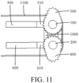
- both the first elastic connector 700 and the second elastic connector 1000 can adapt to a change in the distance between the first rotating shaft 100 and the second rotating shaft 200 through deformation, and the first elastic connector 700 and the second elastic connector 1000 are spaced apart, thereby improving the balance of support.
- the first elastic connector 700 and the second elastic connector 1000 are arranged at both ends of the first rotating shaft 100 and the second rotating shaft 200 respectively.
- both ends of the folding electronic device are arranged with elastic connectors in a folding direction, folding degrees of the both ends of the folding electronic device are the same during folding of the folding electronic device, thereby avoiding the damage of the folding electronic device caused by different folding degrees of the both ends during folding of the folding electronic device.
- the second connecting portion 600 may be fixedly connected to the second rotating shaft 200, and the second connecting portion 600 may be provided with a second notch 630.
- the second rotating shaft 200 may be fixed to an edge of a length of the second connecting portion 600, a diameter of the second rotating shaft 200 may be less than a thickness of the second connecting portion 600, the second notch 630 may be provided at the edge of the length of the second connecting portion 600, both ends of the second rotating shaft 200 are connected at two opposite edges of the second notch 630, and the two edges of the second notch 630 may be drilled to fix the second rotating shaft 200 in holes of the two edges of the second notch 630.
- the second rotating shaft 200 and the second notch 630 form a second accommodating space, and a part of the second gear 400 is located in the second accommodating space.
- Such a structure enables the second connecting portion 600 to sacrifice a partial structure of the second connecting portion 600 to form a space for accommodating at least a part of the second gear 400, so that the folding mechanism is more compact in structure and occupies less space.
- the first accommodating space and the second accommodating space have a relative space, and at least part of the first gear 300 and the second gear 400 may be placed in the space, thereby reducing occupation of another space inside the folding electronic device, and being beneficial to reducing a size of the whole device and reducing material loss on the premise that all functions of the folding electronic device can be implemented.
- the first gear 300 may be a first convex gear
- the second gear 400 may be a second convex gear
- the first convex gear and the second convex gear are not circular gears.
- the first elastic connector 700 is stretched or compressed at the same time, the axis center distance between the first rotating shaft 100 and the second rotating shaft 200 also increases or decreases, and the bending radius of the folding electronic device also increases or decreases.
- the first gear 300 may be a first eccentric gear
- the second gear 400 may be a second eccentric gear.
- the eccentric gear is still a circular gear, but a rotation center of the eccentric gear is not a geometric center of the circular gear. Because the eccentric gear is still a circular gear, the eccentric gear has an advantage of simple manufacture.
- an embodiment of this application discloses a folding electronic device, which may include a flexible screen 1100, a first housing, a second housing, and the folding mechanism described above.
- the axis center distance between the first rotating shaft 100 and the second rotating shaft 200 increases, and bending radiuses at the first connecting sheet and the second connecting sheet increase, so that the flexible screen 1100 of the folding electronic device is located between the first housing and the second housing, which can avoid direct contact between the flexible screen 1100 and an external environment, and avoid damage or friction of the flexible screen 1100, thereby prolonging the service life of the flexible screen 1100.
Landscapes
- Engineering & Computer Science (AREA)
- General Engineering & Computer Science (AREA)
- Signal Processing (AREA)
- Physics & Mathematics (AREA)
- General Physics & Mathematics (AREA)
- Theoretical Computer Science (AREA)
- Mechanical Engineering (AREA)
- Microelectronics & Electronic Packaging (AREA)
- Telephone Set Structure (AREA)
- Casings For Electric Apparatus (AREA)
- Pivots And Pivotal Connections (AREA)
Claims (10)
- Faltmechanismus, der auf eine faltbare elektronische Vorrichtung angewendet wird, umfassend eine erste rotierende Welle (100), eine zweite rotierende Welle (200), ein erstes Zahnrad (300), ein zweites Zahnrad (400), einen ersten Verbindungsabschnitt (500), einen zweiten Verbindungsabschnitt (600) und ein erstes elastisches Verbindungselement (700), wobei
der erste Verbindungsabschnitt (500) mit der ersten rotierenden Welle (100) verbunden ist, der zweite Verbindungsabschnitt (600) mit der zweiten rotierenden Welle (200) verbunden ist, sowohl die erste rotierende Welle (100) als auch die zweite rotierende Welle (200) drehbar mit dem ersten elastischen Verbindungselement (700) verbunden sind, das erste Zahnrad (300) auf der ersten rotierenden Welle (100) montiert ist, das zweite Zahnrad (400) auf der zweiten rotierenden Welle (200) montiert ist, das erste Zahnrad (300) mit dem zweiten Zahnrad (400) in Eingriff steht, das erste Zahnrad (300) eine erste distale Kante und eine erste proximale Kante aufweist, das zweite Zahnrad (400) eine zweite distale Kante und eine zweite proximale Kante aufweist, das erste elastische Verbindungselement (700) so konfiguriert ist, dass es bei einer ineinandergreifenden Drehung des ersten Zahnrads (300) und des zweiten Zahnrads (400) verlängert oder verkürzt wird, der Faltmechanismus einen ersten Zustand, in dem die erste distale Kante mit der zweiten distalen Kante ineinandergreift, und einen zweiten Zustand aufweist, in dem die erste proximale Kante mit der zweiten proximalen Kante ineinandergreift. - Faltmechanismus nach Anspruch 1, wobei die erste rotierende Welle (100) verschiebbar mit einer ersten Okklusionsstruktur (110) ummantelt ist, eine dem ersten Zahnrad (300) zugewandte Fläche der ersten Okklusionsstruktur (110) mit ersten okklusalen Zähnen (111) versehen ist, eine Endfläche des ersten Zahnrads (300), die der ersten Okklusionsstruktur (110) zugewandt ist, mit zweiten okklusalen Zähnen (310) versehen ist, der erste Verbindungsabschnitt (500) eine erste Begrenzungsfläche (510) aufweist, die dem ersten Zahnrad (300) zugewandt ist, ein erster elastischer Mechanismus in einem vorgespannten Zustand zwischen der ersten Okklusionsstruktur (110) und der ersten Begrenzungsfläche (510) angeordnet ist, die ersten okklusalen Zähne (111) elastisch mit den zweiten okklusalen Zähnen (310) ineinandergreifen und das erste Zahnrad (300) mit dem ersten elastischen Verbindungselement (700) in Kontakt steht; und/oder
die zweite rotierende Welle (200) verschiebbar mit einer zweiten Okklusionsstruktur (210) ummantelt ist, eine Endfläche des zweiten Zahnrads (400), die den zweiten okklusalen Zähnen (310) zugewandt ist, mit dritten okklusalen Zähnen (410) versehen ist, eine Endfläche der zweiten Okklusionsstruktur (210), die dem zweiten Zahnrad (400) zugewandt ist, mit vierten okklusalen Zähnen (311) versehen ist, der zweite Verbindungsabschnitt (600) eine zweite Begrenzungsfläche (610) aufweist, die dem zweiten Zahnrad (400) zugewandt ist, ein zweiter elastischer Mechanismus in einem vorgespannten Zustand zwischen der zweiten Okklusionsstruktur (210) und der zweiten Begrenzungsfläche (610) angeordnet ist, die dritten okklusalen Zähne (410) elastisch mit den vierten okklusalen Zähnen (311) ineinandergreifen und das zweite Zahnrad (400) mit dem ersten elastischen Verbindungselement (700) in Kontakt steht. - Faltmechanismus nach Anspruch 2, wobei entweder die erste Okklusionsstruktur (110) oder die zweite Okklusionsstruktur (210) mit einer Hülse versehen ist, die andere mit einer Gleitstange (220) versehen ist und die Gleitstange (220) gleitend in der Hülse sitzt.
- Faltmechanismus nach Anspruch 3, wobei in einem Fall, in dem die erste Okklusionsstruktur (110) mit der Hülse und die zweite Okklusionsstruktur (210) mit der Gleitstange (220) versehen ist, der erste elastische Mechanismus zwischen der Hülse und der ersten Begrenzungsfläche (510) angeordnet ist und der zweite elastische Mechanismus zwischen der Gleitstange (220) und der zweiten Begrenzungsfläche (610) angeordnet ist; und
in einem Fall, in dem die erste Okklusionsstruktur (110) mit der Gleitstange (220) und die zweite Okklusionsstruktur (210) mit der Hülse versehen ist, der erste elastische Mechanismus zwischen der Gleitstange (220) und der ersten Begrenzungsfläche (510) angeordnet ist und der zweite elastische Mechanismus zwischen der Hülse und der zweiten Begrenzungsfläche (610) angeordnet ist. - Faltmechanismus nach Anspruch 2, wobei der erste elastische Mechanismus auf der ersten rotierenden Welle (100) oder der zweite elastische Mechanismus auf der zweiten rotierenden Welle (200) gelagert ist.
- Faltmechanismus nach Anspruch 2, wobei der Faltmechanismus ferner ein zweites elastisches Verbindungselement (1000) umfasst, sowohl die erste rotierende Welle (100) als auch die zweite rotierende Welle (200) gleitend mit dem zweiten elastischen Verbindungselement (1000) verbunden sind, das erste Zahnrad (300) und der erste elastische Mechanismus zwischen dem ersten elastischen Verbindungselement (700) und dem zweiten elastischen Verbindungselement (1000) angeordnet sind und das zweite Zahnrad (400) und der zweite elastische Mechanismus zwischen dem ersten elastischen Verbindungselement (700) und dem zweiten elastischen Verbindungselement (1000) angeordnet sind.
- Faltmechanismus nach Anspruch 1, wobei der erste Verbindungsabschnitt (500) fest mit der ersten rotierenden Welle (100) verbunden ist, der erste Verbindungsabschnitt (500) mit einer ersten Kerbe (530) versehen ist, beide Enden der ersten rotierenden Welle (100) mit zwei gegenüberliegenden Kanten der ersten Kerbe (530) verbunden sind, die erste rotierende Welle (100) und die erste Kerbe (530) einen ersten Aufnahmeraum bilden und ein Teil des ersten Zahnrads (300) in dem ersten Aufnahmeraum angeordnet ist; und/oder
der zweite Verbindungsabschnitt (600) fest mit der zweiten rotierenden Welle (200) verbunden ist, der zweite Verbindungsabschnitt (600) mit einer zweiten Kerbe (630) versehen ist, beide Enden der zweiten rotierenden Welle (200) mit zwei gegenüberliegenden Kanten der zweiten Kerbe (630) verbunden sind, die zweite rotierende Welle (200) und die zweite Kerbe (630) einen zweiten Aufnahmeraum bilden und ein Teil des zweiten Zahnrads (400) in dem zweiten Aufnahmeraum angeordnet ist. - Faltmechanismus nach Anspruch 1, wobei das erste Zahnrad (300) ein erstes konvexes Zahnrad ist und das zweite Zahnrad (400) ein zweites konvexes Zahnrad ist; oder das erste Zahnrad (300) ein erstes exzentrisches Zahnrad ist und das zweite Zahnrad (400) ein zweites exzentrisches Zahnrad ist.
- Faltbare elektronische Vorrichtung, umfassend einen flexiblen Bildschirm (1100), ein erstes Gehäuse, ein zweites Gehäuse und den Faltmechanismus nach einem der Ansprüche 1 bis 8, wobeidas erste Gehäuse mit dem ersten Verbindungsabschnitt (500) verbunden ist und mit dem ersten Verbindungsabschnitt (500) drehbar ist, und das zweite Gehäuse mit dem zweiten Verbindungsabschnitt (600) verbunden ist und mit dem zweiten Verbindungsabschnitt (600) drehbar ist;der flexible Bildschirm (1100) einen ersten Bereich, einen zweiten Bereich und einen Verbindungsbereich umfasst, wobei der erste Bereich mit dem zweiten Bereich über den Verbindungsbereich verbunden ist, der erste Bereich mit dem ersten Gehäuse verbunden ist und der zweite Bereich mit dem zweiten Gehäuse verbunden ist;in einem Fall, in dem sich das erste Gehäuse relativ zum zweiten Gehäuse in einen zusammengeklappten Zustand der elektronischen Vorrichtung dreht und der flexible Bildschirm (1100) zwischen dem ersten Gehäuse und dem zweiten Gehäuse angeordnet ist, die erste distale Kante mit der zweiten distalen Kante ineinandergreift; und in einem Fall, in dem sich das erste Gehäuse relativ zum zweiten Gehäuse in den zusammengeklappten Zustand der elektronischen Vorrichtung dreht und der erste Bereich und der zweite Bereich auf zwei gegenüberliegenden Seiten des ersten Gehäuses und des zweiten Gehäuses angeordnet sind, die erste proximale Kante mit der zweiten proximalen Kante ineinandergreift.
- Elektronische Vorrichtung nach Anspruch 9, wobei der erste Verbindungsabschnitt (500) ein erstes Verbindungsblech ist, das fest mit dem ersten Gehäuse verbunden ist, und der zweite Verbindungsabschnitt (600) ein zweites Verbindungsblech ist, das fest mit dem zweiten Gehäuse verbunden ist.
Applications Claiming Priority (2)
| Application Number | Priority Date | Filing Date | Title |
|---|---|---|---|
| CN202011616737.8A CN112738308B (zh) | 2020-12-30 | 2020-12-30 | 折叠机构及折叠式电子设备 |
| PCT/CN2021/142603 WO2022143795A1 (zh) | 2020-12-30 | 2021-12-29 | 折叠机构及折叠式电子设备 |
Publications (3)
| Publication Number | Publication Date |
|---|---|
| EP4274200A1 EP4274200A1 (de) | 2023-11-08 |
| EP4274200A4 EP4274200A4 (de) | 2024-06-26 |
| EP4274200B1 true EP4274200B1 (de) | 2025-04-16 |
Family
ID=75610426
Family Applications (1)
| Application Number | Title | Priority Date | Filing Date |
|---|---|---|---|
| EP21914527.3A Active EP4274200B1 (de) | 2020-12-30 | 2021-12-29 | Klappmechanismus und klappbare elektronische vorrichtung |
Country Status (7)
| Country | Link |
|---|---|
| US (1) | US12398750B2 (de) |
| EP (1) | EP4274200B1 (de) |
| JP (1) | JP2024505347A (de) |
| KR (1) | KR102829947B1 (de) |
| CN (1) | CN112738308B (de) |
| ES (1) | ES3028032T3 (de) |
| WO (1) | WO2022143795A1 (de) |
Families Citing this family (9)
| Publication number | Priority date | Publication date | Assignee | Title |
|---|---|---|---|---|
| CN112738308B (zh) * | 2020-12-30 | 2023-05-09 | 维沃移动通信有限公司 | 折叠机构及折叠式电子设备 |
| CN115695595B (zh) * | 2021-07-21 | 2025-09-12 | 华为技术有限公司 | 折叠机构及电子设备 |
| CN113572875A (zh) * | 2021-07-24 | 2021-10-29 | 上海富驰高科技股份有限公司 | 一种折叠屏安装结构 |
| CN115750576B (zh) * | 2021-09-03 | 2025-07-08 | 北京小米移动软件有限公司 | 移动终端 |
| CN115862471B (zh) * | 2022-11-24 | 2025-05-06 | 合肥维信诺科技有限公司 | 可折叠支撑装置和可折叠显示装置 |
| CN115985198B (zh) * | 2023-01-31 | 2025-04-08 | 武汉天马微电子有限公司 | 折叠机构及显示装置 |
| CN116447217A (zh) * | 2023-04-23 | 2023-07-18 | 维沃移动通信有限公司 | 铰链组件和电子设备 |
| CN116668570B (zh) * | 2023-06-20 | 2026-01-13 | 维沃移动通信有限公司 | 铰链组件及电子设备 |
| CN118405069A (zh) * | 2024-04-29 | 2024-07-30 | 惠科股份有限公司 | 转轴机构、显示装置及车辆 |
Family Cites Families (51)
| Publication number | Priority date | Publication date | Assignee | Title |
|---|---|---|---|---|
| JP4888289B2 (ja) * | 2007-09-06 | 2012-02-29 | 富士通株式会社 | 連結装置および電子機器 |
| CN201420801Y (zh) * | 2009-05-08 | 2010-03-10 | 连鋐科技股份有限公司 | 垂直承架具凹轮及止挡块功能的自动闭合枢纽器 |
| KR101804576B1 (ko) * | 2011-04-26 | 2017-12-04 | 삼성전자주식회사 | 휴대 단말기의 힌지 장치 |
| US8578561B2 (en) * | 2012-01-19 | 2013-11-12 | Shin Zu Shing Co., Ltd. | Dual-axis hinge and portable device with the same |
| US9798359B2 (en) * | 2014-02-21 | 2017-10-24 | Samsung Electronics Co., Ltd. | Foldable device |
| US20170192467A1 (en) | 2016-01-02 | 2017-07-06 | Lenovo (Singapore) Pte. Ltd. | Hinge assemblies |
| KR102520552B1 (ko) * | 2016-06-24 | 2023-04-12 | 삼성전자주식회사 | 복수의 디스플레이를 포함하는 전자 장치 |
| US9848502B1 (en) * | 2017-03-24 | 2017-12-19 | Shin Zu Shing Co., Ltd. | Hinge assembly and foldable display device using the same |
| CN206918043U (zh) * | 2017-04-19 | 2018-01-23 | 广东欧珀移动通信有限公司 | 转轴组件及可折叠终端 |
| CN207782858U (zh) * | 2017-06-06 | 2018-08-28 | 杭州安费诺飞凤通信部品有限公司 | 柔性屏移动终端铰链及柔性屏移动终端 |
| TWI699155B (zh) * | 2018-03-02 | 2020-07-11 | 仁寶電腦工業股份有限公司 | 鉸鏈結構與具有其的電子裝置 |
| CN110324441B (zh) * | 2018-03-30 | 2021-03-09 | Oppo广东移动通信有限公司 | 移动终端 |
| WO2020010987A1 (zh) | 2018-07-13 | 2020-01-16 | Oppo广东移动通信有限公司 | 可折叠电子设备 |
| CN108664087A (zh) * | 2018-07-23 | 2018-10-16 | Oppo广东移动通信有限公司 | 便携式电子装置及其柔性显示装置 |
| CN208538027U (zh) * | 2018-07-23 | 2019-02-22 | Oppo广东移动通信有限公司 | 便携式电子装置及其柔性显示装置 |
| KR102444383B1 (ko) * | 2018-08-07 | 2022-09-16 | 후아웨이 테크놀러지 컴퍼니 리미티드 | 회전 샤프트 연결 구조체 및 절첩식 장치 |
| CN108874048B (zh) * | 2018-08-10 | 2024-09-20 | 昆山玮硕恒基智能科技股份有限公司 | 折叠屏转轴及折叠屏电子设备 |
| TWI716042B (zh) * | 2018-09-06 | 2021-01-11 | 仁寶電腦工業股份有限公司 | 樞軸模組及電子裝置 |
| CN209641241U (zh) * | 2018-11-08 | 2019-11-15 | 上海富驰高科技股份有限公司 | 一种柔性屏幕的折叠机构 |
| CN109654112B (zh) | 2018-12-29 | 2020-06-23 | 兆利科技工业股份有限公司 | 折叠式装置的转轴模组 |
| TWM582540U (zh) | 2019-04-12 | 2019-08-21 | 宏碁股份有限公司 | 轉軸模組與電子裝置 |
| CN111816067B (zh) * | 2019-04-12 | 2023-12-29 | 三星电子株式会社 | 可折叠电子装置 |
| CN110145535B (zh) | 2019-06-14 | 2024-03-15 | 深圳市长盈精密技术股份有限公司 | 均衡控制机构、折叠显示装置及通讯设备 |
| CN112145542B (zh) * | 2019-06-27 | 2022-01-11 | 华为技术有限公司 | 折叠模组及折叠式电子设备 |
| CN209881842U (zh) * | 2019-07-18 | 2019-12-31 | 广东金力变速科技股份有限公司 | 一种用于可折叠屏产品的屏幕可折叠构造 |
| CN210351882U (zh) * | 2019-07-18 | 2020-04-17 | 广东金力变速科技股份有限公司 | 一种可折叠屏产品的凸轮顶升机构 |
| CN210637370U (zh) * | 2019-07-31 | 2020-05-29 | 安费诺飞凤(安吉)通信部品有限公司 | 一种铰链 |
| TWI709843B (zh) * | 2019-09-19 | 2020-11-11 | 富世達股份有限公司 | 軟性顯示屏幕之折收轉軸結構 |
| US11099611B2 (en) * | 2019-09-26 | 2021-08-24 | Dell Products L.P. | Synchronized expandable dual axle hinge and clutch |
| CN210640916U (zh) * | 2019-10-30 | 2020-05-29 | 杭州安费诺飞凤通信部品有限公司 | 一种应用于柔性屏终端的运动机构 |
| CN113883156A (zh) * | 2020-07-01 | 2022-01-04 | 华为技术有限公司 | 折叠模组及折叠式电子设备 |
| CN111049954B (zh) | 2019-12-18 | 2021-04-06 | Oppo广东移动通信有限公司 | 折叠装置及电子设备 |
| TWM611763U (zh) * | 2020-02-20 | 2021-05-11 | 信錦企業股份有限公司 | 折疊式電子裝置 |
| CN212034155U (zh) * | 2020-04-01 | 2020-11-27 | Oppo广东移动通信有限公司 | 折叠机构、壳体、电子装置 |
| EP4128728B1 (de) * | 2020-05-27 | 2025-02-26 | Samsung Electronics Co., Ltd. | Elektronische vorrichtung mit scharnier- und armstruktur |
| KR20220004843A (ko) * | 2020-07-02 | 2022-01-12 | 삼성디스플레이 주식회사 | 표시 장치 |
| CN111981275B (zh) * | 2020-08-28 | 2022-04-15 | 京东方科技集团股份有限公司 | 柔性屏弯折治具及柔性屏弯折方法 |
| KR20230056736A (ko) * | 2020-12-07 | 2023-04-27 | 엘지전자 주식회사 | 이동 단말기 |
| CN115176214B (zh) * | 2020-12-25 | 2025-08-26 | 京东方科技集团股份有限公司 | 弯折装置及显示装置 |
| EP4175265B1 (de) * | 2020-12-28 | 2025-08-06 | Samsung Electronics Co., Ltd. | Scharnierstruktur und klappbare elektronische vorrichtung damit |
| CN112738308B (zh) * | 2020-12-30 | 2023-05-09 | 维沃移动通信有限公司 | 折叠机构及折叠式电子设备 |
| EP4216520B1 (de) * | 2021-01-05 | 2026-01-28 | Samsung Electronics Co., Ltd. | Elektronische vorrichtung mit scharnierstruktur |
| TWI747708B (zh) | 2021-01-12 | 2021-11-21 | 富世達股份有限公司 | 雙軸同步式鉸鏈 |
| EP4207144B1 (de) * | 2021-01-13 | 2025-03-12 | Samsung Electronics Co., Ltd. | Faltbare flexible anzeigevorrichtung und elektronische vorrichtung |
| CN114857163B (zh) * | 2021-02-05 | 2024-03-26 | 深圳富泰宏精密工业有限公司 | 旋转连接结构及电子设备 |
| TWI748917B (zh) * | 2021-04-21 | 2021-12-01 | 富世達股份有限公司 | 雙軸同步式鉸鏈 |
| TWI763516B (zh) * | 2021-06-02 | 2022-05-01 | 富世達股份有限公司 | 雙軸多段切換式鉸鏈 |
| US11834880B2 (en) * | 2021-06-25 | 2023-12-05 | Sinher Technology Inc. | Thinned hinge |
| EP4318181B1 (de) * | 2021-07-20 | 2025-09-17 | Samsung Electronics Co., Ltd. | Elektronische vorrichtung mit scharniermodul |
| CN114078390B (zh) * | 2021-11-15 | 2023-02-28 | 武汉华星光电半导体显示技术有限公司 | 折叠显示装置 |
| CN117722429A (zh) * | 2022-09-09 | 2024-03-19 | 深圳富泰宏精密工业有限公司 | 铰链结构以及终端装置 |
-
2020
- 2020-12-30 CN CN202011616737.8A patent/CN112738308B/zh active Active
-
2021
- 2021-12-29 JP JP2023538997A patent/JP2024505347A/ja active Pending
- 2021-12-29 ES ES21914527T patent/ES3028032T3/es active Active
- 2021-12-29 WO PCT/CN2021/142603 patent/WO2022143795A1/zh not_active Ceased
- 2021-12-29 KR KR1020237024925A patent/KR102829947B1/ko active Active
- 2021-12-29 EP EP21914527.3A patent/EP4274200B1/de active Active
-
2023
- 2023-05-31 US US18/326,324 patent/US12398750B2/en active Active
Also Published As
| Publication number | Publication date |
|---|---|
| EP4274200A4 (de) | 2024-06-26 |
| KR102829947B1 (ko) | 2025-07-04 |
| KR20230119011A (ko) | 2023-08-14 |
| EP4274200A1 (de) | 2023-11-08 |
| US12398750B2 (en) | 2025-08-26 |
| CN112738308A (zh) | 2021-04-30 |
| CN112738308B (zh) | 2023-05-09 |
| US20230304530A1 (en) | 2023-09-28 |
| JP2024505347A (ja) | 2024-02-06 |
| WO2022143795A1 (zh) | 2022-07-07 |
| ES3028032T3 (en) | 2025-06-17 |
Similar Documents
| Publication | Publication Date | Title |
|---|---|---|
| EP4274200B1 (de) | Klappmechanismus und klappbare elektronische vorrichtung | |
| CN113202857B (zh) | 铰链、柔性显示面板及电子装置 | |
| CN114688147B (zh) | 一种转动机构、支撑装置以及折叠屏终端 | |
| EP4443855A1 (de) | Elektronische vorrichtung | |
| CN112468623A (zh) | 电子设备 | |
| CN116517950B (zh) | 一种转轴机构、支撑装置和折叠屏设备 | |
| CN105867533B (zh) | 一种电子设备 | |
| CN112492780A (zh) | 电子设备 | |
| WO2023197993A1 (zh) | 铰链机构和电子设备 | |
| CN113534893B (zh) | 折叠式电子装置 | |
| US12353256B2 (en) | Display device and folding display module thereof | |
| CN114244934B (zh) | 电子设备 | |
| CN114244936B (zh) | 电子设备 | |
| EP4495443B1 (de) | Scharniermechanismus und elektronische vorrichtung | |
| CN113948008B (zh) | 折叠显示装置 | |
| CN113329109A (zh) | 电子设备 | |
| CN219372459U (zh) | 一种折叠装置及电子设备 | |
| CN116044891A (zh) | 转轴机构、支撑装置和可折叠电子设备 | |
| EP4254129B1 (de) | Radialwellengerät und faltbare elektronische vorrichtung | |
| WO2023284683A1 (zh) | 电子设备 | |
| CN117207226B (zh) | 一种仿生手及机器人 | |
| WO2023109781A1 (zh) | 电子设备 | |
| WO2020135147A1 (zh) | 移动终端 | |
| CN111219408B (zh) | 屏幕模组和电子设备 | |
| CN212838939U (zh) | 铰链机构及电子设备 |
Legal Events
| Date | Code | Title | Description |
|---|---|---|---|
| STAA | Information on the status of an ep patent application or granted ep patent |
Free format text: STATUS: THE INTERNATIONAL PUBLICATION HAS BEEN MADE |
|
| PUAI | Public reference made under article 153(3) epc to a published international application that has entered the european phase |
Free format text: ORIGINAL CODE: 0009012 |
|
| STAA | Information on the status of an ep patent application or granted ep patent |
Free format text: STATUS: REQUEST FOR EXAMINATION WAS MADE |
|
| 17P | Request for examination filed |
Effective date: 20230531 |
|
| AK | Designated contracting states |
Kind code of ref document: A1 Designated state(s): AL AT BE BG CH CY CZ DE DK EE ES FI FR GB GR HR HU IE IS IT LI LT LU LV MC MK MT NL NO PL PT RO RS SE SI SK SM TR |
|
| DAV | Request for validation of the european patent (deleted) | ||
| DAX | Request for extension of the european patent (deleted) | ||
| A4 | Supplementary search report drawn up and despatched |
Effective date: 20240528 |
|
| RIC1 | Information provided on ipc code assigned before grant |
Ipc: G09F 9/30 20060101ALI20240522BHEP Ipc: H05K 5/00 20060101ALI20240522BHEP Ipc: F16C 11/04 20060101ALI20240522BHEP Ipc: H04M 1/02 20060101AFI20240522BHEP |
|
| GRAP | Despatch of communication of intention to grant a patent |
Free format text: ORIGINAL CODE: EPIDOSNIGR1 |
|
| STAA | Information on the status of an ep patent application or granted ep patent |
Free format text: STATUS: GRANT OF PATENT IS INTENDED |
|
| INTG | Intention to grant announced |
Effective date: 20250121 |
|
| GRAS | Grant fee paid |
Free format text: ORIGINAL CODE: EPIDOSNIGR3 |
|
| GRAA | (expected) grant |
Free format text: ORIGINAL CODE: 0009210 |
|
| STAA | Information on the status of an ep patent application or granted ep patent |
Free format text: STATUS: THE PATENT HAS BEEN GRANTED |
|
| AK | Designated contracting states |
Kind code of ref document: B1 Designated state(s): AL AT BE BG CH CY CZ DE DK EE ES FI FR GB GR HR HU IE IS IT LI LT LU LV MC MK MT NL NO PL PT RO RS SE SI SK SM TR |
|
| REG | Reference to a national code |
Ref country code: GB Ref legal event code: FG4D |
|
| REG | Reference to a national code |
Ref country code: CH Ref legal event code: EP Ref country code: DE Ref legal event code: R096 Ref document number: 602021029408 Country of ref document: DE |
|
| REG | Reference to a national code |
Ref country code: IE Ref legal event code: FG4D |
|
| REG | Reference to a national code |
Ref country code: NL Ref legal event code: FP |
|
| REG | Reference to a national code |
Ref country code: ES Ref legal event code: FG2A Ref document number: 3028032 Country of ref document: ES Kind code of ref document: T3 Effective date: 20250617 |
|
| REG | Reference to a national code |
Ref country code: AT Ref legal event code: MK05 Ref document number: 1786629 Country of ref document: AT Kind code of ref document: T Effective date: 20250416 |
|
| PG25 | Lapsed in a contracting state [announced via postgrant information from national office to epo] |
Ref country code: FI Free format text: LAPSE BECAUSE OF FAILURE TO SUBMIT A TRANSLATION OF THE DESCRIPTION OR TO PAY THE FEE WITHIN THE PRESCRIBED TIME-LIMIT Effective date: 20250416 Ref country code: PT Free format text: LAPSE BECAUSE OF FAILURE TO SUBMIT A TRANSLATION OF THE DESCRIPTION OR TO PAY THE FEE WITHIN THE PRESCRIBED TIME-LIMIT Effective date: 20250818 |
|
| REG | Reference to a national code |
Ref country code: LT Ref legal event code: MG9D |
|
| PG25 | Lapsed in a contracting state [announced via postgrant information from national office to epo] |
Ref country code: GR Free format text: LAPSE BECAUSE OF FAILURE TO SUBMIT A TRANSLATION OF THE DESCRIPTION OR TO PAY THE FEE WITHIN THE PRESCRIBED TIME-LIMIT Effective date: 20250717 Ref country code: NO Free format text: LAPSE BECAUSE OF FAILURE TO SUBMIT A TRANSLATION OF THE DESCRIPTION OR TO PAY THE FEE WITHIN THE PRESCRIBED TIME-LIMIT Effective date: 20250716 |
|
| PG25 | Lapsed in a contracting state [announced via postgrant information from national office to epo] |
Ref country code: PL Free format text: LAPSE BECAUSE OF FAILURE TO SUBMIT A TRANSLATION OF THE DESCRIPTION OR TO PAY THE FEE WITHIN THE PRESCRIBED TIME-LIMIT Effective date: 20250416 |
|
| PG25 | Lapsed in a contracting state [announced via postgrant information from national office to epo] |
Ref country code: BG Free format text: LAPSE BECAUSE OF FAILURE TO SUBMIT A TRANSLATION OF THE DESCRIPTION OR TO PAY THE FEE WITHIN THE PRESCRIBED TIME-LIMIT Effective date: 20250416 |
|
| PG25 | Lapsed in a contracting state [announced via postgrant information from national office to epo] |
Ref country code: HR Free format text: LAPSE BECAUSE OF FAILURE TO SUBMIT A TRANSLATION OF THE DESCRIPTION OR TO PAY THE FEE WITHIN THE PRESCRIBED TIME-LIMIT Effective date: 20250416 |
|
| PG25 | Lapsed in a contracting state [announced via postgrant information from national office to epo] |
Ref country code: AT Free format text: LAPSE BECAUSE OF FAILURE TO SUBMIT A TRANSLATION OF THE DESCRIPTION OR TO PAY THE FEE WITHIN THE PRESCRIBED TIME-LIMIT Effective date: 20250416 |
|
| PG25 | Lapsed in a contracting state [announced via postgrant information from national office to epo] |
Ref country code: RS Free format text: LAPSE BECAUSE OF FAILURE TO SUBMIT A TRANSLATION OF THE DESCRIPTION OR TO PAY THE FEE WITHIN THE PRESCRIBED TIME-LIMIT Effective date: 20250716 |
|
| PG25 | Lapsed in a contracting state [announced via postgrant information from national office to epo] |
Ref country code: IS Free format text: LAPSE BECAUSE OF FAILURE TO SUBMIT A TRANSLATION OF THE DESCRIPTION OR TO PAY THE FEE WITHIN THE PRESCRIBED TIME-LIMIT Effective date: 20250816 |
|
| PG25 | Lapsed in a contracting state [announced via postgrant information from national office to epo] |
Ref country code: LV Free format text: LAPSE BECAUSE OF FAILURE TO SUBMIT A TRANSLATION OF THE DESCRIPTION OR TO PAY THE FEE WITHIN THE PRESCRIBED TIME-LIMIT Effective date: 20250416 |
|
| PGFP | Annual fee paid to national office [announced via postgrant information from national office to epo] |
Ref country code: NL Payment date: 20251112 Year of fee payment: 5 |
|
| PGFP | Annual fee paid to national office [announced via postgrant information from national office to epo] |
Ref country code: DE Payment date: 20251104 Year of fee payment: 5 |
|
| PGFP | Annual fee paid to national office [announced via postgrant information from national office to epo] |
Ref country code: GB Payment date: 20251114 Year of fee payment: 5 |
|
| PG25 | Lapsed in a contracting state [announced via postgrant information from national office to epo] |
Ref country code: DK Free format text: LAPSE BECAUSE OF FAILURE TO SUBMIT A TRANSLATION OF THE DESCRIPTION OR TO PAY THE FEE WITHIN THE PRESCRIBED TIME-LIMIT Effective date: 20250416 Ref country code: SM Free format text: LAPSE BECAUSE OF FAILURE TO SUBMIT A TRANSLATION OF THE DESCRIPTION OR TO PAY THE FEE WITHIN THE PRESCRIBED TIME-LIMIT Effective date: 20250416 |
|
| PGFP | Annual fee paid to national office [announced via postgrant information from national office to epo] |
Ref country code: IT Payment date: 20251121 Year of fee payment: 5 |
|
| PGFP | Annual fee paid to national office [announced via postgrant information from national office to epo] |
Ref country code: FR Payment date: 20251110 Year of fee payment: 5 |
|
| PG25 | Lapsed in a contracting state [announced via postgrant information from national office to epo] |
Ref country code: CZ Free format text: LAPSE BECAUSE OF FAILURE TO SUBMIT A TRANSLATION OF THE DESCRIPTION OR TO PAY THE FEE WITHIN THE PRESCRIBED TIME-LIMIT Effective date: 20250416 |
|
| PG25 | Lapsed in a contracting state [announced via postgrant information from national office to epo] |
Ref country code: EE Free format text: LAPSE BECAUSE OF FAILURE TO SUBMIT A TRANSLATION OF THE DESCRIPTION OR TO PAY THE FEE WITHIN THE PRESCRIBED TIME-LIMIT Effective date: 20250416 |
|
| PG25 | Lapsed in a contracting state [announced via postgrant information from national office to epo] |
Ref country code: SK Free format text: LAPSE BECAUSE OF FAILURE TO SUBMIT A TRANSLATION OF THE DESCRIPTION OR TO PAY THE FEE WITHIN THE PRESCRIBED TIME-LIMIT Effective date: 20250416 |